g.e.m. - ucf department of · pdf filebuilt up before being written to the sd card ......
TRANSCRIPT

G.E.M.GROUP 8
PEDRO BETANCOURT - CPE
ALEXANDER PATINO - CPE
MOHHAMAD PULLIAM - EE
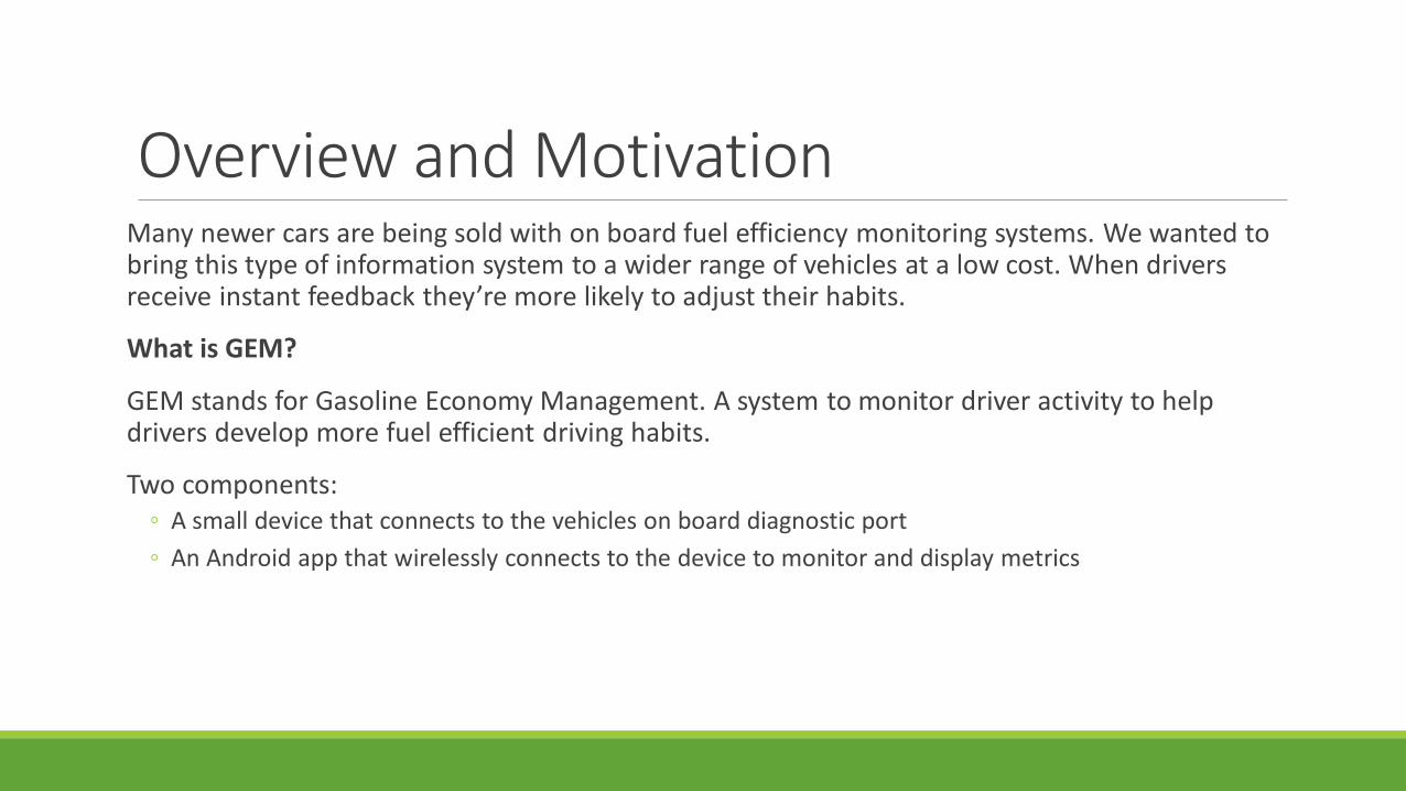
Overview and MotivationMany newer cars are being sold with on board fuel efficiency monitoring systems. We wanted to bring this type of information system to a wider range of vehicles at a low cost. When drivers receive instant feedback they’re more likely to adjust their habits.
What is GEM?
GEM stands for Gasoline Economy Management. A system to monitor driver activity to help drivers develop more fuel efficient driving habits.
Two components:◦ A small device that connects to the vehicles on board diagnostic port
◦ An Android app that wirelessly connects to the device to monitor and display metrics
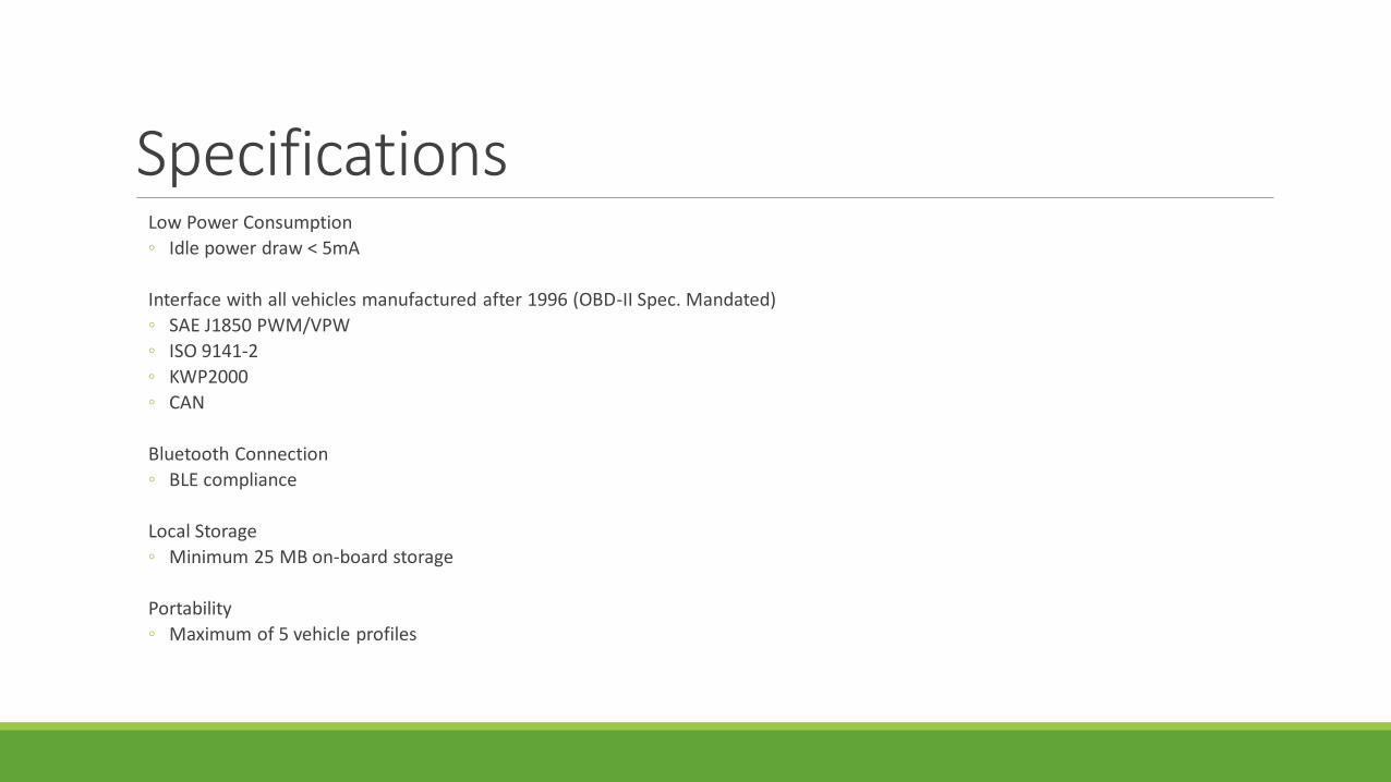
SpecificationsLow Power Consumption
◦ Idle power draw < 5mA
Interface with all vehicles manufactured after 1996 (OBD-II Spec. Mandated)
◦ SAE J1850 PWM/VPW
◦ ISO 9141-2
◦ KWP2000
◦ CAN
Bluetooth Connection
◦ BLE compliance
Local Storage
◦ Minimum 25 MB on-board storage
Portability
◦ Maximum of 5 vehicle profiles
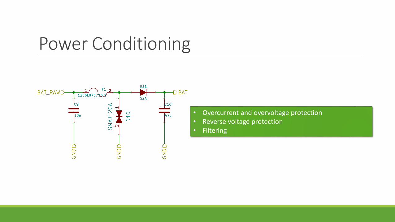
Power Conditioning
• Overcurrent and overvoltage protection• Reverse voltage protection• Filtering

Power Management
Power saving feature. All +5V and BAT subsystems are completely turned off.
+3.3V systems (MCU, Serial Interface, and BT) manage their own power.

Voltage Regulation
• +3.3V and +5V circuit very similar
• 28 uA standby current
• High frequency switcher
• Protection including current limit and thermal shutdown
• Approaches 90% efficiency

Signal Voltages
Name Nominal High Nominal Low
J1850 PWM +5V 0V
J1850 VPW +7V 0V
ISO 9141-2 & KWP2000 +12V 0V
CAN +3.5V +1.5V

KWP2000 Transceiver
• Uses LM339 Quad Comparator
• Open collector output, when non-inverting > inverting the output is floating (High impedance to ground)
• L-line use is not widespread used only for wakeup

KWP2000 ProtocolPin 7: K-line used for signaling
Pin 15: L-Line, optional line used for ECU wakeup
Idle is signal level high
Signals are active pull-down
High signal +12V

J1850 PWM/VPW
• VPW/PWM use the same line but not the same voltage
• Linear regulator uses two different resistor dividers to set voltages, controlled by OBD-II to serial interface

J1850 PWM
Pin 2: BUS+
Pin 10: BUS-
Active bus when BUS+ pulled high and BUS- pulled low
High signal +5V, low signal 0V
1 Bit on bus active for 8uS out of 24uS
0 Bit on bus active for 16uS out of 24uS
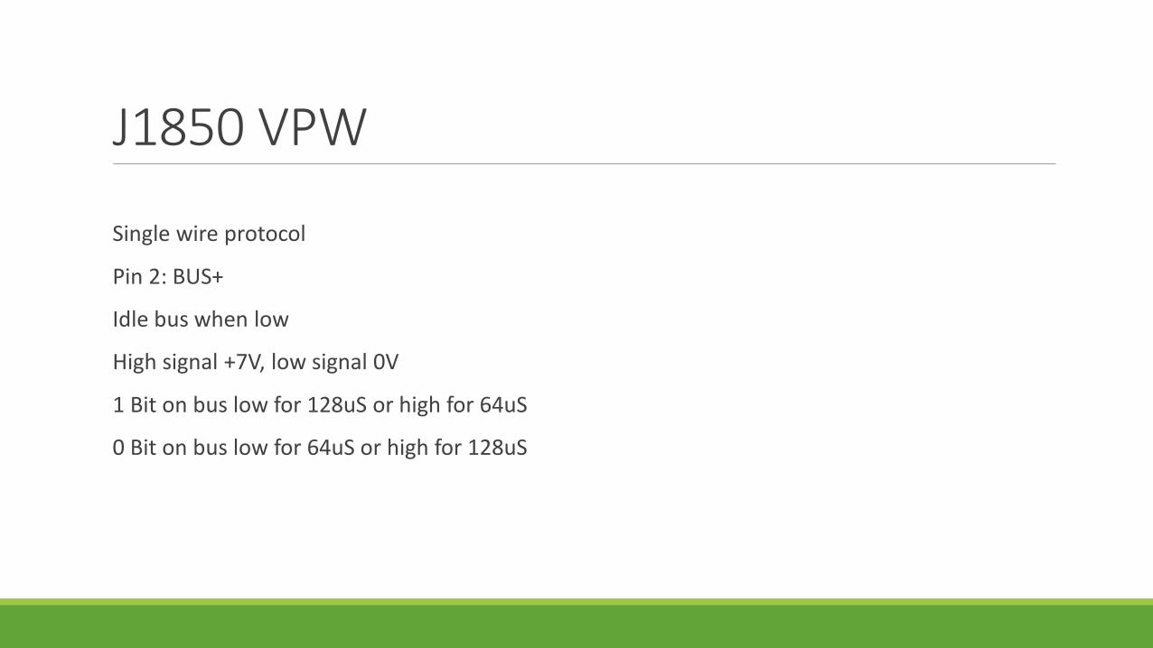
J1850 VPW
Single wire protocol
Pin 2: BUS+
Idle bus when low
High signal +7V, low signal 0V
1 Bit on bus low for 128uS or high for 64uS
0 Bit on bus low for 64uS or high for 128uS

CAN Transceiver
• The MCP2551 is a high speed CAN transceiver
• Supports speeds up to 1 Mbps• CAN is the modern standard for vehicle
data networks• Each node on the CAN network has a
similar controller that handles turning digital input into differential output and vice-versa
• Also provides protection to the CAN bus
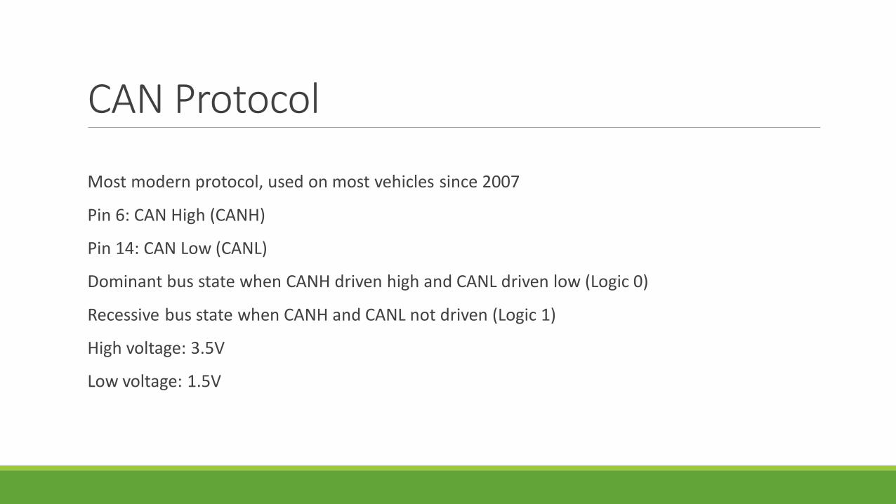
CAN Protocol
Most modern protocol, used on most vehicles since 2007
Pin 6: CAN High (CANH)
Pin 14: CAN Low (CANL)
Dominant bus state when CANH driven high and CANL driven low (Logic 0)
Recessive bus state when CANH and CANL not driven (Logic 1)
High voltage: 3.5V
Low voltage: 1.5V

STN1110 OBD-II to Serial Interface
• Detects protocol and converts to serial data
• Accepts commands via ASCII• Operates using the industry
standard ELM327 protocol to simplify communications
• Has low power sleep mode• Voltage sense can wake
device from low power sleep mode

Front End Board Layout• Current Front End• Does not have MCU,
Bluetooth or SD Card• 2” x 3” (Quarter for
scale)• Board layout is being
optimized
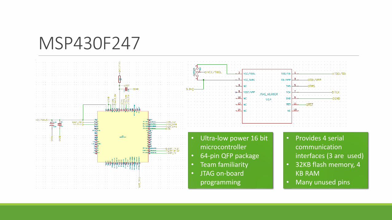
MSP430F247
• Ultra-low power 16 bit microcontroller
• 64-pin QFP package• Team familiarity• JTAG on-board
programming
• Provides 4 serial communication interfaces (3 are used)
• 32KB flash memory, 4 KB RAM
• Many unused pins

RN4020 Bluetooth Module• Bluetooth 4.1 (BLE
ready)• UART communication• ASCII command API• Integrated antenna
and BT stack• MLDP private profile• Avoid bit-banging

On-Board Storage• MicroSD• Low power• High capacity• Portable, removable from board• 8 Pin, SPI communication mode• 3.3 V• File systems have large overhead, raw
data read/writes are required
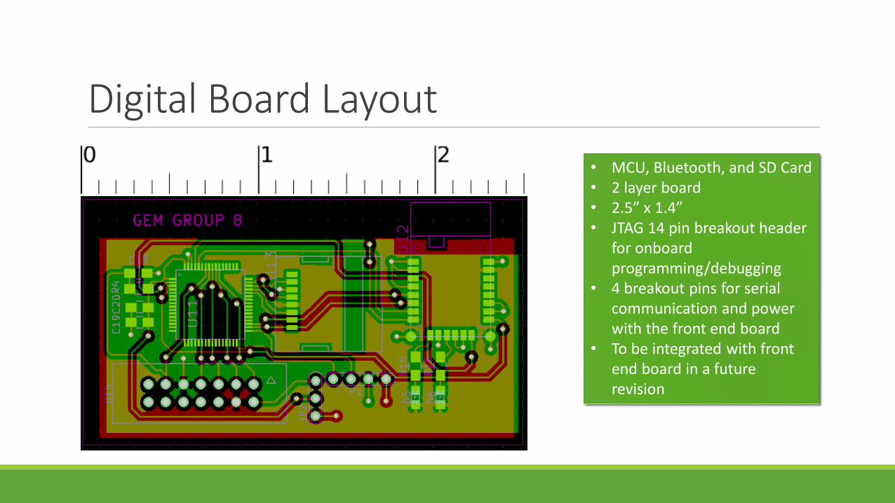
Digital Board Layout
• MCU, Bluetooth, and SD Card• 2 layer board• 2.5” x 1.4” • JTAG 14 pin breakout header
for onboard programming/debugging
• 4 breakout pins for serial communication and power with the front end board
• To be integrated with front end board in a future revision

Firmware Design• Design based on 5 subsystems gelled together by a main
subroutine• Bluetooth • Vehicle profiles• Data logging• OBD-II Data pipelining• Power
• First time power-on state which configures peripherals and enables core functionality
• VIN matching for identifying profiles• Log data when no connection is available• Continuous OBD-II data stream over Bluetooth
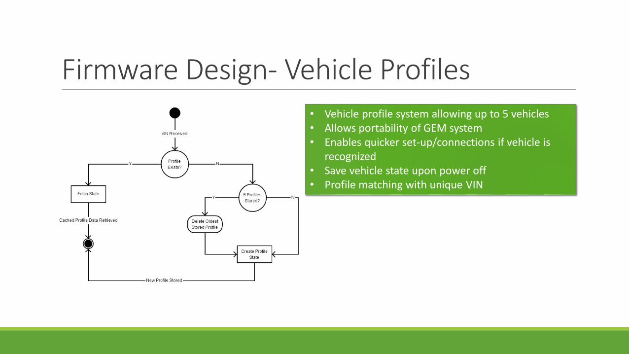
Firmware Design- Vehicle Profiles• Vehicle profile system allowing up to 5 vehicles• Allows portability of GEM system• Enables quicker set-up/connections if vehicle is
recognized• Save vehicle state upon power off• Profile matching with unique VIN

Firmware Design- Bluetooth Connection• Scanning, discovery, and pairing of devices through
the RN4020• Use profile state to establish quicker connections
with previously paired devices• Detect packet loss, and trigger the data logging
subroutine• Enter MLDP state if a stable connection is
established, to prepare device to pipeline OBD-II data
• Full authentication and connection report frame used

Firmware Design- Data Logging
• Data logging routine triggered when no Bluetooth connection can be established
• Data is, instead, transmitted to the onboard SD card
• Works with a read/write state, a frame is built up before being written to the SD card
• Establishing a connection can interrupt this subroutine
• Data is written to the SD card along with a flag indicating there is OBD-II data that has yet to be transmitted to an Android device
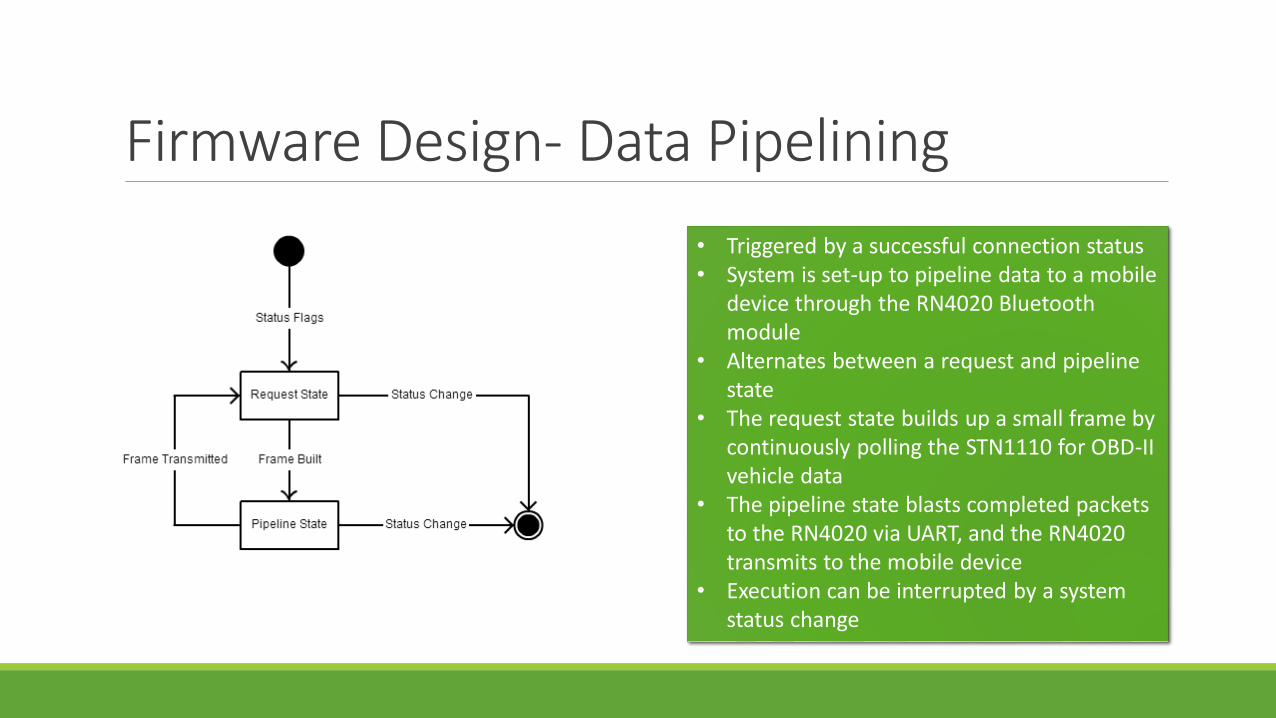
Firmware Design- Data Pipelining
• Triggered by a successful connection status• System is set-up to pipeline data to a mobile
device through the RN4020 Bluetooth module
• Alternates between a request and pipeline state
• The request state builds up a small frame by continuously polling the STN1110 for OBD-II vehicle data
• The pipeline state blasts completed packets to the RN4020 via UART, and the RN4020 transmits to the mobile device
• Execution can be interrupted by a system status change

Firmware Design- Power
• The power subsystem handles all device sleep and idle states
• Can interrupt any other routine’s execution• Wakes up peripheral devices, or interrupts
subroutines and saves the device state before a loss of power occurs

Why Android?One of the earliest application design decisions was which platform(s) to develop the app for.
The following factors were taken into consideration:◦ The team can program in Java
◦ The app could be built using Eclipse or Android Studio on any OS
◦ The lead programmer has an Android device at his disposal
◦ The Android platform is open source
◦ The team wanted to gain experience with Android
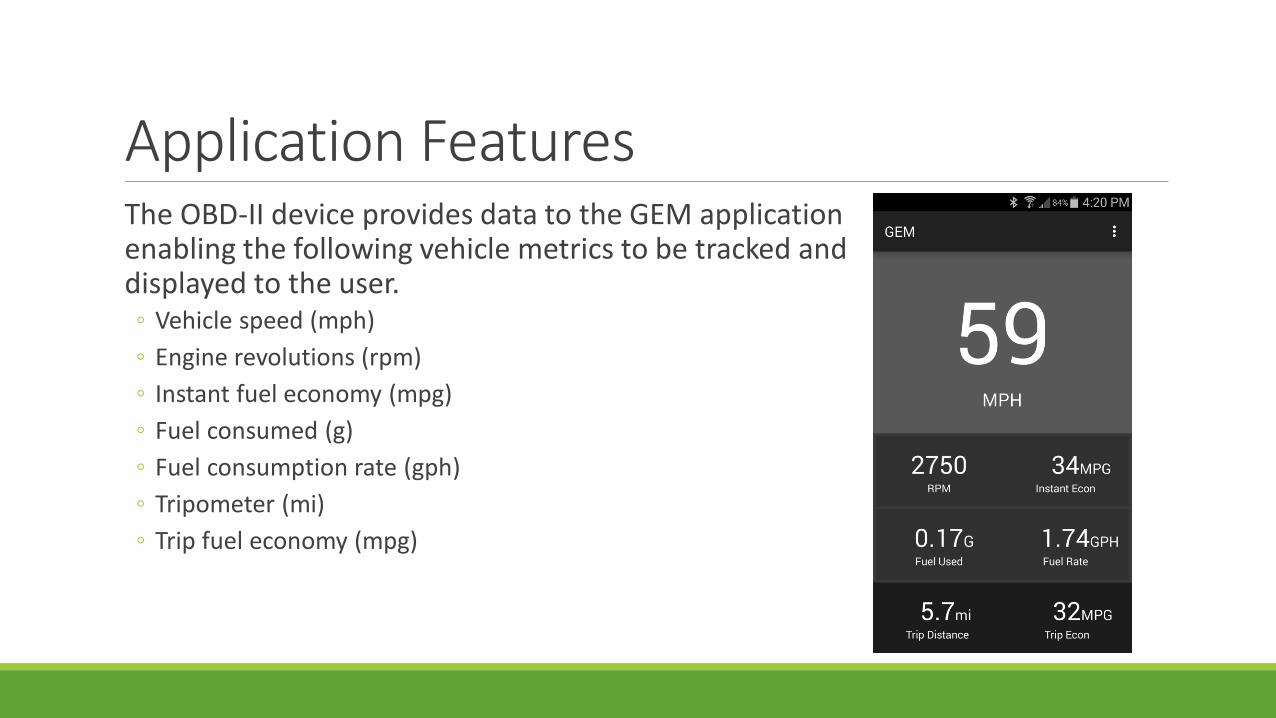
Application FeaturesThe OBD-II device provides data to the GEM application enabling the following vehicle metrics to be tracked and displayed to the user.◦ Vehicle speed (mph)
◦ Engine revolutions (rpm)
◦ Instant fuel economy (mpg)
◦ Fuel consumed (g)
◦ Fuel consumption rate (gph)
◦ Tripometer (mi)
◦ Trip fuel economy (mpg)

Software Development ToolsIn addition to Android Studio the team will use:
◦ SublimeText2 – A cross-platform text and source code editor.
◦ GitHub - An online version control system.
◦ Adobe Photoshop – A raster graphics editor.
◦ OBD-II Emulator GUI – Vehicle data simulator.

Activity Diagram

Class Diagram

Component DescriptionsCLASS MainActivity
◦ Responsible for launching the application, displaying the Home screen and its metrics, handling exceptions, interfacing with the other components, and exiting the application.
CLASS DeviceListActivity
◦ Responsible for scanning for new or paired Bluetooth devices.
CLASS OBD2Service
◦ Responsible for calculating vehicle speed, RPM, MPG, and other relevant information from the received data. Uses three nested classes (AcceptThread, ConnectThread, and ConnectedThread) to handle Bluetooth connection, input/output stream, and vehicle protocols.

Budget to DateItem Quantity Price Supplier
PCB’s 2 x 3 $47.85 Oshpark
Stencils and Jig 2 $26.58 Oshstenil
Circuit Components (R,L,C, IC’s) 2 Sets $103.45 Mouser
OBD-II Emulator 1 $229.00 Freematics
TOTAL $406.88
• Original funding request: $774.08• Remaining budget: $367.20• Remaining items include MSP430 debugging interface and the serial
debugging interface.• We should complete the project very close to the original estimated budget.

Progress
50
0
25
80
80
95
0 10 20 30 40 50 60 70 80 90 100
OVERALL
HARDWARE TESTING
SOFTWARE TESTING
HARDWARE DESIGN
SOFTWARE DESIGN
RESEARCH
Progress %
Progress %
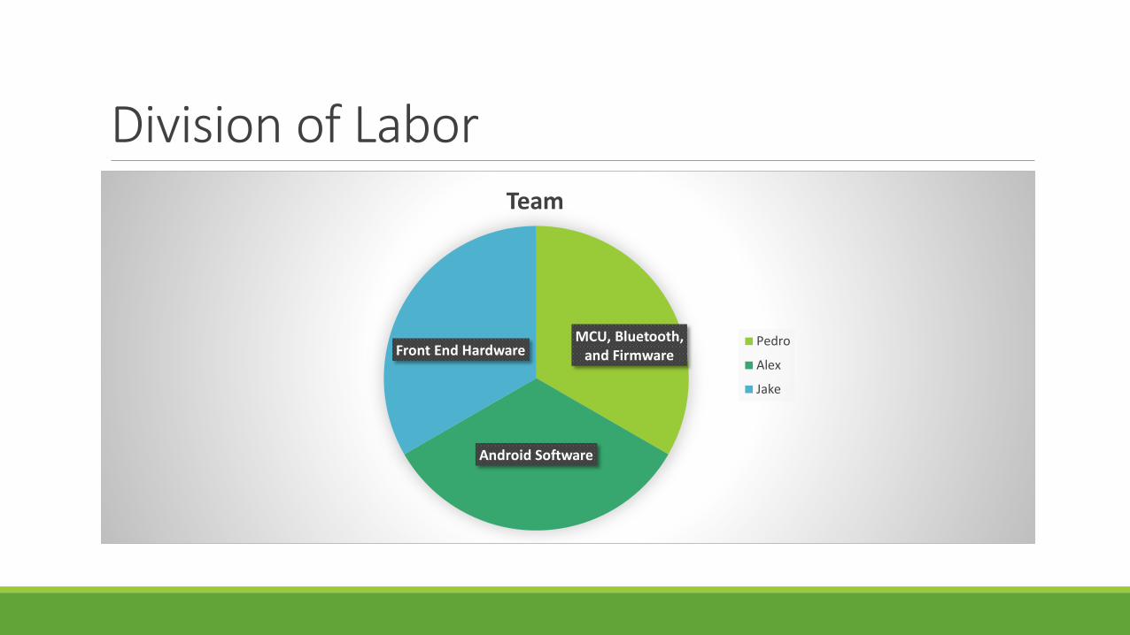
Division of Labor
MCU, Bluetooth, and Firmware
Android Software
Front End Hardware
Team
Pedro
Alex
Jake

Remaining TasksBuild and test front end hardware – 2/8
Build and test wireless/MCU hardware – 2/16
Integration testing for front end and wireless – 2/20
Integration testing for hardware and software – 2/20
If time allows or if serious problems with initial design arise – redesign and rebuild PCB’s
IssuesPCB Layout, right now the ground plane is Swiss cheese. Design can be optimized.
Size. First we want to make sure everything works. The size of the device needs to be small enough that it can be left plugged in.
Power consumption. This is likely to be the most difficult thing to bring within spec. We need to make sure that we can enter sleep mode and then exit sleep mode when required and bring the whole system back up.
Writing raw data to an SD card. Data is written in 512 byte blocks, a file system provides too much overhead.