gebrauchs- und montageanleitung operating and · pdf filegebrauchs- und montageanleitung...
TRANSCRIPT
Gebrauchs- und MontaGeanleitunGoperatinG and installation instructionsGebruiKs- en installatieVoorschriFteninstrucciones de uso y MontajeinstruKcja obsŁuGi i MontaŻuИнструкцИя ПО ЭксПЛуАтАцИИ И МОнтАЖуinstrucţiuni de Montaj şi utilizare
eleKtronisch GereGelter durchlauFerhitzer | electronically controlled instantaneous water heater | eleKtronisch GereGelde eleKtrische doorstroMer | calentador instantáneo con reGulación electrónica | eleKtronicznie reGulowany przepŁywowy oGrzewacz wody | ПрОтОчный вОдОнАгревАтеЛь с ЭЛектрОннОй регуЛИрОвкОй | Încălzitor instant controlat electronic
» del 18 sli 25a electronic lcd» del 18/21/24 sli electronic lcd » del 27 sli electronic lcd» del 18 a» del 27 a
List of contents
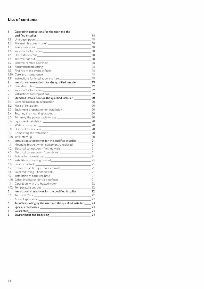
1 Operatinginstructionsfortheuserandthequalifiedinstaller________________________________ 18
1.1 Unitdescription____________________________________ 181.2 Themainfeaturesinbrief ____________________________ 181.3 Safetyinstruction___________________________________ 181.4 Importantinformation_______________________________ 181.5 Hotwateroutput___________________________________ 181.6 Thermalcut-out____________________________________ 181.7 Externalremoteoperation___________________________ 181.8 Recommendedsetting_______________________________ 181.9 FirstAidintheeventoffaults_________________________ 181.10 Careandmaintenance_______________________________ 181.11 InstructionsforInstallationandUse_____________________ 182 Installationinstructionsforthequalifiedinstaller________ 192.1 Briefdescription____________________________________ 192.2 Importantinformation_______________________________ 192.3 Instructionsandregulations___________________________ 193 Standardinstallationforthequalifiedinstaller __________203.1 Generalinstallationinformation________________________ 203.2 Placeofinstallation__________________________________ 203.3 Equipmentpreparationforinstallation __________________ 203.4 Securingthemountingbracket________________________ 203.5 Trimmingthepowercabletosize______________________ 203.6 Equipmentinstallation_______________________________ 203.7 Waterconnection__________________________________ 203.8 Electricalconnection________________________________ 203.9 Completingtheinstallation ___________________________ 203.10 Initialstart-up______________________________________ 204 Installationalternativesforthequalifiedinstaller________ 214.1 Mountingbracketwhenequipmentisreplaced __________ 214.2 Electricalconnection–finishedwalls____________________ 214.3 Electricalconnection–fromabove____________________ 214.4 Rotatedequipmentcap______________________________ 214.5 Installationofcablegrommet__________________________ 214.6 Prioritycontrol____________________________________ 214.7 Compressionfittings–finishedwalls____________________ 214.8 Solderedfitting–finishedwalls________________________ 214.9 Installationofback-wallbase__________________________ 214.10 Offsetinstallationfortiledsurfaces_____________________ 214.11 Operationwithpre-heatedwater______________________ 224.12 Temperaturecut-out _______________________________ 225 Installationalternativesforthequalifiedinstaller________225.1 TechnicalData_____________________________________ 225.2 Areaofapplication__________________________________ 226 Troubleshootingbytheuserandthequalifiedinstaller____237 Specialaccessories ______________________________ 248 Guarantee_____________________________________ 249 EnvironmentandRecycling ________________________ 24
18 21 24kW
A
B
478
110
100
414
44
G½
10520225140
30
35
35114
368
1 2 3
4
5
6
7
8
9
10
11
12
13
26_0
2_02
_062
2
15
14
4 5 6
16
181920
C26_
02_0
2_09
15
mm
17
22
21
14
english
18 21 24kW
A
B
478
110
100
414
44
G½
10520225140
30
35
35114
368
1 2 3
4
5
6
7
8
9
10
11
12
13
26_0
2_02
_062
2
15
14
4 5 6
16
181920
C26_
02_0
2_09
15
mm
17
22
21
15
182124kW
electronic comfort
C D
E F
G
1 2
2
1
235
4
b
b
a
a
3/PE~400V
I
I II
2III1
L2` L3`L1`
L LL
3/PE 400 V
3/4
1 23 4
UF
H I
b
a
c d
30 mm
160 mm
a
15
6
ba
24
25
C26_
02_0
2_06
25
C26_
02_0
2_06
24
C26_
02_0
2_09
34
C26_
02_0
2_05
44
C26_
02_0
2_05
37
C26_
02_0
2_00
05
C26_
02_0
2_06
27
16
english
2 mm
18 21 24kW
d
a
J K L
M N
O P Q
R
S
ba
c
d
b
a
WKMD
WBMD
a
a
b
a
c
3
b
a
c
b
c
44
mm
9,5
mm
20 mm
330
mm
325
mm
50
mm
72
mm
165 mm
c
LR1-A
c
b
a
b
6043
max.60°C
max.43°C
b
c
≤18NmSW24
≤18NmSW24
C26_
02_0
2_06
29
26_0
2_02
_062
8
C26_
02_0
2_05
73
C26_
02_0
2_06
30
C26_
02_0
2_05
50
C26_
02_0
2_08
30
C26_
02_0
2_05
28
C26_
02_0
2_05
30
C26_
02_0
2_05
52
C26_
02_0
2_05
49
a
17
!
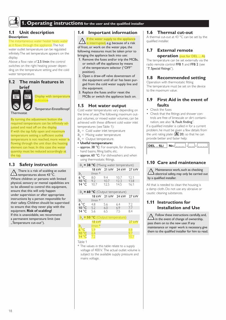
1.1 Unit descriptionDescription:Theinstantaneouswaterheaterheatswaterasitflowsthroughtheappliance.Thehotwateroutlettemperaturecanberegulatedinfinitely.Thesettemperatureappearsonthedisplay.Aboveaflowrateof2.5l/minthecontrolswitchesontherightheatingpowerdepen-dingonthetemperaturesettingandthecoldwatertemperature.
1.2 The main features in brief
DisplaywithtemperatureindicationTemperatur-Einstellknopf
Thermostat
Byturningtheadjustmentbuttontherequiredtemperaturecanbeinfinitelyad-justedandreadoffonthedisplay.Ifwiththetapfullyopenandmaximumtemperaturesettingasufficientoutlettemperatureisnotreached,morewaterisflowingthroughtheunitthantheheatingelementcanheat.Inthiscasethewaterquantitymustbereducedaccordinglyatthetap.
1.3 Safety instructionThereisariskofscaldingatoutlettemperaturesabove43°C.
Wherechildrenorpersonswithlimitedphysical,sensoryormentalcapabilitiesaretobeallowedtocontrolthisequipment,ensurethatthiswillonlyhappenundersupervisionorafterappropriateinstructionsbyapersonresponsiblefortheirsafety.Childrenshouldbesupervisedtoensurethattheyneverplaywiththeequipment.Risk of scalding!Ifthisisunavoidable,werecommendapermanenttemperaturelimit(see„Temperaturecut-out“).
1. Operating instructions for the user and the qualified installer
1.6 Thermal cut-outAthermalcut-outat43°Ccanbesetbythequalifiedinstaller.
1.7 External remote operation (notforDEL...A)
ThetemperaturecanbesetexternallyviatheradioremotecontrolFFB1andFFB2(see“7.Specialfittings”).
1.8 Recommended settingOperationwiththermostaticfittingThetemperaturemustbesetonthedevicetothemaximumvalue.
1.9 First Aid in the event of faults
• Checkthefuses• Checkthatthefittingsandshowercon-trolsarefreeoflimescaleordirtcontami-nation,seealso“6.Faultfinding”.
Ifaqualifiedinstalleriscalledinforacurrentproblem,hemustbegivenafewdetailsfromtheunitratingplate(A 20)sothathecanprovidebetterandfasterhelp:
DEL . . SLi Nr.: . . . . . . - . . . . - . . . . . .
1.10 Care and maintenance
Maintenancework,suchascheckingelectricalsafety,mayonlybecarriedout
byaqualifiedinstaller.
Allthatisneededtocleanthehousingisadampcloth.Donotuseanyabrasiveorcausticcleaningsubstances.
1.11 Instructions for Installation and Use
Followtheseinstructionscarefully,and,intheeventofchangeofownership,
passthemontothenewuser.Ifanymaintenanceorrepairworkisnecessary,givethemtothequalifiedinstallerforhimtoread.
1.4 Important informationIfthewatersupplytotheapplianceisinterrupted,e.g.becauseofarisk
offrost,orworkonthewaterpipe,thefollowingmeasuresmustbetakenpriortobringingtheappliancebackintouse:1. Removethefusesand/ortriptheMCBs,orswitchofftheappliancebymeansofthetemperatureselector(“OFF”position).
2. Openadraw-offvalvedownstreamoftheequipmentuntilallairhasbeenpur-gedfromthecoldwatersupplylineandtheequipment.
3. Replacethefusesand/orresettheMCBsorswitchtheappliancebackon.
1.5 Hot water outputColdwatertemperaturesvarydependingonthetimeofyear.Thefollowingmaximumout-putvolumes,ormixedwatervolumes,canbeachievedwiththesedifferentcoldwaterinlettemperatures(seeTable1):ϑ1= Coldwaterinlettemperatureϑ2= Mixingwatertemperatureϑ3= Outputtemperature.• Useful temperature:–approx.38°C:Forexample,forshowers,handbasins,fillingbaths,etc.
–approx.60°C:Fordishwashersandwhenusingthermostaticfittings.
ϑ2= 38 °C (Mixingwatertemperature)18kW 21kW 24kW 27kW
ϑ1 l/min*6°C 8.0 9.4 10.7 12.110°C 9.2 10.7 12.3 13.814°C 10.7 12.5 14.5 16.1
ϑ3= 60 °C (Outputtemperature)18kW 21kW 24kW 27kW
ϑ1 l/min*6°C 4.8 5.6 6.4 7.210°C 5.2 6.0 6.9 7.714°C 5.6 6.5 7.5 8.4
ϑ3= 50 °C (Outputtemperature)18kW 27kW
ϑ1 l/min*6°C 5.9 8.810°C 6.4 9.714°C 7.2 10.7
Table1*Thevaluesinthistablerelatetoasupplyvoltageof400V.Theactualoutletvolumeissubjecttotheavailablesupplypressureandmainsvoltage.
!
e l e c t ro n i c L C D e l e c t ro n i c L C D
1 Operatinginstructionsfortheuserandthequalifiedinstaller
!
!
18
english
2. Installation instructions for the qualified installer
!
!
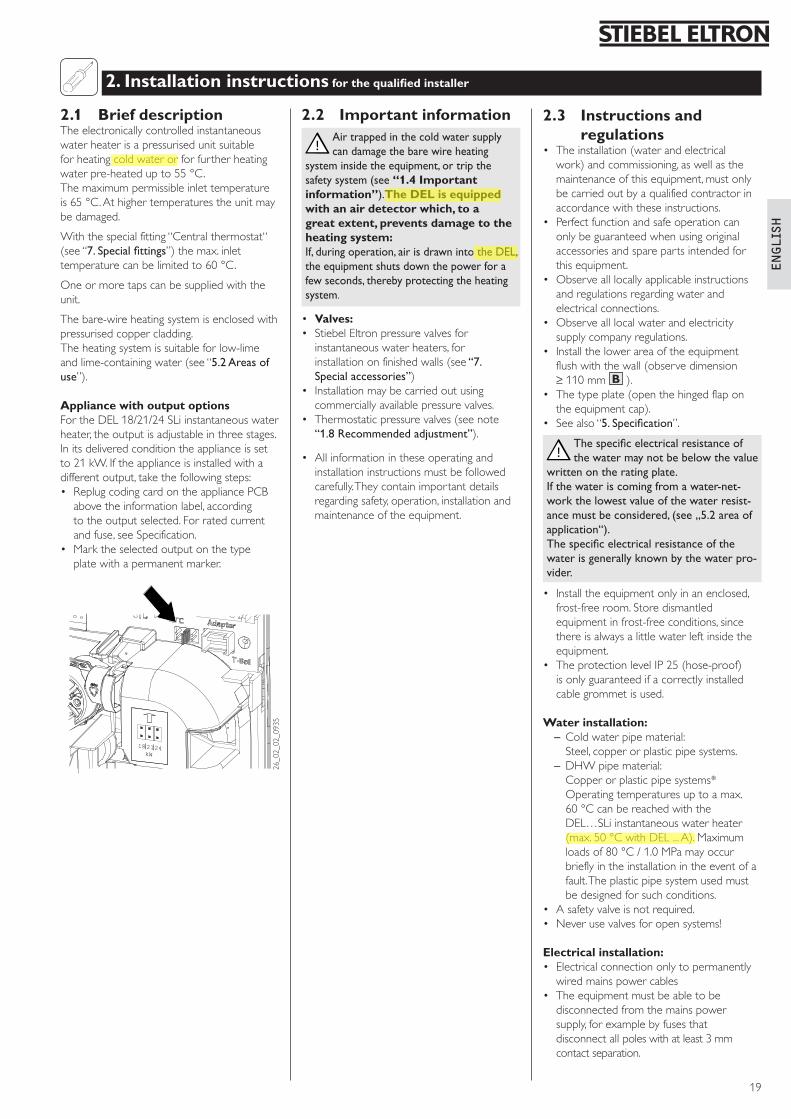
2.1 Brief descriptionTheelectronicallycontrolledinstantaneouswaterheaterisapressurisedunitsuitableforheatingcoldwaterorforfurtherheatingwaterpre-heatedupto55°C.Themaximumpermissibleinlettemperatureis65°C.Athighertemperaturestheunitmaybedamaged.
Withthespecialfitting“Centralthermostat“(see“7.Specialfittings”)themax.inlettemperaturecanbelimitedto60°C.
Oneormoretapscanbesuppliedwiththeunit.
Thebare-wireheatingsystemisenclosedwithpressurisedcoppercladding.Theheatingsystemissuitableforlow-limeandlime-containingwater(see“5.2Areasofuse”).
Appliance with output optionsFortheDEL18/21/24SLiinstantaneouswaterheater,theoutputisadjustableinthreestages.Initsdeliveredconditiontheapplianceissetto21kW.Iftheapplianceisinstalledwithadifferentoutput,takethefollowingsteps:• ReplugcodingcardontheappliancePCBabovetheinformationlabel,accordingtotheoutputselected.Forratedcurrentandfuse,seeSpecification.
• Marktheselectedoutputonthetypeplatewithapermanentmarker.
182124kW
26_02_02_0935
2.2 Important informationAirtrappedinthecoldwatersupplycandamagethebarewireheating
systeminsidetheequipment,ortripthesafetysystem(see“1.4 Important information”).The DEL is equipped with an air detector which, to a great extent, prevents damage to the heating system:If,duringoperation,airisdrawnintotheDEL,theequipmentshutsdownthepowerforafewseconds,therebyprotectingtheheatingsystem.
• Valves:• StiebelEltronpressurevalvesforinstantaneouswaterheaters,forinstallationonfinishedwalls(see“7.Specialaccessories”)
• Installationmaybecarriedoutusingcommerciallyavailablepressurevalves.
• Thermostaticpressurevalves(seenote“1.8Recommendedadjustment”).
• Allinformationintheseoperatingandinstallationinstructionsmustbefollowedcarefully.Theycontainimportantdetailsregardingsafety,operation,installationandmaintenanceoftheequipment.
2.3 Instructions and regulations
• Theinstallation(waterandelectricalwork)andcommissioning,aswellasthemaintenanceofthisequipment,mustonlybecarriedoutbyaqualifiedcontractorinaccordancewiththeseinstructions.
• Perfectfunctionandsafeoperationcanonlybeguaranteedwhenusingoriginalaccessoriesandsparepartsintendedforthisequipment.
• Observealllocallyapplicableinstructionsandregulationsregardingwaterandelectricalconnections.
• Observealllocalwaterandelectricitysupplycompanyregulations.
• Installthelowerareaoftheequipmentflushwiththewall(observedimension≥110mm B ).
• Thetypeplate(openthehingedflapontheequipmentcap).
• Seealso“5.Specification”.
Thespecificelectricalresistanceofthewatermaynotbebelowthevalue
writtenontheratingplate.Ifthewateriscomingfromawater-net-workthelowestvalueofthewaterresist-ancemustbeconsidered,(see„5.2areaofapplication“).Thespecificelectricalresistanceofthewaterisgenerallyknownbythewaterpro-vider.
• Installtheequipmentonlyinanenclosed,frost-freeroom.Storedismantledequipmentinfrost-freeconditions,sincethereisalwaysalittlewaterleftinsidetheequipment.
• TheprotectionlevelIP25(hose-proof)isonlyguaranteedifacorrectlyinstalledcablegrommetisused.
Water installation:–Coldwaterpipematerial: Steel,copperorplasticpipesystems.–DHWpipematerial: Copperorplasticpipesystems* Operatingtemperaturesuptoamax.60 °CcanbereachedwiththeDEL…SLiinstantaneouswaterheater(max.50°CwithDEL...A).Maximumloadsof80°C/1.0MPamayoccurbrieflyintheinstallationintheeventofafault.Theplasticpipesystemusedmustbedesignedforsuchconditions.
• Asafetyvalveisnotrequired.• Neverusevalvesforopensystems!
Electrical installation:• Electricalconnectiononlytopermanentlywiredmainspowercables
• Theequipmentmustbeabletobedisconnectedfromthemainspowersupply,forexamplebyfusesthatdisconnectallpoleswithatleast3mmcontactseparation.
2 Installationinstructionsforthequalifiedinstaller
19
!
!
3. Standard installation for the qualified installer Electro: UP – bottom; Water: UP
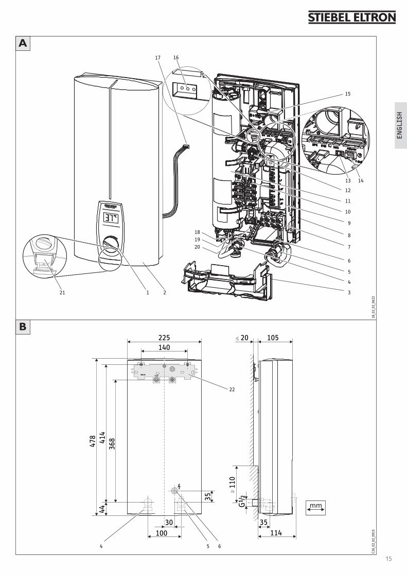
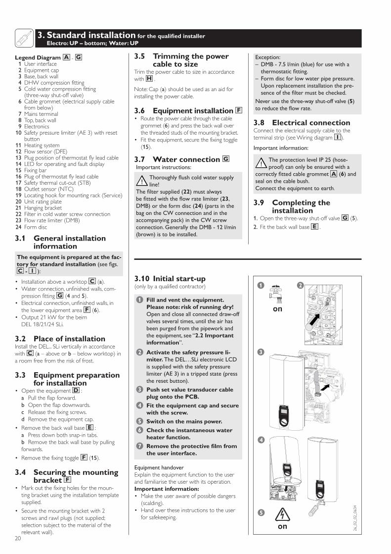
Legend Diagram A -G 1Userinterface 2 Equipmentcap 3 Base,backwall 4DHWcompressionfitting 5Coldwatercompressionfitting (three-wayshut-offvalve) 6Cablegrommet(electricalsupplycable
frombelow) 7Mainsterminal 8 Top,backwall 9 Electronics10 Safetypressurelimiter(AE3)withreset
button11Heatingsystem12 Flowsensor(DFE)13 Plugpositionofthermostatflyleadcable14 LEDforoperatingandfaultdisplay15 Fixingbar16 Plugofthermostatflyleadcable17 Safetythermalcut-out(STB)18 Outletsensor(NTC)19 Locatinghookformountingrack(Service)20 Unitratingplate21 Hangingbracket22 Filterincoldwaterscrewconnection23 Flowratelimiter(DMB)24 Formdisc
3.1 General installation information
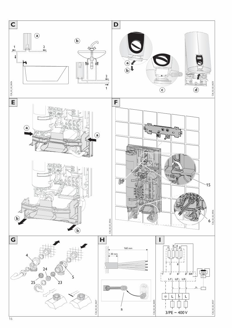
The equipment is prepared at the fac-tory for standard installation(seefigs.C - I ):
• InstallationaboveaworktopC (a).• Waterconnection,unfinishedwalls,com-pressionfittingG (4and5).
• Electricalconnection,unfinishedwalls,inthelowerequipmentarea F (6).
• Output21kWforthebeimDEL18/21/24SLi.
3.2 Place of installationInstalltheDEL...SLiverticallyinaccordancewithC (a–aboveorb–belowworktop)inaroomfreefromtheriskoffrost.
3.3 Equipment preparation for installation
• OpentheequipmentD : a Pulltheflapforward. b Opentheflapdownwards. c Releasethefixingscrews. d Removetheequipmentcap.
• Removethebackwallbase E : a Pressdownbothsnap-intabs. b Removethebackwallbasebypullingforwards.
• Removethefixingtoggle F (15).
3.4 Securing the mounting bracket F
• Markoutthefixingholesforthemoun-tingbracketusingtheinstallationtemplatesupplied.
• Securethemountingbracketwith2screwsandrawlplugs(notsupplied;selectionsubjecttothematerialoftherelevantwall).
3.5 Trimming the power cable to size
TrimthepowercabletosizeinaccordancewithH .
Note:Cap(a)shouldbeusedasanaidforinstallingthepowercable.
3.6 Equipment installation F• Routethepowercablethroughthecablegrommet(6)andpressthebackwalloverthethreadedstudsofthemountingbracket.
• Fittheequipment,securethefixingtoggle(15).
3.7 Water connection GImportantinstructions:
Thoroughlyflushcoldwatersupplyline!
Thefiltersupplied(22)mustalwaysbefittedwiththeflowratelimiter(23,DMB)ortheformdisc(24)(partsinthebagontheCWconnectionandintheaccompanyingpack)intheCWscrewconnection.GenerallytheDMB-12l/min(brown)istobeinstalled.
Exception:– DMB-7.5l/min(blue)forusewithathermostaticfitting.
– Formdiscforlowwaterpipepressure. Uponreplacementinstallationthepre-senceofthefiltermustbechecked.
Neverusethethree-wayshut-offvalve(5)toreducetheflowrate.
3.8 Electrical connectionConnecttheelectricalsupplycabletotheterminalstrip(seeWiringdiagram I ).
Importantinformation:
TheprotectionlevelIP25(hose-proof)canonlybeensuredwitha
correctlyfittedcablegrommetA (6)andsealonthecablebush.Connecttheequipmenttoearth.
3.9 Completing the installation
1.Openthethree-wayshut-offvalveG (5).
2.Fitthebackwallbase E .
3.10 Initial start-up(onlybyaqualifiedcontractor)
1 Fill and vent the equipment. Please note: risk of running dry! Openandcloseallconnecteddraw-offvalvesseveraltimes,untiltheairhasbeenpurgedfromthepipeworkandtheequipment,see“2.2 Important information”.
2 Activate the safety pressure li-miter. TheDEL…SLielectronicLCDissuppliedwiththesafetypressurelimiter(AE3)inatrippedstate(presstheresetbutton).
3 Push set value transducer cable plug onto the PCB.
4 Fit the equipment cap and secure with the screw.
5 Switch on the mains power.
6 Check the instantaneous water heater function.
7 Remove the protective film from the user interface.
EquipmenthandoverExplaintheequipmentfunctiontotheuserandfamiliarisetheuserwithitsoperation.Important information:• Maketheuserawareofpossibledangers(scalding).
• Handovertheseinstructionstotheuserforsafekeeping.
26_02_02_0634
1 2
3
4
5
3 Standardinstallationforthequalifiedinstaller
elect ronic com for t
20
english
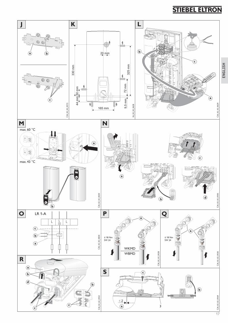
Alternative installations are shown in figures J - S .
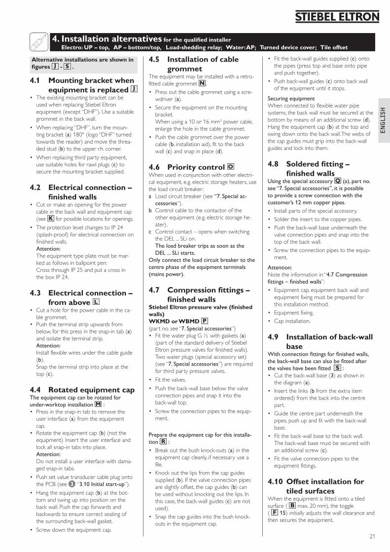
4.1 Mounting bracket when equipment is replaced J
• TheexistingmountingbracketcanbeusedwhenreplacingStiebelEltronequipment(except“DHF”).Useasuitablegrommetinthebackwall.
• Whenreplacing“DHF”,turnthemoun-tingbracket(a)180°(logo“DHF”turnedtowardsthereader)andmovethethrea-dedstud(b)totheupperr.h.corner.
• Whenreplacingthirdpartyequipment,usesuitableholesforrawlplugs(c)tosecurethemountingbracketsupplied.
4.2 Electrical connection – finished walls
• Cutormakeanopeningforthepowercableinthebackwallandequipmentcap(seeK forpossiblelocationsforopenings.
• TheprotectionlevelchangestoIP24(splash-proof)forelectricalconnectiononfinishedwalls.
Attention: Theequipmenttypeplatemustbemar-kedasfollowsinballpointpen:
CrossthroughIP25andputacrossintheboxIP24.
4.3 Electrical connection – from above L
• Cutaholeforthepowercableintheca-blegrommet.
• Pushtheterminalstripupwardsfrombelow,forthispressinthesnap-intab(a)andisolatetheterminalstrip.
Attention: Installflexiblewiresunderthecableguide(b).
Snaptheterminalstripintoplaceatthetop(c).
4.4 Rotated equipment capTheequipmentcapcanberotatedforunder-worktopinstallationM :• Pressinthesnap-intabtoremovetheuserinterface(a)fromtheequipmentcap.
• Rotatetheequipmentcap(b)(nottheequipment).Inserttheuserinterfaceandlockallsnap-intabsintoplace.
Attention: Donotinstallauserinterfacewithdama-gedsnap-intabs.
• PushsetvaluetransducercableplugontothePCB(see 3 “3.10Initialstart-up”).
• Hangtheequipmentcap(b)atthebot-tomandswingupintopositiononthebackwall.Pushthecapforwardsandbackwardstoensurecorrectseatingofthesurroundingback-wallgasket.
• Screwdowntheequipmentcap.
4.5 Installation of cable grommet
Theequipmentmaybeinstalledwitharetro-fittedcablegrommetN .• Pressoutthecablegrommetusingascre-wdriver(a).
• Securetheequipmentonthemountingbracket.
Whenusinga10or16mm²powercable,enlargetheholeinthecablegrommet.
• Pushthecablegrommetoverthepowercable(b,installationaid),fittothebackwall(c)andsnapinplace(d).
4.6 Priority control OWhenusedinconjunctionwithotherelectri-calequipment,e.g.electricstorageheaters,usetheloadcircuitbreaker:a Loadcircuitbreaker(see“7.Specialac-cessories“).
b Controlcabletothecontactoroftheotherequipment(e.g.electricstoragehe-ater),
c Controlcontact–openswhenswitchingtheDEL...SLion.
TheloadbreakertripsassoonastheDEL...SListarts.
Onlyconnecttheloadcircuitbreakertothecentrephaseoftheequipmentterminals(mainspower).
4.7 Compression fittings – finished walls
Stiebel Eltron pressure valve (finished walls)WKMD or WBMD P(partno.see“7.Specialaccessories”)• FitthewaterplugG½withgaskets(a)(partofthestandarddeliveryofStiebelEltronpressurevalvesforfinishedwalls).Twowaterplugs(specialaccessoryset)(see“7.Specialaccessories”)arerequiredforthirdpartypressurevalves.
• Fitthevalves.
• Pushtheback-wallbasebelowthevalveconnectionpipesandsnapitintotheback-walltop.
• Screwtheconnectionpipestotheequip-ment.
Preparetheequipmentcapforthisinstalla-tion R :• Breakoutthebushknock-outs(a)intheequipmentcapcleanly,ifnecessaryuseafile.
• Knockoutthelipsfromthecapguidessupplied(b).Ifthevalveconnectionpipesareslightlyoffset,thecapguides(b)canbeusedwithoutknockingoutthelips.Inthiscase,theback-wallguides(c)arenotused).
• Snapthecapguidesintothebushknock-outsintheequipmentcap.
• Fittheback-wallguidessupplied(c)ontothepipes(presstopandbaseontopipeandpushtogether).
• Pushback-wallguides(c)ontobackwalloftheequipmentuntilitstops.
SecuringequipmentWhenconnectedtoflexiblewaterpipesystems,thebackwallmustbesecuredatthebottombymeansofanadditionalscrew(d).Hangtheequipmentcap(b)atthetopandswingdownontothebackwall.Thewebsofthecapguidesmustgripintotheback-wallguidesandlockintothem.
4.8 Soldered fitting – finished walls
UsingthespecialaccessoryQ (a),partno.see“7.Specialaccessories”,itispossibletoprovideascrewconnectionwiththecustomer’s12mmcopperpipes.• Installpartsofthespecialaccessory.• Soldertheinserttothecopperpipes.• Pushtheback-wallbaseunderneaththevalveconnectionpipesandsnapintothetopofthebackwall.
• Screwtheconnectionpipestotheequip-ment.
Attention:Notetheinformationin“4.7Compressionfittings–finishedwalls”:• Equipmentcap,equipmentbackwallandequipmentfixingmustbepreparedforthisinstallationmethod.
• Equipmentfixing.• Capinstallation.
4.9 Installation of back-wall base
Withconnectionfittingsforfinishedwalls,theback-wallbasecanalsobefittedafterthevalveshavebeenfitted S :• Cuttheback-wallbase(3)asshowninthediagram(a).
• Insertthelinks(bfromtheextraitemordered)fromthebackintothecentrepart.
• Guidethecentrepartunderneaththepipes,pushupandfitwiththeback-wallbase.
• Fittheback-wallbasetothebackwall. Theback-wallbasemustbesecuredwithanadditionalscrew(c).
• Fitthevalveconnectionpipestotheequipmentfittings.
4.10 Offset installation for tiled surfaces
Whentheequipmentisfittedontoatiledsurface( B max.20mm),thetoggle( F 15)initiallyadjuststhewallclearanceandthensecurestheequipment.
4. Installation alternatives for the qualified installer Electro: UP – top, AP – bottom/top, Load-shedding relay; Water: AP; Turned device cover; Tile offset
4 Installationalternativesforthequalifiedinstaller
21
!
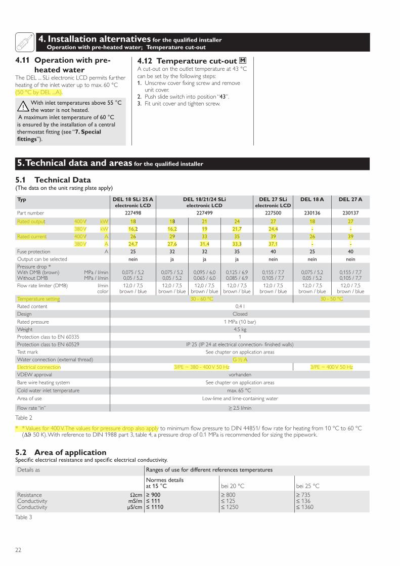
4.11 Operation with pre-heated water
TheDEL...SLielectronicLCDpermitsfurtherheatingoftheinletwateruptomax.60°C(50°CbyDEL...A).
Withinlettemperaturesabove55°Cthewaterisnotheated.
Amaximuminlettemperatureof60°Cisensuredbytheinstallationofacentralthermostatfitting(see“7. Special fittings”).
4.12 Temperature cut-out MAcut-outontheoutlettemperatureat43°Ccanbesetbythefollowingsteps:1. Unscrewcoverfixingscrewandremoveunitcover.
2. Pushslideswitchintoposition“43”.3. Fitunitcoverandtightenscrew.
4. Installation alternatives for the qualified installer Operation with pre-heated water; Temperature cut-out
5. Technical data and areas for the qualified installer
Table2
* *Valuesfor400V.ThevaluesforpressuredropalsoapplytominimumflowpressuretoDIN44851/flowrateforheatingfrom10°Cto60°C(∆ϑ50K).WithreferencetoDIN1988part3,table4,apressuredropof0.1MPaisrecommendedforsizingthepipework.
5.1 Technical Data (Thedataontheunitratingplateapply)
5.2 Area of applicationSpecificelectricalresistanceandspecificelectricalconductivity.
Detailsas Rangesofusefordifferentreferencestemperatures
Normesdetailsat15°C bei20°C bei25°C
ResistanceConductivityConductivity
ΩcmmS/mµS/cm
≥900≤111≤1110
≥800≤125≤1250
≥735≤136≤1360
Table3
5 Installationalternativesforthequalifiedinstaller
Typ DEL 18 SLi 25 Aelectronic LCD
DEL 18/21/24 SLielectronic LCD
DEL 27 SLielectronic LCD
DEL 18 A DEL 27 A
Partnumber 227498 227499 227500 230136 230137
Ratedoutput 400V kW 18 18 21 24 27 18 27380V kW 16,2 16,2 19 21,7 24,4 - -
Ratedcurrent 400V A 26 29 33 35 39 26 39380V A 24,7 27,6 31,4 33,3 37,1 - -
Fuseprotection A 25 32 32 35 40 25 40Outputcanbeselected nein ja ja ja nein nein neinPressuredrop*WithDMB(brown)WithoutDMB
MPa/l/minMPa/l/min
0,075/5,20,05/5,2
0,075/5,20,05/5,2
0,095/6,00,065/6,0
0,125/6,90,085/6,9
0,155/7,70,105/7,7
0,075/5,20,05/5,2
0,155/7,70,105/7,7
Flowratelimiter(DMB) l/mincolor
12,0/7,5brown/blue
12,0/7,5brown/blue
12,0/7,5brown/blue
12,0/7,5brown/blue
12,0/7,5brown/blue
12,0/7,5brown/blue
12,0/7,5brown/blue
Temperaturesetting 30-60°C 30-50°CRatedcontent 0,4lDesign Closed
Ratedpressure 1MPa(10bar)Weight 4.5kgProtectionclasstoEN60335 1ProtectionclasstoEN60529 IP25(IP24atelectricalconnection-finishedwalls)Testmark SeechapteronapplicationareasWaterconnection(externalthread) G½AElectricalconnection 3/PE~380-400V50Hz 3/PE~400V50HzVDEWapproval vorhanden
Barewireheatingsystem Seechapteronapplicationareas
Coldwaterinlettemperature max.65°C
Areaofuse Low-limeandlime-containingwater
Flowrate“in” ≥2.5l/min
22
english
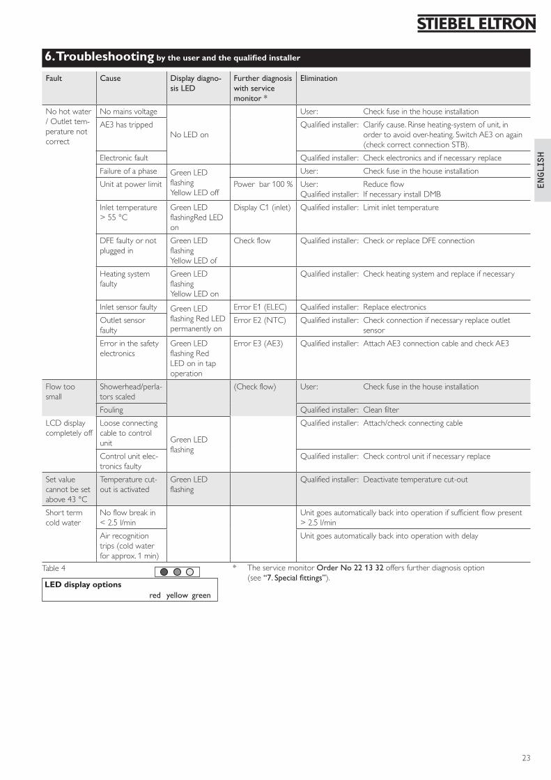
6. Troubleshooting by the user and the qualified installer
Fault Cause Displaydiagno-sisLED
Furtherdiagnosiswithservicemonitor*
Elimination
Nohotwater/Outlettem-peraturenotcorrect
Nomainsvoltage
NoLEDon
User: Checkfuseinthehouseinstallation
AE3hastripped Qualifiedinstaller : Clarifycause.Rinseheating-systemofunit,inordertoavoidover-heating.SwitchAE3onagain(checkcorrectconnectionSTB).
Electronicfault Qualifiedinstaller : Checkelectronicsandifnecessaryreplace
Failureofaphase GreenLEDflashingYellowLEDoff
User: Checkfuseinthehouseinstallation
Unitatpowerlimit Powerbar100% User: ReduceflowQualifiedinstaller : IfnecessaryinstallDMB
Inlettemperature>55°C
GreenLEDflashingRedLEDon
DisplayC1(inlet) Qualifiedinstaller : Limitinlettemperature
DFEfaultyornotpluggedin
GreenLEDflashingYellowLEDof
Checkflow Qualifiedinstaller : CheckorreplaceDFEconnection
Heatingsystemfaulty
GreenLEDflashingYellowLEDon
Qualifiedinstaller : Checkheatingsystemandreplaceifnecessary
Inletsensorfaulty GreenLEDflashingRedLEDpermanentlyon
ErrorE1(ELEC) Qualifiedinstaller : Replaceelectronics
Outletsensorfaulty
ErrorE2(NTC) Qualifiedinstaller : Checkconnectionifnecessaryreplaceoutletsensor
Errorinthesafetyelectronics
GreenLEDflashingRedLEDonintapoperation
ErrorE3(AE3) Qualifiedinstaller : AttachAE3connectioncableandcheckAE3
Flowtoosmall
Showerhead/perla-torsscaled
(Checkflow) User: Checkfuseinthehouseinstallation
Fouling Qualifiedinstaller : Cleanfilter
LCDdisplaycompletelyoff
Looseconnectingcabletocontrolunit GreenLED
flashing
Qualifiedinstaller : Attach/checkconnectingcable
Controlunitelec-tronicsfaulty
Qualifiedinstaller : Checkcontrolunitifnecessaryreplace
Setvaluecannotbesetabove43°C
Temperaturecut-outisactivated
GreenLEDflashing
Qualifiedinstaller : Deactivatetemperaturecut-out
Shorttermcoldwater
Noflowbreakin<2.5l/min
Unitgoesautomaticallybackintooperationifsufficientflowpresent>2.5l/min
Airrecognitiontrips(coldwaterforapprox.1min)
Unitgoesautomaticallybackintooperationwithdelay
Table4 * TheservicemonitorOrderNo221332offersfurtherdiagnosisoption(see“7.Specialfittings”).
LED display options red yellow green
6 Troubleshootingbytheuserandthequalifiedinstaller
23
7. Special accessories
7 Specialaccessories
8 Guarantee9 EnvironmentandRecycling
24
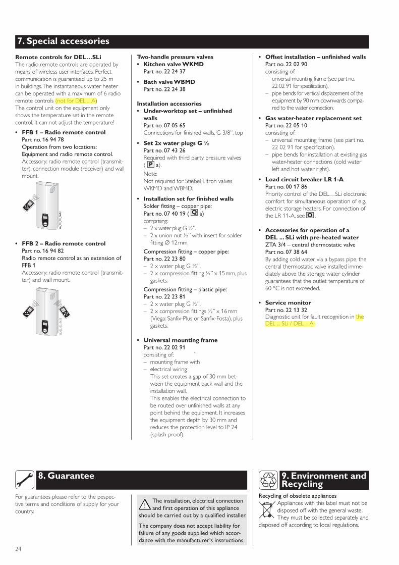
Remote controls for DEL…SLiTheradioremotecontrolsareoperatedbymeansofwirelessuserinterfaces.Perfectcommunicationisguaranteedupto25minbuildings.Theinstantaneouswaterheatercanbeoperatedwithamaximumof6radioremotecontrols(notforDEL...A)Thecontrolunitontheequipmentonlyshowsthetemperaturesetintheremotecontrol,itcannotadjustthetemperature!
• FFB 1 – Radio remote control Partno.169478Operationfromtwolocations:Equipmentandradioremotecontrol.Accessory:radioremotecontrol(transmit-ter),connectionmodule(receiver)andwallmount.
• FFB 2 – Radio remote controlPartno.169482RadioremotecontrolasanextensionofFFB1Accessory:radioremotecontrol(transmit-ter)andwallmount.
Two-handle pressure valves• Kitchen valve WKMDPartno.222437
• Bath valve WBMDPartno.222438
Installation accessories• Under-worktop set – unfinished
wallsPartno.070565Connectionsforfinishedwalls,G3/8”,top
• Set 2x water plugs G ½Partno.074326Requiredwiththirdpartypressurevalves( P a).
Note:NotrequiredforStiebelEltronvalvesWKMDandWBMD.
• Installation set for finished walls Solderfitting–copperpipe: Partno.074019(Q a)comprising:– 2xwaterplugG½”.– 2xunionnut½”withinsertforsolderfittingØ12mm.
Compressionfitting–copperpipe: Partno.222380– 2xwaterplugG½”.– 2xcompressionfitting½”x15mm,plusgaskets.
Compressionfitting–plasticpipe: Partno.222381– 2xwaterplugG½”.– 2xcompressionfittings½”x16mm(Viega:Sanfix-PlusorSanfix-Fosta),plusgaskets.
• Universal mounting framePartno.220291consistingof:– mountingframewith– electricalwiring Thissetcreatesagapof30mmbet-weentheequipmentbackwallandtheinstallationwall.
Thisenablestheelectricalconnectiontoberoutedoverunfinishedwallsatanypointbehindtheequipment.Itincreasestheequipmentdepthby30mmandreducestheprotectionleveltoIP24(splash-proof).
• Offset installation – unfinished wallsPartno.220290consistingof:– universalmountingframe(seepartno.220291forspecification).
– pipebendsforverticaldisplacementoftheequipmentby90mmdownwardscompa-redtothewaterconnection.
• Gas water-heater replacement setPartno.220510consistingof:– universalmountingframe(seepartno.220291forspecification).
– pipebendsforinstallationatexistinggaswater-heaterconnections(coldwaterleftandhotwaterright).
• Load circuit breaker LR 1-APartno.001786PrioritycontroloftheDEL…SLielectroniccomfortforsimultaneousoperationofe.g.electricstorageheaters.ForconnectionoftheLR11-A,seeO .
• Accessories for operation of a DEL ... SLi with pre-heated waterZTA3/4–centralthermostaticvalvePartno.073864Byaddingcoldwaterviaabypasspipe,thecentralthermostaticvalveinstalledimme-diatelyabovethestoragewatercylinderguaranteesthattheoutlettemperatureof60°Cisnotexceeded.
• Service monitor Partno.221332 DiagnosticunitforfaultrecognitionintheDEL...SLi/DEL...A..
ele
ctronic
com
fort
26_02_02_0632
26_02_02_0632
ele
ctr
onic
com
fort
ele
ctronic
com
fort
26_02_02_0633
9. Environment and Recycling
RecyclingofobseleteappliancesApplianceswiththislabelmustnotbedisposedoffwiththegeneralwaste.Theymustbecollectedseparatelyand
disposedoffaccordingtolocalregulations.
Forguaranteespleaserefertothepespec-tivetermsandconditionsofsupplyforyourcountry.
Theinstallation,electricalconnectionandfirstoperationofthisappliance
shouldbecarriedoutbyaqualifiedinstaller.
Thecompanydoesnotacceptliabilityforfailureofanygoodssuppliedwhichaccor-dancewiththemanufacturer‘sinstructions.
!
8. Guarantee

english
25