ge2111 engineering graphics l2 t3 p0 total 5 engineering graphics l2 t3 p0 total 5 aim to develop...
TRANSCRIPT
GE2111 ENGINEERING GRAPHICS L2 T3 P0 Total 5 AIM To develop graphic skills in students.
OBJECTIVES To develop in students graphic skill for communication of concepts, ideas and
design of engineering products and expose them to existing national standards
related to technical drawings.
Concepts and conventions (Not for Examination) 1
Importance of graphics in engineering applications – Use of drafting instruments –
BIS conventions and specifications – Size, layout and folding of drawing sheets –
Lettering and dimensioning.
UNIT IPLANE CURVES AND FREE HAND SKETCHING 15 Curves used in engineering practices: Conics – Construction of ellipse, Parabola and hyperbola by eccentricity method –
Construction of cycloid – construction of involutes of squad and circle – Drawing of
tangents and normal to the above curves. Free hand sketching: Representation of Three Dimensional objects – General principles of orthographic
projection – Need for importance of multiple views and their placement – First
angle projection – layout views – Developing visualization skills through free hand
sketching of multiple views from pictorial views of objects.
UNIT IIPROJECTION OF POINTS, LINES AND PLANE SURFACES 14
Projection of points and straight lines located in the first quadrant – Determination
of true lengths and true inclinations – Projection of polygonal surface and circular
lamina inclined to both reference planes.
UNIT III PROJECTION OF SOLIDS 15
Projection of simple solids like prisms, pyramids, cylinder and cone when the axis is
inclined to one reference plane by change of position method.
UNIT IV SECTION OF SOLIDS AND DEVELOPMENT OF SURFACES 15
Sectioning of above solids in simple vertical position by cutting planes inclined to
one reference plane and perpendicular to the other – Obtaining true shape of
section. Development of lateral surfaces of simple and truncated solids – Prisms, pyramids,
cylinders and cones – Development of lateral surfaces of solids with cylindrical
cutouts, perpendicular to the axis. 1
UNIT VISOMETRIC AND PERSPECTIVE PROJECTIONS 15
Principles of isometric projection – isometric scale – isometric projections of simple
solids, truncated prisms, pyramids, cylinders and cones. Perspective projection of prisms, pyramids and cylinders by visual ray method.
TOTAL: 75 PERIODS
TEXT BOOKS 1. S. Gowri and T. Jeyapoovan, “Engineering Graphics”, Vikas
Publishing House Pvt Ltd., First Edition, 2011.
2. N.D. Bhatt, “Engineering Drawing” Charotar Publishing House, 46th Edition, (2003).
REFERENCES 1. K.V. Natrajan, “A text book of Engineering Graphics”, Dhanalakshmi
Publishers, Chennai (2006). 2. M.S. Kumar, “Engineering Graphics”, D.D. Publications, (2007). 3. K. Venugopal & V. Prabhu Raja, “Engineering Graphics”, New Age
International (P) Limited (2008).
4. M.B. Shah and B.C. Rana, “Engineering Drawing”, Pearson Education (2005).
5. K. R. Gopalakrishnana, “Engineering Drawing” (Vol.I&II), Subhas Publications
(1998).
6. Dhananjay A.Jolhe, “Engineering Drawing with an introduction to AutoCAD”
Tata McGraw Hill Publishing Company Limited (2008). 7. Basant Agarwal and Agarwal C.M., “Engineering Drawing”, Tata McGraw Hill
Publishing Company Limited, New Delhi, (2008). Publication of Bureau of Indian Standards: 1. IS 10711 – 2001: Technical products Documentation – Size and lay out of drawing
sheets. 2. IS 9609 (Parts 0 & 1) – 2001: Technical products Documentation – Lettering. 3. IS 10714 (Part 20) – 2001 & SP 46 – 2003: Lines for technical drawings. 4. IS 11669 – 1986 & SP 46 – 2003: Dimensioning of Technical Drawings. 5. IS 15021 (Parts 1 to 4) – 2001: Technical drawings – Projection Methods.
Special points applicable to University Examinations on Engineering Graphics:
1. There will be five questions, each of either or type covering all units of the
syllabus.
2. All questions will carry equal marks of 20 each making a total of 100. 3. The answer paper shall consist of drawing sheets of A3 size only. The students
will be permitted to use appropriate scale to fit solution within A3 size.
4. Whenever the total number of candidates in a college exceeds 150, the University
Examination in that college will be conducted in two sessions (FN and AN on
the same day) for 50 percent of student (approx) at a time. 2

GENERAL INSTRUCTIONS • Each student is instructed to have this tutorial book during the theory class and also for
practice class. • The student should have a separate long size unruled drawing note book for this subject
for taking class notes.
• Each student should have a mini drafter, set squares, drawing sheet, padding sheet,
drawing pencils (2H, H, HB pencils), drawing clips, cello tape, sharpener, eraser during
each practice class. Borrowing of those items will not be encouraged. • The student should complete the tutorial problems within the stipulated time period and
the same should be submitted to the course instructor after the completion of tutorials in
each and every chapter.
• The student has to maintain a separate file for this course for filing the completed drawing
sheets. • The students should reach the drawing practice class in time. Late comers will not be given
attendance. However those students may be allowed inside the drawing hall for practising.
• The students should seat in the drawing hall as per their roll numbers and they should not
move from one place to another place . • The students should do a minimum number of problems in the practice class specified by
the respective course teacher at that time. • Copying of problems from others will not be permitted. • The special class for this subject will be arranged and will be displayed in the Mechanical
Engineering Department notice board, regarding the resource persons and the coaching
class room.
• The weak students and absentee students can make use of the special class for better
understanding of the subject.
• The students who are unable to finish the tutorial problems in the regular practice
classshould complete the same in their home and submit the same to the Faculty incharge
in time.
3

Teaching Schedule
Continuous
Topics to be covered
Assignment Assessment Test
Week Submission Portions
No (Tentative)
Lecture Practice
( 2 Hrs) (3 Hrs)
1
Introduction, Lettering and
Dimensioning, Title Block, Tutorial I
Usage of Drawing Pencils
2 Projection of Points, Straight
Tutorial II Submission of
Lines (Simple Cases) Tutorial I
Test – 1
3 Projection of Straight Lines
Tutorial II Submission of
(Special Cases) Tutorial II
4 Projection of Straight Lines
Tutorial III
(Special Cases)
5 Projection of Planes
Tutorial III Submission of
Tutorial III
6 Projection of Planes Tutorial IV
7 Projection of Solids (Simple
Tutorial V Submission of
Case) Tutorial IV
8 Projection of solids (Special
Tutorial V Submission of
Case) Tutorial V
9 Projection of Solids (Special
Tutorial VI
Test – 2
Case)
10 Section of Solids
Tutorial VII Submission of
Tutorial VI
11 Development of Surfaces
Tutorial VIII Submission of
Tutorial VII
12 Isometric Projection
Tutorial IX Submission of
Tutorial VIII
13 Perspective Projection
Tutorial X Submission of
Tutorial IX
14 Conic Sections & Special
Tutorial XI Submission of
Test – 3
Curves Tutorial X
15 Free Hand Sketching
Tutorial XII Submission of
Tutorial XI
16 Summary Submission of
Tutorial XII
4
Introduction
Standard Sizes of Drawing Board
S.No Designation Length X Width
Thickness To be used with
(in mm) sheet sizes
1 D00 1525 X 1220 22 -
2 D0 1270 X 920 22 A0
3 D1 920 X 650 22 A1
4 D2 650 X 470 22 A2
5 D3 500 X 350 22 A3
Standard sizes of drawing sheets
S. No Designation Dimensions (in mm)
1 A0 841 X 1189
2 A1 594 X 841
3 A2 420 X 594
4 A3 297 X 420
5 A4 210 X 297
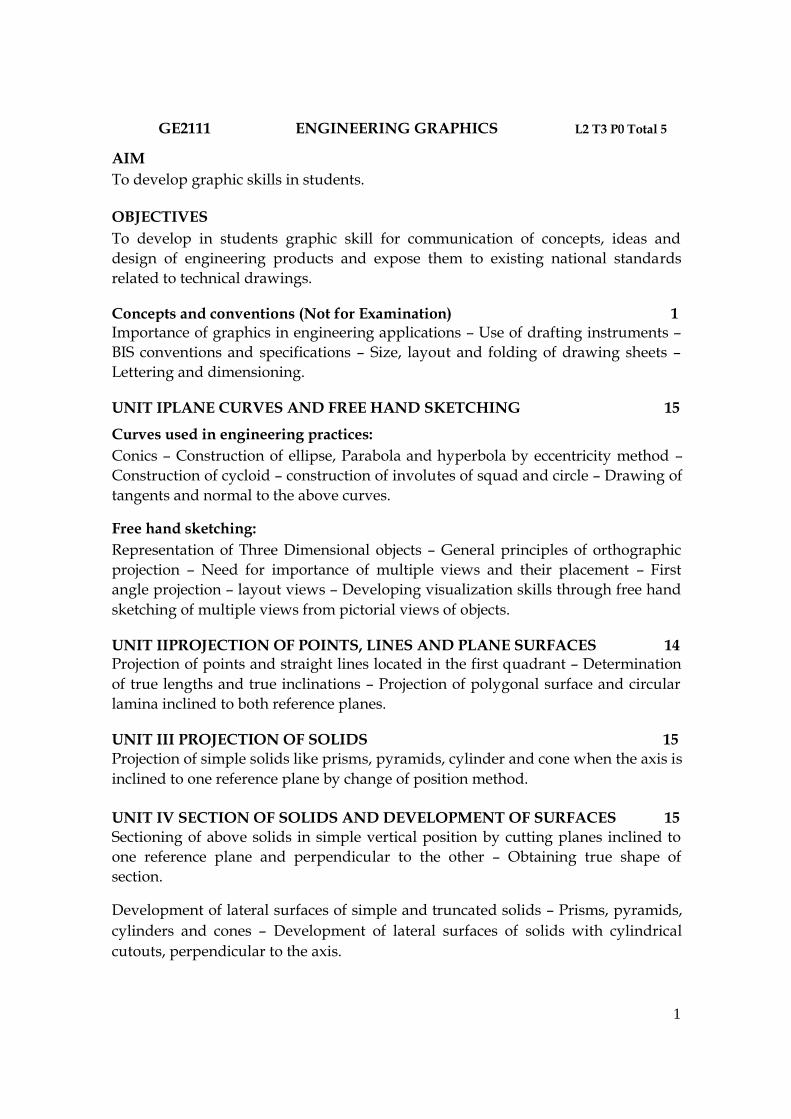
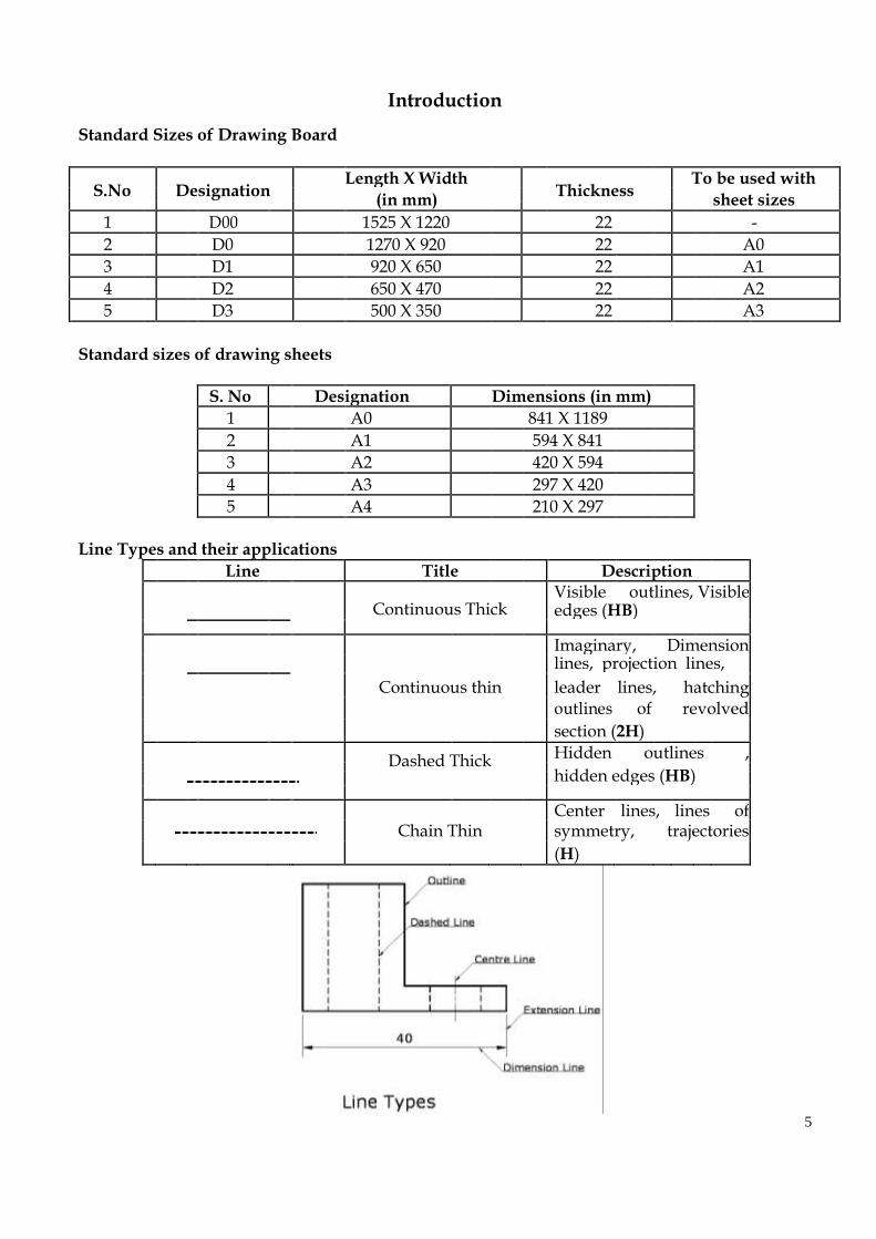
Line Types and their applications
Line Title Description
Continuous Thick
Visible outlines, Visible
edges (HB)
Imaginary, Dimension
Continuous thin
lines, projection lines,
leader lines, hatching
outlines of revolved
section (2H)
Dashed Thick Hidden outlines ,
hidden edges (HB)
Center lines, lines of
Chain Thin symmetry, trajectories
(H)
5

Lettering
6

Dimensioning Dimensioning A drawing means little without full dimensioning. Each dimension should appear only once. No
calculation of dimensions should be necessary.
I
Indicating dimensional values
Indicating radius on an arc
on oblique dimension lines
7

8
Tutorial – I
Lettering & Dimensioning Practice Submission date:-
1) Do the lettering Practice for upper case alphabets and numerals. Take the height of the letter
as 10 mm. Do it for two times. 2) Do the lettering practice for lower case letters. Take the height of the letter as 5 mm. Do it for
two times 3) Write the following sentence in vertical Capitals of Height 10 mm.
DRAWING IS THE UNIVERSAL LANGUAGE OF ENGINEERS
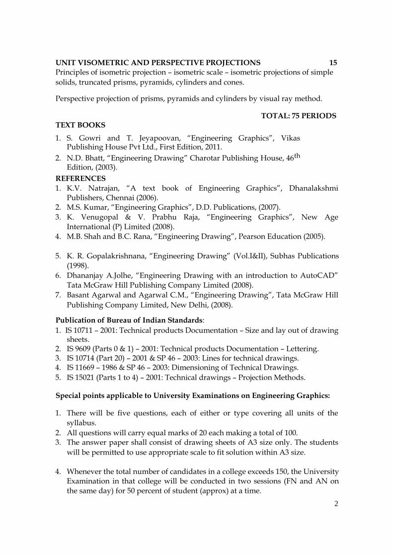
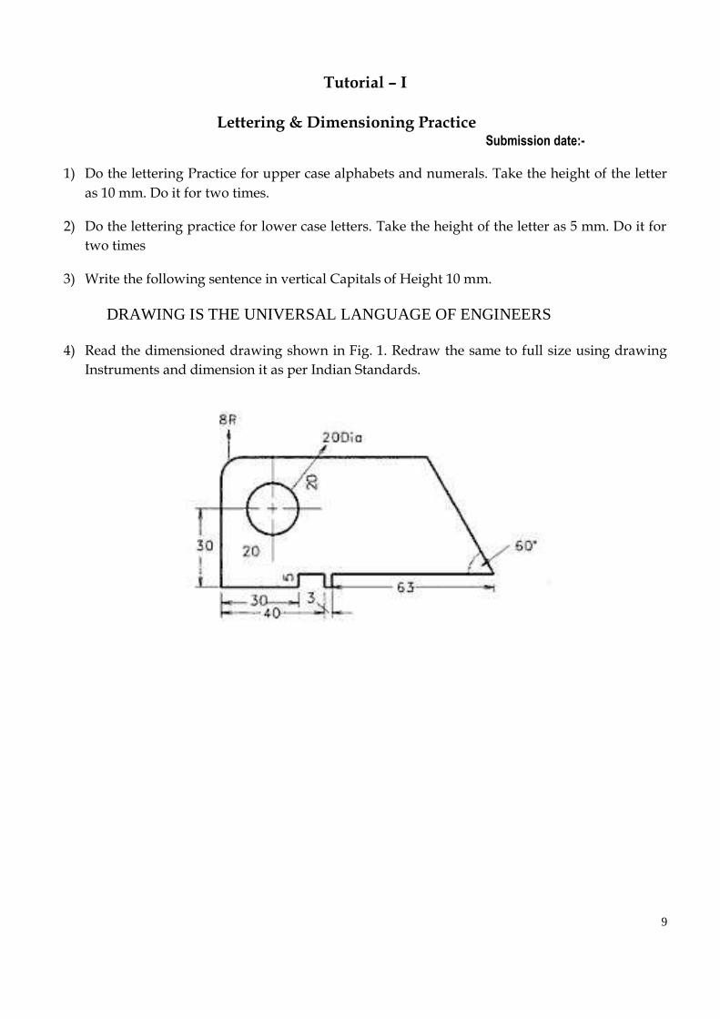
4) Read the dimensioned drawing shown in Fig. 1. Redraw the same to full size using drawing
Instruments and dimension it as per Indian Standards. 9
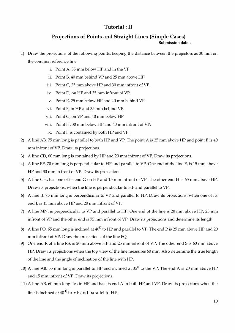
Tutorial : II
Projections of Points and Straight Lines (Simple Cases) Submission date:-
1) Draw the projections of the following points, keeping the distance between the projectors as 30 mm on
the common reference line.
i. Point A, 35 mm below HP and in the VP
ii. Point B, 40 mm behind VP and 25 mm above HP
iii. Point C, 25 mm above HP and 30 mm infront of VP.
iv. Point D, on HP and 35 mm infront of VP.
v. Point E, 25 mm below HP and 40 mm behind VP.
vi. Point F, in HP and 35 mm behind VP.
vii. Point G, on VP and 40 mm below HP
viii. Point H, 30 mm below HP and 40 mm infront of VP.
ix. Point I, is contained by both HP and VP. 2) A line AB, 75 mm long is parallel to both HP and VP. The point A is 25 mm above HP and point B is 40
mm infront of VP. Draw its projections.
3) A line CD, 60 mm long is contained by HP and 20 mm infront of VP. Draw its projections. 4) A line EF, 70 mm long is perpendicular to HP and parallel to VP. One end of the line E, is 15 mm above
HP and 30 mm in front of VP. Draw its projections. 5) A line GH, has one of its end G on HP and 15 mm infront of VP. The other end H is 65 mm above HP.
Draw its projections, when the line is perpendicular to HP and parallel to VP.
6) A line IJ, 75 mm long is perpendicular to VP and parallel to HP. Draw its projections, when one of its
end I, is 15 mm above HP and 20 mm infront of VP. 7) A line MN, is perpendicular to VP and parallel to HP. One end of the line is 20 mm above HP, 25 mm
infront of VP and the other end is 75 mm infront of VP. Draw its projections and determine its length.
8) A line PQ, 65 mm long is inclined at 400 to HP and parallel to VP. The end P is 25 mm above HP and 20
mm infront of VP. Draw the projections of the line PQ. 9) One end R of a line RS, is 20 mm above HP and 25 mm infront of VP. The other end S is 60 mm above
HP. Draw its projections when the top view of the line measures 60 mm. Also determine the true length
of the line and the angle of inclination of the line with HP. 10) A line AB, 55 mm long is parallel to HP and inclined at 350 to the VP. The end A is 20 mm above HP
and 15 mm infront of VP. Draw its projections 11) A line AB, 60 mm long lies in HP and has its end A in both HP and VP. Draw its projections when the
line is inclined at 40 0 to VP and parallel to HP. 10

11
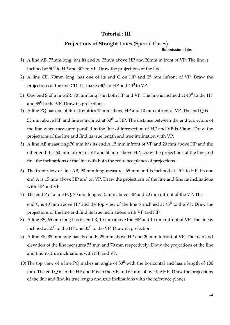
Tutorial : III
Projections of Straight Lines (Special Cases) Submission date:-
1) A line AB, 75mm long, has its end A, 25mm above HP and 20mm in front of VP. The line is
inclined at 50o to HP and 30o to VP. Draw the projections of the line. 2) A line CD, 70mm long, has one of its end C on HP and 25 mm infront of VP. Draw the
projections of the line CD if it makes 300 to HP and 400 to VP.
3) One end S of a line SR, 70 mm long is in both HP and VP. The line is inclined at 400 to the HP
and 350 to the VP. Draw its projections. 4) A line PQ has one of its extremities 15 mm above HP and 10 mm infront of VP. The end Q is
55 mm above HP and line is inclined at 300 to HP. The distance between the end projectors of
the line when measured parallel to the line of intersection of HP and VP is 50mm. Draw the
projections of the line and find its true length and true inclination with VP. 5) A line AB measuring 70 mm has its end A 15 mm infront of VP and 20 mm above HP and the
other end B is 60 mm infront of VP and 50 mm above HP. Draw the projections of the line and
fine the inclinations of the line with both the reference planes of projections.
6) The front view of line AB, 90 mm long measures 65 mm and is inclined at 45 0 to HP. Its one
end A is 15 mm above HP and on VP. Draw the projections of the line and fine its inclinations
with HP and VP. 7) The end P of a line PQ, 70 mm long is 15 mm above HP and 20 mm infront of the VP. The
end Q is 40 mm above HP and the top view of the line is inclined at 450 to the VP. Draw the
projections of the line and find its true inclinations with VP and HP. 8) A line RS, 65 mm long has its end R, 15 mm above the HP and 15 mm infront of VP. The line is
inclined at 550 to the HP and 350 to the VP. Draw its projections.
9) A line EF, 85 mm long has its end E, 25 mm above HP and 20 mm infront of VP. The plan and
elevation of the line measures 55 mm and 70 mm respectively. Draw the projections of the line
and find its true inclinations with HP and VP.
10) The top view of a line PQ makes an angle of 300 with the horizontal and has a length of 100
mm. The end Q is in the HP and P is in the VP and 65 mm above the HP. Draw the projections
of the line and find its true length and true inclinations with the reference planes.
12

11) The plan and elevation of a line AB are inclined at 35o and 50o to the XY line respectively. One
end of the line is touching both HP and VP. The other end is 50mm above HP. Find its true
length and true angle of inclinations with HP and VP. 12) The end P of a line PQ is 50 mm away from both the reference planes and the other end Q is 20
mm above HP and 25 mm infront of VP. Draw the projections of the line PQ and find its true
inclinations with HP and VP if the length of the line is 60 mm.
13) Draw the projections of a straight line AB, 100 mm long, inclined at 450 to HP and 300 to VP.
The end A is in HP and the end B is in VP. 14) A line 100 mm long has its lower end in HP and the upper end in VP. Its plan and elevation
measure 80 mm and 70 mm respectively. Draw the projections of the line and find its True
inclinations with HP and VP. 15) The mid point of line AB, 80 mm long is 80 mm above HP and 50 mm infront of VP. The line is
inclined at 300 to HP and 450 to VP. Draw its projections.
16) End A of the line AB of 75 mm long is 50 mm infront of VP and 15 mm above HP. End B is 15
mm infront of VP and above HP. The top view of the line is measured to be 50 mm long.
Determine the length of its elevation and the true inclination of the line.
17) The distance between the end projectors passing through the end points of a line AB is 60
mm. The end A is 15 mm above HP and 10 mm infront of VP. The end B is 35mm infront of
VP. The line AB appears 70 mm long in the front view. Complete the projections by
trapezoidal method and find the true length of the line and its inclinations with HP and VP.
13
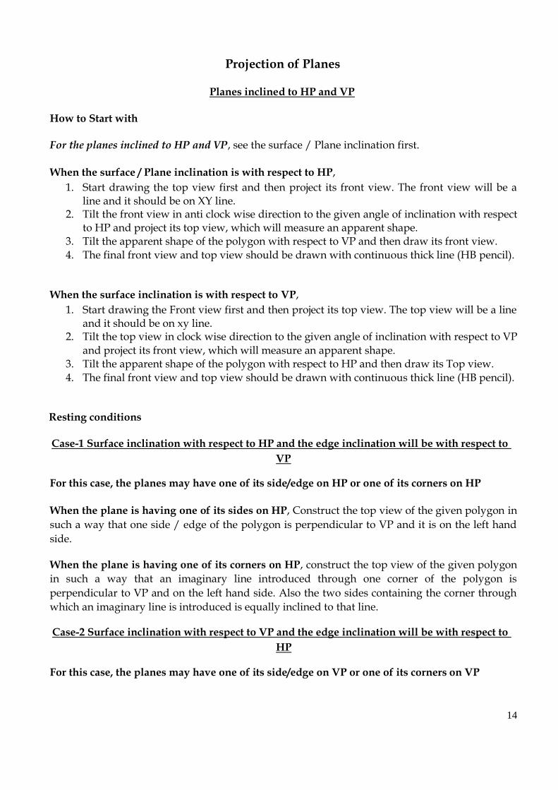
Projection of Planes
Planes inclined to HP and VP
How to Start with
For the planes inclined to HP and VP, see the surface / Plane inclination first.
When the surface / Plane inclination is with respect to HP, 1. Start drawing the top view first and then project its front view. The front view will be a
line and it should be on XY line. 2. Tilt the front view in anti clock wise direction to the given angle of inclination with respect
to HP and project its top view, which will measure an apparent shape. 3. Tilt the apparent shape of the polygon with respect to VP and then draw its front view. 4. The final front view and top view should be drawn with continuous thick line (HB pencil).
When the surface inclination is with respect to VP, 1. Start drawing the Front view first and then project its top view. The top view will be a line
and it should be on xy line. 2. Tilt the top view in clock wise direction to the given angle of inclination with respect to VP
and project its front view, which will measure an apparent shape. 3. Tilt the apparent shape of the polygon with respect to HP and then draw its Top view. 4. The final front view and top view should be drawn with continuous thick line (HB pencil).
Resting conditions
Case-1 Surface inclination with respect to HP and the edge inclination will be with respect to
VP For this case, the planes may have one of its side/edge on HP or one of its corners on HP
When the plane is having one of its sides on HP, Construct the top view of the given polygon in
such a way that one side / edge of the polygon is perpendicular to VP and it is on the left hand
side.
When the plane is having one of its corners on HP, construct the top view of the given polygon
in such a way that an imaginary line introduced through one corner of the polygon is
perpendicular to VP and on the left hand side. Also the two sides containing the corner through
which an imaginary line is introduced is equally inclined to that line. Case-2 Surface inclination with respect to VP and the edge inclination will be with respect to
HP For this case, the planes may have one of its side/edge on VP or one of its corners on VP
14
When the plane is having one of its sides on VP, construct the front view of the given polygon
in such a way that one side / edge of the polygon is perpendicular to HP and it is on the left hand
side.
When the plane is having one of its corners on HP, construct the top view of the given polygon
in such a way that an imaginary line introduced through one corner of the polygon is
perpendicular to HP and on the left hand side. Also the two sides containing the corner through
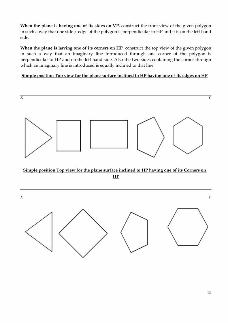
which an imaginary line is introduced is equally inclined to that line. Simple position Top view for the plane surface inclined to HP having one of its edges on HP
X Y
Simple position Top view for the plane surface inclined to HP having one of its Corners on
HP
X Y
15

Simple position Front view for the plane surface inclined to VP having one of its edges on VP
X Y
Simple position Front view for the plane surface inclined to HP having one of its Corners on
HP
X Y
Case – III (Refer problem no’s 12 and 13 in tutorial sheet no- 4): When the plane surfaces is
inclined to both HP and VP, then their summation of their angles will be 900. In this case the
inclination angles can be seen only in the side view. For this type of problems,
1. Start with either drawing the front view or top view first. 2. Project its side view, which will be a line. 3. Tilt the side view to the given angle of inclinations with respect to HP and VP 4. Draw its front view and top view, which will measure an apparent shape.
Indirect Problems
The problems for which the surface inclination with respect to HP and VP is not given, the
apparent shape dimensions and in which view this apparent shape is obtained will be given. For
this kind of problems, the following hint will be useful
16
1. When the apparent shape is obtained in the top view, then the plane will be inclined to HP
(eg. The top view of rectangular plane 50 X 30 mm resting on the HP on one of its shorter
edges is a square of side 30 mm). For this type of problem
a. Start drawing the top view first and then project is front view, which will be a
line b. Since the apparent shape dimensions are given, in the second stage construct the
apparent shape of the polygon in the top view for the given dimensions and then find the angle of inclination of the front view
c. Tilt the apparent shape of the polygon with respect to VP and then draw its front view.
d. The final front view and top view should be drawn with continuous thick line
(HB pencil).
2. When the apparent shape is obtained in the front view, then the plane will be inclined to
VP (eg. The front view of the circular lamina of 80 mm diameter having one of its corners
on VP is an ellipse of major axis 80 mm and minor axis 40 mm)
a. Start drawing the front view first and then project is top view, which will be a line
b. Since the apparent shape dimensions are given, in the second stage construct the
apparent shape of the polygon in the front view for the given dimensions and then
find the angle of inclination of the top view c. Tilt the apparent shape of the polygon with respect to HP and then draw its Top
view. d. The final front view and top view should be drawn with continuous thick line (HB
pencil).
17
Tutorial : IV
Projection of Planes Submission date:-
1) A Square lamina of side 40 mm has its surface parallel to and 20 mm above HP. Draw its
projections when one of its sides is inclined at 300 to the VP. 2) A Hexagonal plate of 30 mm side has its surface parallel to VP and 20 mm infront of it.
Draw the projections when one of its sides is perpendicular to HP.
3) A Pentagonal plane of side 30 mm is parallel to VP and perpendicular to HP. Draw its
projections when one of its corners is on HP and the side containing the resting corner is
inclined at 250 to HP. 4) A Hexagonal plate with 30 mm side has its surface perpendicular to VP and inclined at
450 to HP. Draw its projections when one of its sides is on HP and the corner nearer to the
VP is 20 mm infront of it.
5) A Circular plane of 60 mm diameter has its plane vertical and inclined at 400 to VP. Its
centre is 40 mm above HP and 35 mm infront of VP. Draw its projections.
6) A 600 Set square has its shortest edge of length 40 mm kept perpendicular to the VP so that
the projection of the set square on the HP is an isosceles triangle of side 40 mm. Draw the
projections of the set square and find the inclination of the set square with the HP. 7) A Triangular plate PQR has sides PQ = 50 mm, QR = 70 mm and RP = 40 mm. The side
PQ rests on HP and is inclined at 300 to the VP. The surface of the plate is inclined at 400 to
the HP. Draw the projections of the triangular plate.
8) A Rectangular plate 70 X 40 mm has one of its shorter edges in the VP inclined at 400 to the
HP. Draw its top view if its front view is a square of side 40 mm.
9) A Pentagonal plate of side 25 mm has one of its side on VP inclined at 450 to the HP. Draw
its projections when the plane surface is inclined at 300 to VP.
10) A Hexagonal plate of side 20 mm rests on the HP on one of its sides inclined at 450 to the
VP. The surface of the plate makes an angle of 300 with the HP. Draw its front and top
views. 11) A Circular plate of diameter 80 mm has the end P of the diameter PQ in the HP and the
plate is inclined at 45o to HP. Draw the projections when
i. The diameter PQ appears to be inclined at 45o to VP in TV.
ii. The diameter PQ makes 45o with VP. 18

12) A regular Hexagonal plate of 35 mm side has one corner touching VP and another
opposite corner touching HP. The plate is inclined at 550 to HP and 350 to VP. Draw the
projections of the plate. 13) A Circular lamina of diameter 60 mm has one end of its diameter in HP and other end of
the diameter in VP. The lamina is inclined at 30o to HP and 60o to VP. Draw the
projections of the lamina. 14) A Pentagon of side 30 mm rests on the ground on one of its corners with the sides
containing the corner being equally inclined to the ground. The side opposite to the
corner on which it rests is inclined at 30o to VP and is parallel to HP. The surface of the
pentagon makes 50o with the ground. Draw the top and front views of the pentagon. 15) A Square lamina PQRS of side 40 mm rests on the ground on its corner P in such a way
that the diagonal PR is inclined at 450 to the HP and apparently inclined at 300 to the VP.
Draw its projections
Additional Problems
1) A Rectangular plate 70 X 40 mm has one of its shorter edges in the HP inclined at 400 to
the VP. Draw its front view if its top view is a square of side 40 mm 2) A Triangular plate PQR has sides PQ = 50 mm, QR = 70 mm and RP = 40 mm. The side
PQ rests on VP and is inclined at 300 to the HP. The surface of the plate is inclined at 400 to
the VP. Draw the projections of the triangular plate.
3) A Pentagonal plate of side 25 mm has one of its sides on HP inclined at 450 to the VP.
Draw its projections when the plane surface is inclined at 300 to HP.
4) A Hexagonal plate of side 20 mm rests on the VP on one of its sides inclined at 450 to the
HP. The surface of the plate makes an angle of 300 with the VP. Draw its front and top
views. 5) A Hexagonal Plate of side 30 mm rests on the ground on one of its corners with the sides
containing the corner being equally inclined to the ground. A diagonal passing through
the resting corner is inclined at 400 to the VP. The surface of the plate makes 50o with the
ground. Draw the top and front views of the Hexagonal plate.
19

Projection of Solids
I. Solid Axis perpendicular to HP and Parallel to VP
This case will be of much useful for solving the projection of solids inclined to HP and parallel to
VP, section of solids, development of surfaces and isometric projection. How to start with
For the solid axis perpendicular to HP and parallel to VP, all the solids will be resting on the HP
on its base. The top view gives the true shape of the polygon. Hence draw the top view first and then project
its front view.
Various positions of the solid when its axis is perpendicular to HP and parallel to VP 1. Prisms resting on the HP on its base and one of its base edge / lateral surface / rectangular
surface is parallel to VP 2. Pyramids resting on the HP on its base and one of its base edge is parallel to VP. 3. Prisms resting on the HP on its base and one of its base edge / lateral surface / rectangular
surface is perpendicular to VP. 4. Pyramids resting on the HP on its base and one of its base edge is perpendicular to VP 5. Prism resting on the HP on its base and one of its base edge / lateral surface / rectangular
surface is inclined at some angle to VP
6. Pyramids resting on the HP on its base and one of its base edge is inclined at some angle to
VP
1. Prisms resting on the HP on its base and one of its base edge / lateral surface /
rectangular surface is parallel to VP
While constructing the top view, see that one side of the given polygon is parallel to xy line
20

2. Pyramids resting on the HP on its base and one of its base edges is parallel to VP.
While constructing the top view, see that one side of the given polygon is parallel to
xy line
3. Prisms resting on the HP on its base and one of its base edge / lateral surface /
rectangular surface is perpendicular to VP.
While constructing the top view, see that one side of the given polygon is
perpendicular to xy line 21
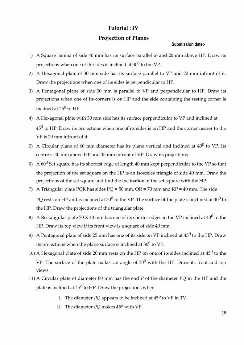
4. Pyramids resting on the HP on its base and one of its base edge is perpendicular to VP
While constructing the top view, see that one side of the given polygon is
perpendicular to xy line 5. Prism resting on the HP on its base and one of its base edge / lateral surface /
rectangular surface is inclined at some angle to VP
While constructing the top view, see that one side of the given polygon is inclined
to the given angle of inclination with respect to VP
22
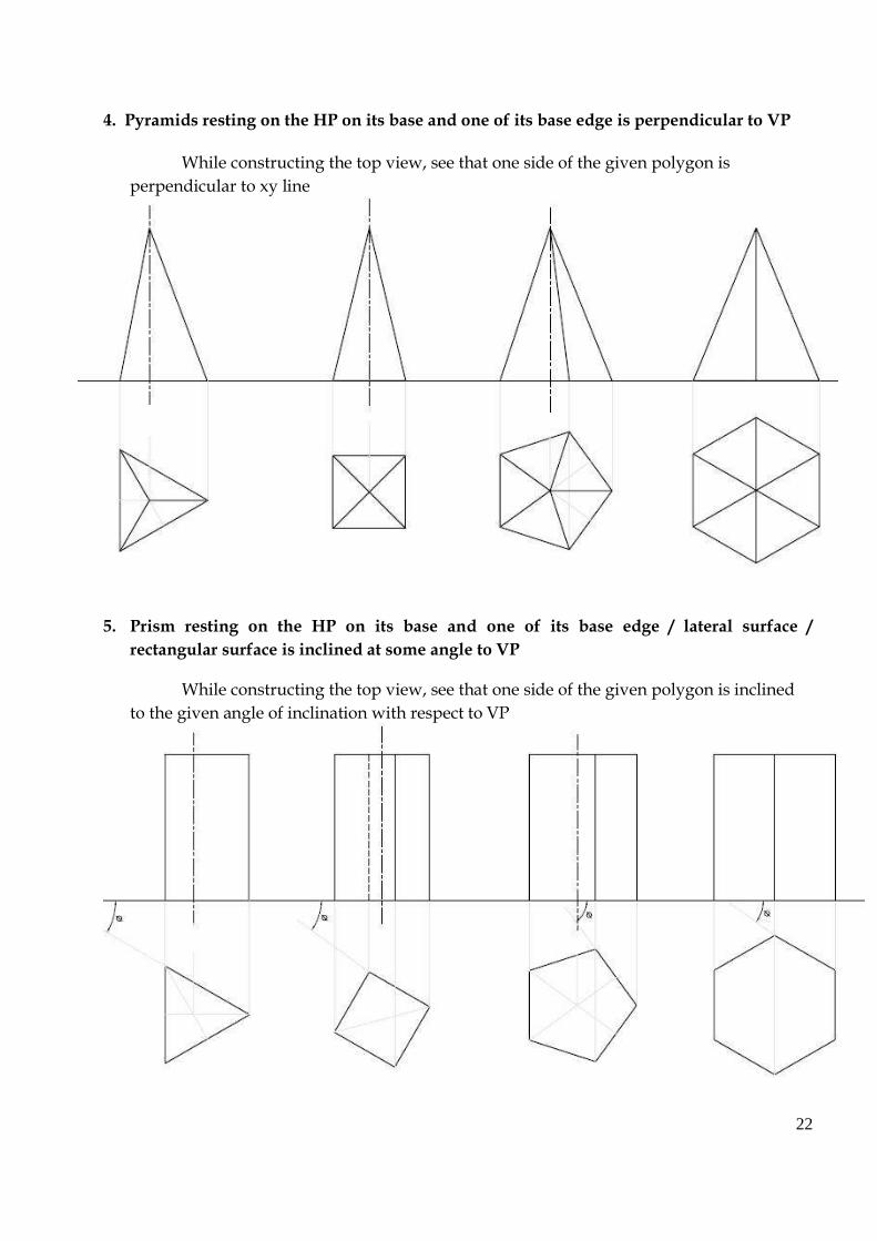
6. Pyramids resting on the HP on its base and one of its base edge is inclined at some
angle to VP
While constructing the top view, see that one side of the given polygon is inclined
to the given angle of inclination with respect to VP II. Solid axis inclined to HP and parallel to VP
How to start with
• When the solid axis is inclined to HP and parallel to VP, make the solid axis perpendicular
to HP and parallel to VP, and the base of the solid should rest on the HP.
• The top view gives the true shape of the polygon. Hence draw the top view first and then
draw its front view. While drawing the front view, see that the base is on the XY line.
• Tilt the front view in the clockwise direction with respect to the rightmost base edge /
corner for the given angle of inclination with respect to HP
• Then project its top view.
(Hints for marking the visible and invisible edges –
1. Blindly connect the outermost boundary points with continuous thick lines.
2. In prisms, two end faces are there. The end face nearer to the observer will be visible. So in
the top view connect all the points of the end face nearer to the observer with continuous
thick line.
23

3. For the base, only one half will be visible. The visible base edges by default will be the
outside boundary of the solid and these edges would have been shown by step 1. Connect
the remaining points by chain dotted lines.
4. Among the N number of lateral edges (N- number of sides of the polygon), two lateral
edges by default will be the outside boundary and these lateral edges would have been
shown by step 1.
5. Now see the front view and see the position of the extreme lateral edges already shown in
the top view.
6. The remaining lateral edges between the observer and the extreme lateral edges (which
forms the outside boundary in top view) will be visible always and hence show these
lateral edges by continuous thick lines
7. The remaining lateral edges between the extreme lateral edges (which forms the outside
boundary in top view) and the reference line will be invisible always and hence show
these lateral edges by chain dotted lines
Resting conditions for the solids having its axis perpendicular to HP and parallel to VP
1. Prisms will rest on the HP either on one of its corners or base side 2. Pyramids will rest on the HP on one of its corners or base side or Triangular surface or
lateral edge 3. Cylinder will rest on HP on one of its base circumferential points 4. Cone will rest on HP on one of its base circumferential points or generator
1. Simple position top view for prisms resting on HP on one of its base edge / Simple position
top view for the pyramids resting on HP on one of its base edge / Simple position top view
for the pyramids having one of its triangular faces on HP
• While constructing the simple position top view of a given polygon, see that one side of
the polygon is perpendicular to VP (XY line) and on the right hand side. Then project its
front view.
• Tilt the front view with respect to the lower most right side edge (which will be the resting
edge on HP) in the clockwise direction to the given angle of inclination with respect to HP.
(Note:- while tilting see that the resting edge is on the XY line)
• Then project its top view.
• Refer the hints for marking the visible and invisible edges.
24
2. Simple position top view for prisms resting on HP on one of its corners / simple position
top view for pyramids resting on HP on one of its corners / Simple position top view for the
pyramids having on of its slant edges on HP
• Construct the top view of the given polygon in such a way that an imaginary line
introduced through one corner of the polygon is perpendicular to VP and on the Right
hand side. Also the two sides containing the corner through which an imaginary line is
introduced is equally inclined to that line. Then project its front view.
• Tilt the front view with respect to the lower most right side corner(which will be the
resting corner on HP) in the clockwise direction to the given angle of inclination with
respect to HP. (Note:- while tilting see that the resting corner is on the XY line)
• Then project its top view.
• Refer the hints for marking the visible and invisible edges.
25

26

27
28

29

30

Tutorial : V
Projections of Solids (Axis perpendicular to one Plane) Submission date:-
1) Draw the projections of the Cube of side 40 mm resting on its base on the HP and one of its vertical
faces inclined at 350 to the VP 2) A Tetrahedron with a 60 mm edge is resting on HP on one of its face in such a way that one of its face
edges is inclined at 450 to the VP. Draw is projections. 3) A Pentagonal prism of base side 35 mm and axis length 60 mm rests on the HP with it is base in such a
way that one of its base edge is inclined at 300 to the VP. Draw its projections.
4) A Hexagonal pyramid of base side 30 mm and axis length 60 mm rests on the HP on its base. Draw its
projections when one of the base edge is parallel to VP and the solid axis is perpendicular to HP. 5) A Pentagonal pyramid of base side 30 mm and axis length 55 mm rests on the HP on its base, in such
a way that one of its base edges is inclined at 300 to VP and the solid axis is perpendicular to HP. Draw
its projections 6) A Cube of side 40 mm is resting on the HP on one of its edges. Draw its projections when one of its
faces containing the resting edge is inclined at 300 to the HP, and the solid axis is perpendicular to VP. 7) A Pentagonal pyramid of base side 30 mm and axis length 60 mm rests on the HP on one of its base
corner, in such a way that one of the base edges containing the resting corner makes 400 to the HP.
Draw its projections when the axis is perpendicular to the VP and the base is touching the VP. 8) A right Circular cone of base diameter 30mm and axis length 60 mm is resting on the HP on one of its
base circumferential point and has its axis perpendicular to VP. Draw its projections when its apex is
nearer to VP. 9) A Hexagonal prism of base side 25 mm and axis length 55 mm lies on the ground on one of its
rectangular faces with its axis perpendicular to VP. Draw its projections when one of its end faces is 15
mm infront of VP. 10) A Pentagonal prism of base side 25 mm and axis length 55 mm lies on the HP on one of its longer /
lateral edges with its axis parallel to both HP and VP. Draw its projections when one of its rectangular
faces containing the resting edge is inclined at 300 to the HP.
11) A Hexagonal pyramid of base side 30 mm and axis length 60 mm lies on the HP on one of its corners of
the base with its axis parallel to both HP and VP. One of the base edges containing the resting corner is
inclined at an angle of 30o to HP. Draw its plan and elevation.
31

Tutorial : VI
Projections of Solids (Axis Inclined to one Plane) Submission date :-
1) Draw the projections of a Pentagonal prism of 25 mm side and axis length 50 mm resting on
the HP on one of its corner in such a way that the two base edges passing through it makes
equal inclinations with HP. Draw its projections when the solid axis is inclined at 300 to the
ground and parallel to VP. 2) A Hexagonal prism of base side 30 mm and axis length 40 mm is resting on the HP on one of
its base edge. Draw its projections when the base containing the resting edge is inclined at 600
to the HP and the solid axis is parallel to VP. 3) Draw the projections of a Cube of side 40 mm when it rests on the ground on one of its corners
with the solid diagonal vertical.
4) A Cylinder of base diameter 50 mm and axis length 60 mm is resting on the HP on a base
circumferential point so that its axis is inclined at 450 to the HP and parallel to the VP. Draw
its plan and elevation. 5) A Cone of base diameter 50 mm and altitude 70 mm rests on the HP on a base
circumferential point with its axis is inclined at 300 to the HP and parallel to the VP. Draw its
front and top views. 6) A Pentagonal pyramid of base edge 30 mm and axis length 60 mm rests on one of its base
edges on the HP with its axis inclined at 300 to the HP and parallel to the VP. Draw its top and
front views. 7) A Hexagonal pyramid of base side 30 mm and axis length 60 mm rests on the HP on one of its
triangular faces with its axis parallel to VP. Draw its projections. 8) A Pentagonal pyramid of base side 30 mm and axis length 55 mm rests on the ground on one
of its lateral edges such that the triangular faces containing the resting edge is equally inclined
to HP. Draw its projections when the solid axis is parallel to VP. 9) A Hexagonal pyramid of base side 30 mm and altitude 75 mm rests on the HP on one of its
base edges such that the triangular face containing the resting edge is perpendicular to both
HP and the VP. Draw its projections.
10) A Hexagonal prism of base side 25 mm and axis length 50 mm is lying on the HP on one of its
rectangular faces with its axis inclined at 450 to the VP. Draw its projections.
32

11) A Square pyramid of base side 30 mm and axis length 50 mm rests on the HP on one of its
base corners with a base side containing the resting corner makes an angle of 350 with the HP.
Draw its projection when the solid axis is inclined at 300 to the VP and the vertex is away from
the VP. 12) A Tetrahedron of edges 50 mm rest on one of its edges on the VP. One of the faces containing
the resting edge is inclined at 300 to the VP. Draw its projections of the tetrahedron when the
resting edge is normal to the HP. 13) A Cylinder of base diameter 50 mm and axis length 60 mm rests on the HP on one of its
generators. Draw its projections when the cylinder axis is inclined at 300 to the VP and parallel
to HP. 14) A Cone of base diameter 50 mm and axis length 60 mm has one of its generators on VP with
the solid axis parallel to and 40 mm above the HP. Draw its projections.
15) A Pentagonal pyramid of base side 25 mm and 60 mm height is suspended from a string
attached to one corner of the base of the pyramid. The string is held, such that the apex of the
pyramid is just touching HP. The axis of the pyramid is parallel to VP. Draw the projections of
the pyramid.
Additional Problems
1) Draw the projections of a Hexagonal prism of 25 mm side and axis length 50 mm resting
on the HP on one of its corner in such a way that the two base edges passing through it
makes equal inclinations with HP. Draw its projections when the solid axis is inclined at
300 to the ground and parallel to VP.
2) A Pentagonal prism of base side 30 mm and axis length 40 mm is resting on the HP on one
of its base edge. Draw its projections when the base containing the resting edge is inclined
at 600 to the HP and the solid axis is parallel to VP.
3) A Pentagonal pyramid of base edge 30 mm and axis length 60 mm rests on one of its base
corners on the HP in such a way that the two base edges containing the resting corner is
equally inclined to HP. Draw its projections with its solid axis inclined at 300 to the HP and
parallel to the VP. Draw its top and front views.
4) A Hexagonal pyramid of base side 30 mm and axis length 60 mm rests on the HP on one of
its slant edges in such a way that the triangular face containing the resting edge is equally
inclined to HP and the solid axis parallel to VP. Draw its projections. 33
5) A Pentagonal pyramid of base side 30 mm and axis length 55 mm rests on the ground on
one of its lateral surface with its solid axis parallel to VP. Draw its projections. 6) A Pentagonal pyramid of base side 30 mm and altitude 75 mm rests on the HP on one of
its base edges such that the triangular face containing the resting edge is perpendicular to
both HP and the VP. Draw its projections.
7) A Square pyramid of base side 40 mm and axis length 60 mm rests on the HP on one of its
slant edges in such a way that the triangular face containing the resting edge is equally
inclined to HP and the solid axis parallel to VP. Draw its projections.
8) A Square pyramid of base side 40 mm and axis length 55 mm rests on the ground on one
of its triangular surface with its solid axis parallel to VP. Draw its projections. 9) A Cone of base diameter 50 mm and axis length 60 mm has one of its generators on HP
with the solid axis parallel to VP. Draw its projections.
10) A Hexagonal pyramid of base side 30 mm and axis length 60 mm has one of its slant edges
on VP in such a way that the triangular face containing the resting edge is equally inclined
to VP and the solid axis parallel to HP. Draw its projections. 11) A Hexagonal pyramid of base side 30 mm and axis length 60 mm rests on the VP on one of
its triangular faces with its axis parallel to HP. Draw its projections.
12) A Pentagonal pyramid of base side 30 mm and axis length 55 mm rests on the VP on one of
its lateral surface with its solid axis parallel to HP. Draw its projections.
13) A Hexagonal pyramid of base side 30 mm and axis length 60 mm has one of its slant edges
on VP in such a way that the triangular face containing the resting edge is equally inclined
to VP and the solid axis parallel to HP. Draw its projections. 14) A Pentagonal pyramid of base side 30 mm and altitude 75 mm rests on the VP on one of its
base edges such that the triangular face containing the resting edge is perpendicular to
both HP and the VP. Draw its projections.
15) A Square pyramid of base side 40 mm and axis length 60 mm rests on the VP on one of its
slant edges in such a way that the triangular face containing the resting edge is equally
inclined to VP and the solid axis parallel to HP. Draw its projections.
16) A Square pyramid of base side 40 mm and axis length 55 mm rests on the VP on one of its
triangular surface with its solid axis parallel to HP. Draw its projections.
34
Tutorial: VII
Sections of Solids Submission date:-
1) A Cube of side 40 mm rests with one of its square faces on HP such that one of its vertical
square faces is inclined at 300 to VP. A section plane, parallel to VP and perpendicular to
HP passes through the solid at a distance of 10 mm away from its vertical axis and infront
of it. Draw its top view, sectional front view. 2) A Hexagonal pyramid of base side 30 mm and axis length 60 mm rests on the HP on its
base such that one of its base edges is parallel to VP and the solid axis is perpendicular to
VP. A cutting plane parallel to VP and perpendicular to HP cuts the solid at a distance of
15 mm away from the axis. Draw its top view, sectional front view. 3) A Pentagonal prism of base side 25 mm and axis length 55 mm rests on the HP on its base
such that one of its base edges is perpendicular to VP and the solid axis is perpendicular to
HP. A section plane parallel to the base and perpendicular to VP cuts the solid axis at a
distance of 15 mm away from the top face. Draw its front view and sectional top view. 4) A Pentagonal pyramid of base side 30 mm and axis length 60 mm rests on the HP on its
base in such a way that one of its base edges is parallel to VP and the solid axis
perpendicular to HP. A section plane parallel to the ground and perpendicular to VP cuts
the solid axis at a distance of 20 mm away from the vertex. Draw its front view and
sectional top view. 5) A Pentagonal prism of base side 40mm and axis length 75mm rests on the HP on one of its
ends with a rectangular face parallel to the VP. It is cut by a plane perpendicular to the
VP, inclined at 300 to the HP and meeting the solid axis at 25 mm from the top face. Draw
the front, sectional top view and true shape of the section. 6) A Cone of base diameter 40 mm and altitude 50 mm rests on its base on HP. It is cut by a
section plane perpendicular to VP and inclined at 80o to HP, passing through the apex.
Draw the front view, sectional top view and true shape of the section 7) A Cone of base diameter 50mm and altitude 60mm rests on its base on the HP. It is cut by a
plane perpendicular to the VP and parallel to one of the extreme generators, 10 mm away
from it. Draw the sectional top view and true shape of the section.
35

8) A cone of base diameter 40 mm and height 50 mm rests on its base on the HP. It is cut by
a plane perpendicular to the VP and inclined at 40 0 to the HP. The cutting plane meets the
axis at 20 mm from the vertex. Draw the sectional top view and the true shape of the
section. 9) A Hexagonal pyramid of base side 25 mm and axis 55 mm rests on HP on its base with
two edges parallel to VP. It is cut by a vertical plane inclined at 30o to VP and cutting the
pyramid at a distance of 6 mm away from the plan of the axis. Draw the top view, sectional
front view and true shape of the section. 10) A Cylinder of diameter 50mm and height 65 mm rests on its base on the HP. It is cut by a
plane Perpendicular to the VP and inclined at 600 to the HP. The cutting plane meets the
axis at a distance of 40 mm above the base. Draw the sectional top view and the true shape
of the section. 11) A Cube of side 50 mm is placed and cut by a plane in such a way that the true shape of the
section is regular hexagon. Draw the front and top views of the cube and find the
inclination of the cutting plane with the HP 12) A Tetrahedron of edge 60 mm rests on the HP on one of its face such that one of the edges
of the resting face is perpendicular to VP. It is cut by a plane perpendicular to VP and
inclined to the HP in such a way that the true shape of the section is an isosceles triangle of
base 40mm and altitude 30mm. Find the inclination of the cutting plane with the HP. Also
draw the front view, sectional top view and true shape of the section
13) A Sphere of diameter 80 mm is cut by a VP inclined at 40o to VP. The Cutting plane is
located at a minimum distance of 20 mm from the center of the sphere. Draw its top view,
sectional front view and true shape of the section.
36
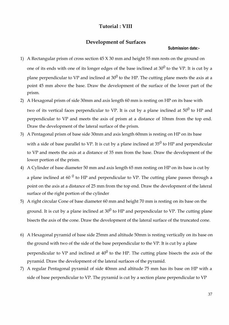
Tutorial : VIII
Development of Surfaces Submission date:-
1) A Rectangular prism of cross section 45 X 30 mm and height 55 mm rests on the ground on
one of its ends with one of its longer edges of the base inclined at 300 to the VP. It is cut by a
plane perpendicular to VP and inclined at 300 to the HP. The cutting plane meets the axis at a
point 45 mm above the base. Draw the development of the surface of the lower part of the
prism. 2) A Hexagonal prism of side 30mm and axis length 60 mm is resting on HP on its base with
two of its vertical faces perpendicular to VP. It is cut by a plane inclined at 500 to HP and
perpendicular to VP and meets the axis of prism at a distance of 10mm from the top end.
Draw the development of the lateral surface of the prism. 3) A Pentagonal prism of base side 30mm and axis length 60mm is resting on HP on its base
with a side of base parallel to VP. It is cut by a plane inclined at 350 to HP and perpendicular
to VP and meets the axis at a distance of 35 mm from the base. Draw the development of the
lower portion of the prism. 4) A Cylinder of base diameter 50 mm and axis length 65 mm resting on HP on its base is cut by
a plane inclined at 60 0 to HP and perpendicular to VP. The cutting plane passes through a
point on the axis at a distance of 25 mm from the top end. Draw the development of the lateral
surface of the right portion of the cylinder 5) A right circular Cone of base diameter 60 mm and height 70 mm is resting on its base on the
ground. It is cut by a plane inclined at 300 to HP and perpendicular to VP. The cutting plane
bisects the axis of the cone. Draw the development of the lateral surface of the truncated cone.
6) A Hexagonal pyramid of base side 25mm and altitude 50mm is resting vertically on its base on
the ground with two of the side of the base perpendicular to the VP. It is cut by a plane
perpendicular to VP and inclined at 400 to the HP. The cutting plane bisects the axis of the
pyramid. Draw the development of the lateral surfaces of the pyramid. 7) A regular Pentagonal pyramid of side 40mm and altitude 75 mm has its base on HP with a
side of base perpendicular to VP. The pyramid is cut by a section plane perpendicular to VP
37

and inclined at 300 to the HP. The cutting plane meets the axis of the pyramid at a point 30
mm below the vertex. Obtain the development of the remaining part of the pyramid. 8) A Square pyramid of base side 35 mm and axis 60 mm rests on its base on the HP with one of
the sides of the base inclined at 300 to the VP. A string is wound round the surfaces of the
pyramid starting from left extreme point on the base and ending at the same point. Find the
shortest length of the string required. Also trace the path of the string in the front and top
views. 9) A Cone of base diameter 60 mm and height 70 mm is resting on its base on the ground. It is
cut by a plane perpendicular to the VP and parallel to the HP at a distance of 20 mm from the
vertex. It is also cut by a plane inclined at 400 to the base and meeting the axis at a point 20
mm above the base. Draw the development of the lateral surface of the cut cone. 10) A Pentagonal prism of base side 25 mm and height 60 mm stands on one of its ends on the HP
with a rectangular face parallel to the VP. A hole of diameter 30 mm is drilled centrally
through the prism in such a way that the axis of the hole bisects the axis of the prism at right
angles. The axis of the hole is perpendicular to the VP. Draw the development of the lateral
surfaces of the prism. 11) A Cone of base diameter 60 mm and height 70 mm rests vertically on its base on the ground.
A string is wound round the curved surface of the cone starting from the left extreme point on
the base and ending at the same point. Find the shortest length of the string required. Also,
trace the path of the string in the front and the top views. 12) A Funnel tapers from a circular opening of diameter 70 mm to a circular opening of diameter
20 mm over an axial length of 50 mm and extends axially to a further distance of 40 mm. There
is a cylindrical portion of height 15 mm above the tapering portion. Develop the funnel.
38

Tutorial : IX
Isometric Projection Submission date:-
1. Draw the isometric view of (a) Hexagonal prism (b) Pentagonal prism of base side 25 mm and
axis height 50 mm when it rests on one of its ends on the HP with one of its base sides parallel
to VP. 2. Draw the isometric view of (a) Cylinder (b) Cone of base diameter 60 mm and axis length
70mm when it’s resting on its base on HP. 3. Draw the isometric projection of (a) Hexagonal Pyramid (b) Pentagonal pyramid of base side
30 mm and axis length 60mm when it rests on its base with one of its base side perpendicular
to VP. 4. A Hexagonal prism of base edge 25 mm and height 50 mm rests on the HP on its base with
two of its rectangular face perpendicular to the VP. It is cut by a plane inclined at 300 to HP
and perpendicular to VP at a distance of 40 mm from its base. Draw the isometric view of the
truncated prism. 5. A Pentagonal prism of base side 35 mm and axis length 70 mm rests on the ground with its
two adjacent rectangular faces equally inclined to VP and nearer to the observer. A section
plane perpendicular to the VP and inclined at 450 to the HP passes through a point on the axis
50 mm above the base of the prism. Draw the isometric projection of the truncated prism.
6. A Pentagonal pyramid of base side 30mm and axis length 65mm is resting on HP on its base
with a side of base perpendicular to VP. It is cut by a plane inclined at 300 to HP and
perpendicular to VP and passes through a point at a distance of 30 mm from the apex. Draw
the isometric view of the remaining portion of the pyramid. 7. Draw the isometric view of a frustum of a Hexagonal pyramid when it is resting on its base on
the HP with two sides of the base parallel to the VP. The side of base is 30 mm and top face is
10 mm. The height of the frustum is 55 mm.
8. A Cylinder of base diameter 60 mm and height 70 mm rests with its base on HP. A section
plane perpendicular to VP and inclined at 450 to HP passes through the axis at a distance of 50
mm above its base. Draw the isometric view of the truncated cylinder showing the cut surface.
39

9. A Cone of base diameter 60 mm and height 65 mm rests with its base on HP. A cutting pane
perpendicular to VP and inclined at 300 to HP cuts the cone such that it passes through a point
on the axis at a distance of 30 mm above the base of the cone. Draw the isometric view of the
truncated cone showing the cut surface. 10. A combination of the solids is formed as follows: A frustum of a Cone 25 mm top diameter, 50
mm bottom diameter and 50 mm height is placed vertically on a Cylindrical block of 75 mm
diameter and 25 mm thick such that both the solids have the common axis. Draw the isometric
view of the combinations of the solid. 11. Three square rods of 30mm x 30mm cross section and lengths 100mm, 100mm and 60mm are
so nailed together that they form the letter ‘H’. Draw the isometric view of the letter ‘H’ 12. A dust bin is in the form of a frustum of a hollow Square pyramid with the base dimensions of
20 mm sides and the top open surface of 45 mm sides. Draw the isometric view of the hollow
dust bin, if its height is 50 mm and the wall thickness is negligible.
40

Tutorial : X
Perspective Projection Submission date:-
1) A Square prism of base 25 X 25 mm and height 40 mm rests on the GP with the edges of
the base making 450 with the PP. The vertical edge nearer to the PP is 25 mm to the right of
the station point and 25 mm behind the PP. The station point is 55mm above GP and 70
mm in front of PP. Draw the perspective view of the solid. 2) A Rectangular prism 40X30X15 mm rests on the ground on one of its ends with one of the
longest edges touching the PP and the shortest edges receding to the left at an angle of 400
to the PP. The nearest vertical edge is 15 mm to the left of the station point, which is at a
distance of 55mm in front of the PP and 30 mm above the ground. Draw the perspective
view of the solid. 3) A Hexagonal prism of base side 25 mm and height 50 mm is resting with its base on the
GP such that one of its rectangular faces is inclined at 300 to the PP and the vertical edge
nearer to PP is 15 mm behind it. The station point is 45 mm in front of the PP, 70 mm
above the GP and lies in a central plane, which is 15 mm to the left of the vertical edge
nearer to the PP. Draw the perspective view of the solid. 4) A Square pyramid of base side 30 mm and altitude 40 mm rests on its base on the ground
such that one of its base sides is parallel to the picture plane and 10 mm in front of it. The
station point is 50 mm in front of the picture plane, 25 mm to the left of the axis of the
pyramid and 55 mm above the ground. Draw the perspective view of the pyramid. 5) A Hexagonal pyramid of base side 25 mm and axis length 50 mm is resting on the GP on
its base with a side of base inclined at 300 to PP. The nearest corner to the PP is 20mm
behind it. The station point is 60mm above the GP and 80 mm in front of PP and lies in a
central plane, which is 50 mm to the left of the axis of the pyramid. 6) A frustum of a Square pyramid of base edge 26 mm, top edge 20 mm and height 35 mm
rests on its base on the ground with base edges equally inclined to the PP. The axis of the
frustum is 30 mm to the right of the eye. The eye is 45 mm infront of the PP and 50 mm
above the ground. The nearest base corner is 10 mm behind the PP. Draw the perspective
projection of the frustum.
41

7) Draw the perspective view of a Pentagonal prism of base side 20 mm and height 40 mm
when it rests on its base on the ground plane with one of the rectangular faces parallel to
and 20 mm behind the picture plane. The station point is 45 mm infront of the PP and 60
mm above the GP. The observer is 20 mm to the left of the axis. Use top view and the end
view to draw the perspective by visual ray method.
8) A Hexagonal prism of base side 25 mm and axis length 50 mm rests on the ground on one
of its rectangular faces with its axis inclined at 300 to the picture plane. A corner of the base
is touching the PP. The station point is 60 mm infront of the PP and lies in a central plane
that bisects the axis. The station point is 40 mm above the ground plane. Draw the
perspective view of the prism.
42

Conic sections
43
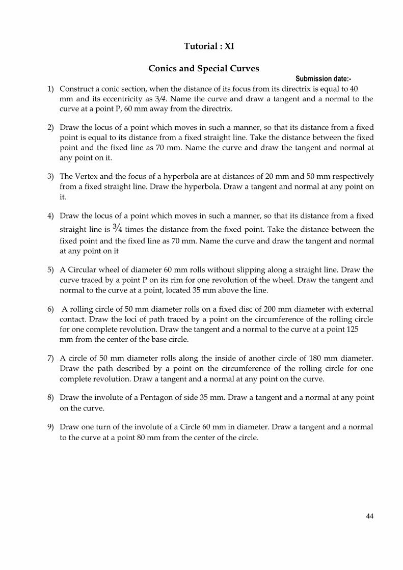
Tutorial : XI
Conics and Special Curves Submission date:-
1) Construct a conic section, when the distance of its focus from its directrix is equal to 40 mm and its eccentricity as 3/4. Name the curve and draw a tangent and a normal to the
curve at a point P, 60 mm away from the directrix. 2) Draw the locus of a point which moves in such a manner, so that its distance from a fixed
point is equal to its distance from a fixed straight line. Take the distance between the fixed
point and the fixed line as 70 mm. Name the curve and draw the tangent and normal at
any point on it. 3) The Vertex and the focus of a hyperbola are at distances of 20 mm and 50 mm respectively
from a fixed straight line. Draw the hyperbola. Draw a tangent and normal at any point on
it. 4) Draw the locus of a point which moves in such a manner, so that its distance from a fixed
straight line is ¾ times the distance from the fixed point. Take the distance between the
fixed point and the fixed line as 70 mm. Name the curve and draw the tangent and normal
at any point on it 5) A Circular wheel of diameter 60 mm rolls without slipping along a straight line. Draw the
curve traced by a point P on its rim for one revolution of the wheel. Draw the tangent and
normal to the curve at a point, located 35 mm above the line. 6) A rolling circle of 50 mm diameter rolls on a fixed disc of 200 mm diameter with external
contact. Draw the loci of path traced by a point on the circumference of the rolling circle
for one complete revolution. Draw the tangent and a normal to the curve at a point 125 mm from the center of the base circle.
7) A circle of 50 mm diameter rolls along the inside of another circle of 180 mm diameter.
Draw the path described by a point on the circumference of the rolling circle for one
complete revolution. Draw a tangent and a normal at any point on the curve. 8) Draw the involute of a Pentagon of side 35 mm. Draw a tangent and a normal at any point
on the curve. 9) Draw one turn of the involute of a Circle 60 mm in diameter. Draw a tangent and a normal
to the curve at a point 80 mm from the center of the circle. 44

Orthographic Projections
45
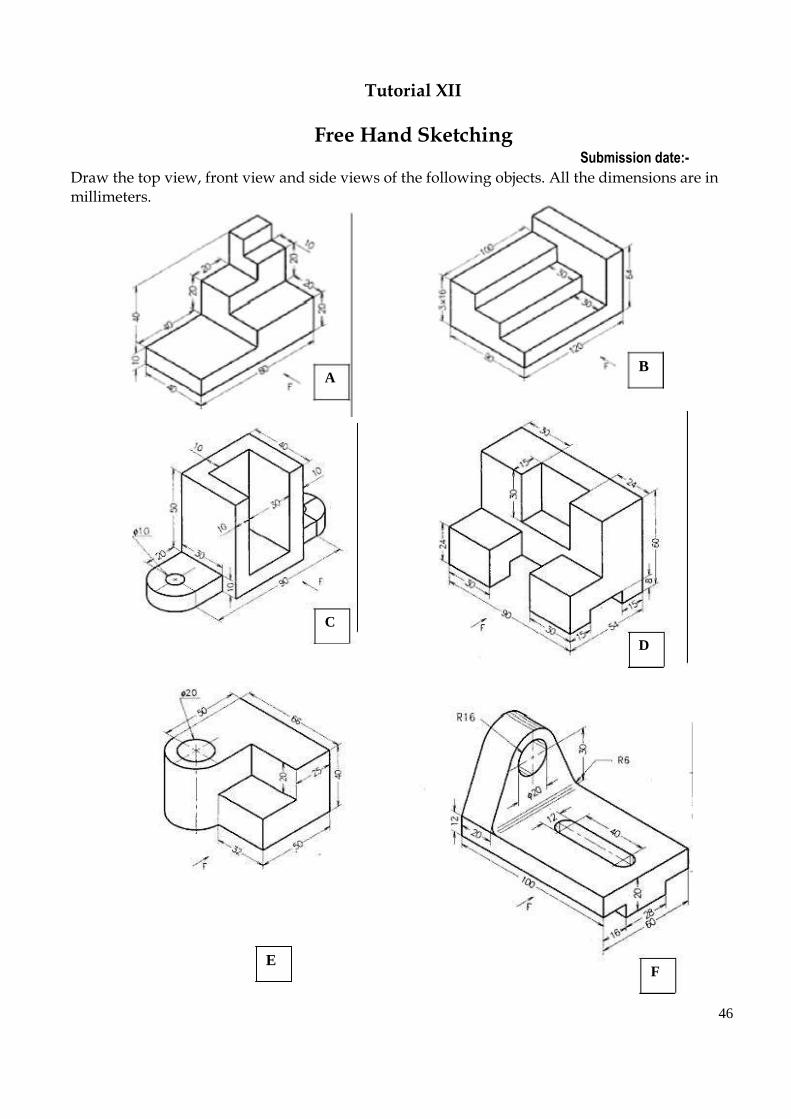
Tutorial XII
Free Hand Sketching Submission date:-
Draw the top view, front view and side views of the following objects. All the dimensions are in millimeters.
A C
B
D
E
F
46

G H
I J
L
K

47

University Question Paper
B.E./ B.Tech. Degree Examinations, November / December 2010 Regulations 2008
First Semester Common to all branches
GE 2111 Engineering Graphics
Time: Three Hours Maximum: 100 marks Answer ALL questions
(5 X 20 = 100 marks)
1. (a) A circle of 50 mm diameter rolls along a line. A point on the circumference of
the circle is in contact with the line in the beginning and after one
complete revolution. Draw the cycloidal path of the point. Draw a tangent and normal at any point on the curve. (20) (OR)
1. (b) Make free hand sketches of the front, top and right side views of the object
shown below.
(20)
2. (a) A line AB, 90 mm long, is inclined at 450 to the HP and its top view makes an
angle of 600 with the VP. The end A is in HP and 12 mm in front of the VP. Draw its front view and find its true inclination with the VP. (20)
(OR) 2. (b) A rectangular plate 70 X 40 mm has one of its shorter edges in the VP inclined
at 400 to the HP. Draw its top view, if its front view is a square of side 40 mm. (20)
3. (a) A pentagonal prism of edge of base 30 mm and axis 70 mm long rests with
one of its rectangular faces on HP and the ends inclined at 300 to VP. Draw
its projections. (20)
(OR)
3. (b) Draw the projections of a hexagonal pyramid with side of the base 30 mm and axis 70 mm long, when it is resting with one of the base sides on HP such
that the triangular face containing that side is perpendicular to HP and axis is parallel to VP. (20)
48

4. (a) A cone, diameter of base 60 mm and height 60 mm, is resting on HP on its
base. It is cut by a plane inclined to HP at 300 and perpendicular to VP. The
cutting plane passes through one of the extreme generators at a height of 10 mm above the base. Draw the front view, sectional top view and the true shape of the section. (20)
(OR)
4. (b) A cone of base 60 mm and height 80 mm is resting with its base on HP. An
insect starts from a point on the circumference of the base, goes round the
solid and reaches the starting point in the shortest path. Find the distance
traveled by the insect and also the projections of the path followed by it. (20)
5. (a) Draw the isometric projection of a frustum of a hexagonal pyramid when it
is resting on its base on the HP with two sides of the base parallel to the
VP. The side of base is 20 mm and the top 8 mm. The height of the frustum
is 55 mm. (20)
(OR)
5. (b) A rectangular prism of base 30 x 15 mm and height 40 rests on the ground on one its base ends with one of the lateral edges touching the PP and the
shortest edge of the base inclined at an angle of 400 to the PP. The nearest
vertical edge is 15 mm to the left of the station point which is at a distance
of 55 mm in front of the PP and 30 mm above the ground. Draw the
perspective view of the prism. (20)
49
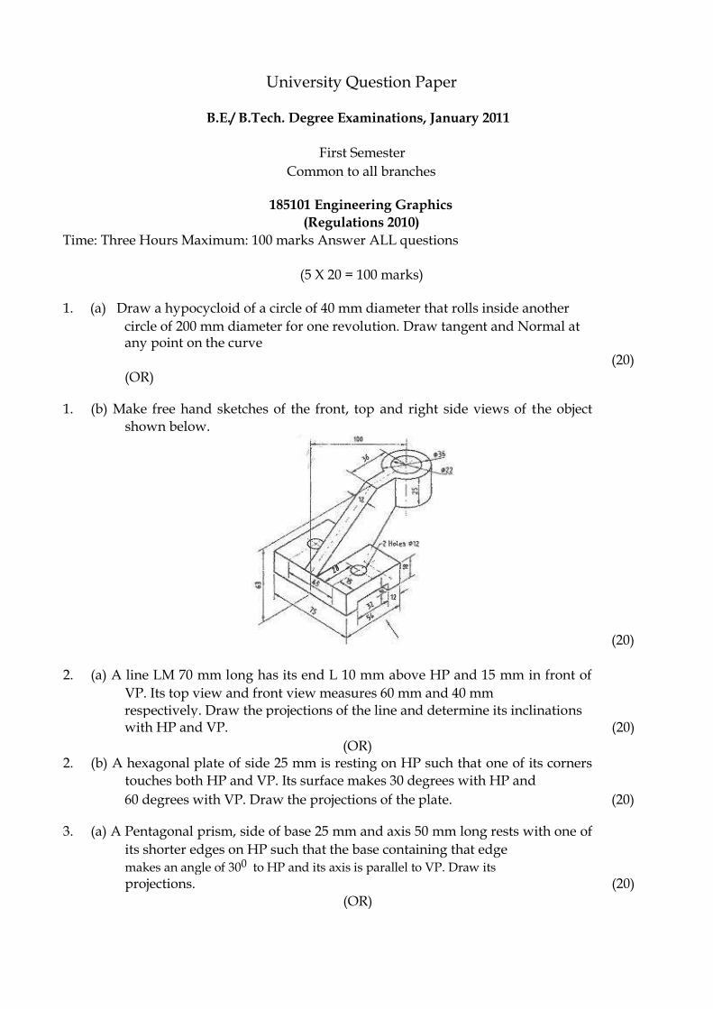
University Question Paper
B.E./ B.Tech. Degree Examinations, January 2011
First Semester Common to all branches
185101 Engineering Graphics
(Regulations 2010) Time: Three Hours Maximum: 100 marks Answer ALL questions
(5 X 20 = 100 marks)
1. (a) Draw a hypocycloid of a circle of 40 mm diameter that rolls inside another circle of 200 mm diameter for one revolution. Draw tangent and Normal at any point on the curve
(20) (OR)
1. (b) Make free hand sketches of the front, top and right side views of the object
shown below.
(20)
2. (a) A line LM 70 mm long has its end L 10 mm above HP and 15 mm in front of
VP. Its top view and front view measures 60 mm and 40 mm respectively. Draw the projections of the line and determine its inclinations
with HP and VP. (20)
(OR)
2. (b) A hexagonal plate of side 25 mm is resting on HP such that one of its corners
touches both HP and VP. Its surface makes 30 degrees with HP and 60 degrees with VP. Draw the projections of the plate. (20)
3. (a) A Pentagonal prism, side of base 25 mm and axis 50 mm long rests with one of
its shorter edges on HP such that the base containing that edge
makes an angle of 300 to HP and its axis is parallel to VP. Draw its
projections. (20)
(OR)

3. (b) A Hexagonal pyramid of 26 mm side of base and 70 mm height rests on HP (20) 50

on one of its base edges such that the triangular face containing the resting
edge is perpendicular to both HP and VP. Draw its projections. 4. (a) Square prism side of base 30 mm and axis 60 mm long rests with its base on
HP and one of its rectangular faces is inclined at 300 to VP. A sectional plane
perpendicular to VP and inclined at 600 to HP cuts the axis of the prism at a point 20 mm from its top end. Draw the sectional top view and the true shape of the section. (20)
(OR)
4. (b) A monument is in the form of frustum of a square pyramid of base 1.2 m side,
top 0.5 m side and height 1.0 m. An electrical connection is to be made
along the surface of this monument between one of the base and
diagonally opposite corner on the top. Find the shortest length of the wire
required and show the position of the wire in the top and front views. (20)
5. (a) A hexagonal prism side of base 25 mm and height 50 mm rests on HP and one
of the edges of its base is parallel to VP. A section plane perpendicular
to VP and inclined at 500 to HP bisects the axis of the prism. Draw the
isometric projection of the truncated prism. (20)
(OR)
5. (b) A square prism of base side 30 mm and height 50 mm rests with its base on the
ground and one of the rectangular faces inclined at 300 to the PP. The
nearest vertical edge touches the PP. The station point is 60 mm above the GP, 45 mm in front of the PP and opposite to the nearest vertical edge that touches the PP. Draw the perspective view of the square prism. (20)
51
University Question Paper
B.E./ B.Tech. Degree Examinations, January 2011 Regulations 2010
First Semester Common to all branches
185101 Engineering Graphics
Time: Three Hours Maximum: 100 marks Answer ALL questions
(5 X 20 = 100 marks)
1. (a) A circular wheel of 50 mm diameter rolls without slipping along a straight
line. Draw the curve traced by a point ‘P’ on its rim for one revolution of
the wheel. Draw tangent and normal at any point M on the curve. (20)
(OR)
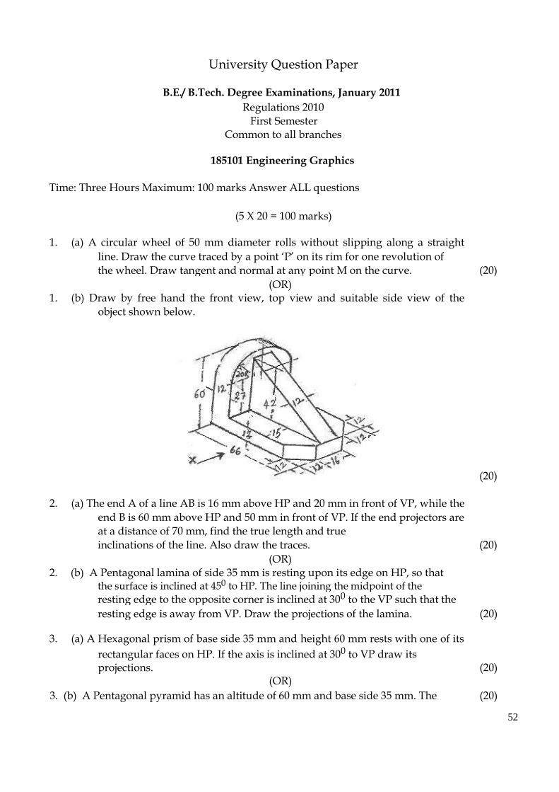
1. (b) Draw by free hand the front view, top view and suitable side view of the
object shown below.
(20)
2. (a) The end A of a line AB is 16 mm above HP and 20 mm in front of VP, while the
end B is 60 mm above HP and 50 mm in front of VP. If the end projectors are
at a distance of 70 mm, find the true length and true
inclinations of the line. Also draw the traces. (20)
(OR)
2. (b) A Pentagonal lamina of side 35 mm is resting upon its edge on HP, so that the surface is inclined at 450 to HP. The line joining the midpoint of the
resting edge to the opposite corner is inclined at 300 to the VP such that the
resting edge is away from VP. Draw the projections of the lamina. (20) 3. (a) A Hexagonal prism of base side 35 mm and height 60 mm rests with one of its
rectangular faces on HP. If the axis is inclined at 300 to VP draw its projections. (20)
(OR)
3. (b) A Pentagonal pyramid has an altitude of 60 mm and base side 35 mm. The (20) 52

pyramid rests with one of its sides of the base on HP such that the triangular
face containing that side is perpendicular to both HP and VP. 4. (a) A Pentagonal pyramid of base side 40 mm and height 80 mm rests on the base
such that one base edge is perpendicular to VP. It is cut by a section plane
inclined at 450 to HP and passing through the mid point of the axis
removing the apex. Draw the front view, sectional top view and true shape of the section.
(20) (OR)
4. (b) A Cone of base diameter 80 mm and axis height 80 mm rests on the HP on its
base. A square hole of side 40 mm is cut horizontally through the cone
such that the axis of the hole and the square intersect at a height of 16 mm
from the base. If the sides of the hole are equally inclined to the HP, draw
the development of the lateral surface of the cone. (20)
5. (a) Draw the isometric view of the frustum of a hexagonal pyramid when it is resting on its base on the HP with two sides of the base parallel to the VP.
The pyramid has base side of 30 mm and top side of 10 mm. the height of
the frustum is 60 mm. (20)
(OR)
5. (b) Draw the perspective view of a Pentagonal prism of base side 30 mm and
height 50 mm when it rests on its base on the ground plane with one of its
rectangular faces parallel to and 20 mm behind the picture plane. The
station point is 45 mm in front of the picture plane and 60 mm above the GP.
The observer is 20 mm to the left of the axis. Using the top view and
the end view draw the perspective view of the prism using visual ray
method (20)
53

University Question Paper
B.E./ B.Tech. Degree Examinations, January 2012 Regulations 2008
First Semester Common to all branches
GE 2111 Engineering Graphics
Time: Three Hours Maximum: 100 marks Answer ALL questions
(5 X 20 = 100 marks)
1. (a) Draw the involute of a circle of diameter 50 mm when a string is unwound in the clockwise direction. Draw a tangent and normal at
(20)
a point located on the involute.
(OR)
1. (b) Make free hand sketches of the front, top and right side views of the object
shown below.
(20)
2. (a) The front view of a line AB 90 mm long is inclined at 45° to XY line. The front view measures 65 mm long. Point A is located 15 mm
above H.P. and is in V.P. Draw the projections and find its true
(20)
inclinations
(OR)
2. (b) A hexagonal lamina of side 30 mm rests on one of its edges on H.P. This edge is parallel to V.P. The surface of the lamina is inclined 60° to H.P. Draw its projections (20)
3. (a) A hexagonal prism of side of base 25 mm and axis 60 mm long, is freely
suspended from a corner of the base. Draw the projections by
the change of Position method. (20) (OR)
54

3. (b) A cylinder, diameter of base 60 mm and height 70 mm, is having a point of its periphery of base on H.P. with axis of the cylinder
inclined to H.P. at 45° and parallel to V.P. Draw the projections of
the cylinder (20)
4. (a) A cone of base 75 mm diameter and axis 80 mm long is resting on its base on
the H.P. It is cut by a section plane perpendicular to the V.P.
and parallel to and 12 mm away from one of its end generators. Draw its front
view, sectional top view and true shape of the section (20)
(OR)
4. (b) A regular hexagonal pyramid side of base 30 mm and height 60 mm is resting
vertically on its base on H.P. such that two of its sides of the base are
perpendicular to V.P. It is cut by a plane inclined at 40° to H.P. and
perpendicular to V.P. The cutting plane bisects the axis of the pyramid. Obtain the development of the lateral surface of the
(20)
truncated pyramid
5. (a) A cone of diameter of base 60 mm and height 65 mm rests with its base on H.P. A cutting plane perpendicular to V.P. and inclined at
30° to H.P. cuts the cone such that it passes through a point on the
axis at a distance of 30 mm above the base of the cone. Draw the
(20)
isometric projection of the truncated cone showing the cut surface
(OR)
5. (b) A square prism of base 25 x 25 mm and height 40 mm is resting on the GP on
its square base with a right side rectangular face making
60° with Picture Plane. The corner nearest to the PP is 40 mm to the
left of the station point and 20 mm behind the PP. The station point
is 60 mm above the GP and 50 mm in front of the PP. Draw the
perspective view of the prism by using Visual Hay Method (20)
55

University Question Paper
B.E./ B.Tech. Degree Examinations, January 2012
Regulations 2008
First Semester
Common to all branches
GE 2111 Engineering Graphics
Time: Three Hours Maximum: 100 marks
Answer ALL questions
(5 X 20 = 100 marks)
1. (a) Draw the locus of a point P which moves in a plane in such a way that
the ratio of its distances from a fixed point F and a fixed straight line
AB is always 2/3. The distance between the fixed point F and fixed
straight line is 50 mm. Also draw a tangent and normal on a point on
the locus at a horizontal distance of 55 mm from the fixed straight line (20)
(OR)
1. (b) Draw the free hand sketches of the Front View, Top view and Right side view
of the machine component given below in figure.
(20)
2. (a) A line PQ measuring 70 mm is inclined to H.P. at 30° and to V.P. at 45° with the end P 20 mm above H.P. and 15 mm in front of VP,
Draw its projections (20) (OR)
2. (b) A rectangular plate of side 50 x 25 mm is resting on its shorter side
on H.P. and inclined at 30° to V.P. Its surface is inclined at 60° to
H.P. Draw its projections. (20)
3. (a) Draw the projections of a pentagonal prism of 30 mm base edges
and axis 60 mm long when the axis is inclined at 75° to the H.P. and
parallel to the V.P. with an edge of the base on the H.P.. (20) 56

(OR) 3. (b) A right regular hexagonal pyramid, edge of base 25 mm and height 50 mm,
rests on one of its base edges on H.P. with its axis parallel to V.P. Draw the projections of the pyramid when its base makes an
angle of 45° to the H.P. (20)
4. (a) A square pyramid base 40 mm side and axis 65 mm long has its base on H.P.
and all the edges of the base are equally inclined to V.P. It is cut by a section
plane perpendicular to V.P. and inclined at 45° to H.P. and bisecting the axis. Draw its sectional top view, and the
(20)
true shape of the section.
(OR)
4. (b) Draw the development of the lateral surface of the lower portion of a cylinder of diameter 50 mm and axis 70 mm. The solid is cut by a
section plane inclined at 40° to H.P. and perpendicular to V.P. and
passing through the midpoint of the axis. (20)
5. (a) Draw the isometric projection of the object from the views shown in figure
(20) (OR)
5. (b) A rectangular pyramid, base 30 mm x 20 mm and axis 35 mm long, is placed
on the ground plane on its base, with the longer edge of the base parallel to
and 30 mm behind the picture plane. The central plane is 30 mm to the left
of the apex and station point is 50 mm in front of the picture plane and 25 mm above the ground plane. Draw
(20)
the perspective view of the pyramid.
57

University Question Paper
B.E./ B.Tech. Degree Examinations, May / June 2012
Regulations 2008
First Semester
Common to all branches
GE 2111 Engineering Graphics
Time: Three Hours Maximum: 100 marks
Answer ALL questions
(5 X 20 = 100 marks)
1. (a) Draw a hyperbola when the distance of the focus from the directrix is
70 mm and the eccentricity e is l.5. Draw the tangent and normal to
the curve at a point P distance 50 mm from the directrix (20)
(OR)
1. (b) Make a freehand sketch of the following three views, of the block shown
pictorially in figure. (i) Front view (ii) Top view and (iii) Side view from the right. .
(20)
2. (a) The projections of a line AB are perpendicular to xy. The end A is in HP and 50 mm in front of VP and the end B is in VP and 40 mm above HP. Draw its projections, determine its true length and the inclinations with the HP and VP. (20)
(OR) 2. (b) A square lamina PQRS of side 40 mm rests on the ground on its
corner P in such a way that the diagonal PR is inclined at 45° to HP
(20)
and also apparently inclined at 30° to VP. Draw its projections
3. (a) Draw the projections of a cube of edge 45 mm resting on one of its corners on HP, with a solid diagonal perpendicular to HP. (20)
(OR)
3. (b) A square pyramid of base 40 mm and axis 70 mm long has one of its triangular
faces on VP and the edge of base contained by that face perpendicular to HP. Draw its projections (20)
58
4. (a) A vertical cylinder 40 mm diameter is cut by a vertical section plane making 30° to VP in such a way that the true shape of the section is a
rectangle of 25 mm and 60 mm sides. Draw the projections and true
shape of the section. (20)
(OR)
4. (b) A rectangular pyramid 60 mm x 50 mm and height 75 mill is resting on its base
on HP with its longer base edges parallel to VP. It is
sectioned by a plane perpendicular to VP, inclined at 65° to HP and
passing through the mid-point of the axis. Develop the lateral
(20)
surfaces of the cut pyramid
5. (a) A cylinder of diameter of base GO mm and height 70 mm rests with its base in
HP. A section plane perpendicular to VP and inclined at 45° to HP cuts the
cylinder such that it passes through a point on the axis 50 mm above the
base. Draw the isometric projection of the truncated cylinder showing the
cut surface. (20)
(OR)
5. (b) Draw the perspective view of a square prism base side 20 mm height 35 mm
resting on its base on the ground with a rectangular face parallel to the
picture plan. The axis of the prism is 25 mm behind
the picture plane and 25 mm to the right of the eye. The eye is 50 mm
(20)
in front of picture plane and 50 mm above the ground.
59