ge stenoscop 2 advanced service manual-1
TRANSCRIPT

HOME
Medical Systems Medical Systems eAdvanced Service ManualAdvanced Service Manual

GE Medical Systems STENOSCOP 2 – STENOSCOP Plus
REV 3 asm 826 921 P635
i
SUMMARY
CHAPTER 1 – EVOLUTION OF STENOSCOP LINE 1 . 1. . . . . . . . . . . . . . . . . . . . . .
CHAPTER 2 – THEORY 2 . 1. . . . . . . . . . . . . . . . . . . . . . . . . . . . . . . . . . . . . . . . . . . . . .
2–1 STENOSCOP 2 . 1. . . . . . . . . . . . . . . . . . . . . . . . . . . . . . . . . . . . . . . . . . . . . . . . . . . . . . . . . . .
2–2 IMAGER 16 OR 22 2 . 43. . . . . . . . . . . . . . . . . . . . . . . . . . . . . . . . . . . . . . . . . . . . . . . . . . . . . .
2–3 MEMORIES 2 . 71. . . . . . . . . . . . . . . . . . . . . . . . . . . . . . . . . . . . . . . . . . . . . . . . . . . . . . . . . . . .
2–4 MONITOR DISTAR 2 . 109. . . . . . . . . . . . . . . . . . . . . . . . . . . . . . . . . . . . . . . . . . . . . . . . . . . . . .
CHAPTER 3 – ADJUSTMENT – TROUBLESHOOTING – DIAGNOSIS 3 . 1. . . . .
3–1 GENERAL 3 . 1. . . . . . . . . . . . . . . . . . . . . . . . . . . . . . . . . . . . . . . . . . . . . . . . . . . . . . . . . . . . . .
3–2 JOB CARDS SYNOPTIC TABLE . 3 . 1. . . . . . . . . . . . . . . . . . . . . . . . . . . . . . . . . . . . . . . . .
3–2 IMAGEUR ADJUSTMENTS SHEETS 3 . 3. . . . . . . . . . . . . . . . . . . . . . . . . . . . . . . . . . . . . .
3–4 IMAGEUR TROUBLESHOOTING SHEETS 3 . 61. . . . . . . . . . . . . . . . . . . . . . . . . . . . . . . .
3–5 MDA MEMORY DIAGNOSIS SHEETS 3 . 85. . . . . . . . . . . . . . . . . . . . . . . . . . . . . . . . . . . . .

GE Medical Systems STENOSCOP 2 – STENOSCOP Plus
REV 3 asm 826 921 P635
ii
Blank page

GE Medical Systems STENOSCOP 2 – STENOSCOP Plus
REV 3 asm 826 921 P635
iii
REVISION HISTORY
REV DATE TYPE OF MODIFICATION
A November , 1996 Preliminary release from enginering validation.
0 March , 1997 Product document release.
1 February , 1998 M5 version.Chapter 2 :Imager Adjustments Sheets : RG351: Gain adjustment procedure revised because of the release of a new Sony CCD module.MDA Memory Diagnosis Sheets : Three JC added.
2 March, 1999 Pegase Plus program M3 Milestone� Introduction of TH 9466 HP 16 cm Image Intensifier tube� Introduction of MDn memory
3 2–July, 1999 Pegase Plus program, M4 MilestoneJob Card DI 572 updatedSpare part list updated
LIST OF EFFECTIVE PAGES
PAGE REVISIONNUMBER NUMBER
PAGE REVISIONNUMBER NUMBER
PAGE REVISIONNUMBER NUMBER
Title page 3Safety Instructions 3
Summaryi to ii 3
Revision historyiii to iv 3
Chapter 1Table of contents
1 . i to 1 . ii 31 . 1 to 1 . 2 3
Chapter 2Table of contents
2 . i to 2 . iv 32 . 1 to 2 . 122 3
Chapter 3Table of contents
3 . i to 3 . iv 3
3 . 1 to 3 . 124 3

GE Medical Systems STENOSCOP 2 – STENOSCOP Plus
REV 3 asm 826 921 P635
iv
Blank page

GE Medical Systems STENOSCOP 2 – STENOSCOP Plus
REV 3 asm 826 921 P635
1 . i
CHAPTER 1 – EVOLUTION OF STENOSCOP LINE
TABLE OF CONTENTS
None.

GE Medical Systems STENOSCOP 2 – STENOSCOP Plus
REV 3 asm 826 921 P635
1 . ii
Blank page

GE Medical Systems STENOSCOP 2 – STENOSCOP Plus
REV 3 asm 826 921 P635
1 . 1
1 – EVOLUTION OF STENOSCOP LINE
ProductStenoscop 2 Stenoscop Plus
ProductCCD – 6000/9000 6000/9000
First release April 1999
16 cm II tube TH 9449 HP TH 9466 HP
22 cm II tube TH 9438 HX TH 9438 HX
Memories DR4 N/A
MD10 MDn
MDA MDA (PC 2211044)
TV monitor Distar, Distar M Distar M
SM 826 921 P615 2240906–100
ASM 826 921 P635 826 921 P635

GE Medical Systems STENOSCOP 2 – STENOSCOP Plus
REV 3 asm 826 921 P635
1 . 2
Blank page

GE Medical Systems STENOSCOP 2 – STENOSCOP Plus
REV 3 asm 826 921 P635
2 . i
CHAPTER 2 – THEORY
TABLE OF CONTENTS
2–1 STENOSCOP 2 . 1. . . . . . . . . . . . . . . . . . . . . . . . . . . . . . . . . . . . . . . . . . . . . . . . . . . . . . . . . . .
2–1–1 GENERALITIES 2 . 3. . . . . . . . . . . . . . . . . . . . . . . . . . . . . . . . . . . . . . . . . . . . . . . . . . .
��� ����#�����#��� � �� � � � � � � � � � � � � � � � � � � � � � � � � � � � � � � � � � � � � � � � � �
��� ����#�����#���"���##�( �����" � �� � � � � � � � � � � � � � � � � � � � � �
���� ��"# �� "(����" � �� � � � � � � � � � � � � � � � � � � � � � � � � � � � � � � � � � � � � � � � �
���� $"� �� #�� "�����#��" � �� � � � � � � � � � � � � � � � � � � � � � � � � � � � � � � � �
2–1–2 DESCRIPTION OF OPERATION 2 . 9. . . . . . . . . . . . . . . . . . . . . . . . . . . . . . . . . . . . . .
��� ����!�� �&�! "$ �( �����!�� ��� � �� � � � � � � � � � � � � � �
��� � �!�#��� �� ��%�!#�! �����!�� ��� � � � � � � � � � � � � � � �
���� � �!�#��� �� #�� '�!�( ���� �����!�� ��� � �� � � � � �
���� � �!�#��� �� #�� )%�*� &� �� �����!�� ���� � �� � �
��� � �!�#��� �� "�! ���#!�� &� ��������!�� ��� � ������ � �� � � � � � � � � � � � � � � � � � � � � � � � � � � � � � � � � � �
���� � �!�#��� �� #���! &� �� ����$#�!��������!�� �� �� � � � � � � � � � � � � � � � � � � � � � � � � � � � � � � � � � � � � � � � � � �
���� � �!�#��� �� ��� &� ����% �����!�� ���� � � � � � � � � � �
���� � �!�#��� �� ��� &� ���)% �����!�� ����� � �� � � � � � � � �
���� � �!�#��� �� #�� &� ��� ���"���� )%�*������!�� ����� � �� � � � � � � � � � � � � � � � � � � � � � � � � � � � � � � � � � � � � � � � �
���� � �!�#��� �� �������# � ���#��� &� ��������!�� ��� � � �� � � � � � � � � � � � � � � � � � � � � � � � � � � � � � � � � � � � � � � � �
��� � �!�#��� �� �������# � ���#��� &� ��������!�� ������ � �� � � � � � � � � � � � � � � � � � � � � � � � � � � � � � � � � � � � � � � � �
��� � �!�#��� �� #�� ���"���� )%�*� &� ��������!�� ����� � �� � � � � � � � � � � � � � � � � � � � � � � � � � � � � � � � � � � � � � � �
���� �' �"$!� � � ��$�!� #���! �����!�� ���� � ��� � � � �
���� � �!�#��� �� #�� �������#�! ��� &������!�� � � � �� � � � � � � � � � � � � � � � � � � � � � � � � � � � � � � � � � � � � � �
��� � �!�#��� �� #�� �������#�! &� ��������!�� ���� � ��� � � � � � � � � � � � � � � � � � � � � � � � � � � � � � � � � � � � � � �
���� ���!�$ ���&���#��� �����!�� ���� � � � � � � � � � � � � �
���� � �!�#��� �� �� #���! &� ����$#�!���������!�� ����� � ��� � � � � � � � � � � � � � � � � � � � � � � � � � � � � � � � � � � � � � � �
���� &�!���� �� #�� ��#�!���� ���!� �"� �������!�� ��� � � ��� � � � � � � � � � � � � � � � � � � � � � � � � � � � � � � � � � � � � � �
2–2 IMAGER 16 OR 22 CCD FOR STENOSCOP 2 6000/9000 2 . 43. . . . . . . . . . . . . . . . . . . . .
2–2–1 PRESENTATION 2 . 44. . . . . . . . . . . . . . . . . . . . . . . . . . . . . . . . . . . . . . . . . . . . . . . . . . .
2–2–2 II TUBE 2 . 49. . . . . . . . . . . . . . . . . . . . . . . . . . . . . . . . . . . . . . . . . . . . . . . . . . . . . . . . . . .
2–2–3 EHV POWER SUPPLY 2 . 51. . . . . . . . . . . . . . . . . . . . . . . . . . . . . . . . . . . . . . . . . . . . . .
2–2–4 OPTICAL SYSTEM 2 . 52. . . . . . . . . . . . . . . . . . . . . . . . . . . . . . . . . . . . . . . . . . . . . . . . .
2–2–5 CCD MODULE 2 . 53. . . . . . . . . . . . . . . . . . . . . . . . . . . . . . . . . . . . . . . . . . . . . . . . . . . . .

GE Medical Systems STENOSCOP 2 – STENOSCOP Plus
REV 3 asm 826 921 P635
2 . ii
TABLE OF CONTENTS (CONT.)
2–2–6 CCD POWER SUPPLY BOARD 2 . 54. . . . . . . . . . . . . . . . . . . . . . . . . . . . . . . . . . . . . . .
2–2–7 CCD VIDEO BOARD 2 . 54. . . . . . . . . . . . . . . . . . . . . . . . . . . . . . . . . . . . . . . . . . . . . . .
���� �� #.)*3 6.,2&0 453(*66.2, � � ��� � � � � � � � � � � � � � � � � � � � � � � � � � � � � � � � � � � � � � �
���� �� ��� 6.,2&0 ,*2*5&7.32 � � ��� � � � � � � � � � � � � � � � � � � � � � � � � � � � � � � � � � � � � � � �
���� � �327530 6.,2&0 ,*2*5&7.32 � � � � � � � � � � � � � � � � � � � � � � � � � � � � � � � � � � � � � � � � �
2–2–8 CCD INTERFACE BOARD 2 . 67. . . . . . . . . . . . . . . . . . . . . . . . . . . . . . . . . . . . . . . . . . .
������� �27*5+&(* � � � � � � � � � � � � � � � � � � � � � � � � � � � � � � � � � � � � � � � � � � � � � � � � � � � � � � �
������� �*137* (327530 3+ ��# 43:*5 68440; � � ��� � � � � � � � � � � � � � � � � � � � � � � � � � �
������ �5.6 6*593�(327530 � � ��� � � � � � � � � � � � � � � � � � � � � � � � � � � � � � � � � � � � � � � � � � � �
������ �2&03, (.5(80&5 1&6/6 � � ��� � � � � � � � � � � � � � � � � � � � � � � � � � � � � � � � � � � � � � � � �
2–3 MEMORIES 2 . 71. . . . . . . . . . . . . . . . . . . . . . . . . . . . . . . . . . . . . . . . . . . . . . . . . . . . . . . . . . . .
2–3–1 DR4 IMAGE MEMORY 2 . 73. . . . . . . . . . . . . . . . . . . . . . . . . . . . . . . . . . . . . . . . . . . . .
������ �� �03(/ ).&,5&1 ��*9� ��� � � � � � � � � � � � � � � � � � � � � � � � � � � � � � � � � � � � �
������ �2487 '03(/ � � � � � � � � � � � � � � � � � � � � � � � � � � � � � � � � � � � � � � � � � � � � � � � � � � � �
����� �3.6* 5*)8(*5 � � � � � � � � � � � � � � � � � � � � � � � � � � � � � � � � � � � � � � � � � � � � � � � � �
����� ���� � � �� � � � � � � � � � � � � � � � � � � � � � � � � � � � � � � � � � � � � � � � � � � � � � � � � � � � � � �
������ �5&1* �8++*5 � � �� � � � � � � � � � � � � � � � � � � � � � � � � � � � � � � � � � � � � � � � � � � � � � � �
������ �),* �2-&2(*5 � � �� � � � � � � � � � � � � � � � � � � � � � � � � � � � � � � � � � � � � � � � � � � � � �
����� �1&,*6 !5&26+*5 � � �� � � � � � � � � � � � � � � � � � � � � � � � � � � � � � � � � � � � � � � � � � � � � �
������ �.640&; �8++*56 � � �� � � � � � � � � � � � � � � � � � � � � � � � � � � � � � � � � � � � � � � � � � � � � �
������ �2).(&735 �26*57.32 � � �� � � � � � � � � � � � � � � � � � � � � � � � � � � � � � � � � � � � � � � � � � �
������� �87487 �03(/ � � �� � � � � � � � � � � � � � � � � � � � � � � � � � � � � � � � � � � � � � � � � � � � � � � �
������� �3:*5 68440; � � � � � � � � � � � � � � � � � � � � � � � � � � � � � � � � � � � � � � � � � � � � � � � � � �
������� �327530 �03(/ � � � � � � � � � � � � � � � � � � � � � � � � � � � � � � � � � � � � � � � � � � � � � � � � �
������ !.1.2, �82(7.326 � � �� � � � � � � � � � � � � � � � � � � � � � � � � � � � � � � � � � � � � � � � � � � �
2–3–2 MD10 IMAGE MEMORY 2 . 79. . . . . . . . . . . . . . . . . . . . . . . . . . . . . . . . . . . . . . . . . . . .
������ ���� �03(/ ).&,5&1 ��*9� ��� � � �� � � � � � � � � � � � � � � � � � � � � � � � � � � � � � � � �
������ �2487 '03(/ � � ��� � � � � � � � � � � � � � � � � � � � � � � � � � � � � � � � � � � � � � � � � � � � � � � � � �
����� �3.6* 5*)8(7.32 � � ��� � � � � � � � � � � � � � � � � � � � � � � � � � � � � � � � � � � � � � � � � � � � � �
����� ��!������ !� ������ �#� ���#��!�� � � ��� � � � � � � � � � � � � � �
������ �5&1* �8++*5 � � ��� � � � � � � � � � � � � � � � � � � � � � � � � � � � � � � � � � � � � � � � � � � � � � � �
������ �),* �2-&2(*5 � � ��� � � � � � � � � � � � � � � � � � � � � � � � � � � � � � � � � � � � � � � � � � � � � �
����� ������ �#� !� ��!������ ����"�! � � ��� � � � � � � � � � � � � � � � � � �
������ ��!!��� ��� ������ � � ��� � � � � � � � � � � � � � � � � � � � � � � � � � � � � � � � � � � � �
������ �� ���% �"���� � � ��� � � � � � � � � � � � � � � � � � � � � � � � � � � � � � � � � � � � � � � � �
������� ������!�� ������!�� � � �� � � � � � � � � � � � � � � � � � � � � � � � � � � � � � � �
������� �"!�"! ����� � � �� � � � � � � � � � � � � � � � � � � � � � � � � � � � � � � � � � � � � � � � � � �
������� ��$�� "���% � � �� � � � � � � � � � � � � � � � � � � � � � � � � � � � � � � � � � � � � � � � � � � �
������ ���!��� ����� � � �� � � � � � � � � � � � � � � � � � � � � � � � � � � � � � � � � � � � � � � � �
������ !����� �"��!��� � � �� � � � � � � � � � � � � � � � � � � � � � � � � � � � � � � � � � � � � � �

GE Medical Systems STENOSCOP 2 – STENOSCOP Plus
REV 3 asm 826 921 P635
2 . iii
TABLE OF CONTENTS (CONT.)
2–3–3 MDN MEMORY 2 . 85. . . . . . . . . . . . . . . . . . . . . . . . . . . . . . . . . . . . . . . . . . . . . . . . . . . .
������� ��!�� ����#�� � � ��� � � � � � � � � � � � � � � � � � � � � � � � � � � � � � � � � � � � � � � � � � � � � � �
������� � %�#����$ � � �� � � � � � � � � � � � � � � � � � � � � � � � � � � � � � � � � � � � � � � � � � � � � � � � � � �
������� ��$�#�"%�! � � �� � � � � � � � � � � � � � � � � � � � � � � � � � � � � � � � � � � � � � � � � � � � � � � � �
������� �"�#�%�! � � ��� � � � � � � � � � � � � � � � � � � � � � � � � � � � � � � � � � � � � � � � � � � � � � � � � � �
2–3–4 MDA MEMORY 2 . 94. . . . . . . . . . . . . . . . . . . . . . . . . . . . . . . . . . . . . . . . . . . . . . . . . . . .
������� � %#!�&�%�! � � ��� � � � � � � � � � � � � � � � � � � � � � � � � � � � � � � � � � � � � � � � � � � � � � � � �
������� ����� � ��!�&� $��%�! � � ��� � � � � � � � � � � � � � � � � � � � � � � � � � � � � � � � � � � � � �
������� ����� ����%�� $��%�! � � ��� � � � � � � � � � � � � � � � � � � � � � � � � � � � � � � � � � � � � � � �
2–4 MONITOR DISTAR 2 . 109. . . . . . . . . . . . . . . . . . . . . . . . . . . . . . . . . . . . . . . . . . . . . . . . . . . . . .
2–4–1 OPERATION THEORY 2 . 111. . . . . . . . . . . . . . . . . . . . . . . . . . . . . . . . . . . . . . . . . . . . . .
2–4–2 LOW VOLTAGE POWER SUPPLY BOARD 2 . 113. . . . . . . . . . . . . . . . . . . . . . . . . . . . .
2–4–3 HIGH VOLTAGE POWER SUPPLY BOARD 2 . 115. . . . . . . . . . . . . . . . . . . . . . . . . . . .
2–4–4 DEFLECTION BOARD 2 . 117. . . . . . . . . . . . . . . . . . . . . . . . . . . . . . . . . . . . . . . . . . . . . .
2–4–5 VIDEO BOARD 2 . 119. . . . . . . . . . . . . . . . . . . . . . . . . . . . . . . . . . . . . . . . . . . . . . . . . . . .
2–4–6 SELECTION BOARD 2 . 121. . . . . . . . . . . . . . . . . . . . . . . . . . . . . . . . . . . . . . . . . . . . . . .
2–4–7 LIGHT SENSOR BOARD 2 . 121. . . . . . . . . . . . . . . . . . . . . . . . . . . . . . . . . . . . . . . . . . . .

GE Medical Systems STENOSCOP 2 – STENOSCOP Plus
REV 3 asm 826 921 P635
2 . iv
Blank page

GE Medical Systems STENOSCOP 2 – STENOSCOP Plus
REV 3 asm 826 921 P635
2 . 1
2 – THEORY
2–1 STENOSCOP

Module 9
9TR1
Module 1
Module 2
Module 3
Module 4
Module 5
Module 6
Module 7
Module 8
GE Medical Systems STENOSCOP 2 – STENOSCOP Plus
REV 3 asm 826 921 P635
2 . 2

GE Medical Systems STENOSCOP 2 – STENOSCOP Plus
REV 3 asm 826 921 P635
2 . 3
2–1–1 GENERALITIES
2–1–1–1 IDENTIFICATION
The electronic circuits in the mobile intraoperative radiology system are grouped together inthe modules identified as follows:
� module 1 : block (item 1)� module 2 : control console (item 2)� module 3 : card rack assembly (item 3)� module 4 : inverter (item 4)� module 5 : power supply (item 5)� module 6 : X–ray head (item 6),� module 7 : X–ray head, collimator (item 7)� module 8 : image intensifier and CCD camera (item 8)� module 9 : interface installed on the rear side of the monitor cart (item 9).
Examples:
� the ”kV/ma reference” board in module 3, position 9, is marked 3A9,� the HV divider board in module 6 is marked 6A1,� the supply transformer in module 5 is marked 5TR1.
2–1–1–2 IDENTIFICATIONSCHOTTKY DIODES
Schottky diodes (1N6263), commonly used in the mobile system electronic circuits, are infact used as ordinary diodes.
2–1–1–3 LIST OF SYMBOLS
2–1–1–3–1 DESIGNATION OF THE COMPONENTS
Examples :. 3A1 : – 3 is module number (give a location information),
– A means PWB (PL for plug, a and b for PWB connector).– 1 is order number.
. 3A1 R58 : – number 58 resistor which is on 3A1 PWB.
. 4R29 : – number 29 resistor which is in module 4 (not on a PWB).
BP = PushbuttonC = CapacitorD = CR = Diode, thyristor or rectifier bridgeDS = LightE = Test pointF = FuseG = Logic circuitK = RelayL = CoilM = MotorA = OP = Operational amplifier, FET switch voltage regulatorQ = TransistorR = ResistorS = SW = SwitchB = TB = Terminal boardT = TR = TransformerW = JumperPL = Plug

GE Medical Systems STENOSCOP 2 – STENOSCOP Plus
REV 3 asm 826 921 P635
2 . 4
2–1–1–3–2 LIST OF THE ABBREVIATIONS USED IN THE SCHEMATICS
ABBREVIATIONS PWB NAME COMMENTSLOCALISATION
AUTO 3A7–51A Automatic FLUORO mode selection
BP01 3A13–112B Upper blades of collimator : opening control
BP02 3A13–112B Lower blades of collimator : opening control
BPF1 3A13–112B Upper blades of collimator : closing control
BPF2 3A13–112C Lower blades of collimator : closing control
BPmA(s) Up 3A17–66C mA or mAs selection : increase control
BPmA(s) Down 3A7–66C mA or mAs selection : diminution control
BP OFF 3A3–116D Unit switching OFF Push–button
BPCL 2A1–102B Request of X–Ray emission – Fluoro and RAD2A3–102C
BUS kV/20 3A7–60C 8 bits coded information of kV/20 value
CAG ON/OFF 3A3–119A Gain automatic control switching
CAPA PREPO 3A19–35C Prepositioning of converter capacitors (C3/C4 discharge control)
Consigne mAs 3A7–78E Analog signal of mAs reference for RAD exposure (mAs integration).
Consigne mA SC 3A9–78B Analog signal of mA reference for the regulation of Fluoro filament heating.
Consigne kV/20 3A9–97A Analog signal of kV reference for kV regulation
CLIGN 3A12–106A Square wave signal for display lights and intermittent operation of the buzzer.
CLOCK 3A19–31E Pulse generated by the control oscillator of the mains thyristors
DEM X 3A12–28D Signal of kV regulation obtained by comparison of composite kV (actual kV and kV/20 reference)
DETECTION I 3A19–36B Detection of the presence of current through main thyristors.
ER 3A7–66B ELECTRONIC RADIOGRAPHY mode selection
FC01 3A9–76C Minimum value of mA : 0,1 mA
FC0 3A9–76C Minimum value of mAs (RAD mode) : 0,16 mAs
FCGR 3A9–76C Maximum value of mAs (RAD mode) : 160 mAs
FCGR1 3A3–114B Upper collimator blades limit switch : RAD size
FCGR2 3A3–114B Lower collimator blades limit switch : RAD size
FCSC1 3A3–114B Upper collimator blades limit switch : FLUORO size
FCSC2 3A3–114C Lower collimator blades limit switch : FLUORO size

GE Medical Systems STENOSCOP 2 – STENOSCOP Plus
REV 3 asm 826 921 P635
2 . 5
FC40 3A9–91A Minimum kV value (40 kV)
FC110 3A9–91A Maximum kV value
FL 3A7–66C FLUORO mode selection
Fmax 3A19–31D Maximum frequence operation of the converter. Not used
FS 31B X–Ray request from foot switch
GR 3A7–66B RAD mode selection
HLC 2A1–71A High definition fluoro selectionHLC does not refer to ”Hi levelcontrol” operation above 5 or 10 R/min. In both Hi definitionand low dose operation, the entrance exposure rate remains below 10R/min.
Hold kV 3A1–201E Latching of the kV regulation loop after T1 delay (delay of automatism kV stabilization)
INT 4 CLQ 3A12–28B Exposure interruption after 4 VHV leakages
kV C0 3A7–57C Counter locking when kV bus is at ”0”
kV 85% 3A12–28C Signal generated when kV reach 85% of selected kV value.
kV 120 3A12–28C Safety : stops the converter if kV value is 120 kV
kV/20 Auto 3A5–45D kV reference in automatic Fluoro mode
kV composite 3A12–23D Actual kV value (VA + VC)
Mesure mA Sc 3A12–20C FLUORO mA measure (1 mA = 1V)
Mesure mA GR 3A12–20C RAD mA measure (10 mA = 1V)
OX 3A19–31A Control the X–RAY emission bistable (through 3A1 PWB when a memory is used)
OX.HLC 3A3–119F Hold of HLC selection during pulsed Fluoro mode operation.
PRE 3A19–35A Control of mA reference in RAD mode (delayed signal)
PRI 3A19–40B Signal present when current is detected in one of main thyristors.
PRX 3A12–24A Signal present when X–Ray are emitted
PRX.CP 3A12–106B Synchronous signal (50 Hz) with X–Ray emission
RAD 3A19–40A RAD mode selection signal
RP 3A26–81A Reduced power signal in RAD mode when unit is used with the100, 108 or 120V mains
RX req. 3A12–28C Not used
Sa Th2 MOD 6–16E X–Ray head temperature detection (68[C)Switch ON thermaloverload display
SC 3A17–63A Signal (SC or SC) generated by the RAD or RAD selection.
SEC BELLOW MOD 6 – 16E Safety of X–Ray head temperature(6Sa1) Bellow compensation switch : inhibition of exposure
SEXP 3A19–35B Control signal of main thyristors oscillator

GE Medical Systems STENOSCOP 2 – STENOSCOP Plus
REV 3 asm 826 921 P635
2 . 6
SP 3A7–66B PULSED FLUORO mode selection
STOP mAs 3A26–85D RAD exposure end signal (elapsed mAs = selected mAs)
SX 3A19–33A X–Ray emission safety (BPCL + PWB presence)
SYX SC 3A19–35A Control signal of heating in FLUORO.Latch Fluoro mA reference.
SYX GR 3A19–35B Control signal in RAD mode : not used
TROU CLQ 3A12–28A Momentary stop of the control oscillator of the main thyristorwhen a VHV leakage occurs
Va 6A1–20C Actual anodic volts value
Vc 6A1–20C Actual cathodic volts value
Z(ZOOM) 3A3–111E ZOOM selection with II 22 cm (2 fields)
0 logic from 3A9–78C mas integrator selection : low or High mAs0,16 to 5 mAs mAs integrator
4’26” 3A12–103B Warning signal of 4’26” X–Ray emission time
4’57” 3A12–106B Stop signal of X–Ray emission after 4’ 57” of Fluoro sequence
12V CI 15F–18F Detection of the PWB presence Permit the operation of main thyristors

GE Medical Systems STENOSCOP 2 – STENOSCOP Plus
REV 3 asm 826 921 P635
2 . 7
INTERFACE DSM 3A1 828988 G 035
ACP 201C Anode Cooling Pause : generate a delay between exposures in ER mode selection if SW602.B is in ON position
HYST 45C not used
MCH 202B Mode change : signal generated during the switching of an operating mode to an other
ON REST + MCH 203B Reset of the monostable when the unit is switching ON or during an operating mode switching
OX* 204C RX emission order generated through the adaptation operatinglogic network
OX* R1 204D Signal delayed according to the rising edge of the OX* signal butsynchronous with the falling edge of OX*
OX* R2 204D Signal synchronous with the rising edge of the OX* signal butdelayed according to the falling edge of OX*
RAZ ROTATION 206D Rotation to the start position of the monitor rotation coils when mode A/B is selected in the memory
SN 203F NORMAL FLUORO MODE selection generated by default ofother mode selections
STOP DSM 208D Signal generated by X PERM from the memory
T 114F Signal generated during the field change with a 22 cm (9”) imager
T1 to T5 Control delays of RX emission sequence in the different operating mode
T6 202A Control of RX pulses emission in PULSED FLUORO mode.
X PERM 207E Signal from memo unit : availability of the memory or end of the image processing

GE Medical Systems STENOSCOP 2 – STENOSCOP Plus
REV 3 asm 826 921 P635
2 . 8
2–1–1–4 USE OF THE SCHEMATICS
� The schematics are in flow chart form.
� As much as possible, the relation between control and action has been respected.
� Each signal is indexed and addressed in the schematics.
Example : SEXP signal
The SEXP signal is generated on PWB 3A19 commande SCR2 – output a18 – schematicreference 35B.
The signal is used on PWB 3A12– input a143A5– input b83A3– input a17
The index of the signal is marked in front of the use terminal.
3A12.a14 – 21B
In front of 3A12.a14 terminal, SEXP signal has the index of the terminal where the signal isgenerated : 3A19.a18–35B
– The wiring between terminal is respected and so permits an easier localization ofinterconnection default.

GE Medical Systems STENOSCOP 2 – STENOSCOP Plus
REV 3 asm 826 921 P635
2 . 9
2–1–2 DESCRIPTION OF OPERATION
2–1–2–1 GENERAL POWER SUPPLY (DIAGRAM 1–10)
The general power supply comprises the transformers 9TR1 and 5TR1 which supply thevoltage needed by the various subassemblies of the HF mobile unit.
9TR1 TRANSFORMER (Module 9 – monitor cart)
The primary winding of 9TR1 is supplied by the mains through 9Sm1 and 9K1 contacts.
The primary winding has 2 winding with adaptation taps for mains of 100, 108, 120, 200, 208,220, 228 and 240V.
The secundary windings supply the voltages:
– 275 V for the inverter
– 220V for peripheral unit: monitors, memory, reprograph
5TR1 TRANSFORMER (module 5 – mobile unit)
5TR1 primary winding 1–2 is supplied to 275V by 9TR1 through the 9F4 fuse.The primary winding 2–3 supplies the low voltage power supply.
The secundary winding 6–7 supplies the 27V for memory (DR4/MD10) and X–ray lamp.
The secundary winding 16–17 supply filament heating circuit.
The secundary winding 21–23 supply C–arm up/down motion circuit and Imagersystem (module 8).
POWER ON SEQUENCE
The system is switched ON by pressing 9Sm1.
When 9Sm1 is depressed, 9TR1 transformer is supply through resistor 9R1 and 9R2 (currentlimiter).
9K1 relay is energised through 9F2 fuse, safety plug bridge 9PL1–32–33, delay system (M)and 9A1.F31 fuse.
After the delay, 9K1 switch ON and supply 9TR1 through its contacts.
SWITCH OFF SEQUENCE
When one of the stop pushbutton is actuated on the control console (2A1.Sm4 or2A3.Sm21–116 DE) relais 9A1.K27 is energized.Its contact applies a 220V on the auxiliary coil of 9Sm1.9Sm1 turns OFF
CONNECTOR SAFETY.
If the plug 9PL1 is removed , 9K1 relay is deenergised.The contact 21–22 (3C) of 9K1 supplies 9A1.K26. The contact of 9A1.K26 apply 220V onthe auxiliary coil of 9Sm1 which opens its contacts.

CR2CR1
C2
CR5C3
CR6
Cf
CR2CR1
CR5
CR6
Cf
1
1
2
2
L1
L3
L1
L3Vc
Vz
+
–
1
t1 t2 t3 t4 t5
t
t
t
t
Vc
t0
ICR6
ICR5
ICR5
ILLUSTRATION 1–1DIAGRAM OF THE MODULATOR
RL RL
ILLUSTRATION 1–2SIMPLIFIED DIAGRAM
C
VA
ILLUSTRATION 1–3THYRISTOR VOLTAGE AND CURRENT CURVES
GE Medical Systems STENOSCOP 2 – STENOSCOP Plus
REV 3 asm 826 921 P635
2 . 10

GE Medical Systems STENOSCOP 2 – STENOSCOP Plus
REV 3 asm 826 921 P635
2 . 11
2–1–2–2 OPERATION OF INVERTER (DIAGRAM 11–20)
THEORY
In alternate operation, capacitors C2 and C3 are in parallel, as they have a common terminaland the two other terminals are separated by a DC voltage Va.
For a description of operation, (see figure 1–2), where C is equal to the sum of C2 and C3.Suppose at the start that capacitance C has a charge voltage Va (0 V at terminal 2 and Va atterminal 1) and capacitance CF has a charge voltage Vz, which must respect 0 < Vz < Va/2.The value of CF will be very high in relation to C.
Suppose that the HV transformer ratio is 1 and that Va = 500 V and Vz = 100 V.
At t0, CR6 is made to conduct; capacitor C therefore discharges through the HV transformerprimary, coil L3 and CR6.Capacitor Cf voltage remains almost constant throughout conductance of CR6.
The polarity of this voltage is therefore positive at terminal 1 and negative at terminal 2.Capacitor discharge is consinusoidal and corresponds to equationVC = VZ + (Va – Vz) cos t/LC.
At t1 (figure 1–3), capacitor voltage tends to invert, diode CR5 conducts and keeps voltagefrom reaching the capacitor terminals. Through conductance of CR5, voltage Vz is applieddirectly to the terminals of coil L3, and since Vz is practically constant, current decrement inCR6 will be linear.
At t2, current I stops and CR6 locks.A sufficient period must elapse (around 20 µsec) before CR1 can be made to conduct, if HVadjustment so requires.A cycle identical may then start again with CR1, L1 and CR2.As current I crosses the HV transformer primary, it develops a secondary voltage. Since therectifier bridge also conducts, it will allow the current to charge capacitor CF.
The energy supplied at each cycle of HV capacitor CF is therefore equal to:
� t2
t0
Vz.Idt
i. e. 1/2 C. Va2
The power supplied to the secondary is therefore equal to: 1/2 C.Va.f (f is the pulse rate frequency)
If the power supplied to the secondary is less than that absorbed by charge RL, the voltageat Cf terminals decrements.To respect the operating condition 0 < Vz < Va/2, the only way to change the HV is to changethe inverter control pulse rate frequency.

CR2CR1
C2
CR5C3
CR6
Cf
CR2CR1
CR5
CR6
Cf
1
1
2
2
L1
L3
L1
L3Vc
Vz
+
–
1
t1 t2 t3 t4 t5
t
t
t
t
Vc
t0
ICR6
ICR5
ICR5
ILLUSTRATION 1–4DIAGRAM OF THE MODULATOR
RL RL
ILLUSTRATION 1–5SIMPLIFIED DIAGRAM
C
VA
ILLUSTRATION 1–6THYRISTOR VOLTAGE AND CURRENT CURVES
GE Medical Systems STENOSCOP 2 – STENOSCOP Plus
REV 3 asm 826 921 P635
2 . 12

GE Medical Systems STENOSCOP 2 – STENOSCOP Plus
REV 3 asm 826 921 P635
2 . 13
REALISATION:
Capacitance C will be selected so that the inverter can supply its nominal power underany circumstances.However, this has a disadvantage: at low consumption levels, inverter control frequency islow, which generates high residual HV ripple.To get around this, two groups of capacitances are used, selected as function of the charge.
At low charge, group 4C2 and 4C3 of 2 x 2 µF is always selected. If the charge increments,a second group, 4C1 and 4C4 (2 x 5 µF), selected by 4CR4, is added to the first. These twogroups offer the choice between 4 µF and 14 µF.
In practice, capacitance C is replaced by two capacitances C2 and C3, enabling betteradjustment of Va supply consumption (figure1–1).Control of capacitance selection thyristor 4CR4 is always in synchronism with 4CR6.Thyristor CR7 makes it possible to preset capacitances at energization.A core is used to detect current crossing thyristors 4CR1 and 4CR6 (PRI). This data is taken into account by SCR control PWB 3A19, which synchronizes triggering of4CR4, CR7, 4CR1 and 4CR6. In particular, 4CR1 and 4CR6 must not conduct simultaneously.The inverter is supplied by a DC voltage, approx. 380 V.This DC voltage is filtered by capacitances 4C5.
CAUTION:
Lamp 4DS1 comes on when the inverter is energized.If the modulator is de–energized, lamp 4DS1 remains on while the capacitances dischargeinto resistor1R3, indicating that the voltage at the terminals of these capacitances is stilldangerously high.

GE Medical Systems STENOSCOP 2 – STENOSCOP Plus
REV 3 asm 826 921 P635
2 . 14
2–1–2–3 OPERATION OF THE X–RAY HEAD (DIAGRAM 11–20)
PRESENTATION
The X–ray head consists mainly of the following elements:
� a VHV transformer with its filter and a rectifier circuit
� a filament heating transformer
� an X–ray tube
� two heat switches
� overvoltage protection spark gaps.
These components are inside the XRay head and are lubricated in an oil bath.The assembly also includes divider circuit 6A1 outside the head.
VHV TRANSFORMER OPERATION:
2,5The VHV transformer primary is supplied by the inverter (mod 4). It has twosecondary windings, one of which supplies the X–ray tube anode and other the X–raytube cathode.The two secondaries are each connected to a voltage doubler comprising 2 diodes (CR1and CR2 for the first, CR3 and CR4 for the second) and two 2500 pF capacitances.The cathode of CR1 is connected to the X–ray tube anode and the anode of CR4 isconnected to the X–ray tube cathode.The anode of CR2 and the cathode of CR3 are connected by a low value resistor (R4 andR5) used to measure anode/cathode current. As the CR3 cathode is connected to theground, its potential is approximately 0 V, and it may be assumed that the anode andcathode voltages are opposed.
HEATING:
The filament heating transformer primary is supplied by the heating power PWB 5A1.It has a secondary winding with a middle point.The entire winding supplies the radiography filament (1,8) through 2 diodes, when pulsesare positive.
The lower part of the winding supplies the fluoroscopy filament (0.5) through one diode,when pulses are negative.The radiography or fluoroscopy filament is therefore selected by the filament heatingtransformer power supply as a function of pulse polarity.The transformer primary is highly isolated from its secondary because its secondary isbrought to the negative potential of the X–ray tube cathode.
KILOVOLT MEASUREMENT
Anode and cathode kilovolt measurement (VA and VC) is made by a large–ratio dividerbridge approx. 1/1000) whose high value resistor is located in the X–ray head(special 2 x 100 megaohm resistor) and whose low value resistor is located on PWB 6A1.This low value resistor is in fact made up of fixed resistors (R/18 and R17) and adjustableresistors (R12 to R15).Capacitances C19 and C11 filter voltages VA and VC whereas capacitances C28 and C27,parallel coupled to adjustable capacitances C9 and C16, carry out frequencycompensation.
Note: Potentiometers and adjustable capacitors of 6A1 PWB are factory adjusted accordingthe X–Ray head.

GE Medical Systems STENOSCOP 2 – STENOSCOP Plus
REV 3 asm 826 921 P635
2 . 15
ANODE / CATHODE CURRENT MEASUREMENT
This measure is performed by measuring the voltage across a resistor.The current in RAD mode is more important than in FLUORO mode, so current measurein RAD mode is performed across a low value R5 resistor and in FLUORO mode accrossR4 + R5 resistors in order to have the same level of measure.Jumper between Tb24.1 and Tb24.2 permits the connection of a mA, mAs meter formaintenance operation.The measures VA, VC, mASc et mAGR are used on 3A12 kV/mA PWB.
SAFETY
Spark gaps are provided in the X–Ray head in order to short circuit the VHV if 6A1.PWB(Diviseur) is disconnected or if a default of ground continuity appears.Damages of VHV propagation are so avoided if connexion failure or error of maintenanceoperation occurs.The 6Sa1 switch opens its contact when temperature rises up to 70o C.SEC BELLOW signal is connected to 3A19 PWB (SCRcontrol) and stops the inverteroperation.
The 6SaTh2 Thermal switch opens its contact when temperature of the X–Ray head risesup to 50o C.
The signal TH switch ON the temperature displays on the control console through 3A7AD/kV PWB and switches over the FLUORO 500W to FLUORO 154 W on 3A9 PWBconsigne kV/mA (except in E.R. mode).

GE Medical Systems STENOSCOP 2 – STENOSCOP Plus
REV 3 asm 826 921 P635
2 . 16
2–1–2–4 OPERATION OF THE kV/mA PWB 3A12 (DIAGRAM 21–30)
This board has the following main functions:
� HV regulation (very high voltage),
� blow safety,
� differential/common mode conversion of mASc and mAGr measurement values,
� low voltage divider compensation,
� 0–5 min. timer.
VHV REGULATION
When selecting the KV data, A114.8 (C) supplies a voltage referencekV*20
� (consignekV20
� 1) x1.1 to the input of comparator A122.2.
The composite KV signal is generated by the measurement of Vc/Va (cathode/anode)(A315/A180).The output in common mode of the A312.6 is linked to potentiometer R216, adjusted bythe latter (KV regulation), is transmitted to the input of A122.3.
– The signal kV*20
and KV composite being different, the signal DEM X permits the oscillator
to operate.
– When the HV increases to reach kV*20
= KV composite, the A122 switches and the signal
DEM X generated is transmitted to the card 3A19 SCR to request the first oscillatoroperation cycle stop.
– Comparator A102 compares the KV composite and the actual kV20
A ∆ KV therefore appears at the output of the A102.This is transmitted to the memory A97 when signal PRI is active and after the timeconstant 1.1 x R81 x C82 c.a.d. 13 µs after a current thyristor stops.
– The� kV20
then supplements the kV*20
, which results in the reference at the input to A122
being increased.There is disequilibrium and the signal DEM X disappears, which authorises the oscillator
to function until the new equality KV composite = kV*20
� �kV20
– Each reduction in KV composite due to consumption of the tube appears on the memoryC 137 at the input to A102.
– This changes the � kV20
which will be transmitted to the memory between two thyristor
conductions.

GE Medical Systems STENOSCOP 2 – STENOSCOP Plus
REV 3 asm 826 921 P635
2 . 17
OPERATING SAFETY:
Circuit A114.A permanently compares the output of A114.B with the kV20
reference.
In normal operation, the output of amplifier A114.B must always be less than thekV20
reference.
If a fault in the regulation circuit causes the opposite to occur comparator A114.A flipsand blocks A114.B, i.e. DEM X .
arcing SAFETY:
The output of A312 is connected to A46.3 which detects a sudden VHV variation.The output of A46 then triggers monostable G32.The output of G32 sends signal TROU CLQ used by the hysteresis safety of SCR PWB3A19 and SCR control.
Counter G31 counts to 4 VHV leakages and then sends the INT 4CLQ signal, used toshutdown the inverter by SCR PWB 3A19.
Diode CR4 lites, indicating the cause of inverter shutdown.
DIFFERENTIAL/COMMON MODE CONVERSION OF mASC AND mAGR MEASUREMENTS
This conversion is performed by A192 for the mASc measurement and by A203 fo themAGr measurement. Diodes mounted in head–to–tail configuration at the input of theseamplifiers protect them against overvoltage. These two measurement signals are sent toPWB 3A26 CHAUFFAGE FILAMENT (HEATING).
COMPENSATION OF DIVIDERS IN FLUOROSCOPY MODE:
This is achievied out by the coupling carried out by R232 between the mAScmeasurement and the output of A180 to make up the COMPOSITE kV signal.
GENERATION OF 85% KV AND 120 KV SIGNALS:
85% is generated by comparing COMPOSITE kV with 85% of the value of the kV/20reference (A160).Va and Vc values are compared to a 60KV image reference (A313 and A314).If the Va or Vc value is bigger than this reference, 120KV is genereted.

GE Medical Systems STENOSCOP 2 – STENOSCOP Plus
REV 3 asm 826 921 P635
2 . 18
2–1–2–5 OPERATION OF SCR CONTROL PWB 3A19 (DIAGRAM 31–35, 36–40)
This PWB performs the following functions:
� preset of inverter capacitance 4C3,
� generation and synchronization of the control pulses of main thyristors 4CR6 and 4CR1,
� selection of auxiliary condensators,
� control the status of the 12 V safety PWB,
� control the stop signals (temperature, VHV leakages, mAs reference reached),
� current detection in main thyristors 4CR1 and 4CR6,
� generation of SEXP, PRE, SYX GR and SYX SC commands for regulation PWBs 3A5, 3A12and 3A26,
� generation of clock (CLOCK) of the inverter,
� generation of signal fmax (not used),
� hysteresis safety of HV transformer.
PRESET OF INVERTER CAPACITOR 4C3:
Logic circuit OX (G116–A) generates command OX using the following signals:
– BPCI, generated by the X–ray PB on the control console,
– FS, generated by the footswitch,
– RAD, generated by GR on PWB 3A7 when radiography mode is selected.
Command OX is sent to memory interface PWB 3A1 (in memory option configuration)if switch S76.A is opened.If this is the case, command OX returns via PWB 3A1 to command bistable(G114.A–G117.B).The bistable flips and sends a preset command via amplifier (Q235) and isolatingtransformer (TR248), provided that the following conditions exist:
120 kV =1,INT 4CLQ = 1,STOP mAs =_ 1,SEC BELLOW = 1.
4CR6 AND 4CR1 SCR CONTROL
Bistable (G119.B–G120.B) enables flip–flop G121 when signal SEXP switches to 1.G121A complementary output Q is applied to amplifier (Q278) followed by isolatingtransformer (TR291) which controls the trigger of thyristor 4CR1. G121A output Qcontrols the trigger of second thyristor 4CR6 in the same way. herefore, 4CR1 and 4CR6cannot operate simultaneously. If the signals are as follows, oscillator G128 operates:
DEMX = 0,PRI = 1,TROUCLQ = 1,SEXP = 1.

GE Medical Systems STENOSCOP 2 – STENOSCOP Plus
REV 3 asm 826 921 P635
2 . 19
SELECTION OF AUXILIARY CAPACITORS (4C1 AND 4C4):
When a radiography is requested, signal GR from PWB 3A7 is converted into signalRAD which is then applied to amplifier (Q300) and isolating transformer TR313 of thetrigger of inverter thyristor 4CR4.
PWB 12V SAFETY
A +12 V continuity line crosses the PWBs in the mobile system, thus checking thevoltage and making sure that the PWBs are properly plugged in. The feedback from thisline is input into a safety circuit (Q189,Q178) where it is checked. If the feedback isincorrect, a lock command is sent to the all driver amplifiers of the isolating transformers(TR248–TR313–TR269–TR291).The lock command of the drivers operates also if:
– SX signal is not present: signal generated by BPCL or FS
– POWER SUPPLY (+12V) voltage is lower than 6,2V (Q185–D180)
CONTROL OF THE STOP SIGNALS
The signals should be as follows:
– SEC BELLOW = 1 (if the X–ray housing temperature is less than 70o C),
– STOP mAs = 1 (switches to 0 when the mAs reference on the control console isreached.
– INT 4CLQ = 1 (switches to 0 when four successive VHV leakage have beendetected by PWB 3A12),
– 120 kV = 1 (switches to 0 if a high voltage of 120 kV is detected by PWB 3A12).
If any of these signals changes value, bistable G114.A–G117.B flips and inverts the stateof signal SEXP, which switches to 0, thereby inhibiting oscillator G128. When signal SEXP switches to 0 bistable G119B is also locked, which means thatflip–flop G121. A cannot be validated. A second safety device is thus provided.
GENERATION OF SEXP, PRE, SYX GR AND SYX SC COMMANDS:
These signals are generated by a selection logic made up of G114–115:
– SEXP is used by PWBs 3A5, 3A12 and 3A19, delayed according to PRE and SYXGR
– PRE switches to 0 when G114.A–G117.B bistable flips.PRE is used by PWB 3A26 to valide the transfer of the RAD current regulationdifferencial.
– SYX SC is used by PWB 3A26 to validate the transfer of the Fluoro currentregulation differential,
– SYX GR (not used).
GENERATION OF CLOCK:
The output signal of G128 constitutes the basic clock used in the synchronization ofinverteroperation, i.e. thyristors 4CR1, 4CR6 and the voltage regulation carried out by PWB3A12.

GE Medical Systems STENOSCOP 2 – STENOSCOP Plus
REV 3 asm 826 921 P635
2 . 20
GENERATION OF SIGNAL FMAX: not used
When the kV/mA PWB 3A12 regulates the high voltage, if the displayed reference is notreached, signal DEMX is generated and charges capacitance C209. If DEMX remainsactive too long (which means that the inverter cannot reach the reference on display),capacitance C209 is sufficiently charged to generate fmax.
HYSTERESIS SAFETY OF HV TRANSFORMER
If a VHV arcking occurs during thyristor 4CR1 is being validated, data TROU CLQwhich is generated by kV/mA PWB 3A12, validates the second monostable in circuitG155.B. Thyristor 4CR6 can then restart during a short time. When TROU CLQ disappears,inverter cycle can be restarted with thyristor 4CR1, i.e. with right direction of HVtransformer hysteresis.This safety protects HV transformer against overcurrent generated by hysteresis.
RAD AND RAD SIGNALS
RAD and RAD signals are generated from GR signal and set the different circuits inRAD mode.
CURRENT DETECTION IN MAIN THYRISTORS 4CR1 and 4CR6
The thyristor current is detected by core 4TR1, located behind the inverter.The current is rectified by D29 and amplified by A135 then the detection threshold isadjusted by R123. The output signal of low–pass filter A 137(protection against triggering by interference)goes to make up signal PRI which is used by the regulation circuit of kV/mA PWB 3A12and to validate bistable.

GE Medical Systems STENOSCOP 2 – STENOSCOP Plus
REV 3 asm 826 921 P635
2 . 21
2–1–2–6 OPERATION OF TIMER PWB 3A5 (MINUTERIE) (DIAGRAM 41–50)
TIMER DISPLAY
The reference clock signal PRX CP is supplied by kV/mA PWB 3A12The 50 Hz frequency is at first divided by 50 (counters G143 and G144), which givesa 1 Hz signal, input to 4–bit counter G158. The output of counter G158 is decoded byG184 to supply the 7–segments display DS15.
This is how seconds are displayed.
After 10 seconds, G158 sends a pulse to G159, counting tenths of seconds. G159 countsto 6 (corresponding to 1 minute) and sends a pulse to G160, which totalizes minutes.
After 10 minutes, G161 receives a pulse from G160, and totalizes tens of minutes.Zero reset is by pressing key Sm19 of the mobile system control console. This generatesan active signal to the RESET inputs of the counters.
ABC HYSTERESIS OR AUTO kV/20 REFERENCE
– The purpose of this ABC hysteresis is to make an AUTO kV20
reference by using the ABD
control signal output from the TV camera in order to use the correct kV to obtain an optimumTV image.
– The ABD control signal output from the TV camera is connected to the + input of A82comparator. The – input of A82 is connected to potentiometer R65 (video image reference).
– The output of A82, i.e. ∆ ABD is connected to A74B through R66 potentiometer (systemgain) and after to an integrator circuit A73, C72 and R60 (phase loop).
– A74.B does not permit the ∆ ABD to pass unless it greater or lower than a thresholddetermined by the hysteresis R67. A121.B.C
– When ABD control signal is not present, the system is calculated to provide a kV20
reference
equal to 2V (= 40 kV reference).

GE Medical Systems STENOSCOP 2 – STENOSCOP Plus
REV 3 asm 826 921 P635
2 . 22
2–1–2–7 OPERATION OF 3A7 PWB AD/KV (DIAGRAM 51–60)
The main purpose of this board is to generate the kV (kilovolt) reference in automatic ormanual mode.Key Sm49 (hand symbol) on the control console is used to select operating mode.
MANUAL FLUOROSCOPY MODE
Pressing key Sm31 (+kV) or Sm32 (–kV) increments or decrements countersG48 and G31.These counters, as well as latch circuit G69, are selected in fluoroscopy mode (SC = 0).The 8–bit data sent by G69 is transmitted on the kV bus to the kV/mA referencePWB 3A9.The kV/mA reference PWB 3A9 compares the kV data transmitted on the kV bus withmin. and max. stops (40 kV and 110 kV).If one of these stops has been reached, the data FC40 or FC110 is sent to the logic ofAD/kV PWB 3A7. This then inhibits incrementation or decrementation of counters toprevent the kV value going below 40 kV or above 110 kV.The clock supplying the counters is obtained by two NAND gate oscillator circuits.The first, frequency 3 Hz, enables slow reference incrementation as soon as it iscommanded.After approximately 2 seconds, a second oscillator, frequency 30 Hz, takes over and thusaccelerates incrementation.
AUTOMATIC FLUOROSCOPY MODE
Pressing key Sm49 activates automatic mode and deactivates keys Sm31 and Sm32(+kV and –kV).The kV reference is now generated by the timer PWB 3A5 using the TV camera receptionX–ray signal.This analog reference (called kV/20) is converted to digital form by G90.The 8–bit data thus obtained is compared by two 4–bit binary comparators, G108 andG126, with the data on the kV bus.The resulting comparison signal (A > B or A < B) increments or decrements countersG48 and G31 until the reference and the value on the bus are equal.
OPERATION IN RADIOGRAPHY MODE
Pressing keys Sm31 and Sm32 (+kV and –kV) increments or decrements counters G138and G125.These counters, as well as latch circuit G97, are selected in radiography mode (SC = 0).As regards the 40 kV and 110 kV stops and the reference incrementation speed(3 Hz and 30 Hz), operation is identical to manual fluoroscopy mode.

GE Medical Systems STENOSCOP 2 – STENOSCOP Plus
REV 3 asm 826 921 P635
2 . 23
2–1–2–8 OPERATION OF 3A7 PWB AD/kV (DIAGRAM 61–70)
MODE OF OPERATION SELECTION
The basic circuit providing this operation is G150: counter CMOS 4017B.When power is switching ON, the RC network (C119–R117) hold counter outputs inReset state: output ”0” (pin 3) to 1 logic other outputs to 0 (outputs 1 to 9).This counter position corresponds to FLUORO mode selection.
Pin 13 of G150 (CLOCK INHIBIT) is held to 1 logic through R80 and inhibits thecounting sequence.
When a PB selection mode is pressed, logic state of G150 output (0V) is applied throughthe PB on pin 13 of the counter (CLOCK INHIBIT).This 0V logic state permits the counting sequence: clock pulses on pin 14 generatescounter evolution until the output corresponding to the pressed BP rises to 1 logic state:clock INHIBITS input rises to 1 and so inhibits count: the counter is locked on thisposition until an other PB is pressed.
Output counter supplies LED corresponding to the pressed BP through G 139 (A to F)and provides selection informations though G 137 (A to F) to the unit.
The 300 kHz clock needed for G150 to operate is taken from ADC converter G90 on thesame board.
The following signals are output from the board:
– ER, SP to the memory interface board if present,
– BP mA(s) UP, BP mA(s) DOWN, to the kV/mA reference PWB 3A9,
– GR to the SCR control PWB 3A19.
1.2 Hz and 12 Hz clock (Clock 1 – Clock 2)
These two clocks are for the operation of the kV/mA reference PWB 3A9. They allowmA and mAs references to be incremented at two different speeds.

GE Medical Systems STENOSCOP 2 – STENOSCOP Plus
REV 3 asm 826 921 P635
2 . 24
2–1–2–9 OPERATION OF THE PWB 3A9 CONSIGNE kV/mA (DIAGRAM 71–80)
HIGH DOSE FLUORO MODE SELECTION (HLC)
PB Sm35 permits the HIGH DEFINITION FLUORO mode selection.The validation and the locking of the mode selection is performed by the OX.HLCsignal: 0X.HLC is to 1 logic all the time an exposure is required (BPCl or FS depressed).
When PB Sm35 is depressed, 1 logic is present on pin 6 of G122.A (set).
G122.A pin 1 flips to 1: switching ON of PB Sm35 light and selection of the openingreference of the camera iris.The TH signal on G130D.12 pin cancel HIGH DEFINITION FLUORO mode when thethermal switch of the X–Ray head opens.
In ER Mode (ELECTRONIC RADIOGRAPHY) selection the HIGH DEFINITIONFLUORO Mode is automatically selected through G130B.6.
The HLC information is also connected to G66 and G65 EPROM in order to select thecorrect kV/mA ratio curve.
FLUORO MA REFERENCE GENERATION
AUTOMATIC MODE
The kV bus addresses the memory G66(EPROM) which sends on its data bus, an optimalmA value for each kV value.
The data mA value according to kV value depends of mode selection and safety of the unit:
– AUTO FLUORO mode
– HIGH DEFINITION FLUORO mode
– ER mode (Electronic Radiography)
– Thermal safety of the X–Ray head not actuated (TH)
The AUTO signal (1 logic) is present on Preset input (1) of G90 and G89: G90 and G89 are”transparent” and data of G66 are converted to analog form by G99 (DAC) to make up theFLUORO mA reference.
MANUAL MODE
When mode operation is switched from AUTO mode to MANUAL mode, the last mAvalue according to kV value is memorised in G90 and G89 counter: preset input from 1 to0 logic state.
Count up or count down operation is selected by the mA(s) UP signal: 1 logic – count UP0 logic – count DOWN
The PB mA(s) UP or BPmA(s) DOWN informations, elaborated on PWB 3A7 AD/kV,permits operation of the counters through G128.CD and G128.AB bistables and controllogic of speed (CLOCK signal).
The output of G90–G89 is converted in analog signal to make up the FLUORO mAreference.

GE Medical Systems STENOSCOP 2 – STENOSCOP Plus
REV 3 asm 826 921 P635
2 . 25
mAs REFERENCE GENERATION
The mAs UP data from 3A7 PWB AD/kV causes incrementation (or decrementation) of 4bits counter G135 and G134.The output of these counters addresses an EPROM (G26) which sends a digital value,varying from 0,16 to 160 in 33 steps.This digital reference is converted in analog form by G133 to make up the mAs referencevarying from 0,16 mAs to 160 mAs used in the 3A26 PWB chauffage Filament(Filament heating).
The output of G135 and G134 is also connected to G120 and G121 EPROMthrough G119.
G121 provides:
– information for the displays
– logic signal for the selection of high or low value integrator
– 3 signals min or max values
FC01 : FLUORO minimum mA value – 0,1 mA
FCO : RAD mAs minimum value – 0,16 mAs
FCGR : RAD mAs maximum value – 160 mAs
FLUORO RANGE OPERATION AND LIMITATION
The G65 EPROM has 4 data sections access of which depends of selected operation modeand thermal safety (TH*).
FLUORO – 154W limitation HIGH DEFINITION FLUORO (HLC) – 500W limitation ELECTRON RADIOGRAPHY (ER) – 500W limitation
TH*=1 = thermal safety: reduced power operation.
The data corresponding to this rate operation are compared by G87, G88 with mA bus(G90–G89 outputs counters).
If the two values are equal, counting UP sequence is inhibited and automatic countingDOWN sequence is automatically operated if mA bus is upper than the limitation.

GE Medical Systems STENOSCOP 2 – STENOSCOP Plus
REV 3 asm 826 921 P635
2 . 26
2–1–2–10OPERATION OF FILAMENT 4 HEATING PWB 3A26 (DIAGRAM 81–85)
This PWB performs the following functions:
� current regulation in FLUORO mode,
� current regulation in RADIOGRAPHY mode,
� generation of STOP mAs command when the mAs reference is reached,
� safety in radiography mode – 7 an 10 secondes
CURRENT REGULATION IN FLUORO MODE:
The mA Fluoro measurement sent from PWB 3A12 and the mA Fluoro reference sentfrom PWB 3A9 are compared by A220. The Fluoro rate can be adjusted using R9.The difference between the reference and the measurement passes from the output ofA220 through the low–pass filter comprising A222 before transmission to the inverterinput of A214 by electronic switch Q287.B when signal kV 85% is present.If command SYX SC sent by SCR PWB 3A19 switches to 0, the electronic switchQ287.B conducts.Adjustable potentiometers R3 and R4 are also connected to inverter output of A214.These potentiometers used to adjust the current during the pre–heat phase, i.e. when noreference is present, in RAD or FLUORO mode.
CURRENT REGULATION IN RADIOGRAPHY MODE
The RAD mA measurement sent by PWB 3A12 is added to the mA Gr reference at theinverter input of A152.The reference is selected by the electronic switch (Q108 to Q110) which has beenactivated by the kV/mA reference PWB 3A9.PWB 3A19 attributes an mA value to each of the six high voltage ranges used.This value is modified if RP switch 3A3.S133B is switched ON (power reduction).When signals PRE and kV 85% are present,the difference between the reference and themeasurement obtained at the output of A152 is transmitted to A214 by switch Q287 The difference in potential supplied by R4 (pre–heat adjustment) is added to the abovedifference, thereby providing the mA radiography reference at output A214.
GENERATION OF STOP mAs SIGNAL
Integrator A138 calculates mA x s.Because the mAs reference may vary greatly (0.16 to 160), the integrator features twointegration speeds.PWB 3A9 splits the mAs reference variation range into two sub–ranges:0.16 mAs to 5 mAs and 6 mAs to 160 mAs.The integrator selected by 0 (on a25 connector PWB) comprises high–value R6 (100 K)and A138. The integrator selected by 1 comprises low–value R5 (5 K) and A138.A180 compares the integrator output with the mAs reference supplied by PWB 3A9.When the values are equal, the STOP mAs signal switches to 0 and prevents SCR PWB3A19 from sending pulses to the thyristor triggers, i.e. stops the inverter.
RAD SAFETY: 7 AND 10 SECONDS
Two safeties are provided in order to limit the exposure duration in RAD mode.The correct safety is selected by 3A3.S133.B: RP – power reduction.If power reduction is not selected, RP is 1 logic. The capacitor C203 is charges throughD248, R247 and potentiometer R7 (7 sec adjustment).If power reduction is selected, RP is 0 logic. The capacitor C203 is charged throughD250, R249 and potentiometer R8 (10 sec. adjustment).The signal PRE through G184.A starts the delay performed by Q193 and Q194.When the delay is elapsed, if the exposure is not completed, the STOP mAs signalswitches to 0 and inhibes X–ray emission.

GE Medical Systems STENOSCOP 2 – STENOSCOP Plus
REV 3 asm 826 921 P635
2 . 27
2–1–2–11OPERATION OF FILAMENT 4 HEATING PWB 3A26 (DIAGRAM 86–90)
FILAMENT HEATING CURRENT REGULATION
The A214 output transmits a reference to A237 for comparison with the RMS currentmeasured in the final stage of heating power PWB 5A1, i.e. in the primary of the heatingtransformer in the X–ray head.The X–ray tube is heated by sending variously spaced pulses. A237 inhibits thetransmission of these pulses if the RMS current is greater than the reference.
The pulse generator system comprises the following components:
– a 180 Hz oscillator, comprising G155, which sends a square signal,
– a selection logic comprising G182 and G183. One of the two output channels(fluoro or graphy) of the logic circuit is activated depending of the state of signal RAD,
– two pre–amplifiers (Q162 and Q176),
– a push–pull amplifier comprising Q122 and Q129. The Q122 and Q129 output to R133conveys pulses (negative or positive depending on the selected mode) to two current limiters.
– two current limiters (Q125–Q128 for RAD and Q121–Q123 for Fluoro).
If R25 and R26 detect overvoltage in the final stage of PWB 5A1, the currentlimiters ground the output of R133.
The system which measures the RMS current in the final stage of PWB 5A1 comprises thefollowing components:
– two circuits measuring the RMS current in the final stage.
These circuits comprise two reverse feedbacks (resistor R26 for FLUORO andresistor R25 for RAD).One of these circuits is selected by electronic switch Q213B, RAD = 0 inFluoro mode.The other circuit is selected by Q213A, RAD = 0 in RAD mode,
– a low pass filter, comprising A282.
– a circuit which increases the value of input n to n, comprising A278,
– an integrator comprising Q265 and A234.
The integrator receives a cyclic reset pulse at a frequency of 180 Hz.Output A234, which represents the RMS current, is injected into the inverterinput of A237, which compares the measurement and the reference sent by A214.
OPERATING PRINCIPE
The operating cycle is as follows:
– capacitance C3 is charged by a 175 V (approx.) dc supply,
– the positive segment of the control pulses cause transistor Q20 to conduct, therebydischarging C3 through the primary of the heating transformer in the X–ray head.
– the negative segment of the control pulses cause Q11 to conduct, thereby discharging C4through the primary of the heating transformer. The current in the primary of the transformeris inverted.
2This assembly is designed to produce +175 V pulses at the terminals of the heatingtransformer primary (between A and B, A = ground) in FLUORO mode, and –175 Vpulses at the same terminals in RADIOGRAPHY mode. The polarity is switched (thereby selecting the radiography or Fluoro filament in theX–ray head) by varying the polarity and width of the control pulses.

++
Q11
Q20
Heating transformerprimary
A B
V+
V–
Control pulses
C3 C4
GE Medical Systems STENOSCOP 2 – STENOSCOP Plus
REV 3 asm 826 921 P635
2 . 28
REALISATION
Capacitances C3 and C4 are located in module 5 of the mobile system. The +175 V dcsupply is generated by the secondary of 5TR1. Protection is provided by an 8 A fuse.The control pulses are sent by FILAMENT HEATING PWB 3A26 and are transmitted byresistor R27.The positive peaks are detected by CR25 and cause Q21 and Q20 to conduct.The negative peaks are detected by CR24 and cause Q15 and Q11 to conduct.Low–value resistors R7 and R8 (O.15 ohm), in the transmission circuit of the outputtransistors, are used to retrieve the current data in the final stage. This data is used asreverse feedback by the current limiters on PWB 3A26 and the control circuits ofPWB 3A26.The output transistors are protected against overvoltage by diodes CR3 and CR14.
SAFETYTwo safety network are provided in order to prevent abnormal operation of tube heatingduring +/– 12V power supply variation (switching ON or OFF sequence of the unit ordefault on +/– 12V power supply)

GE Medical Systems STENOSCOP 2 – STENOSCOP Plus
REV 3 asm 826 921 P635
2 . 29
2–1–2–12OPERATION OF THE CONSIGNE kV/mA PWB 3A9 (DIAGRAM 91–100)
kV/20 REFERENCE GENERATION
FLUORO OR RAD MODE
The kV data generated by the ADkV PWB 3A7 on the kV bus is converted to analogform by circuit G68. This voltage is called kV/20 and is sent to the kV/mA regulationPWB 3A12.Two groups, of two 4–bit comparators each, monitor of the kV reference on the bus:
– one group (G18 and G19) has an input B wired for 40 kV.The kV bus value is sent to input A. If A < B, comparator output A < B is activated andused to generate the FC40 signal. This signal then inhibits kV reference decrementationby ADkV PWB 3A7,
– the second group of comparators (G21 and G20) has an input B wired for 110 V. The kV bus value is sent to input A. If A > B, the comparator output A > B is activatedand is used to generate the FC110 signal.This signal then inhibits kV reference incrementation by ADkV board 3A7.
GENERATION OF RADIOGRAPHY MA REFERENCE
The kV bus addresses the kV value decoding memory G67 (EPROM). The four data bitsof G67, 04 to 07, are decoded by G22 (BCD/decimal decoder) to make up themA/radiography references for filament heating PWB 3A26.These references correspond to the 6 mA values allocated to 6 voltage ranges.
DECODING AND DISPLAY kV/mA/mAs
The following circuits (EPROM) carry out decoding:
– G138, G172 for kV display,
– G137, G136 for mA and mAs display.
kV DISPLAY
G67 transforms the kV bus into two BCD buses (for unit and tens display).G22 detects the 1 of the 100th and the kV ranges.
mA/mAs DISPLAY
The G120 output is divided into two BCD buses, which assume mA or mAs referencedisplay according to the mode selection: FLUORO or RAD.The decimal point (range of displayed value) and upper value of the display are controlledby G121 output through transistors network according to the mode operation selected:FLUORO or RAD.

GE Medical Systems STENOSCOP 2 – STENOSCOP Plus
REV 3 asm 826 921 P635
2 . 30
2–1–2–13EXPOSURE PB – FLUORO TIMER (DIAGRAM 101–110)
EXPOSURE PB
The X–ray request is performed by 2 PB: 2A1.Sm7 and 2A3.Sm26.The PB leds are switched ON by 3A12.G74, 3A7.Q140, R154 and R155.
0–5 MIN. TIMER
The basic clock signal is supplied by the oscillator G69, adjustable by R217 to 50 Hz.This signal comprising PRX..CP is directed to the timer PWB 3A5 to display the timervalue, and to the counter assembly (G37, G36, G38) to increment up to the followingvalues:
– 4’57”, which sends a stop signal to SCR PWB 3A19,
– 4’26”, which validates a 2 Hz flash signal generated by oscillator G35 to supplyboth the LED of key Sm14 (0–5 min.) and buzzer DS 175.
PRX = 0 also triggers monostable G39, validating buzzer operation after approximately0.25s.
The 2A1.Sm14 PB resets the timer.
RX LAMP
The lamp 9DS1 is lighting when X–Rays are generated in RAD or FLUORO mode.Signal PRX causes 3A12 Q625 conduction through G74 and energises 9A1.K37.

GE Medical Systems STENOSCOP 2 – STENOSCOP Plus
REV 3 asm 826 921 P635
2 . 31
2–1–2–14OPERATION OF THE COLLIMATOR 3A3 PWB (DIAGRAM 111–115)
COLLIMATOR ROTATION
The collimator rotation is ensured by 7M1 motor.
A – 12V voltage is applied on 7M1 motor by 2A3 Sm11 for CCW rotation.
A + 12V voltage is applied on 7M1 motor by 2A3Sm12 for CW rotation.
SHUTTERS OPERATION
Two possibilities are available:
– Image intensifier 16 cm: 1 field
– Image intensifier 22 cm: 2 fields
16 CM IMAGE INTENSIFIER: 1 FIELD
When unit is provided with a 16 cm I.I, the 7M5 motor is not present on thecollimator ASM.
On the 3A3 PWB, the switches S501.A and B are open: Z information is to 1 logic(112.E G165.A pin 6 to 1 and pin 4 to 0)
UPPER SHUTTERS CONTROL
The upper shutters are opaque and are moved by 7M3 motor.
Closing and opening movements are controled by reversing motor power supply polarity(Q218 = +12V and Q211: – 12V)
The control is ensured by PB 2A3 Sm15 (closing –BPF1) and 2A3.Sm16(opening – BPO1).
After decoding, these signals switch the push pull stage output to + 12V or – 12V, if thefollowing conditions are present:
– limit switches not reached FCSC1(FLUORO) and FCGR1 (RAD)
– Controls compatible with operating mode selection (FLUORO or RAD).
The 2 limit switches permit to identify the maximum opening positions in FLUOROmode (FCSC1) and RAD mode (FCGR1).
LOWER SHUTTERS CONTROL
The lower shutters are semi–transparent shutters.The opening and closing movements are controlled by 7M2 motor .The control is ensured by PB 2A3.Sm13 (opening–BP02) and 2A3.Sm14 (closing –BPF2). After according, these signals switch the push–pull stage output to + 12V or – 12V if limitswitch are not reached (FCSC2 in FLUORO and FCGR2 in RAD).
These 2 limit switches permit to identify the maximum opening positions in FLUOROmode and RAD mode.

GE Medical Systems STENOSCOP 2 – STENOSCOP Plus
REV 3 asm 826 921 P635
2 . 32
AUTOMATIC PREPOSITIONNING
When unit is switched from RAD mode to FLUORO Mode, the shutters of the collimatorare automatically positionned in FLUORO mode in order to limit the X–Ray emission atthe FLUORO size (FCSC1 and FCSC2 actuated).
On the other hand, when unit is switched from FLUORO mode to RAD mode, theshutters opening must be manually controlled.The LEDS of the 2 PB 2A3Sm14 and Sm16 are flashing and RAD opening is completedwhen LEDS flashing is stopped. (FCGR1 and FCGR2 limit switches reached).
22 CM IMAGE INTENSIFIER: 2 FIELDS
When unit is provided with a 22 cm I.I, an additional function is available on the controlconsole: ZOOM function PB 2A3.Sm7.
This function is selected with the 3A3.S501A and B on PWB 3A3.
Opening and closing shutters sequence are identical with the II 16 cm operation.
When ZOOM function is not selected, Z signal is 0.Z = 0 changes the limit switches selection in the logic control of the shutters.The maximum opening depends of FCGR1 and FCGR2 instead of FCSC1 and FCSC2(actuated from FLUORO position to RAD position).
When ZOOM function is selected, Z signal is 1 Logic and the shutters close automaticallyuntil limit switches FCSC1 and FCSC2 are reached (ZOOM size).
AUTOMATIC PREPOSITIONNING
BP LEDS flashing and prepositionning sequence are identical with 16 cm I.I sequence.
X–Ray BEAM LIMITATION
Two limitations are provided:
– 16 cm controled by 7M4
– 22 cm controled by 7M5
When unit is mounted with a 16 cm II, only the 16 cm limitation is present on the collimator.
RAD MODE
16 cm or 22 cm imagerRAD = 1 and RAD = 0 informations, after decoding, control the motion out the field of theX–Ray beam limitation device: motors are always supplied in order to maintain the limitationin place.

GE Medical Systems STENOSCOP 2 – STENOSCOP Plus
REV 3 asm 826 921 P635
2 . 33
FLUORO MODE
16 cm imager
RAD = 0 and RAD = 1 informations control the 7M4 motor: 16 cm field limitation ispositionned and limits the X–Ray beam to the imager size.Motor is always supplied in order to maintain the limitation device in place.
22 cm imager
RAD = 0 and RAD = 1 informations control the 7M4 motor: 22 cm limitation ispositionned and limits the X–ray beam to the imager size.Motor is always supplied in order to maintain the limitation device in place.
ZOOM selection: ZOOM selection controls the positionning of the 16 cm limitationwith 7M5

GE Medical Systems STENOSCOP 2 – STENOSCOP Plus
REV 3 asm 826 921 P635
2 . 34
2–1–2–15OPERATION OF THE COLLIMATOR PWB 3A3 (DIAGRAM 116–120)
AUTOMATIC GAIN CONTROL (CAG ON/OFF)
The CAG function operates in AUTOMATIC FLUORO mode.
GO TO BLACK VIDEO OPERATION
The 3A3.S133.D permits a blanking of video signal of the camera without X–Rayemission (SYX = 1).
ZOOM FUNCTION (22 cm IMAGER)
When the ZOOM Function is selected (PB 2A3.Sm17–111E) a Z1 signal is generated andselect in the camera the ZOOM mode (mode 1) through 3A3Q148.
SWITCHING OFF SEQUENCE
When the PB 2A3.Sm21 or 2A1.Sm4 is depressed, 1 logic signal is applied on Q152 base.Q152 energizes 9A1.K3 (2C) 9A1K3 contact applies 110V on 9Sm1 auxiliary coil: the unit switches OFF
REDUCED POWER SELECTION
When unit is used on a mains voltage of 100, 108 or 120V (USA) it is necessary to reducethe power: this operation is controlled by A3.S133.B
OX.HLC
When unit operates in FLUORO and HIGHT DEFINITION (HLC) mode the OX signal(from 3A19.a16) is validated by SYX Sc and RAD and generates the 0X.HLC signal.The SYX SC signal holds the HLC selection during the X–Ray pulses in PULSEDFLUORO mode.
During RAD mode operation, OX HLC is hold to 0 logic.

GE Medical Systems STENOSCOP 2 – STENOSCOP Plus
REV 3 asm 826 921 P635
2 . 35
2–1–2–16C–ARM UP/DOWN MOTION (DIAGRAM 121–130)
COLUMN MOTORISATION
The column motorisation is performed by a DC motor 1M1.
The UP motion is controlled by the BP 2A3.Sm23 or 2A1.Sm5 which energises therelay 1A1.K34
The DOWN Motion is controlled by the BP 2A3.Sm22 or 2A1.Sm9 which energises therelay 1A1.K44.
A motion request energises the relay K6 through D3 or D4 diode and supplies the motor.
24 VDC POWER SUPPLY
A 24 VDC power supply is provided to supply the imager (VHV and TV camera).

GE Medical Systems STENOSCOP 2 – STENOSCOP Plus
REV 3 asm 826 921 P635
2 . 36
2–1–2–17OPERATION OF 3A5 TIMER PWB (MINUTERIE).(DIAGRAM 131–140)
This board performs the following functions:
� monitor coil rotation (with DR4 and MD10 memories)
� memory image rotation (with MDA memories)
ROTATION OF MONITOR 1 COILS
This function is controlled by keys Sm8 and Sm7 on the control console.Pressing these keys generates a logic signal which is amplified by transistors Q151 and Q156.These transistors control relays K36 and K35 located on thePWB 9A1 transpanel. Closing one of these relays causes monitor coils to rotate in the desired direction.
ROTATION OF MONITOR 2 COILS (optional)
This function is identical to rotation of monitor 1 coils and is controlled by keysSm6 and Sm5.PWB 3A5 is fitted with the corresponding circuits.

GE Medical Systems STENOSCOP 2 – STENOSCOP Plus
REV 3 asm 826 921 P635
2 . 37
Blank page

GE Medical Systems STENOSCOP 2 – STENOSCOP Plus
REV 3 asm 826 921 P635
2 . 38
3
5
6
2
7
4
RA
RB
C
Borne 4
3
T1
T
T2
1 2 3 4 5 6 7 8
910111213141516Vcc
GND
C R/C CD +TR –TR Q Q
C R/C CD +TR –TR Q Q
4538
Dual MONOSTABLE
T = RX X CX
Pin 1 : Ground2 : Trigger3 : Output4 : Reset8 : Vdc
T = T1 + T2 = 0.693 ( RA + RB ) C
T1 = 0.693 ( RA + RB ) CT2 = 0.693 ( RB ) C
555
VccQ Q C R D S
Q Q C R D S
1 2 3 4 5 6 7
891011121314
GND
4013
Dual D Flip Flop
1
0
Q
1
0X X 0 1 1
CL D R S Q Q
X X 1
00
0
0
1 : High level
1
X 0
0
0
0
0
1
Q
0
0 : Low level X : Don’t care
1X X 1 1 1
no change

GE Medical Systems STENOSCOP 2 – STENOSCOP Plus
REV 3 asm 826 921 P635
2 . 39
2–1–2–18WORKING OF THE INTERFACE BOARD DSM 3A1 (DIAGRAM 201–205)
GENERAL
Integrated circuit CMOS 4538
The 4538 circuit includes 2 independent monostables whose time constants aredetermined by an external RC circuit
Each monostable can be triggered on the rising or falling dege of a pulse, according tothe input chosen.
– outputs 4 and 12 – rising edge
– inputs 5 and 11 – falling edge
Each monostable has 2 outputs:
– outputs 6 and 10 generate a positive pulse
– outputs 7 and 9 generate a negative pulse
Inputs 3 and 13 reset the monostables.RAZ = logic 0
Integrated circuit CMOS 4013
The 4013 circuit includes 2 identical ”D FLIP–FLOP”s each having independent inputs ofset, reset, clock, data and 2 outputs Q and Q.
The logic level present at the input D (5 or 9) is transferred to the output 0 (1 or 13)during the positive transition of the signal clock (inputs 3 or 11).
Resetting is carried out by a signal at 1 logic on the reset (4 or 10).
Integrated circuit 555 (Timer)
As long as the input 4 (Reset) is at 0, the output 3 is at 0.When input 4 passes to 1, output 3 passes to 1 for the whole of the time generated by theRC circuit (T1 – constant of charge) then falls back to 0 during the time T2(constant of discharge).Since the inputs 2 (Trigger) and 6 (threshold) are connected, the circuit works asmultivibrator until input 4 (reset) is at 0.
SELECTION OF THE MODE OF WORKING
The information of selection of RAD, SP and ER mode condigurate the control logic RXand the memory management.
The information NORMAL FLUORO is obtained as a default if no other mode ofworking has been selected.
MEMORY SIGNALS
Signals MG+ and MF+
The signals MG+ and MF+ manage the technique of working of the memory(FLUORO, PULSED FLUORO, E.R.).

GE Medical Systems STENOSCOP 2 – STENOSCOP Plus
REV 3 asm 826 921 P635
2 . 40
Signal MEMO +
This signal indicates the end of digitalization or the authorization of treatment (filtering).
The signal is maintained at 0 logic during the time of establishment and stabilization ofthe video signal.
This time is generated on the circuit 3A1 by G117.8 (T1).
In PULSED FLUORO, the signal is also managed by the times T2 and T5.
Signal VISU +
This signal indicates to the memory the presence of RX or of a sequence during which RXpulses are emitted.
The signal is at 1 logic for the whole time of an RX request in NORMAL FLUORO orPULSED FLUOTO, but will return to 0 logic in E.R. mode at the end of the single RX pulse.
Signal X PERM
The signal at 1 logic indicates that the memory is available.By its return to 0 logic it generates an end of exposure via the logic of the 3A1 PWB(STOP DSM).
This end of exposure generated by the memory reduces the time of RX emission to theminimum necessary to obtain a correct picture.
Signal A/B
This signal indicates that the memory is in mode 2 pictures and makes the rotation of themonitors return to the initial position.
GENERATION OF OX OUT ORDER
The OX order OUT depends on:– the mode of working selected– the signal X.PERM from the memory.
MONOSTABLES
5 monostables are present on the PWB 3A1
T1 (206A–G117B)
This time allows the picture to stabilize in AUTO mode. It can be adjusted by R151.It can be shortened by the signal HYST (not active in this version).T1 is deleted if the RX control is released.
T2 (207A–G117.A)
This time is fixed and is used as safety timer of the duration of RX necessary forprocessing the picture (16x40 ms = 640 msec).It is shortened by the signal X PERM from the memory.T2 is used in ER Mode and during the first impulse in PULSED FLUORO mode.T2 is deleted if the RX control is released.

GE Medical Systems STENOSCOP 2 – STENOSCOP Plus
REV 3 asm 826 921 P635
2 . 41
T3 (207B–G115.A
This time is fixed and is used to prolong the RX emission in NORMAL FLUORO so as toallow the memory to finish the acquisition of a correct picture.It is generated each time the order OX is delete by an origin other than that of the signal XPERM of the memory.
T4 (204A–G120A)
This time is adjustable and is used from the second impulse of PULSED FLUOROonwards. It can be shortened by the signal HYST (not active in this version) and remains activeafter the release the signal 0X to permet the acquisition of a correct picture given by thelast impulse of R
T5 (205A–G120B)
This time is fixed and is used as safety timer for the duration of RX necessary for theprocessing of the picture from the second impulse of the PULSED FLUORO sequenceonwardsIt can be shortened by the signal X PERM.It is not influenced by the release of the order OX, so as to permit the memory to acquirea correct picture.
PULSED FLUORO CADENCER
T6 (202A–Q110A)
The time T6 is generated by a multivibrator type 555. This time determines the cadencesof the RX pulses in PULSED FLUORO mode.
The multivibrator is triggered at the end of the time T1 and synchronized by each pulseT4 – this makes it possible to have a constant time between each pulse.
The integrated circuits G119.A and G82.8 (203A) prevent the emission of an additionalimpulse when the BP RX is released.
SIGNALS OX AND OX*
The treatment of the signal OX and OS* is prvbided by the ”D Flip–Flop”G103.B (204C).
The purpose of this circuit is to:
– wait for the state of permission X PERM
– prevent the release of OX* during the sequence of PULSED FLUORO and ensure that theend of each impulse of RX is generated by the signal X PERM.
– Take account of the signal T
T: this signal is generated at the level of the PWB 3A3 DIAPHRAGM if a change of fieldoccurs in the 22 cm ampli (normal field to magnify or vice versa).
This signal is used to drop the order OX and recommence the sequence with a new phaseof automatic search for the kV/mA instructions.
The signal HOLD kV frees the automatic mechanism during the time T1.
The purpose of the ”D FLIP–FLOP” G 103.A (202C) is to maintain the RX emission ifthe signal T occurs during the pulse.
ORDER X OUT
NORMAL FLUORO MODE
As soon as BP RX is pressed, OX OUT passes to 1 logic.
When the BP RX is released, OX OUT is released when the time T3 has expired.

T1
T2
T4
T6
T1+T2 T4+T5
T5
OX IN3A1.a17
E123
E124
E121
E126
E127
OX OUT3A1.a15
STOP DSME49
VISUE58
MEMOE59
PULSED FLUORO
GE Medical Systems STENOSCOP 2 – STENOSCOP Plus
REV 3 asm 826 921 P635
2 . 42
ELECTRON RAD MODE
The working depends on the position of S502.1 (205B).
S 502.A in position OPEN
The RX emission is generated as soon as the BP OX is pressed and maintained during thetime T1 and T2.The end of exposure is given by the memory: the signal STOP DSM makes T2 return.
If the BP OX is released before the end of the sequence, the signal OX OUT returns andinterrupts the RX emission.
S 502.A in position CLOSED
The RX emission is generated as soon as BP OX is pressed.If the BP OX is released during the RX emission, the emission is not interrupted, and theend of exposure will be given by the signal STOP DSM coming from the memory.
PULSED FLUORO MODE
As soon as the BP OX is pressed, the PULSED FLUORO sequence starts off with a firstpulse identical to that generated in ER mode (T1 + T2). At the end of the time T1, the cadencer T6 is triggered and synchronized by each pulse ofT4 so as to maintain an equal time between the RX pulses. The second and followingpulses are generated by the monostables T4 and T5.
HOLD KV
The purpose of this signal is to free the search kV/mA circuit during the time T1 in PULSEDFLUORO mode. In the other modes of working, automatic radioscopy is active all the time.

GE Medical Systems STENOSCOP 2 – STENOSCOP Plus
REV 3 asm 826 921 P635
2 . 43
2–2 IMAGER 16 or 22

GE Medical Systems STENOSCOP 2 – STENOSCOP Plus
REV 3 asm 826 921 P635
2 . 44
2–2–1 PRESENTATION
The Heads of the Imageur 16 CCD* for Stenoscop and the Imageur 22 CCD* for Stenoscop6000/9000 are compact, integrated units of attractive design (Ill. 2–1, 2–2, and 2–3),comprising the following components:
� Cover panels,
� Mechanical mount (Ill. 2–2 and 2–3: Item 1),
� X–ray II tube (Ill. 2–2 and 2–3, Item 2):
– Imageur 22 Stenoscop CCD = TH9438HX–H560
– Imageur 16 Stenoscop CCD = TH9449HP–H506 or TH 9466 HP–H506
� High voltage power supply (Ill. 2–2 and 2–3, Item 3):
– Thomson TH7191
� Optical assembly with integrated motor–driven Iris (Ill. 2–2 and 2–3, Item 4),
� CCD sensor module (Ill. 2–2 and 2–3, Item 5),
� Video processing module (Ill. 2–2 and 2–3, Item 6, and Ill. 2–4), including:
– Compact rack (Item 1),
– Backpanel board (Item 2),
– CCD Power Supply Board (Item 3),
– CCD Video Board (Item 4),
– CCD Interface Board (Item 5).
� Lead counterweight (Ill. 2–2 and 2–3, Item 7),
� Dose rate preamplifier (Ill. 2–2 and 2–3, Item 8).
* charged–coupled device.

GE Medical Systems STENOSCOP 2 – STENOSCOP Plus
REV 3 asm 826 921 P635
2 . 45
ILLUSTRATION 2–1OPERATIONAL FLOWCHART
IMAGEUR MODULE
����� ���������� �� �� � � ��
��� � ±���
�� �� �����
�����������
II
�� �� ���
�� ��
�� ������� �� �����
��
INT
ER
CO
NN
EC
TIO
N
B
OA
RD
������������
HV POWER SUPPLY
�������������
�����
� ����
����

GE Medical Systems STENOSCOP 2 – STENOSCOP Plus
REV 3 asm 826 921 P635
2 . 46
ILLUSTRATION 2–2IMAGEUR 22 CCD FOR STENOSCOP
1
2
3
4
5
6
7
8

GE Medical Systems STENOSCOP 2 – STENOSCOP Plus
REV 3 asm 826 921 P635
2 . 47
ILLUSTRATION 2–3IMAGEUR 16 CCD FOR STENOSCOP
�
�
� �
�
4
�
�

GE Medical Systems STENOSCOP 2 – STENOSCOP Plus
REV 3 asm 826 921 P635
2 . 48
ILLUSTRATION 2–4VIDEO PROCESSING MODULE
�
�
� �
�

GE Medical Systems STENOSCOP 2 – STENOSCOP Plus
REV 3 asm 826 921 P635
2 . 49
2–2–2 II Tube
Type
Thomson TH 9438 HX H560 (3–Field version, 22 cm)
TH 9449 HP H506 (1–Field version, 16 cm)or TH 9446 HP H506 (1–Field version, 16 cm)
Note: Field 3 is not used on the Imageur 22.
Operating Principle
The II tube changes the x–ray image into a high intensity image with excellent contrast.
The relief information revealed by the radiation which travelled through the patient, firstpasses through the tube input window, which is made up of aluminum foil with very lowabsorption and very low diffusion properties. The relief information is then absorbed by thedetector screen behind the input window.
The detector screen changes the x–ray photons into luminous photons. A photocathodeattached to the detector screen is energized by these luminous photons and produceselectrons.
These electrons are then accelerated and focused by electrical fields. The electrons strike afluorescent screen (P20 type), forming a high intensity inverted image which is smaller thanthe image entering the tube (ratio of 1:9).
The gain in brilliance is obtained from the energy of the accelerated electrons and from thereduction of the image produced.

GE Medical Systems STENOSCOP 2 – STENOSCOP Plus
REV 3 asm 826 921 P635
2 . 50
TABLE 2–1
PARAMETERS TH9438HX(22 cm)
TH9449HP(16 cm)
TH9466HP(16 cm)
Unit
Quantal detection efficiency 65 65 65 %
Typical conversion factor (min.)
200(150)
180(140)
250(180)
cd.m–2
Typical contrast ratio(min.)
30(24)
20(16)
23(18)
Diameter of image produced 25.2 ±0.2 14.5 ±0.5 14.5 ±0.5 mm
Entry field at 1000 mm from focal point:Normal ModeMag 1 Mode
215 min.160 ±5
145 min.–
145 min.–
mmmm
Typical resolution limit.
Normal Mode:At center
At 70% of diameterAt 93% of diameter
�46�44�42
424240
48
44
lp/cmlp/cmlp/cm
Mag 1 Mode:At center
At 70% of diameterAt 93% of diameter
�52�50�48
–––
–––
lp/cmlp/cmlp/cm
Typical MTF at the center
Normal Mode:2 lp/cm 5 lp/cm 10 lp/cm 20 lp/cm
97886933
87765419
90806025
%%%%
Mag 1 Mode:2 lp/cm 5 lp/cm 10 lp/cm 20 lp/cm
97907340
–––
–––
%%%%
Protection against x–rays and the magnetic field in the Imageur is provided by a lead casingcombined with metal foil having high magnetic permeability.
Note: II tubes have an automatic getter pumping device; this avoids the formation of an ion spotwhich could cause loss of resolution and contrast. When the tube has not been in servicefor a long time, it is necessary to allow it to regenerate. If the vacuum in the II tube is notcorrect (getter current above 1 µA), a red LED indicator light on the side of the CCDInterface Board lights up. This light also goes on briefly when power to the Imageur isswitched on.

GE Medical Systems STENOSCOP 2 – STENOSCOP Plus
REV 3 asm 826 921 P635
2 . 51
2–2–3 EHV Power Supply
� The II tube HV power supply unit is designed for use with TH 9438 HX H560 (22 cm) orTH 9466 HP H506 (16 cm) or TH 9449 HP H506 (16 cm) tubes.
� The unit is 0–10 V programmable. The potentiometers for adjusting this voltage are located onthe edge of the CCD Interface Board (R1 thru R9).
� The high voltage values VG1 (HV), VG2 (HV) and VG3 (HV) are obtained using the low controlvoltages vg1 (LV), vg2 (LV) and vg3 (LV) on the basis of the following relationships:
22 cm 16 cm
vg1 (LV)volts � 1 �VG1(HV) – 40
34.5vg1 (LV)volts � 1 �
VG1(HV) – 4034.5
vg2 (LV)volts � 1 �VG2(HV) – 145
139vg2 (LV)volts � 1 �
VG2(HV) – 13001300
vg3 (LV)volts � 1 �VG3(HV) – 1300
1300–
Note: On 16 cm Imageur units, the G2 electrode of the II tube is connected to the G3 output of theEHV power supply.
Note: The 9466 or 9449HP H506 II tube does not have the G3 electrode.
G1 controls the uniformity of focusing.
G2 controls focusing at the center.
G3 controls the diameter of the entry field (for 22 cm only).
LOW VOLTAGEFIELD TESTLOW VOLTAGE
NORMAL MAG1 MAG2 POINT
vg1 R1 R2 – TP4
22 cm vg2 R4 R5 – TP3
vg3 R7 R8 – TP2
16 cmvg1 R1 – – TP4
16 cmvg2 R7 – – TP2
Note: On 22 cm Imageur Housing units, Potentiometers R3, R6 and R9 are inoperative.On 16 cm Imageur Housing units, Potentiometers R2, R3, R4, R5, R6, R8 and R9 areinoperative.
Note: The test points are on the CCD Interface Board. Make the measurement between the testpoints shown on the table and the ground located at TP1 on the CCD Interface Board.

GE Medical Systems STENOSCOP 2 – STENOSCOP Plus
REV 3 asm 826 921 P635
2 . 52
Specifications
� Size: 160 x 115 x 52.5 mm.
� Power supply: 24 V +10/–15%.
� Consumption: 350 mA (max.).
� Stability over 8 hours: ≤ ±0.5%.
� Temperature stability: ±0.05% between +5° and +55°C.
� Detection of insufficient vacuum for getter current > 1 µA.
� Ripple: < 0.3% peak to peak.
� Thomson reference: TH 7191
THIS POWER SUPPLY UNIT PRODUCES VERY HIGH VOLTAGES ANDSHOULD NOT NORMALLY BE ENERGIZED WHEN ITS OUTPUTS AREDISCONNECTED. IF A TEST IS NECESSARY, STANDARDPRECAUTIONS FOR THE MEASUREMENT OF HIGH VOLTAGES MUSTBE OBSERVED TO AVOID THE POSSIBILITY OF ELECTROCUTION ORDAMAGE TO THE POWER SUPPLY UNIT.IN PARTICULAR, ENSURE THAT GROUNDING CONNECTIONS ARENOT OVERLOOKED AND CHECK THAT THE HIGH VOLTAGECONNECTIONS ARE INSULATED CORRECTLY.ENSURE THAT THE HIGH VOLTAGE CABLE CONNECTIONS FOR THEX–RAY IMAGE INTENSIFIER TUBE PROVIDE A VERY GOOD CONTACTWITH THE EHV CONNECTORS TO AVOID ANY DISRUPTIVEDISCHARGE. REMOVE ANY TRACES OF DIRT OR ROUGHNESS ONTHE CONNECTOR CONTACTS.
2–2–4 Optical System
The new optical design from Rodenstock uses a single short focal lens working indemagnification mode. The lens is common to all the image intensifiers; only thedemagnification factor is different, allowing several different mechanical adaptations. Thisoptical coupling mode provides an excellent MTF. The lens includes a motorized iris withposition repeater by potentiometer.
The lens mounting allows:
� Focusing,
� Centering,
� Image alignment.
The type of optic depends on II size (16 or 22 cm), and video standard (50 Hz/625 lines or 60 Hz/525 lines).
WARNING
CAUTION

GE Medical Systems STENOSCOP 2 – STENOSCOP Plus
REV 3 asm 826 921 P635
2 . 53
An Imageur CCD Stenoscop cannot be modified on site from 50 Hz/625 lines to60 Hz/525 lines.
Special paper is used to clean the optics (Kodak 1546027).
2–2–5 CCD Module
The CCD module includes:
� A Sony Board carrying the CCD sensor and its electronic control system.
� An Interface Board to which the CCD module is fitted. This Board includes connectors andinterfacing circuits.
These two Boards are paired (adjusted together).
The signals provided by the CCD module are:
� Video signal (coaxial cable): CCD preamp output (Normal Mode) or composite video (Test Mode), jumper selectable.
� Synchronization signals:
– Pixel clock (not used with Stenoscop),
– Horizontal drive,
– Vertical drive,
– Synchro composite,
– Field parity (not used with Stenoscop).
� The signals are transmitted by a ribbon cable fitted with HE10 16–contact connectors hooked upto the backpanel board.
In the event of CCD sensor malfunction, the optical system/CCD Module tandem must bereplaced. Note, however, that the CCD sensor has an excellent MTBF (≥50 000 hours)
Sony CCD Module Specifications
There are two versions of this Board (they are not interchangeable).
A1 CCB M27 BCE (50 Hz/625 L).
– Number of pixels: 752 x 582 (H x V).
– Dimension sensing area: 6.47 x 4.83 mm (H x V).
– Pixel size: 8.6 µm x 8.3 µm (H x V).
A2 CCB M27 B (60 Hz/525 L).
– Number of pixels: 768 x 494 (H x V).
– Dimension sensing area: 6.45 x 4.84 mm (H x V).
– Pixel size: 8.4 µm x 9.8 µm.
CAUTION

GE Medical Systems STENOSCOP 2 – STENOSCOP Plus
REV 3 asm 826 921 P635
2 . 54
Sony CCD Module Settings
The Sony CCD module settings are made in the factory and need not be changed.
If a replacement is made, the gain setting only should be checked (R1 on the CCD module).See Job Card RG 352.
2–2–6 CCD Power Supply Board
� The Power Supply Board uses the 24–V voltage supplying the II assembly to provide the threedifferent voltages required to operate the rack boards:
– +5 V
– +15 V
– –15 V
� This function is mainly performed by the PS1 DC/DC converter, which has the followingspecifications:
Input voltage: 18 V to 36 V (dc)
Output voltage: +5 V (max. 5 A) ±1 %
+15 V (max. 1 A) ±1%
–15 V (max. 1 A) ±1 %
Max. power: 55 W
� Protection on the 24–V supply side is provided by Fuse F1 (2AT).
� Switch S1 is used to switch off the entire II assembly (including the EHV power supply and thedose measurement preamplifier).
� LED DS1 indicates presence of the 24 V voltage,
LED DS2 indicates presence of the +5 V voltage,
LED DS3 indicates presence of the +15 V voltage,
LED DS4 indicates presence of the –15 V voltage.
� The Board also includes a thermal safety device designed to warn the user when the temperatureinside the casing becomes too high. This device consists of a buzzer (LS1) linked to a temperaturesensor (V3) which is placed in contact with the housing of the DC/DC converter (PS1). This isa strictly passive device which does not inhibit operation of the Imageur. Sensor V3 supplies avoltage of 10 mV/°C. The reference voltage for the V2 comparator is defined by the R5/R6 bridgeand is selected so that the buzzer is activated when the temperature reaches 80°C.
2–2–7 CCD Video Board
This Board performs two main functions:
A1 Processing of the video signal supplied by the CCD module.
A2 Generation of the ABD (Average Brightness Detection) signal which is used by thegenerator to control the luminance output.
The block diagram for the Board is given in Ill. 2–6.
The detailed block diagrams of the sub–functions are given in Ills 2–7 thru 2–12.

GE Medical Systems STENOSCOP 2 – STENOSCOP Plus
REV 3 asm 826 921 P635
2 . 55
2–2–7–1 Video signal processing
2–2–7–1–1 Video gain
See Illustrations 2–6 and 2–7.
There are two methods of adjusting the video gain.
A1 Manual Gain: The gain is set at a specific value using Potentiometer R1.
A2 Automatic Gain: The level of the video signal is held constant by means of a control loop.The regulation circuit uses the ABD signal. Generation of this signal is described inPara 1–2–7–5.
Before the variable gain stage, during the vertical return, pulses (VTEST) are added to thevideo signal with amplitude proportional to the ABD signal. The gain control circuitresponds only to the amplitude of the VTEST pulse. These pulses are sampled by U5 in eachframe using the STEST command. The direct current voltage supplied at the output of U5 isused to control FET Q3 which is set up as a variable resistor via Amplifier AR6.
The ABD signal remains constant and the video gain is fixed for as long as the generator canprovide regulation. As soon as the generator reaches its limit, the amplitude of the ABDsignal decreases and at this point, the variable gain control comes in to keep the amplitude ofthe VTEST pulses obtained from the ABD signal constant.
The gain control range is deliberately restricted to:
Max. gain = x 5Max attenuation = ÷ 2
In Manual Gain Mode, the VTEST pulses have a constant amplitude of 1 V.
The AGCVALID signal is used to switch from Manual Gain to Automatic Gain (see Ill�2–7).
Automatic Gain Mode is possible only if the following conditions are satisfied:
� Fluoroscopy Mode ON.
� CLTV Mode ON.
� A specific time has elapsed since the appearance of the x–rays (typically 750 ms). This time delaycan be adjusted by R12/CCD Video Board.
2–2–7–1–2 Gamma correction
See Illustration 2–8.
In order to preserve data which are present in areas of glare, video processing includes athree–slope gamma correction function with HLDE (High Level Detail Enhancement) toobtain a gamma value of around 0.45.
Gamma circuit improvement (Dynamic Gamma) can be selected by Jumper X2. Theprinciple of this circuit is as follows:
� Given Vo as the video level on uniform image at the Do nominal dose. If the video signal includeslevels where V ≥ 10 Vo, the gamma factor is equal to 0.45.

GE Medical Systems STENOSCOP 2 – STENOSCOP Plus
REV 3 asm 826 921 P635
2 . 56
� A peak detector made up of AR3, D3, C27, R62 and R63 measures the peak value of the videosignal and adjusts the gamma setting control. When the video level decreases, gamma correctionis reduced and this causes an improvement in contrast, especially on low dynamic images. Thesignal provided by the peak detector is sampled at field frequency by U3 and the ”SAMPLE”command.
Note: Dynamic Gamma is active in Fluoroscopy Mode only.
2–2–7–1–3 Video output stage
See Illustration 2–9.
The video output stage includes two operating modes, which can be selected usingJumper X4:
A1 In Position 1, the signal output on J3 is a composite video signal for Stenoscopapplications (1 V peak–to–peak, including 300 mV for synchronization pulse).
A2 In Position 2, the signal output on J3 complies with the specifications of the CCD AVBoard A/D converter (2 V peak–to–peak with no synchronization pulse), which is usedonly in R/F applications.
Offset is adjustable by R4.Level of black is adjustable by R3.
2–2–7–2 ABD signal generation
See Illustration 2–11.
The Average Brightness Detection (ABD) signal obtained from the CCD module videosignal output is used by the generator to regulate luminance in Fluoroscopy Mode.
The video signal sampled prior to automatic gain control is first amplified by AR7 (5 to 6gain), and then clipped by Q26, Q27 to a level twice the nominal dose.
� Clipping is active in Automatic Gain Mode only,
� Clipping can be made inactive using Jumper X5.
The resulting signal is sampled by the measurement window (AGCWIN signal). Thiswindow is generated by the CCD Interface Board.
A threshold circuit made up of AR10 is used to exclude all portions of the video signals with alevel below the threshold defined by the R11 setting from the measurement window. Thecircuit is used to eliminate the harmful effect of the collimation shutters, barite, etc., onregulation.
The sampled video signal goes to the AR8 integrator, which is reset for each field by the resetsignal.
The logic signal defining the measurement window (corrected for dark areas) goes to asecond AR8 integrator, identical to the first one, which provides data proportional to the areaof the measurement surface.
The ABD signal is the result of the division by U10 of the integrated video signal by theintegrated measurement window to the size of an average value video signal. This signal issampled at field frequency by the Sample signal.

GE Medical Systems STENOSCOP 2 – STENOSCOP Plus
REV 3 asm 826 921 P635
2 . 57
It is used:
A1 To make the VTEST signal used in the AGC loop.
This signal is made up of test lines with an amplitude proportional to the ABD signal andthese are added to the video signal during field return (see Section 2–2–7–1–1).
A2 For the generator regulation loop, there are two possibilities (selection by Jumper X6):
a. In Steno version, the nominal level supplied is +2.1 V.
b. In R/F version, the nominal level supplied is –1 V.
ABD output gain is adjustable by R6.
ABD output offset is adjustable by R13.
A3 To make the REC logic signal.
Comparator AR10 switches over when the ABD signal falls below half the nominalvalue. This occurs when the generator reaches its limit. Since AGC is in operation, theimage is noisier. The REC signal may be used by the DSM memory to switch over to astronger recursive table, in order to reduce the noise.
2–2–7–3 Control signal generation
See Illustration 2–12.
The logic signals generated by the CCD Video Board are:
� Synchronization signals used in the Video Board for video processing purposes (see Timing, Ill.2–13 and 2–14).
� Test signal generator CAL GAIN signal which is used to perform calibration without x–raygeneration.
The test signal is made up of a uniform white square and a black porch. The test signallevel can be adjusted using R10.

BLA
CK
LE
VE
L
R3
TP
3
VID
EO
OU
T
J3
R4
Offs
et1 G
AIN
= 1
.15
2 G
AIN
= 3
.53
+10
V
TH
RE
SH
OLD
2
TH
RE
SH
OLD
1
GA
MM
A
ON
OF
FU
2R
9
Gam
ma
AR
3
GA
IN =
–0.
15
–10V
–10V
Gam
ma
ON
/OF
FX
3
BP
G1
AG
C V
ALI
D
T/H
AG
C V
ALI
D
Gam
ma
Dyn
/Nor
mal
X2
PO
ST
AG
CV
IDE
OP
EA
KD
ET
EC
Q5
U3
S/H
AR
3, D
3,C
27,
R62
, R
63V
Ref
=1.
8V
SA
MP
LE Q5
Q10
Q11
AR
4
GA
IN=
1.9
GA
MM
A O
UT
CLP
1A
Q9
CB
LK
Q6
L4 R46
HLD
E
Q12
Q13
–15V
–15V
TH
RE
SH
OLD
1T
HR
ES
HO
LD 2
CS
YN
CQ
7B
29/J
1
Ste
no
Q6
H
X4
R/F
G
R16 C
lam
p
BP
G1
CLP
1A
CLP
2A
RA
ZS
AM
PLE
VD
L T
ES
T
S T
ES
T
CA
L G
AIN
SIG
NA
L
AG
C V
ALI
D, A
GC
VA
LID
T/H
R14
R15
R10
X1
Pha
se B
lank
ing
H
Cal
ibra
tion
sign
alam
plitu
de
Cal
ibra
tion
sign
alw
idth
Cal
ibra
tion
ON
/OF
F
VID
EO
CO
NT
RO
LS
IGN
ALS
(SE
E T
IMIN
GD
IAG
RA
MS
)
DE
LAY
DQ
CLK
BX
RA
Y O
N
CA
LG
AIN
SIG
NA
L
CA
L
X1
Nor
mal
BC
LTV
BP
G1
AR
2Lo
wpa
ssF
ilter
R8
Clip
ping
AR
1
Q20
, Q21
L2, C
19, C
20+ –
+ –
CLP
2A
CI
OF
FS
ET
AR
11X
9
Q19
CLP
1A
Max
Gai
nR7 A
R6
S T
ES
T
S/H
U6
MA
NU
AL
GA
INA
UT
OG
AIN V
RefU
5
AR
6
AG
C V
ALI
D
R5
VID
EO
IN J2
TP
2P
rese
tG
ain
R1
R2
Flu
oro
Rad
L1, C
7
Rej
ecto
r14
MH
ZU
1
PR
E–A
GC
Vid
eo
V T
ES
TQ
15Q
26, Q
27
Clip
ping
AG
C V
alid
U11
OF
F
ON
L T
ES
T
U7
Whi
te C
lippi
ngX
5
CS
YN
C
VD
(VD
CA
M)
HD
(HD
CA
M)
PR
E A
GC
Vid
eoA
R7
Q14
CLP
1A
GA
IN=
5.6
AR
8 RE
SE
T
CC
DM
OD
ULE
AR
8C
lippi
ng
U10
A
A –
B
B
U9
S/H
SA
MP
LE
V R
ef =
1 V
AR
9C
lippi
ngLo
w–P
ass
Filt
erIn
vert
er
AR
10
Q25
AG
C V
ALI
D
AG
C V
ALI
D
U7
H C
EN
TE
RIN
G
V C
EN
TE
RIN
G
CC
D I
NT
ER
FAC
ECirc
ular
Bla
nkin
gR16
U17
Com
para
tor
BLK
LE
VE
LT
HR
ES
HO
LD
R11
R17
H/V
AG
C W
indo
w
U17
Com
para
tor
AG
C W
IND
AG
C W
IND
X8
VIS
U A
GC
WIN
DO
W
CB
LK
U16
, U17
CIR
C_B
LK
AB
D G
ain
R6
AR
9
Offs
et R
13
GA
IN =
3
AR
9R
/F
X6
Ste
no
CO
MP
AR
AT
OR
Hys
tere
sis
RE
C
AB
D
�–
�–
GE Medical Systems STENOSCOP 2 – STENOSCOP Plus
REV 3 asm 826 921 P635
2 . 58
ILLUSTRATION 2–5BLOCK DIAGRAM

GE Medical Systems STENOSCOP 2 – STENOSCOP Plus
REV 3 asm 826 921 P635
2 . 59
ILLUSTRATION 2–6CCD VIDEO—BLOCK DIAGRAM
����������
� �������� ������ �
���� � �
���
��� ��
��
��� ���
��������
�+$,$-��!&)
�(.*+*
�!#
.-*��!&)
���
(!"'��$/$(
�����
�%%,$-
��� ����
��� ��
���������� �������
������!&)
��*%%,$-
��������
�����
�� �
�� ����
������� ��� ��
������ ��� ��
���� ���� ��������
��� ����
����� � � ����
����������������
���
���
���
��� �����
�������
������
����
� ����
���$%
������
���� �
��� �����
��
��
�������
�������
��� �����
�� ��
�

GE Medical Systems STENOSCOP 2 – STENOSCOP Plus
REV 3 asm 826 921 P635
2 . 60
ILLUSTRATION 2–7CCD VIDEO – VIDEO INPUT AMPLIFIER—BLOCK DIAGRAM
�+/+)735
���
��
���� .-2(0
�5+6+7��(.2
�08353
�(*$�
���
�������#.*+3
��
����
"�
#�!� !
����&
������
�0.44.2-�394(66�.07+5
�
�����
����� �!
��
��
���
"
���
#��+,
���"������
�"!�����
�(:
����
����#����
��������
����������� ������������
����� !���#����
�351(0
���
'
�
"�
� �
�� ��
�(.2
!� !
�%����������

GE Medical Systems STENOSCOP 2 – STENOSCOP Plus
REV 3 asm 826 921 P635
2 . 61
ILLUSTRATION 2–8CCD VIDEO – DYNAMIC GAMMA—BLOCK DIAGRAM
�(,,(
'�(,,(������� ��
� ��
'�(,,(��0-�-./,(+
$��
#��
����&%���
����&
"�
����&
������������
�"
�#$����&����
#�� ��
�������%$
����
����& ����&
$�"�#�����
��"�
! !�
!� !
!�
������������
�����$��
�"�������
&�/)*�����&
" ��"
%
$�"�#������
$�"�#�����
$�"�#������

GE Medical Systems STENOSCOP 2 – STENOSCOP Plus
REV 3 asm 826 921 P635
2 . 62
ILLUSTRATION 2–9CCD VIDEO – VIDEO OUT AMPLIFIER—BLOCK DIAGRAM
�������
�������"!
���� ���
��
#�����"!
�
�
�((+',
$
,')*
���
��������#���
�
&
������
�����
����
�
� ������ ����������� ��
� %��
������
ILLUSTRATION 2–10CCD VIDEO – SIGNAL GENERATION
����� � ����%
����#�����$���%��
���!#
���
#�!��

GE Medical Systems STENOSCOP 2 – STENOSCOP Plus
REV 3 asm 826 921 P635
2 . 63
ILLUSTRATION 2–11CCD VIDEO – AVERAGE BRIGHTNESS DETECTION—BLOCK DIAGRAM
������
�!�����
��������
�!
��������
%1,-4
&����&
'�
�� ���
&017-�+215513/
$������%*21,
���� �
��������
�!�
!�)
$��
$�����%����
��#�"#
%�#�"#
$
$
%�!-.�����%"�����
�
�
�
�
����������&���""����#�!
��%�!#�!
�("#�!�"�"
�!�
�!�
!��
'�"7-34
�..6-7�!�
!������*13
�!�
�����
�!�
!��
���
��
��
"��
������
����
������
��
�������
������!
�����!�#�!

GE Medical Systems STENOSCOP 2 – STENOSCOP Plus
REV 3 asm 826 921 P635
2 . 64
ILLUSTRATION 2–12CCD VIDEO – CONTROL SIGNALS—BLOCK DIAGRAM
&��� �� �$" �
��!�
��!�
"�)
#��!��
&�
��$�#$
#�$�#$
����
"�
"
"�
!/*8-��2*4104.��
�*20+7*9054�80.4*2;0,9/
�*20+7*9054�80.4*2*36209:,-
�*20+7*9054� �� ��
��"����
�!�
� �$ ������� �� ��
����'��� '� �� ��
�����
&����
���������� �! #�$�
����'���
!589�����&���
����&����
��������&����������&���$�"�#� ������%#$
"
"�
�2*36
$�"�#� ��
#���������"�$� �
#�����#�#���$����������"��#�
(
���
����
����
����
��������'��� '
(�
(�
���������������
�!�
���������#�����
����&����������&����
$��

GE
Medical S
ystems
ST
EN
OS
CO
P 2 – S
TE
NO
SC
OP
Plus
RE
V 3
asm 826 921 P
635
2 . 65
ILLUS
TR
ATIO
N 2–13
����
�����
���
���
��������������
�����������������
�����������
����������������������
����������#"���� ��$�%�#"�
����������#"�����#$!� �
����������#"����"��#"�
����������#"����"��#"�
��� ��������#"���
��������
�����
�����

GE
Medical S
ystems
ST
EN
OS
CO
P 2 – S
TE
NO
SC
OP
Plus
RE
V 3
asm 826 921 P
635
2 . 66
ILLUS
TR
ATIO
N 2–14
� ��� �
����
������
������������!���
������������!���
�����������!���"$���
���
�%���� �!���%��!� �%&�&'%��'$�!����� �!��!�
����
� ����#�(� %

GE Medical Systems STENOSCOP 2 – STENOSCOP Plus
REV 3 asm 826 921 P635
2 . 67
2–2–8 CCD Interface Board
This Board combines four distinct functions:
A1 Interface,
A2 Remote control of the EHV power supply,
A3 Iris servo–control,
A4 Generation of circular masks (for Stenoscop application only).
2–2–8–1 Interface
The interface manages and adapts the remote–control commands coming from theStenoscop:
� HINV, VINV (not used with Stenoscop),
� Rad Prep/Go To Black (not used with Stenoscop),
� X–ray ON,
� Advantx Iris Command (not used with Stenoscop),
� CLTV ON,
� Dose 1/Dose 2 (Iris switchover in Fluoroscopy Mode),
� Mag 1 and Mag 2 remote control (for 22 cm).
These signals are transmitted via Optocouplers V18 thru V21.
They are used to generate the following signals:
� BCLTV (CLTV ON, BCLTV = 1, CLTV OFF, BCLTV = 0)
� BPG1 (Rad Prep ON, BPG1 = 1) (not used with Stenoscop)
� BXRAY ON (XRAY ON, BXRAY ON = 1)
� BINV H and BINV V (not used with Stenoscop).
The default position of the sweep reversals when power is turned on can be altered byJumpers X3 and X4, on Imageur RF only.
� CSYNC
� BPG2 (not used with Stenoscop)
This signal indicates presence of x–rays in Radiography Mode with Imageur 22 RF CCD.
� DOSE This signal determines the position of the Iris in Fluoroscopy Mode.
� IRIS On the Imageur RF, this signal determines the position of the Iris dependingon whether in Fluoroscopy or Radiography Mode:
State 0 = Fluoroscopy,
State 1 = Radiography.
After a request for Rad Prep is made, the Iris Radiography state is maintained until the nextfluoroscopy.
On the Imageur for Stenoscop, the Iris remains in the fluoroscopy position during aRadiography exposure (Jumper X1 in M position).

GE Medical Systems STENOSCOP 2 – STENOSCOP Plus
REV 3 asm 826 921 P635
2 . 68
2–2–8–2 Remote control of EHV power supply
The EHV power supply control voltages are adjusted by Potentiometers R1 and R9 located onthe edge of the Board.
In Radiography Mode, the Imageur housing returns to Normal Mode, irrespective of thestatus of the Mag commands.
The DS1 LED lights up if the vacuum is insufficient (getter current > 1 µA).
2–2–8–3 Iris servo–control
The CCD Interface Board contains the servo–control circuits for the motor–driven Iris.Three Iris value settings are available, and these are determined by the status of the A0 and A1inputs of Analog Switch U6:
A0A1 0 1
0 DOSE 1 DOSE 2
1 Radiography Radiography
On condition that DOSE 1 < DOSE 2
The position of the Iris and the corresponding adjustment potentiometers (R10 thru R12) isindicated by LEDs DS2 thru DS4.
Switch X2 is used to set up the Imageur for different uses:
� X2 on T – Iris Fluoroscopy in Dose 2 position when power is switched on (RF use).
� X2 on U – Iris Fluoroscopy in Dose 1 position when power is switched on (Stenoscop use)
When Switch X1 is in the M position, it is used to inhibit changing over the Iris intoradiography position when a Rad Prep request is made.
This mode is used with the Stenoscop.
With the Imageur 22 RF CCD, Switch X1 must be set in the L position.
When Switch X5 is set in the P position, it is used to open the Iris in the position correspondingto Dose 1 when the REC1 signal goes to 0. This is used to increase the dynamics of the videosignal when the generator can no longer provide regulation.
This function can only be active in Automatic Gain Mode (AGC VALID signal on 0). Whenthe Iris has switched over, it retains its position until the next fluoroscopy (Circuit U12).

GE Medical Systems STENOSCOP 2 – STENOSCOP Plus
REV 3 asm 826 921 P635
2 . 69
2–2–8–4 Analog circular masks
These masks are used in the Stenoscop application only.
The line integrator is made up of Operational Amplifier U12 and the R/C componentsassociated with it. It is reset by the HDCAM signal and a part of the U7 analog switch. Itsoutput supplies a parabola signal at line frequencies aligned on a direct current voltage equalto +3 V.
The field integrator is made up of Operational Amplifier U10 and the R/C componentsassociated with it. It is reset by the VDCAM signal and the other part of the U7 analog switch.Its output supplies a parabola signal at field frequencies aligned on a direct current voltageequal to +3 V.
The two parabolas are added together using Potentiometer R15 to adjust the H/V ratio. Thediameter of the video mask is adjusted using R16, and the diameter of the ABD samplingwindow is adjusted using R17.
For Stenoscop applications, Jumper X7 is in E position and Jumper X8 is in G position.
For R/F applications, Jumper X7 is in F position and Jumper X8 is in H position. In this case,the circular masks are provided by the digital CCDMT Board.

GE Medical Systems STENOSCOP 2 – STENOSCOP Plus
REV 3 asm 826 921 P635
2 . 70
Blank page

GE Medical Systems STENOSCOP 2 – STENOSCOP Plus
REV 3 asm 826 921 P635
2 . 71
2–3 MEMORIES

GE Medical Systems STENOSCOP 2 – STENOSCOP Plus
REV 3 asm 826 921 P635
2 . 72
Blank page

GE Medical Systems STENOSCOP 2 – STENOSCOP Plus
REV 3 asm 826 921 P635
2 . 73
2–3–1 DR4 IMAGE MEMORY
2–3–1–1 DR4 Block diagram (Rev. 2).

GE Medical Systems STENOSCOP 2 – STENOSCOP Plus
REV 3 asm 826 921 P635
2 . 74
2–3–1–2 Input block
� The input block includes the following items:
� Shielded metal BNC connector for EMI/RFI compatibility.
� Ability to bridge the input terminal to the output terminal through an electromechanical relay. In the quiescent state (i.e. when power is off), the analogue bypass feature is obtained.
� Video DC level restoration by blank level clamping.
� 50 % slicing synchronisation detector
� Fixed gain video amplifier with trimmer adjustable offset level. The factory pre–set black level is 15 mV above the blanking level, and the white level is set at 715 mV.The black level can be adjusted in the range to 50 mV.Gain is fixed in such a way that a 700 mV span from black to white corresponds to full scale response at theA/D converter.The black digitisation threshold is coupled to a black level insertion device at the output.
� 8 bit digitisation at 14.75 MSPS.
� Input anti–aliasing filter to remove spectral components from the signal above half the sampling frequency.Cut–off frequency is approximately 7 MHz.
Input Video Filter DR4
2–3–1–3 Noise reducer
This device operates in real time on the digitised signal from the A/D converter. The transfer function is a temporal low–pass recursive filter. As an approximation, the operation is as follows: at every image (every 40 ms in CCIR or 33 ms in EIA), each
memory pixel is replaced by the sum of the1n fraction from the input pixel and the 1– 1
n fractionfrom the previously stored pixel.This algorithm requires an image buffer of adequate depth in order to alleviate rounding errors whenevaluations fractions. The DR4 buffer holds 524.288 12 bit words.The n coefficient can be chosen among the following values: 1, 2, 4, 16. It corresponds to an artificial lag in the image quantified by a time constant of n images (n times 40 or 33 ms)in the image sequence. When n is 1, the image is transferred ”as is” without filtering. The recursive filter is off in this case.The noise reducer includes a so called ”movement detector”, aimed at accelerating the filtered image updatewhen large level variations are encountered. This feature realises for each pixel the optimal trade–offbetween the wanted noise reduction and the undesirable image lag observed on a moving scene.

GE Medical Systems STENOSCOP 2 – STENOSCOP Plus
REV 3 asm 826 921 P635
2 . 75
2–3–1–4 FIFO
This device is able to accumulate several digital pixels (up to 128) and to deliver them back as double–pixel(16 bits) bursts at 14.75 MHz. This results locally in time into a twofold multiplication of the transfer speed. This is required by the main memory, also called frame buffer, which should be able to store image (writebursts) while outputting a previously stored image (read bursts).
2–3–1–5 Frame Buffer
The main memory is implemented with three standard 4 Megabit DRAM components, totalling 1.5Megapixels. Thanks to the FIFO that accelerates the input data flow, it is possible to use conventional DRAM in ”PageMode” access instead of more expensive VideoRAM.The frame buffer can perform write while read access at video speed. This means, for instance, that avisualised live image is a readout image stored during the previous frame.The memory is able to store 576 x 576 (CCIR) or 576 x 488 (EIA) areas coming from the centre of the inputvideo signal. There is room for storing four images (1.572.864 > 4 x 576 x 576).During an edge–enhance operation, the video transfer through the memory is interrupted, and a special wayto handle the frame buffer takes place.
2–3–1–6 Edge Enhancer
This device scans the memory in order to extract eight pixels within a 3 x 4 neighbourhood, then writes back aresulting pixel into the memory. This operation is not performed in real time: it lasts approximately 0.4 s.However, the image appearance is not altered, because visualised images are held in the display buffersduring computation.The neighbourhood of the implemented convolution is as follows:

GE Medical Systems STENOSCOP 2 – STENOSCOP Plus
REV 3 asm 826 921 P635
2 . 76
There are three enhancing ”strengths”: low, medium and high. The choice is performed by dip–switches. Thelow enhancer is selected by default (factory pre–set). The high enhancer is too energetic for practical use.Each pixel getting out of the edge enhance is the weighted sum of 8 incoming pixels. The multiplying coefficient, or weights, are above pictured in relation with the geometrical location of thepixels. If the image is uniform, pixels are not altered. On the other hand, short term spatial variations areemphasised. Overflow phenomenon can arise in case of image with highly contrasted contents. This is absorbed by anadequate black or white saturation circuit.
2–3–1–7 Images Transfer
Image are transferred from the frame buffer towards a given display buffer in real time (40 ms or 33 ms). This transfer is optionally performed with a vertical or horizontal image inversion.
2–3–1–8 Display Buffers
There are two display buffers, rather independent each other, each implemented in a 4 Megabit VideoRAM(256 k x 16). Each of them is able to store a full image. The buffers are called A and B, and are the sources of the video outputs A and B respectively. When the write process into a buffer is made permanent, a direct live image is displayed through the buffers.The main function of the display buffer is the Flicker–Free image display. The pixel data rate at the buffer’s output is 29.5 MHz in Flicker–Free mode and 14.75 MHz otherwise. The Flicker–Free operation is selected simultaneously for the two buffers.There is no dedicated display buffer for the hard–copy output, as hard–copy is used for very short periods oftime. However, the hard–copy output is always 50 Hz (CCIR) or 60 Hz (EIA) without flicker–free display. This means that even when A and B outputs are selected as flicker–free, it is still possible to share the Abuffer to generate a non flicker–free image sent to the hard–copy device. The system performs a two second snapshot.The X–ray image can be visualised in a live manner only on the A screen.
2–3–1–9 Indicator Insertion
The indicator inserter is responsible for the generation of status and image indicators as described in thedocument relating to the operator interface.
2–3–1–10Output Block
This block’s front–end is a digital mixer fed with digital images from the A and B buffers. It drives a triple D/A converter delivering three outputs: screen A, screen B and hard–copy. The hard–copy port permanently exhibits a non flicker–free synchronisation signal (50/60 Hz).Each output is available on shielded metal BNC connector for EMI/RFI compatibility.The functionality of the three outputs is detailed below.

GE Medical Systems STENOSCOP 2 – STENOSCOP Plus
REV 3 asm 826 921 P635
2 . 77
2–3–1–10–1 Hard–Copy Interaction
In principle, the A screen displays the A buffer, and the B screen displays the B buffer. The hard–copy output temporarily displays the A buffer.During hard–copy cycle (2 seconds), A and B screens are erased, and the hard–copy output delivers the Abuffer contents in 50/60 Hz. If the flicker–free mode is installed, the A and B outputs lack the flicker–free synchronisation signal for thiswhile.
CAUTION: Reprography to be controlled only by remote control.
2–3–1–10–2 Black Level Management
For each video output, an artificial black pedestal is inserted, corresponding to the black level digitised at theinput level. Both are adjusted together by means of a single trimmer between 0 and 50 mV.The video output amplifier gain is fixed in such a way that full scale data correspond to a 700 mVpeak–to–peak amplitude, which ensures input to output level matching.By choosing a non–zero black level (for example the factory pre–set value of 15 mV), the A/D digitiser isconstrained to ignore any component of the signal between the blank level and 15 mV. The imager’s video camera may exhibit some base noise outside the image intensifier area. This noise iscancelled at the memory input.In doing so, the input and output signal are identical from the blank level to 715 mV, except for the initial15 mV. Above 715 mV, clipping occurs.
2–3–1–11Power supply
The memory is powered with a low voltage supply. This solution makes easier the conformity of the product to UL standard, as no part of the device is connectedto the mains voltage.A nominal 24 Volt supply (AC or DC) is adequate. A simple transformer secondary winding (isolated) is sufficient to power the memory. Nevertheless, the power supply line is carefully filtered through an analogue LC filter to eliminate parasiticeffects.The 24 Volt voltage is rectified and lowered to the required voltages (without isolation) by means of highfrequency DC/DC converters (50 to 100 kHz). The conversion efficiency is about 80 %, in order to limit internal heat dissipation.The total power consumption is approximately 15 Watts.
2–3–1–12Control Block
The heart of the control block is an 8 bit micro–controller (PIC from Microchip). Its program is stored internally, and makes use of a data table residing in a 16 kByte external EPROM.The micro–controller takes commands from two sources: the ”RX Control” connector linked to theStenoscop’s X–ray interface, and the ”IR Remote” (female DB9) connector linked to the remote controlreceiver. The RX connector is actually double: a male DB15 is compatible with the DSM interface, and a female DB15is compatible with the DR interface.The micro–controller drives all the control bits scattered in the system’s logic circuitry, and implements theoperator interface and the X–ray generator interaction. An acoustic buzzer is provided to signal errors.

GE Medical Systems STENOSCOP 2 – STENOSCOP Plus
REV 3 asm 826 921 P635
2 . 78
2–3–1–13Timing Functions
There are two timing classes within the memory unit:
� Input timing,
� Output timing.
The video data flow is successively time–referenced to each of them.
2–3–1–13–1 Input timing
The input part, the noise reducer, the FIFO and the memory are referenced to the input timing. It consists of a pixel clock at 14.75 MHz and an interlaced format. The clock is phase–locked to the camerainput video timing.
2–3–1–13–2 Output Timing
Display buffer read–out, character insertion and output video reconstruction are referenced to the outputtiming. If Flicker–Free operation is not selected, the output timing is simply derived from the input timing (pixels at14.75 MHz). If Flicker–Free operation is selected, the output timing is locked by means of a second PLL to the camerainput video timing. This second loop operates at 29.5 MHz.
2–3–1–13–3 Video Loss
When no camera video signal is applied, the input timing is generated by the PLL VCO free–running at aconstant control voltage. An internal reference is derived with some 5 % accuracy. The output secondary PLL is locked on this reference.

GE Medical Systems STENOSCOP 2 – STENOSCOP Plus
REV 3 asm 826 921 P635
2 . 79
2–3–2 MD10 IMAGE MEMORY
2–3–2–1 MD10 Block diagram (Rev. 2).

GE Medical Systems STENOSCOP 2 – STENOSCOP Plus
REV 3 asm 826 921 P635
2 . 80
2–3–2–2 Input block
The input block includes the following items:
� Metallic z connector for EMI/RFI protection.
� DC component restitution–clamping.
� Synchronisation detection at 50% of the synchronisation.
� Amplifier with fixed gain and offset adjustable by trimmer.
� Factory adjustment: 15 mV above the blanking for the black level and
� 715 mV for the white level.
� The black level is adjustable from 0 to 50 mV.
� The gain is adjusted such as the video level from black to white covers the complete converter scale.
� A 8 bits at 14.5Mega samples/second converter.
� An antialiasing input filter to suppress the spectral components from the video signal above the sampling frequency mid range.( Cut–off frequency –7 MHz)
Input Video Filter MD10
2–3–2–3 Noise reduction
This device operates in real time on the digitalized signal coming out of the converter.It makes a temporal low–pass recursive filter.For each image (every 40 ms in CCIR or 33 ms in EIA), each memory pixel is replaced by the sum of the ratio 1/n of the input pixel and the ratio 1–1/n of the pixel previously stored.This algorithm requires a image buffer ( 524.288 x 12bits words).The n coefficient can be chosen among 1,2,4,6,8,15 and infinite value.For n=1 means that the transmission is done without filtering (OFF).For n= infinite means that the picture is frozen in the buffer, and therefore it is used as the 7th stored image. This mode is selected by the micro controller which drives the user interface. The noise reduction has a « movement detection » which accelerates the update of the filtered imagewhen large level variations are encountered. The system is conceived to realise, pixel by pixel, a best compromise between the requested noise reduction and the picture remanence on a mobile object.

GE Medical Systems STENOSCOP 2 – STENOSCOP Plus
REV 3 asm 826 921 P635
2 . 81
2–3–2–4 INTERLACE TO PROGRESSIVE CONVERTER
The goals of this circuit is first to allow the functionment in real time of the edge enhancement. This last one works by convolution of 3 close pixels on 4 continuous lines. But in a interlaced system, 2 lines physically close are in fact on 2 different frames. That makes impossible a correct convolution in real time.Such a converter needs a image buffer. It is implemented in a 512 kBytes FRAME MEMORY which includes a digital sequential input and output on 8 bits.The input/output processes are asynchronous each other, this allows to create a video format lessconstraining that the CCIR/EIA format sampled at 14.75MHz. At the converter output, the pixels are present by pair: 16 bits.The pair includes a pixel from a frame and another one from the previous frame, so 2 superposed pixels. The frequency used to superpose the pixels is only 6,25 MHz, which makes easy the main image memory implementation (Frame Buffer).
2–3–2–5 Frame Buffer
The main memory is made by 4 DRAM ( 4MBytes each), so 2 Mega pixels.As the sample frequency is 6.25MHz, classical DRAMs used in PAGE MODE are sufficient for this application.The memory works either in READ or in WRITE mode, the 16 bits bus is single.Sizes of stored images are: 576 x 576 (CCIR) and 576 x 488 (EIA).The frame buffer has a capacity of six images.(2,097,152=> 6x576x576)
2–3–2–6 Edge Enhancer
The progressive data bus is applied at the edge enhancement circuit. This one uses a delay line of two video lines, as well as shift registers, in order to have for each pixels going out a neighbourhood of 3x4 input pixels.The convolution neighbourhood is done following the table hereafter:
Each pixel going out of the enhancer is the sum of the product of the 8 incoming pixels.The multiplying coefficients are in relation with the geometrical location of the pixels as described in the table. If the image is uniform, the pixels are not modified. But the local variations in the contrast are accentuated. The overflow which could be met in case of strong variations (very sharp edge) areabsorbed by a saturation circuit for such black or white level.The edge enhancement, situated on the main memory data bus, is applied on an image coming either from the N.R. circuit or from the memory. The images are not stored with the edge enhancement.The edge enhancement is activated by a key on the remote control.The edge enhancement in real time is possible (25 or 30 images/sec.).

GE Medical Systems STENOSCOP 2 – STENOSCOP Plus
REV 3 asm 826 921 P635
2 . 82
2–3–2–7 PROGRESSIVE TO INTERLACE CIRCUIT
The image under a progressive format sampled at 6.25 MHz, must be transferred to the visualisation buffers. This operation is submitted to strong constrain mainly due at the Flicker Free display. To avoid uncompleted frame refresh with 100Hz live images, the period of time during which a frame can be transferred is short and accurately included in the video sequence.The horizontal and vertical flybacks are done during this transfer.The progressive/interlace circuit is able to sent alternatively the odd or even frame to the display buffers in less then 10mS (8.3 mS in EIA ), with a sample frequency of 25 Mhz.
2–3–2–8 PATTERN AND CIRCLE
Before being written in the visualisation buffer, the image is sent to a circuit in which the black or transparent circle is added. In this same circuit the image can be replaced by a grey scale pattern.The visualisation of the black circle is set by a dip switch.It is inserted inside a square of: 576x576 pixels (CCIR)
576x488 pixels (EIA)It is possible to distinguish the live picture behind the black circle with the edge of this one still visible. This possibility called «Transparent mask» allows the centering of the image.
2–3–2–9 DISPLAY BUFFERS
There are 2 display buffers which are quiet independent each other, each made with a Video RAM (4 Mbits VRAM).They are able to store a complete image and they are called buffer A and B. These buffers display the image A and B on the screens.When one buffer is in the permanent Write mode, the live image is displayed through the buffers.The different functions of the Display buffers are:
– Flicker Free display– Zoom– Centring before A/B display.( 2 images on the same screen)
A widen blanking mode is selectable by dipswitch. This one is used for the A/B display in Flicker Free mode with the GE Distar monitors.In this case the display is made on 768 pixels, two images of 384 pixels in horizontal.When the Distar mode is selected, the sample frequency is increased at 31.5 MHz in place of 29.5 MHz. In these conditions, the horizontal blanking is 7.62 uS in place of 5.97 uS.There is no buffer for the hard copy output. When a print has to be done, the video is furnished by the A buffer in 50 Hz during 2 seconds. The ZOOM and its positions (9: central, up–central, down–central, left–central, right central, up–left, up–right, down–left, down right) are programmable independently for each buffer, also in the A/B mode.The display in ZOOM is made on 768 pixels.

GE Medical Systems STENOSCOP 2 – STENOSCOP Plus
REV 3 asm 826 921 P635
2 . 83
2–3–2–10CHARACTER GENERATOR
Like there are 2 display buffers, there are also 2 character generators. They must be able to display the characters on a flicker free image or a no flicker free image.That means that if a image is displayed with the characters in F.F. on monitor A and it is possible to print the same image on a hard copier. During 2 seconds, exposure time, the screen A is blanked and the buffer swaps to a CCIR timing to furnish at the hard copy output a 50Hz video and then comes back to a F.F. display.During these operations, the B buffer stays unchanged.
2–3–2–11OUTPUT BLOCK
The output block includes a digital mixer of the buffer outputs A and B.It supplies a triple digital to analog converter which has 3 screen ouputs:screen A, screen B and Hard copy output (no flicker free).
– A/B mode: when selected, the ouputs A and B display the same image coming from the A buffer for the left part and from the B buffer for the right part.The hard copy ouput displays temporally the same composite image.The hard–copy port permanently exhibits a non flicker–free synchronisation signal (50/60 Hz).During the reprography, monitors A and B are blanked.
CAUTION: Reprography to be controlled only by remote control.
– Black level: there is an artificial black level for each video outputs equivalent at the digital black level at the input. Both signals are simultaneously adjustable between 0 to 50mV by a trimmer.The video outputs gain is fixed in order to get a digital scale of 700mV peak to peak.With a no null value for the black level ( i.e.: 15 mV – standard value), the digitalizer is constrained to ignore the signal between the suppression level and 15mV.Like this, the input and the output signals are perfectly superposable betweenthe suppression level and 715mV, excepted the 15mV close to the black.The signal over 715mV is clipped.
2–3–2–12POWER SUPPLY
A nominal value of 24V is necessary to supply the memory. A LC filter is presentin the memory input.The power consumption is 18 watts.
2–3–2–13CONTROL BLOCK
The heart of this block is a microcontroler 8 bits. Its program is included in an 64kBytes EPROM.It receives its commands from the «RX Control» ( DB15) connected at the Stenoscop RX interface and the «I.R. Remote» (DB9) connector connected at the Infra Red receiver.It furnishes all the control bits for the memory logic and implements the operator interface and the interactions with the generator.

GE Medical Systems STENOSCOP 2 – STENOSCOP Plus
REV 3 asm 826 921 P635
2 . 84
2–3–2–14 TIMING FUNCTIONS
Four main timing classes are present in the memory.– Input timing– Progressive processing timing– Interlace processing timing– Output timing
2–3–2–14–1 Input timing.
The input and the noise reduction are driven by the input timing, a 14.75 MHz clock and an interlaced format.
This clock is locked by a phase loop on the camera synchronisation.
2–3–2–14–2 Progressive processing timing.
The memory ( frame buffer) in the Read or Write mode is driven by the progressive processing timing. The pixels transits two by two at 6.25 MHz with a non interlaced format.The main frequency is 50 MHz, the edge enhancement frequency. This clock is locked by a second phase loop on the camera synchronisation.
2–3–2–14–3 Interlaced processing timing.
The circle and pattern insertions are driven by the interlaced processing timing. The pixels are present at 25 MHz and the format is interlaced. This timing uses the same 50 MHz clock as here upper described.
2–3–2–14–4 Outputs timing.
The reading of the display buffer, the indicators insertion and the video reconstruction are driven by theoutput timing. If the display is not flicker free, the ouput timing is derived from the input timing (14.75 MHz). If the display is flicker free, the timing is derived from a third phase loop locked on the camerasynchronisation.The flicker free phase loop oscillates at 29.5 MHz or 31.5 MHz depending of the blanking selection (Distar compatibility).Each display buffer can select independently its output timing as a flicker free (29.5/31/5, interlaced) or a no flicker free(14.75 MHz, interlaced).
2–3–2–14–5 No video input.
If there is no video signal at the memory input, the 50 MHz clock is generated by a quartz. A divider furnishes a stable 64uS reference which takes place of the video signal. The phase loop is locked on this reference, as well as the flicker free phase loop.

GE Medical Systems STENOSCOP 2 – STENOSCOP Plus
REV 3 asm 826 921 P635
2 . 85
2–3–3 MDn MEMORY
2–3–3–1 Block Diagram
Module 96
Module 96
Module 16
Sequence SIMMDRAM
4 M x 32(16 MB)
DRAM1 M x 32(4 MB)
Boot FLASH128 K x 8
Resident FLASH1 M x 16(2 MB)
6 images
Module16FLASH
2 M x 16(4 MB)
16 images
Module96FLASH
12 M x 16(24 MB)
96 images
Module96FLASH
12 M x 16(24 MB)
96 images
Flash Port
Fifo A
Acq Rvw
Flash Data16 bits
Data Bus 32 bits
SFSAddress
SFS&
Interpol
GT
NR
EE
FNRBuffer FNR
EdgeEnhancer
DelayLines
8 bitVideo A/DConverter
Clamping
Acq
Rvw
Acq
Rvw
Fifo B
Acq
Rvw
Fifo C, D
CAMERA
VCR IN
BlackLevelAdjust
Video Timing50 / 60 Hz
100 / 120 Hz
MDn Block DiagramEuresys s.a.
Revision 2
September 1997
CANProgram
Flash128 K x 8
P1284Inteface
DevelopmentPort
VCR ControlOr Terminal(RS–232)
MicrocontrollerAm29240
32 bit / 20 MHz
ClockGenerator
Overlay
Image
PTI
A
PTI
B
A
B
LUT
Doubler
B
Doubler
A
Triple8 bit Video
D/A Converter
A B 50 100 50 100
MONITOR BMONITOR A
HARD COPY
VCR OUT
CAN capableMicro–controller
IR / KeyboardInterface(RS–232)
CANPort
DSM XrayPort
BuzzerClockCalendar
ParameterPermanent SRAM
32 KB

GE Medical Systems STENOSCOP 2 – STENOSCOP Plus
REV 3 asm 826 921 P635
2 . 86
2–3–3–2 Interfaces
2–3–3–2–1 Input and acquisition
”CAMERA” is the video input BNC terminal receiving a composite (luminance–only) signalfrom the X–ray CCD camera. The camera input port conforms to CCIR (625 lines, 50 Hz) orEIA (525 lines, 60 Hz) analogue video standards. The sampling rate is 14.75 MHz for bothCCIR and EIA standards. Digitizing is performed with 8 bit–resolution (256 gray levels) for576 pixels per line. 576 lines are acquired in CCIR mode and 480 lines are acquired in EIAmode. Pixel are square (1H / 1V) in CCIR and affect a 1H / 1.18V aspect ratio in EIA.
An anti–aliasing analogue filter is provided for correct digitization (not shown in thediagram).
The synchronization is extracted from the input and a clamping circuit is applied to restore theblanking level to a known DC value. The video gain is fixed and the offset level is adjusted bymeans of an internal trimmer potentiometer. The adjustment range is 0 to 50 mV. The factorysetting is such that the digital value 0 is obtained for a black level setup of 15 mV, and thedigital value 255 is obtained for a white level of 715 mV above the blanking level. Theadjustable black digitization level is coupled to a black setup insertion circuit at the output.This offset compensation scheme is identical to the one used in DR4 and DR7/MD10.
A video signal coming from a VCR through a dedicated S–video connector (”VCR IN”) canbe substituted to the camera signal. Only the central square part of the VCR signal is digitized.
2–3–3–2–2 Overlay and outputs
Four analogue video output ports are provided:
� ”MONITOR A” is a BNC terminal providing a 100/120 Hz or 50/60 Hz signal for thescreen A image visualization.
� ”MONITOR B” is a BNC terminal providing a 100/120 Hz or 50/60 Hz signal for thescreen B image visualization.
� ”HARD COPY” is a BNC terminal providing a 50/60 Hz signal for the paper or filmhard copy device.
� ”VCR OUT” is an S–video terminal providing a 50/60 Hz signal to a video recorder.
Two video channels are generated, named A and B. Each of them is defined on 8 bits andsupplemented by a 4–bit graphic overlay information. This allows up to 15 overlay graylevels to be superimposed. The video and graphics mixing operation is made by means of anoutput LUT.
”HARD COPY” and ”VCR” provide the same video signal on two distinct BNC connectors.In most cases, this signal will exactly reflect the A image (including graphics). If needed, thesource for ”HARD COPY” and ”VCR” can be switched to the B image.
The A and B images (including graphics) are frequency doubled to build two 100/120 Hzimages delivered through the ”MONITOR A” and ”MONITOR B” output port forvisualization purpose. 50 / 60 Hz format can be generated at these outputs as well.

GE Medical Systems STENOSCOP 2 – STENOSCOP Plus
REV 3 asm 826 921 P635
2 . 87
DC supply
A DC power supply should be allowed to have its negative terminal connected to the systemground, all three GND pins being used. The positive voltage terminal should be connected toAC1, all pins used.
2–3–3–3 Description
2–3–3–3–1 Digital format
Images are internally coded as arrays of 576 x 576 x 8 bits. In case of EIA, only 488 lines areused. Internal 8–bit wide data paths transport digital video at 10 Megapixels/s in anon–interlaced (progressive) fashion. This progressive format applies to busses noted GT(Geometric Transform), NR (Noise Reduce) and EE (Edge Enhanced). These busses areisolated from the micro–controller’s data bus by means of FIFOs. The data bus groups fourpixels for a 32–bit width. The instantaneous peak data rate on the data bus is 80 Megapixels/s.
Images are stored in the flash memories as blocks of 262 144 bytes (218). However, a full sizeCCIR image is 331 776 bytes (576 x 576). It has been chosen not to store the part outside theradiology circle.
The theoretical lowest byte count for a circle limited image is π x 2882, i.e. 260 576.
A 1 KB parameter area is available with each image.
2–3–3–3–2 Temporary storage
MDn include a dynamic random access memory (DRAM) storage area of 2 Megabytes. Thismakes possible to locally hold up to six 576 x 576 images. However, this DRAM also containsdata and program information for the local micro controller. This reduces the number of areasavailable for image storage to four (4 x 576 x 576 = 1 327 104).
One of these areas is used as an intermediate storage buffer delivering data to the SFS (see §4.4, Geometrical Transform). Three of them are available as a queue of three buffersdelivering data to / from the flash memory array.
In addition, an area of 2 x 165 888 bytes is reserved for overlay storage (576 x 576 4 bitnibbles).
437 KB are available for the micro–controller’s program and data.
2–3–3–3–3 Permanent storage
The technology used to achieve permanent storage is called ”Flash Memory”. A flashmemory is the modern evolution of the EPROM (Erasable Programmable Read OnlyMemory), except that erasing and programming are performed electrically without removingthe component out of a socket.
Reading from a flash memory is fast: less than 100 ns per byte.
Writing into a flash memory is slow: 6 µs per byte.

GE Medical Systems STENOSCOP 2 – STENOSCOP Plus
REV 3 asm 826 921 P635
2 . 88
Before writing new data at a given flash memory location, it has to be erased firstly. However,it is not possible to erase a single byte individually. This is done on a block basis, a block being64 KB long. Erasing a block is done in 1 second. Writing a full block can be done in 65 536 x6 µs = 0.4 second, but this is theoretical limit.
A circle limited MDn image is stored in 4 blocks (64 KB x 4 = 262 144 bytes). Thecomponent chosen to implement storage has a capacity of 1 MB (Intel 28F008S5),containing 16 blocks each. A single component is able to hold 4 images.
MD6 storing time
The Basic Unit uses two of those components, allowing a theoretical capacity of 8 images.However, the components are also used for firmware storage, leaving space for 6 storedimages.
It is possible to erase and write both components simultaneously. The time to store one imageis:
� Erasing 4 blocks, 2 simultaneously: 2 seconds
� Writing 4 blocks, 2 simultaneously: 0.8 second
� Theoretical lowest total time: 2.8 seconds
As the flash is shared with other usage, one can expect a large overhead time above this limit.
The MD6 storage time after X–ray acquisition is specified at 5 seconds.
MD16 storing time
The Module16 incorporates 4 flash memory components, as well as a special device tocontrol simultaneous operation of 4 way banks of components with minimal overhead (theFlash Port). Thanks to this, the following limit performance is:
� Erasing 4 blocks, 4 simultaneously: 1 seconds
� Writing 4 blocks, 2 simultaneously: 0.4 second
� Theoretical lowest total time: 1.4 seconds
Conservatively, the MD16 storage time after X–ray acquisition is specified at 2 seconds.
This explains why it is not possible to reuse the 6 images stored in the resident flash for MD6for MD16 and above.
MD112 and MD208 storing time
Basically, the performance is the same when one or two Module96 is inserted. However, itwill be possible to arrange the memory organization in such a way that successive images arenot stored in the same set of 4 components. A Module96 is effectively made of24 components, or 6 sets of 4 components. Because of this it will be possible to overlaperase/write operation for two successive images in different components.
However, it is impossible to predict the way the storage area will be organized after a numberof store, retrieve, lock, and delete operations. Thus, for MD112 and MD208, the storage timeof 2 second should be considered as a limit. In most cases, storage time of 1 second or lesswill be obtained.

GE Medical Systems STENOSCOP 2 – STENOSCOP Plus
REV 3 asm 826 921 P635
2 . 89
Endurance
A given flash memory location is guaranteed for 100 000 erase/write cycles. This limit is notsharp, but rather statistic in nature. Intel does not provide a clear explanation of how this limitshould be understood, and what is likely to happen after the ”wear–out” time of thecomponent.
A device able to store n images will be able to perform n x 100 000 image storing operationduring its live. The number n should be carefully evaluated. If some image positions are”locked” for a while (instructed not to change over successive X–ray acquisitions), theeffective number of images participating in the rotation of the stored set of images is reducedfrom the total capacity.
Nevertheless, let us evaluate the endurance of MDn for n = 6, 16, 112, 208. According to GE,a typical operational year is as follows:
� 20 image storing operations per examination,
� 8 examinations per working day,
� 300 working days per year.
This gives 48 000 storing operations per year, and sets the following lifetime for the differentversions:
� MD6 12 years
� MD16 33 years
� MD112 233 years
� MD208 433 years
The problem of the locked positions is only an issue for the MD6.
2–3–3–3–4 Geometrical Transformation
A continuous progressive video data flow is obtained at the bilinear interpolator output fromthe combination of a square of four adjacent pixels in the source image space. The sourceimage is held in the SFS or static frame store, which is a SRAM (Static Random AccessMemory) based memory array able to store a full 576 x 576 image.
The sub–pixel resolution of the interpolator is 1/8 of a pixel. The interpolation processpreserves the 8–bit resolution of the images.
The destination–to–source address transformation law is linear, which allows any rotation,scaling and offset transformation without geometrical alteration. The rotation resolution(minimal amount of rotation) is selected by firmware. The hardware does not impose alimitation in this respect. The coordinate addresses of the source image are expressed in20 bits.
The geometric transformer is equally used for rotation and for smooth zooming and scrolling.The computation is the same as the one used in MDA.

GE Medical Systems STENOSCOP 2 – STENOSCOP Plus
REV 3 asm 826 921 P635
2 . 90
2–3–3–3–5 Noise reduction
The noise reducer implements the GE proprietary recursive filtering algorithm using ahardware table to compute the increment brought to the local frame store. This is illustratedby the following drawing:
576 x 576 x 12Frame Store
LUT
Adder
INPUT
OUTPUT8 MSB12
12
12
8
8
9 +
+
+
–
Sub–tractor
The table is firmware downloaded, enabling any time constant and any motion detectionfactor. Refer to the document 337/93 of Mr. J. Bossaert from GE.
The device uses a local frame store, working as a video delay line. This buffer is built withdynamic RAM. The noise reducer operates on a progressive digital video data flow.
2–3–3–3–6 Edge Enhancement
The edge enhancer uses a 3 x 4 convolution kernel with fixed coefficients. The figure belowillustrates the location of the programmable coefficients in the matrix.
0 –0.25 0
–0.25 1.25 –0.25
–0.25 1.25 –0.25
0 –0.25 0
The operator works in real time. The 8–bit accuracy is preserved throughout the process. Acompanion static RAM is used as a delay line generator. The edge enhancer operates on aprogressive digital video data flow.
The computation is the same as the one performed in DR4 and DR7/MD10 devices.
2–3–3–3–7 Progressive to Interlace conversion
The progressive data flow is converted to a 50/60 Hz interlaced format by means of a PTI(Progressive To Interlace) circuit based on field memory devices (FRAM). A PTI is able tohold a full video frame (576 x 576), and there are two of them. The PTI are the place where theA and B images are individually stored between X–ray acquisition or flash memory storagerecall.
A PTI is 12 bit wide, making possible to store both the 8 bit image and its accompanying 4 bitoverlay.

GE Medical Systems STENOSCOP 2 – STENOSCOP Plus
REV 3 asm 826 921 P635
2 . 91
2–3–3–3–8 Overlay insertion
Overlay and image data are effectively mixed in a programmable fashion thanks to a 12 bit to8 bit LUT.
2–3–3–3–9 Frequency doubling
Rising up the field frequency from 50/60 Hz to 100/120 Hz is performed through frequencydoubling circuits based on field memory devices (FRAM). Two of them are provided, one foreach output channel.
2–3–3–4 Operation
2–3–3–4–1 Operation sequencing
This device used for image rotation and/or zoom works in two steps: filling a dedicated highspeed static RAM buffer (called SFS, Static Frame Store) from the DRAM, and reading thebuffer while generating from the bilinear interpolator a regular progressive video data flow at10 MHz representing the transformed image.
The two steps are mutually exclusive in time. The filling step is called ”SFS” and lasts 7 msmaximum.
The extracting step is called ”PCC” (Progressive Compute Condition) and lasts 33 ms(576 x 576 x 100 ns). The real time arithmetical operators work at this speed, namely thenoise reducer and the edge enhancer.
When acquisition is in progress, both steps are alternately performed. The total time beingless than 40 ms (duration of a video image), real time operation is possible.
The above figures have to be adapted for EIA/525 operation.

GE Medical Systems STENOSCOP 2 – STENOSCOP Plus
REV 3 asm 826 921 P635
2 . 92
2–3–3–4–2 Acquisition mode
When performing X–ray acquisition for processing, storage and display, the multiplexersshown in § 2, Block Diagram, are set in the ”Acq” position. The hardware architecture is thenconfigured to realize the following data flow:
CAMERA
MONITOR A
MONITOR B
HARD COPYVCR
FIFO A
FLASHPORT
FLASHARRAY
MD16 : 4MB
MD112 : 28 MB
MD208 : 52 MB
Image Rotation
INPUTDRAM332 KB
INTERPOLSFS FNR
MD6 :FLASH
4 x 262 KB
DRAM3 x 332 KB
FIFO B
A
B
PTI
A
B
LUT
OUTPUT
EDGEENHANCE
FIFO C
FIFO D
DRAM
DRAM
Overlay
Central
Lateral

GE Medical Systems STENOSCOP 2 – STENOSCOP Plus
REV 3 asm 826 921 P635
2 . 93
2–3–3–4–3 Review mode
When reviewing previously stored images for processing and display, the multiplexersshown in § 2, Block Diagram, are set in the ”Rvw” position. The hardware architecture is thenconfigured to realize the following data flow:
MONITOR A
MONITOR B
HARD COPYVCR
A
B
PTI
A
B
LUT OUTPUT
EDGEENHANCE
FLASHARRAY
MD16 : 4MB
MD112 : 28 MB
MD208 : 52 MB
FLASHPORT
MD6 :FLASH
4 x 262 KB
DRAM3 x 332 KB
FIFO B
FIFO A
Zoom and Scroll
DRAM332 KB
INTERPOLSFS FNR
(Disabled)
FIFO C
FIFO D
DRAM
DRAM
Overlay
Central
Lateral

GE Medical Systems STENOSCOP 2 – STENOSCOP Plus
REV 3 asm 826 921 P635
2 . 94
2–3–4 MDA MEMORY
2–3–4–1 Introduction
This document describes the image acquisition and real time processing part of the SODA(Surgical Open Digital Architecture) system.
Physically, it consists in two PWB (Printed Wiring Board) to be inserted into a PC.The MIDAS board conforms to the PCI (Peripheral Component Interconnect) standard.The AVIAS board is an ISA (Industry Standard Architecture) compatible item.
AVIAS implements the video acquisition part, consisting mainly in analogue components.AVIAS stands for: ”Acquisition Vidéo pour l’Architecture Soda” (Video acquisition for theSoda architecture).
MIDAS implements the digital image processing part, including the PCI interface to the PC.MIDAS stands for: ”Manipulation d’Images Digitales pour l’Architecture Soda”(Manipulation of digital images for the Soda Architecture).
AVIAS includes the following functionality:
– Analogue video input and output processing
– Analogue to digital and digital to analogue conversion
– Video timing generation
– Input and output look–up tables
– Scan conversion
– Digital input and output
This board does not require direct PCI communication. Thus an ISA–compliant solution ischosen in order to spare a PCI slot in the PC. In fact, only power supply voltages are drawnfrom the connector.
System connections to the outside world are made through AVIAS by means of a 37 pin DBconnector.
AVIAS and MIDAS are coupled each other by a short ribbon cable. This cable transfersdigital video input and output signals as well as control information.
MIDAS is PCI compliant, and is able to act as a bus master to transfer video data in real time toand from the PC memory.

GE Medical Systems STENOSCOP 2 – STENOSCOP Plus
REV 3 asm 826 921 P635
2 . 95
Functionality supported by the MIDAS board include:
– Clock generation
– General control
– Image and overlay memory
– Real–time interpolated image rotation and zoom
– Real–time edge enhancement
– Real–time recursive filtering and peak opacification
– Real–time image subtraction.
2–3–4–2 AVIAS: analogue section
2–3–4–2–1 AVIAS block diagram
10
CAMERA
MONITOR A
FrequencyDoubler
D/AConverter
Y 100 Hz
TO VCRY
C
AVIAS Block DiagramEuresys s.a.Revision 4December 1996
YInput
Selector
FROMVCR
Y
C
10 bitA/D
Converter
AUX
Y
C
TestSignal
Generator
10
8
8 4
12 bitsto
10 bitsOutput B
LUT8
4
12 bitsto
10 bitsOutput A
LUT
10 FrequencyDoubler
D/AConverter
Y 50 Hz
MONITOR BD/A
Converter
Y 100 Hz
HARD COPYY
Hard CopyOutput
Selector
VCROutput
Selector
AVIAS/MIDAS Board Interconnect
8
50/60 HzInterlacer
Video TimingGenerator50 / 60Hz
100 / 120 Hz
10 bitsto
8 bitsinputLUT
In Ovl A Ovl BOut BOut ATimingControl/Status
EXTERNALINPUT/
OUTPUT
ControlStatus
Hard CopySourceSelector
10
10
10
10
10
In the above drawing, Y designates a luminance signal and C designates a chrominance signal.
2–3–4–2–2 Inputs and acquisition
Three analogue video input ports are provided:
– ”CAMERA” is a terminal receiving a luminance–only signal from theX–Ray CCD camera.

GE Medical Systems STENOSCOP 2 – STENOSCOP Plus
REV 3 asm 826 921 P635
2 . 96
– ”FROM VCR ” is an S–Video terminal receiving a luminance–only signal froma video recorder.
– ”AUX” is an S–Video terminal receiving a luminance and chrominance signalfrom an auxiliary source.
One of those three analogue sources is selected for acquisition. A fourth source is selectablefor internal test and calibration purposes.
An antialiasing analogue filter is provided for correct digitisation (not shown in the diagram).
Sampling rate is 14.75 MHz for both CCIR and EIA standards. Digitising is performed with10 bits resolution (1024 grey levels), and immediately transformed to 8 bits (256 grey levels)by means of the input LUT. The 10 bit digitiser guarantees a 1/4 LSB non–linearity at 8 bits,instead of an 1 LSB error if a 8 bit digitiser was used.
The input LUT is used to implement high resolution gain and offset correction in the digitaldomain, as well as optional gamma correction.
2–3–4–2–3 Graphics insertion and outputs
Four analogue video output ports are provided:
– ”MONITOR A” is a terminal providing a 100/120 Hz signal for the screen Aimage visualisation.
– ”MONITOR B” is a terminal providing a 100/120 Hz signal for the screen Bimage visualisation.
– ”HARD COPY” is a terminal providing a 50/60 Hz signal for the paper or filmhard copy device.
– ”TO VCR” is an S–Video terminal providing a 50/60 Hz signal to a video recorder.
Two video channels are generated, named A and B. Each of them is defined on 8 bits andsupplemented by a 4 bit graphic overlay information. This allows up to 15 overlay greylevels, including super–white levels. The video and graphics mixing operation is made bymeans of two output LUTs, delivering 10 bit signals.
The output LUTs are used to implement high resolution gain and offset output calibration inthe digital domain, as well as windowing control.
The ”TO VCR” and ”HARD COPY” output ports are independently fed from the A image(luminance only) or from the AUX input port (colour possible for TO VCR).
In most cases, ”HARD COPY” will exactly reflect the A image (including graphics). Ifdesired, the luminance ”AUX” input can be output for hard copy.
The A and B images (including graphics) are frequency doubled to build two 100/120 Hzimages delivered through the ”MONITOR A” and ”MONITOR B” output port forvisualisation purpose.

GE Medical Systems STENOSCOP 2 – STENOSCOP Plus
REV 3 asm 826 921 P635
2 . 97
2–3–4–2–4 Image format
� CAMERA input format
The camera input port conforms to CCIR (625 lines, 50 Hz) or EIA (525 lines, 60 Hz)analogue video standards. 576 pixels per line are digitised at 14.75 MHz. 576 lines areacquired in CCIR mode and 488 lines are acquired in EIA mode. Pixel are square (1HÊ/Ê1V)in CCIR and affect a 1HÊ/Ê1,18V aspect ratio in EIA.
� Hard Copy output format
This is a 50 Hz / 60 Hz standard video signal.
� VCR input and output formats
Only the luminance signal from the recorder is useful. The chrominance component isdiscarded. The system’s output to the VCR can have a colour component when the ”AUX”input is directed to it.
The VCR video format conforms to the S–Video standard, i.e. same as usual CCIR or EIAwith a additional separate analogue channel for encoded chrominance.
� AUX input format
The ”AUX” input conforms to S–Video format. A colour image can be directed towards the”TO VCR” output for direct recording. There is no possible colour processing within thesystem.
2–3–4–2–5 Digital Input and Output
Avias supports a number of connection to other item of the X–ray chain, namely:
� Digital Inputs to Avias
All these inputs are EMI/ESD protected. They are adapted to a 0 to +12 V voltage swing. Thelogic threshold is approximately 5 V with hysteresis at 4.2 V / 6.3 V. The input resistanceis 10 k�.
There are 11 digital inputs: CW_A, CCW_A, CW_B, CCW_B, RX_ON, MEMO, VISU,MG, MF, EXT1, EXT2.
� Digital Outputs from Avias
There are 4 digital outputs: AUX, XPERM, PRINT1, PRINT2.
All these outputs are EMI/ESD protected. In the active state, AUX and XPERM provide a to+12V control voltage under approximately 500 �. In the inactive state, they are at highimpedance. They are intended for connection to 4.7 k� resistor to ground.
PRINT1 and PRINT2 are low impedance output (approximately 50 �) with a programmablelevel of 0, +5, –5 or +12 V.

1
3
4
5
6
7
8
9
11
12
13
10
GND_AUX
AUX
EXT1
EXT2
CCW_B
CAMERA
MG
MEMO
XPERM
C_TOVCR
Y_TOVCR
FRMVCR
Y_AUX
14C_AUX
15GND_P2
16GND_P1
17GND_HC
18GND_MB
19–1GND_MA2V
20
21
22
23
24
25
26
27
29
30
31
28
GND_YAX
GND_FRM
GND_YTO
GND_CTO
MF
GND_IN
VISU
GND_CAM
CW_B
CCW_A
CW_A
RX_ON
32 GND_CAX
33 PRINT2
34 PRINT1
35 HARD_COPY
36 MON_B
37 MON_A
2
AVIASREAR CONNECTOR
DB37, Female
GE Medical Systems STENOSCOP 2 – STENOSCOP Plus
REV 3 asm 826 921 P635
2 . 98
2–3–4–2–6 Connector
All ground terminals are effectively connected together. Video signal are intended for twistedpair connection to an intermediate connection panel. Ribbon cable with twisted pair isrecommended. Cable length should be absolutely limited to 50 cm.
2–3–4–2–7 Power
Avias draws its power supply out of the ISA bus.
– +5 V, 750 mA
– +12 V, 300 mA
– –12 V, 85 mA

GE Medical Systems STENOSCOP 2 – STENOSCOP Plus
REV 3 asm 826 921 P635
2 . 99
2–3–4–3 MIDAS: digital section
2–3–4–3–1 Digital block diagram
MIDAS Block DiagramEuresys s.a.Revision 3July 1996
32
32
32PCIBus
LocalMicrocontroller
Am29240–20MHz
Data Bus 32 bits
8
8
8
8
BilinearInterpolator
Static RAMFrame Store
(SFS)
SFSR/W Address
32
16
16
NR / PKDynamic RAMFrame Store
Noise Reduction(NR)and
Peak Opacification(PK)
Arithmetics
8
8
32
”Image” Bus FIFOÏÏÏÏÏÏÏÏ
88
32
”Mask”Bus FIFO
ÏÏ
88
EdgeEnhancer
Program–mableSub–
tractor
8
32
”Source”Bus FIFOÏÏÏÏ
8
16
32Dynamic RAM
512 K x 32(2 MB)
Flash RAM256 K x 16(512 kB)
8
8
8 4 4
Video RAM2 x 256 K x 16
(1 MB)
Address Bus
PCIInterfacewith FIFO
32
AVIAS/MIDAS Board Interconnect
8 8 8
ClockGenerators In Ovl A Ovl BOut BOut ATiming Control/Status
GT
CD
NRPK
2–3–4–3–2 Digital format
Images are internally coded as arrays of 576 x 576 x 8 bits. In case of EIA, only 488 lines areused. Internal 8–bit wide data paths transport digital video at 10 Megapixels/s in anon–interlaced (progressive) fashion. The data bus groups four pixels for a 32 bit width. Theinstantaneous peak data rate on the data bus is 80 Megapixels/s.
Image are transferred through the PCI interface as four 8–bit pixels per 32–bit word.

GE Medical Systems STENOSCOP 2 – STENOSCOP Plus
REV 3 asm 826 921 P635
2 . 100
2–3–4–3–3 Front–end processing
The digitised video signal is submitted to a front–end set of processing functions:
– Image rotation,
– Recursive noise filtering with motion detection,
– Peak opacification.
After application of these operators, the image is ready for one or several of the following:
– Local memory storage,
– Back–end set of processing functions.
2–3–4–3–4 Memory storage
� General purpose memory
Soda Boards include a dynamic RAM storage area of 2 Megabytes. This makes possible tolocally hold up to six images. However, this RAM also contains data and programinformation for the local micro controller. This reduces the number of storable images to fouror five.
Usage of the general purpose memory is as follows:
– Image buffering for PCI transfers,
– Temporary buffer for acquired image,
– Mask image buffer for subtraction and road mapping,
– Program and data area for the local micro controller.
The memory is organised as 512 k x 32–bit words, each word holding four 8–bit pixels (incase of image usage).
The general purpose storage resource is unified. This means that the management softwarecan freely assign memory areas for specific purposes within a single memory space.
� Image A
There is no special memory buffer for the video A output. This image is originated from thegeneral purpose memory area. The standard size for A images is 576 x 576 x 8 (CCIR) or 576x 488 x 8 (EIA).
� Image B
Half of the video RAM area (256 K x 16) generates the video B output. The local microcontroller sees 16 bit words as two 8 bits pixels. The standard size for the B image is 768 x 576x 8 (CCIR) or 768 x 576 x 8 (EIA), which fits inside the 512 KB area.

GE Medical Systems STENOSCOP 2 – STENOSCOP Plus
REV 3 asm 826 921 P635
2 . 101
� Overlay A and B
The second half of the video area (256 K x 16) generates the overlay data for A and B images.The local micro controller sees 16 bit words as four 4 bits graphic pixels. The standard size forthe overlay images is 768 x 576 (CCIR) or 768 x 576 (EIA). Overlay A and B are independenteach other.
� Flash memory
This is a on–board reprogrammable memory to hold the operating software of the local microcontroller.
2–3–4–3–5 Back–end processing
Following front–end process or PC disk review, images can be further processed in real timein the following way:
– Weighted subtraction with a mask image,
– Edge enhancement,
– Interpolated zoom,
– Output LUT processing,
– Graphics insertion.
The zoom feature is forbidden for live images. Only locally stored images (from a previousacquisition session or from the PC disk) can be zoomed.
2–3–4–3–6 Processing flow
Several modes of operation are possible, as defined by individual subsystem programming.Three examplesare provided:
– the acquisition mode,
– the review mode,
– the compute mode.
Some resources shown in the MIDAS block diagram are shared, and cannot be utilisedtogether in a given mode. This chapter clarifies the system’s operation in each mode.

GE Medical Systems STENOSCOP 2 – STENOSCOP Plus
REV 3 asm 826 921 P635
2 . 102
� Acquisition mode
This mode is used to acquire, process and display on screen A the X Ray image.
8
8
8
8
8
Input VideoSelection
andDigitising
8Bilinear
Interpolator
Soda Acquisition Data FlowEuresys s.a.Revision 2August 1995
Image Storage Area
InputBuffer Ping
32 32
StaticRAM
FrameStore
8
Image Storage Area
Write ImageBuffer 3232
16 16
NR / PKFrame Store
Noise ReducerPeak Opacifier
8
PC Memory
32
Image Storage Area
Read MaskBuffer 8
8
Programmable
SubtractorEdge
Enhancer8
50/60 Hz
Interlacer
Output LUT&
Graphic Mixer8 8
FrequencyDoubler10 10
Screen AVideo Reconstruction
Front–End Processing
Back–End Processing
PCIInterfacewith FIFO
Geometric Transformer as
Image Rotator
In
InputBuffer Pong
”Source”
Bus FIFOÏÏÏÏ
”Image”
Bus FIFO
ÏÏÏÏÏÏ
ÏÏÏ
”Mask”
Bus FIFO
The static RAM frame store and the bilinear interpolator combination is used as an image rotator. Two imagezones are used in front of the frame buffer in a ping–pong way to guarantee an artefact–free rotated image, whilede–interlacing the image.

GE Medical Systems STENOSCOP 2 – STENOSCOP Plus
REV 3 asm 826 921 P635
2 . 103
� Review mode
This mode is used to extract images from the PC’s memory and apply to them the back–endprocessing chain.
8
8
Soda Review Data FlowEuresys s.a.Revision 2August 1995
Image Storage Area
PCBuffer Ping
32 32PC MemoryPCI
Interfacewith FIFO
8
Programmable
Subtractor
EdgeEnhancer
50/60 HzInterlacer
Output LUT&
Graphic Mixer 8 8 Frequency
Doubler10 10
Back–End Processing
8
8
8
8
BilinearInterpolator
StaticRAMFrameStore
Image Storage Area
Read MaskBuffer 32
8
Image Storage Area
Display ImageBuffer32
Geometric Transformer as
Interpolated Zoomer
PCBuffer Pong
”Image”Bus FIFO
ÏÏÏÏÏÏ
”Mask”Bus FIFO
ÏÏÏÏÏÏ
”Source”Bus FIFO
ÏÏÏ
Screen AVideo Reconstruction
32
The static RAM frame store and the bilinear interpolator combination is used as an imagezoomer. Two image zones are used in front of the frame buffer in a ping–pong way toguarantee an artefact–free zoomed image.
The above–mentioned combination is shared with the acquisition mode image rotator, whichprevents the zoom operation during acquisition.

GE Medical Systems STENOSCOP 2 – STENOSCOP Plus
REV 3 asm 826 921 P635
2 . 104
� Compute mode
This mode shows how to use the architecture to implement an image transformation frommemory to memory. This is a way to use MIDAS as a software controlled image manipulationaccelerator.
ÏÏÏÏÏÏÏÏÏÏÏÏÏÏÏÏÏÏÏÏÏÏÏÏ
Programmedfor No Operation
Soda Compute Data FlowEuresys s.a.Revision 2August 1995
8
8
ProgrammableSubtractor
EdgeEnhancer
8
8
16 16
Programmedfor No Operation
Image Storage Area
3232 PC MemoryPCI
Interfacewith FIFO
To PCImage Buffer
PC Memory
Image Storage Area
From PCImage Buffer32
PCIInterface
with FIFO32 ”Mask”
Bus FIFOÏÏÏÏ
Image Storage Area
3232 PC MemoryPCI
Interfacewith FIFO
To PCImage Buffer
8
8
8
8
8
Geometric Transformer
BilinearInterpolator
PC Memory
Image Storage Area
From PCImage Buffer32
PCIInterface
with FIFO32
StaticRAM
FrameStore
Noise ReducerPeak Opacifier
”Image”Bus FIFOÏÏ
”Source”Bus FIFOÏÏ
NR / PKFrame Store
The upper part of the flow diagram allows geometric transformation from memory tomemory. The lower part can be used for edge enhancing an image. The architecture can beprogrammed for concurrent existence of both data paths, but not necessarily for concurrentoperation.
2–3–4–3–7 Functional details
� Sequencing consideration
This device used for image rotation and/or zoom works in two steps: filling a dedicated highspeed static RAM buffer (called SFS, Static Frame Store, 512 KB) from the memory, andreading the buffer while generating from the bilinear interpolator a regular data flow at10 MHz representing the transformed image.
The two steps are mutually exclusive in time. The filling step is called ”SFS” and lasts 7 msmaximum. The extracting step is called ”PCC” (Progressive Compute Condition) and lasts33 ms (576 x 576 x 100 ns). All real time arithmetical operators work at this speed, namely thenoise reducer / peak opacifier, the programmable subtractor and the edge enhancer.
When acquisition is in progress, both steps are alternately performed. The total time beingless than 40 ms (duration of a video image), real time operation is possible.
The above figures have to be adapted for EIA/525 operation.

GE Medical Systems STENOSCOP 2 – STENOSCOP Plus
REV 3 asm 826 921 P635
2 . 105
� Geometrical transformer
A continuous progressive video data flow is obtained at the bilinear interpolator output fromthe combination of a square of four adjacent pixels in the source image space. The sourceimage is held in the static frame store.
The sub–pixel resolution of the interpolator is 1/8 of a pixel. The interpolation processpreserves the 8 bit resolution of the images.
The destination–to–source address transformation law is linear, which allows any rotation,scaling and offset transformation without geometrical alteration. The rotation resolution(minimal amount of rotation) is selected by software. The hardware does not impose alimitation in this respect. The co–ordinate addresses of the source image are expressed in 20bits.
� Noise reducer and peak opacifier
This device has two modes of operation: noise reduction only, and noise reduction followedby peak opacification.
The noise reducer implements the recursive filtering algorithm using a hardware table tocompute the increment brought to the local frame store. This is illustrated by the followingdrawing.
9
8
Sub–tractor
–
+
16LUT
16
Input
Output
Adder
+
+
576 x 576 x 16Frame Store
16
16
16
8
8(MSB)
8(MSB)
The device uses a local frame store, working as a video delay line. This buffer is built withdynamic RAM. The 16 bit depth is not required by the arithmetics, but is merely a matter ofhardware opportunity, especially considering the peak opacification function.
The peak opacification function is simply a maximum / minimum function of the incomingpixels compared to a previously generated peak buffer. The idea is to use the 16 bit local framestore as two 8 bit frame stores: one for noise reduction, one for peak holding. In this mode, thepossible noise reduction factors are limited because of arithmetic rounding errors, but this isnot a practical limitation. The following drawing illustrates this combined operator.

12
8 11LogMaskLUT
256 x 11
Mask
Output8
8Image 11
Adder
+
+LogImage
LUT
256 x 11
AntiLogLUT
4096 x 8
GE Medical Systems STENOSCOP 2 – STENOSCOP Plus
REV 3 asm 826 921 P635
2 . 106
9
8
Sub–tractor
–
+
8LUT
8
Input
Output
Adder
+
+
576 x 576 x 8
Frame Store
8
8
8
8
8(MSB)NR
8
Sub–tractor
–
+
8
8
Carry
Select
576 x 576 x 8
Frame Store
88
PK
8
8 8
� Programmable subtractor
The programmable subtractor uses programmable look–up tables to perform grey–leveltransformations. The heart of the device is a 11 bit high speed adder preceded by twologarithmic transformers (mask and image) and followed by an exponential transformer.
Variable weighting coefficients (e.g. for land–marking) are achieved by including amultiplying factor before logarithmic transformation in the input look–up tables. Inparticular, direct transmission of the image (no mask) is possible.
The 8 bit accuracy is maintained thanks to the additional three bits in the transformed data. Amodel of the logarithmic subtractor is presented below.
� Edge enhancer
The edge enhancer uses a symmetrical 5 x 5 convolution kernel with four independentcoefficients. The figure below illustrates the location of the programmable coefficients in thematrix.

GE Medical Systems STENOSCOP 2 – STENOSCOP Plus
REV 3 asm 826 921 P635
2 . 107
ÏÏÏÏÏÏÏÏÏÏÏÏÏÏÏÏÏÏÏÏÏÏÏÏÏÏÏÏÏÏÏÏÏÏÏÏÏÏÏÏÏÏÏÏÏÏÏÏÏÏÏÏÏÏÏÏÏÏÏÏÏÏÏÏÏÏÏÏÏÏÏÏÏÏÏÏÏÏÏÏÏÏÏÏÏÏÏÏÏÏÏÏÏÏÏÏÏÏÏÏÏÏÏÏÏÏÏÏÏÏÏÏÏÏÏÏÏÏÏÏÏ
ÏÏÏÏÏÏÏÏÏÏ
ÏÏÏÏÏÏÏÏÏÏ
ÏÏÏÏÏÏÏÏÏÏ
ÏÏÏÏÏÏÏÏÏÏ
ÏÏÏÏÏÏÏÏÏÏÏ
ÏÏÏÏÏÏÏÏÏÏÏ
ÏÏÏÏÏÏÏÏÏÏÏ
ÏÏÏÏÏÏÏÏÏÏÏ
0
ÌÌÌÌÌÌ
C2
ÎÎÎÎÎÎÎÎÎ
C3ÑÑÑÑÑÑC4
ÑÑÑÑC4
ÏÏÏÏÏÏÏÏÏ
C1
ÌÌÌÌÌÌÌÌÌ
C2
ÌÌÌÌÌÌÌÌÌ
C2
ÌÌÌÌÌÌÌÌÌ
C2
ÑÑÑÑÑÑÑÑÑ
C4
ÑÑÑÑÑÑ
C4
ÑÑÑÑÑÑÑÑÑ
C40
0ÑÑÑÑÑÑÑÑÑ
C4ÑÑÑÑÑÑ
C4
ÑÑÑÑÑÑ
C4 0
ÎÎÎÎÎÎÎÎÎ
C3
ÎÎÎÎÎÎ
C3
ÎÎÎÎÎÎ
C3
ÓÓÓÓÓÓÓÓÓÓÓÓÓÓÓ
C4/4
ÓÓÓÓÓÓÓÓÓÓÓÓ
C4/4ÓÓÓÓÓÓÓÓC4/4
ÓÓÓÓÓÓÓÓÓÓC4/4
The operator works in real time. The 8 bit accuracy is preserved throughout the process. Thecoefficient are defined (with sign) with an 8 bit accuracy.
This kernel structure allows to implement the Mr J. Bossaert’s coefficients with T = M(spatial frequency response at zero frequency and at maximum frequency are set equal). Themaximum response (Rm) is software programmable. We choose to use a single coefficient Fto define the strength of the filter. With F = 0, the filter is out of function (simple transfer).With F = 1, the Rm coefficient is 2, which is the usual value for GE radiology imageprocessors.
Coefficient are given by the following formulas:
– C1 = 1 + 7 / 16 F
– C2 = 1 / 8 F
– C3 = – 3 / 32 F
– C4 = – 1 / 16 F
� Interpolated zoom
A smooth zooming device is included, using the same hardware circuit as the image rotator.Zoom factors can be selected in the range 1 to 8 (linear enlargement). Non integer zoomfactors are supported.
Refer to the geometrical transformer description for details about interpolation.
� Graphics insertion
Two dedicated 4 bit graphic planes are included in the system. It covers a full 768 x 576(CCIR) or 768 x 488 (EIA) area, making it possible to draw graphics outside the centralsquare.
The graphic planes are filled by the on–board micro–controller according to commands sentthrough the PCI bus.
Mixing the graphic information with the video image is made through a programmablelook–up table, which gives a total freedom to the software to define a comfortable number ofgrey level in creating characters and geometrical items. Note that super–white levels can beassigned to some overlay codes.

GE Medical Systems STENOSCOP 2 – STENOSCOP Plus
REV 3 asm 826 921 P635
2 . 108
� LUT processing
The above mentioned graphic insertion table can also be used for LUT processing, such aswindowing.
The 8 bit accuracy is maintained at the table input and output.
� PCI interface
The PCI interface acts as a slave or a master device to the PCI bus. It includes two 32 byteFIFO, one for reading and one for writing. As such, the PCI interface is able to reach the PCIbus top speed when bursting data to or from the agent controlling the PC’s memory.
With a well behavioured PC, reaching the real time speed to memory is achievable. Theminimal average speed required is no more than 2 Megawords per second (four pixels aregrouped inside a 32 bit word). The absolute maximum speed of the PCI bus is 33 Megawordsper second. The video transfer represents a 6 % bandwidth consumption over the PCI bus.
PCI operation requires a non volatile memory to conserve configuration information. Thismemory is implemented in a reprogrammable serial memory.
Plug–and–play capability as required by the PCI specification is implemented.
� Local micro–controller
A local RISC based micro–controller (AMD Am29240 at 20 MHz) is included to perform thefollowing main tasks:
– General management of the overall MIDAS and AVIAS Boards operation, in particular anumber of timing dependant critical interactions,
– Generation of DMA memory addresses for data transfer over the local 32 bit data bus,
– Management of PCI cycles,
– Access to the screen B and overlay plane.
The Am29240 is able to manage four DMA channels at memory’s full speed. This capabilityis extensively used to transfer data to and from arithmetical operators, as well as to and fromthe PCI interface.
Arithmetical operation occurs at an regular data rate of 10 MHz (PCC, or ProgressiveCompute Condition). The DMA channels are able to sustain this speed for severalsimultaneous transfers. FIFO are incorporated to decouple the burst based accesses throughthe data bus from the internal regular data flow of the PCC.
2–3–4–3–8 Power
Midas draws its power supply out of the PCI bus.
– +5 V, 2.2 A
– +12 V, 100 mA

GE Medical Systems STENOSCOP 2 – STENOSCOP Plus
REV 3 asm 826 921 P635
2 . 109
2–4 MONITOR DISTAR
Note: For DISTAR M, refer to the specific separate document.

1 2 3 4 51 2 3 4
4 3 2 1
1234
654321
1
21234
1 2 3 4 5 6
874321
12
1 2 3 4 5 6
LIGHTSENSORBOARD
SELECTIONBOARD
H. YOKE
BRT 220K
NC
J4
J7
J2
J1 H. COIL
DEFLECTIONBOARD
VIDEOBOARD
YOKE
CRT
100 / 120 Hz
FRW3 W2
W4
W2W1
W6
W7
W8
120/100 Hz
GNDJ1
NC NCBR 0VCONT 12V
W4W3
W2W1
GNDV. INP
CONT.10K
C VID
OUT IN
VIDEO IN
GND
V. COIL
J1J5
J6
J3
BLKHS
G10V
0V
5V
W11W5
W6W7
W9
F1
K
FOCUSG2
G1
F2
TB1
TB2
GND
W8
FOCUS
W20V 27V 62V 12V 95VW8 W7 W6 W5 W3
2 3 4 5 6 7J2
H.V.POWERSUPPLY
L.V.POWERSUPPLY
ANODIC V
G2
W5W6
W8W7
W9
95V0V
6.3V+12V
NC
VAC
W2 W1 GP1
0VHPV27V
BLOCK DIAGRAM
J2
GE Medical Systems STENOSCOP 2 – STENOSCOP Plus
REV 3 asm 826 921 P635
2 . 110

GE Medical Systems STENOSCOP 2 – STENOSCOP Plus
REV 3 asm 826 921 P635
2 . 111
2–4–1 OPERATION THEORY
The MAGNETEK 146020100FD monitor uses a monochromatic 20” CRT withphosphorus P104 and an antireflecting OCLI panel.The monitor can be powered with a network voltage ranging from 90V and 264Vwith a frequency of 60 Hz or 50Hz. The monitor works with two types of synchronism:
a) Composite video
– Amplitude 1 V
– Horizontal synchronism 31,25 Khz
– Vertical synchronism 100 Hz
b) Composite video
– Amplitude 1 V
– Horizontal synchronism 31 Khz
– Vertical synchronism 120 Hz
The two different standards can be selected through a switch placed in the rear part of the monitor.
The electronic part is composed of (see cards location next page) :
– Low voltage power supply board
– High voltage power supply board
– Deflection board
– Video board
– Selection board
– Light sensor board.

�� ���� �� ������
���� ����� �������
������� ��� ����� �����������
1 : L.V. Power supply2 : Deflection board3 : H.V. Power supply4 : Video board5 : Selection board6 : Light sensor board
GP1
INPUTFILTER
J2/7
W5
POWERSTAGE
STEND–UP
PWM
VAC
W2
W1
J2/2
W6
J2/3
J2/5
W7
J2/1
W8
W9
�� ���
R59
95V
GND
25V
12V
6.3V
62V
ToVIDEO Board
DEFLECTION Board
LOW VOLTAGE POWER SUPPLY BLOCK DIAGRAM
NC
GE Medical Systems STENOSCOP 2 – STENOSCOP Plus
REV 3 asm 826 921 P635
2 . 112

GE Medical Systems STENOSCOP 2 – STENOSCOP Plus
REV 3 asm 826 921 P635
2 . 113
2–4–2 LOW VOLTAGE POWER SUPPLY BOARD
(DIAGRAM 541–550)
The low voltage power supply provides the voltages needed for scanning and for thevideo amplifier.It is composed of a flyback switching power supply and a stand–up DC–DC converter.The first stage of this power supply provides the following voltages:
– 95 V for the video amplifier
– 12 V for some analog and CMOS integrated circuits
– 25 V for vertical scanning and anode voltage
– 6.3 V for the heater of the CRT.
The board also provides an auxiliary voltage of about 28 V which, by means of the DC–DCconverter, is raised and adjusted to 62 V to obtain horizontal scanning.

�� ���� �� ������
���� ����� �������
������� ��� ����� �����������
1 : L.V. Power supply2 : Deflection board
3 : H.V. Power supply4 : Video board5 : Selection board6 : Light sensor board
CONTROL H.V.
POWER
H.V.W3
R13
GND G2
HIGH VOLTAGE POWER SUPPLY BLOCK DIAGRAM
TO VIDEO
W225V
W1H.V.
PROT
PROT
RX
TO CRT
ANODICVOLTAGE
FROMD.B.
GE Medical Systems STENOSCOP 2 – STENOSCOP Plus
REV 3 asm 826 921 P635
2 . 114

GE Medical Systems STENOSCOP 2 – STENOSCOP Plus
REV 3 asm 826 921 P635
2 . 115
2–4–3 HIGH VOLTAGE POWER SUPPLY BOARD
The board of this power supply is enclosed into a metal box and partly filled with resin.The power supply is powered with a voltage of about 27 Vdc and provides an anodevoltage of 19 KV with maximum current of 800 µA and an auxiliary polarization voltagefor the CRT of about 800 V.This power supply is controlled by an H.P.V. signal coming from the deflection board.The H.P.V. control turns off the high voltage power supply when one horizontal orvertical scanning is missing.The high voltage power supply is also provided with an over voltage protection whichgoes into operation when anode voltage reaches 20 KV.This protection is necessary against X–ray emission.The network protection is composed of V2, Q1 and Q4.

DEFLECTION BOARD BLOCK DIAGRAM
GE Medical Systems STENOSCOP 2 – STENOSCOP Plus
REV 3 asm 826 921 P635
2 . 116

GE Medical Systems STENOSCOP 2 – STENOSCOP Plus
REV 3 asm 826 921 P635
2 . 117
2–4–4 DEFLECTION BOARD
The deflection board produces horizontal and vertical scanning, the blanking signal,static and dynamic focus and the polarization of G1 for the CRT.
The composite video signal is divided into vertical synchronism and horizontal synchronismby the integrated circuit U9.
Both synchronisms are processed by the integrated circuit U2 which provides a horizontaldriver to produce flyback voltage and horizontal scanning by means of the transistor Q5,the diode D5 and the mosfet Q4.
All these components are fitted on the large cooling fin.The integrated circuit U2 also produces a low–power vertical ramp which is amplified by theintegrated circuit U1 (fitted on the large fin).This integrated circuit drives the vertical coils for scanning.Nearly all adjustments concerning linearity, amplitude and frequency of synchronism areperformed through the integrated circuit U2.
A set of analog switches (integrated circuit U3) is used, by means of a voltage control onconnector J7/1, to select the adjustments for scanning at 100 Hz or at 120 Hz.The voltage control on connector J7/1 must be 12 V if the selected frequency is 120 Hz and0 V if the selected frequency is 100 Hz.The static focus is obtained with rectified flyback voltage and can range from about0 V to 700 V.
The parabolas of dynamic focus are amplified by transistors Q9 and Q10, while theintegration of the vertical frequency ramp is performed by transistor Q7.The couple of transistors Q6 and Q8 are used as push–pull stage for the vertical centering.The integrated circuit U11 is used to drive the vertical and horizontal blanking, while Q11is the transistor which amplifies the blanking bringing it to about 27 V on grid G1 of the CRT.The integrated circuit U8 performs an AND function of the vertical and horizontal scanningand produces the H.P.V. protection signal for the high voltage power supply.Through Q8 this same signal is used to 0pen Q14 when the monitor is turned off.
On the deflection board the integrated circuit U5 produces a voltage of 5 V to supply TTLintegrated circuits.Regulator U12 is used for vertical linearity at 100Hz and 120 Hz.

VIDEO BOARD BLOCK DIAGRAM
GE Medical Systems STENOSCOP 2 – STENOSCOP Plus
REV 3 asm 826 921 P635
2 . 118

GE Medical Systems STENOSCOP 2 – STENOSCOP Plus
REV 3 asm 826 921 P635
2 . 119
2–4–5 VIDEO BOARD
The video amplifier includes a pre–amplifier U1 and a final stage in the cascodeconfiguration with transistors Q1 and Q2.The integrated circuit U2 produces the clamp pulse which allows to stabilize the voltagelevel at 50 mV.The voltage of G2 is stabilized at about 670 V by means of a series of zeners and capacitors.The amplifier can provide a dynamics of about 60 V before reaching saturation.Saturation is controlled by the integrated circuit U3.
The group D1, C24 and R55 is used as a limiter of beam current.Current is limited to about 700 µA for a blank page brightness of about 500 Cd/sqm.

SELECTION and FOTORESISTOR CONTROLBLOCK DIAGRAM
GE Medical Systems STENOSCOP 2 – STENOSCOP Plus
REV 3 asm 826 921 P635
2 . 120

GE Medical Systems STENOSCOP 2 – STENOSCOP Plus
REV 3 asm 826 921 P635
2 . 121
2–4–6 SELECTION BOARD
This board allows the control of the light sensor by means of the integrated circuit U2.This control is possible through a comparator stage to turn on the green LED and twoamplifier stages to control contrast and brightness.SW1 allows selection between 100 Hz and 120 Hz.SW1 must be on 12 V for a frequency of 120 Hz and on 0 V for a frequency of 100 Hz.
2–4–7 LIGHT SENSOR BOARD
This board includes a resistor which is sensitive to light, connected to the amplifier placedon the selection board.

GE Medical Systems STENOSCOP 2 – STENOSCOP Plus
REV 3 asm 826 921 P635
2 . 122
Blank page

GE Medical Systems STENOSCOP 2 – STENOSCOP Plus
REV 3 asm 826 921 P635
3 . i
CHAPTER 3 – ADJUSTMENT – TROUBLESHOOTING – DIAGNOSIS
TABLE OF CONTENTS
3–1 GENERAL 3 . 1. . . . . . . . . . . . . . . . . . . . . . . . . . . . . . . . . . . . . . . . . . . . . . . . . . . . . . . . . . . . . .
3–2 JOB CARDS SYNOPTIC TABLE . 3 . 1. . . . . . . . . . . . . . . . . . . . . . . . . . . . . . . . . . . . . . . . .
3–2 IMAGEUR ADJUSTMENTS SHEETS 3 . 3. . . . . . . . . . . . . . . . . . . . . . . . . . . . . . . . . . . . . .
��� ���� � ���� � � �� � � � � � � � � � � � � � � � � � � � � � � � � � � � � � � � � � � � � � � � � � � � � � � � � � � � � � � � � � � � �
Purpose: INTERFACE CONTROLS ALIGNMENT CHECK. ( IMAGER ) 3 . 5. . . . . . . . . .
��� ���� � ���� � � �� � � � � � � � � � � � � � � � � � � � � � � � � � � � � � � � � � � � � � � � � � � � � � � � � � � � � � � � � � � � �
Purpose: DOSE ADJUSTMENT. 3 . 9. . . . . . . . . . . . . . . . . . . . . . . . . . . . . . . . . . . . . . . . . . . . . .
��� ���� � ���� � � ��� � � � � � � � � � � � � � � � � � � � � � � � � � � � � � � � � � � � � � � � � � � � � � � � � � � � � � � � � � � � �
Purpose: “X–RAY ON “ DELAY ADJUSTMENT. 3 . 13. . . . . . . . . . . . . . . . . . . . . . . . . . . . . . . .
��� ���� � ���� � � ��� � � � � � � � � � � � � � � � � � � � � � � � � � � � � � � � � � � � � � � � � � � � � � � � � � � � � � � � � � � � �
Purpose: BLACK LEVEL THRESHOLD ADJUSTMENT. 3 . 15. . . . . . . . . . . . . . . . . . . . . . . .
��� ���� � ���� � � �� � � � � � � � � � � � � � � � � � � � � � � � � � � � � � � � � � � � � � � � � � � � � � � � � � � � � � � � � � � � �
Purpose: II ASSEMBLY ALIGNMENT WITH LONGITUDINAL AXIS. 3 . 17. . . . . . . . . . . .
��� ���� � ���� � � ��� � � � � � � � � � � � � � � � � � � � � � � � � � � � � � � � � � � � � � � � � � � � � � � � � � � � � � � � � � � � �
Purpose: VIDEO SIGNAL LEVEL CHECK. 3 . 19. . . . . . . . . . . . . . . . . . . . . . . . . . . . . . . . . . . .
��� ���� � ��� � � ��� � � � � � � � � � � � � � � � � � � � � � � � � � � � � � � � � � � � � � � � � � � � � � � � � � � � � � � � � � � � �
Purpose: PERIODIC DOSE CHECK. 3 . 23. . . . . . . . . . . . . . . . . . . . . . . . . . . . . . . . . . . . . . . . . .
��� ���� � ���� � � �� � � � � � � � � � � � � � � � � � � � � � � � � � � � � � � � � � � � � � � � � � � � � � � � � � � � � � � � � � � � �
Purpose: EHV ADJUSTMENT 3 . 27. . . . . . . . . . . . . . . . . . . . . . . . . . . . . . . . . . . . . . . . . . . . . . . .
��� ���� � ���� � � ��� � � � � � � � � � � � � � � � � � � � � � � � � � � � � � � � � � � � � � � � � � � � � � � � � � � � � � � � � � � � �
Purpose: COMPACT OPTICS 3 . 33. . . . . . . . . . . . . . . . . . . . . . . . . . . . . . . . . . . . . . . . . . . . . . . .
��� ���� � ���� � � ��� � � � � � � � � � � � � � � � � � � � � � � � � � � � � � � � � � � � � � � � � � � � � � � � � � � � � � � � � � � � �
Purpose: CCD INTERFACE BOARD ADJUSTMENT 3 . 43. . . . . . . . . . . . . . . . . . . . . . . . . . . .

GE Medical Systems STENOSCOP 2 – STENOSCOP Plus
REV 3 asm 826 921 P635
3 . ii
TABLE OF CONTENTS (CONT.)
��� ���� ������ � � ��� � � � � � � � � � � � � � � � � � � � � � � � � � � � � � � � � � � � � � � � � � � � � � � � � � � � � � � � � � � � �
Purpose: CCD VIDEO BOARD ADJUSTMENT 3 . 49. . . . . . . . . . . . . . . . . . . . . . . . . . . . . . . . .
��� ���� ������ � � ��� � � � � � � � � � � � � � � � � � � � � � � � � � � � � � � � � � � � � � � � � � � � � � � � � � � � � � � � � � � � �
Purpose: X–RAY IMAGE INTENSIFIER TUBE ADJUSTMENT 3 . 59. . . . . . . . . . . . . . . . . . .
3–4 IMAGEUR TROUBLESHOOTING SHEETS 3 . 61. . . . . . . . . . . . . . . . . . . . . . . . . . . . . . . .
��� ���� � ���� � � �� � � � � � � � � � � � � � � � � � � � � � � � � � � � � � � � � � � � � � � � � � � � � � � � � � � � � � � � � � � � �
Purpose: IMAGEUR TROUBLESHOOTING 3 . 63. . . . . . . . . . . . . . . . . . . . . . . . . . . . . . . . . . .
��� ���� � ���� � � �� � � � � � � � � � � � � � � � � � � � � � � � � � � � � � � � � � � � � � � � � � � � � � � � � � � � � � � � � � � � �
Purpose: NO IMAGE APPEARS ON THE SCREEN 3 . 65. . . . . . . . . . . . . . . . . . . . . . . . . . . . .
��� ���� � ���� � � �� � � � � � � � � � � � � � � � � � � � � � � � � � � � � � � � � � � � � � � � � � � � � � � � � � � � � � � � � � � � �
Purpose: VIDEO MASK ONLY VISIBLE ON SCREEN 3 . 69. . . . . . . . . . . . . . . . . . . . . . . . . . .
��� ���� � ���� � � �� � � � � � � � � � � � � � � � � � � � � � � � � � � � � � � � � � � � � � � � � � � � � � � � � � � � � � � � � � � � �
Purpose: X–RAY IMAGE OUT OF FOCUS 3 . 71. . . . . . . . . . . . . . . . . . . . . . . . . . . . . . . . . . . . .
��� ���� � ���� � � �� � � � � � � � � � � � � � � � � � � � � � � � � � � � � � � � � � � � � � � � � � � � � � � � � � � � � � � � � � � � �
Purpose: IMAGE IS PRESENT BUT UNSTABLE 3 . 75. . . . . . . . . . . . . . . . . . . . . . . . . . . . . . . .
��� ���� � ���� � � � � � � � � � � � � � � � � � � � � � � � � � � � � � � � � � � � � � � � � � � � � � � � � � � � � � � � � � � � � � � �
Purpose: IMAGE TOO BRIGHT OR TOO DARK 3 . 77. . . . . . . . . . . . . . . . . . . . . . . . . . . . . . .
��� ���� � ��� � � ��� � � � � � � � � � � � � � � � � � � � � � � � � � � � � � � � � � � � � � � � � � � � � � � � � � � � � � � � � � � � �
Purpose: GENERATOR GOES TO MAXIMUM STOP IN AUTOMATIC MODE. 3 . 81. . . .
3–5 MDA MEMORY DIAGNOSIS SHEETS 3 . 85. . . . . . . . . . . . . . . . . . . . . . . . . . . . . . . . . . . . .
��� ���� ����� � � �� � � � � � � � � � � � � � � � � � � � � � � � � � � � � � � � � � � � � � � � � � � � � � � � � � � � � � � � � � � � �
Purpose: MDA MEMORY
CUSTOMER CONFIGURATION RESTORE 3 . 87. . . . . . . . . . . . . . . . . . . . . . . . . . . . . . . . . . . .
��� ���� ����� � � ��� � � � � � � � � � � � � � � � � � � � � � � � � � � � � � � � � � � � � � � � � � � � � � � � � � � � � � � � � � � � �
Purpose: MDA MEMORY
CUSTOMER CONFIGURATION UPGRADE 3 . 89. . . . . . . . . . . . . . . . . . . . . . . . . . . . . . . . . . . .

GE Medical Systems STENOSCOP 2 – STENOSCOP Plus
REV 3 asm 826 921 P635
3 . iii
TABLE OF CONTENTS (CONT.)
��� ��� ����� � � ��� � � � � � � � � � � � � � � � � � � � � � � � � � � � � � � � � � � � � � � � � � � � � � � � � � � � � � � � � � � � �
Purpose: LAPTOP CONNECTION ON MDA MEMORY 3 . 91. . . . . . . . . . . . . . . . . . . . . . . . .
��� ��� ����� � � ��� � � � � � � � � � � � � � � � � � � � � � � � � � � � � � � � � � � � � � � � � � � � � � � � � � � � � � � � � � � � �
Purpose: MDA MEMORY DIAGNOSIS 3 . 95. . . . . . . . . . . . . . . . . . . . . . . . . . . . . . . . . . . . . . . .
��� ��� ����� � � ���� � � � � � � � � � � � � � � � � � � � � � � � � � � � � � � � � � � � � � � � � � � � � � � � � � � � � � � � � � � � �
Purpose: MDA CHECK UP 3 . 105. . . . . . . . . . . . . . . . . . . . . . . . . . . . . . . . . . . . . . . . . . . . . . . . . . .
��� ��� ����� � � ��� � � � � � � � � � � � � � � � � � � � � � � � � � � � � � � � � � � � � � � � � � � � � � � � � � � � � � � � � � � � �
Purpose: IMAGE QUALITY PATTERNS 3 . 107. . . . . . . . . . . . . . . . . . . . . . . . . . . . . . . . . . . . . . .
��� ��� ���� � � ���� � � � � � � � � � � � � � � � � � � � � � � � � � � � � � � � � � � � � � � � � � � � � � � � � � � � � � � � � � � � �
Purpose: IMAGE QUALITY
FTM MEASUREMENT 3 . 111. . . . . . . . . . . . . . . . . . . . . . . . . . . . . . . . . . . . . . . . . . . . . . . . . . . . . . .
��� ��� ���� � � ���� � � � � � � � � � � � � � � � � � � � � � � � � � � � � � � � � � � � � � � � � � � � � � � � � � � � � � � � � � � � �
Purpose: MEASUREMENT OF DENSITY AND
RESOLUTION UNIFORMITY 3 . 115. . . . . . . . . . . . . . . . . . . . . . . . . . . . . . . . . . . . . . . . . . . . . . . .
��� ��� ����� � � ���� � � � � � � � � � � � � � � � � � � � � � � � � � � � � � � � � � � � � � � � � � � � � � � � � � � � � � � � � � � � �
Purpose: ERROR MESSAGES AND BEEP CODES OF THE PC 3 . 119. . . . . . . . . . . . . . . . . . .
��� ��� ����� � � ���� � � � � � � � � � � � � � � � � � � � � � � � � � � � � � � � � � � � � � � � � � � � � � � � � � � � � � � � � � � � �
Purpose: TOUCH SCREEN CALIBRATION 3 . 123. . . . . . . . . . . . . . . . . . . . . . . . . . . . . . . . . . .

GE Medical Systems STENOSCOP 2 – STENOSCOP Plus
REV 3 asm 826 921 P635
3 . iv
Blank page

GE Medical Systems STENOSCOP 2 – STENOSCOP Plus
REV3 asm 826 921 P635
3 . 1
3 – ADJUSTMENT – TROUBLESHOOTING – DIAGNOSIS
3–1 GENERAL
Before making any adjustments, read the following instructions carefully.
CAUTION :
1) It is forbidden to remove or to replace a PWB when the unit is ON.
2) When a PWB is placed on an extender board, check the continuity of the earth connection with the extension wire supplied. The omission of this earth connection causes malfunction of the unit.
NOTE : With the exception of the adjustments which are part of the replacement of the X–ray head, of the fila-ment heating PWB 3A26, or of the timer PWB 3A5, all potentiometers have been calibrated in the factory anddo not have to be readjusted. A recalibration might be necessary in the case of the replacement of a componenton site. Before adjusting a potentiometer, check that the corresponding procedure is at hand.
In this case, follow the procedure described below for the respective adjustment.
THIS SIGN INDICATES THAT TO PERFORM ADJUSTMENTS, X–RAY ARETO BE PRODUCED AND THEREFORE CARES AGAINST RADIATION HAZARDSARE TO BE TAKEN.
3–2 JOB CARDS SYNOPTIC TABLE .
Service Manual Advanced Service Manual
Subsystem D/R sheets RGm sheets RGe sheets RGe sheets LA sheets DI sheets
Stenoscop 1 – 22(1 – 29) *
101 – 103(101 – 129)
201 – 213(201 – 229) (301 – 329) (401 – 429) (501 – 529)
Laser(30 – 39)
130 – 131(130 – 139) (230 – 239) (330 – 339) (430 – 439) (530 – 539)
DAP 40 – 41(40 – 49) (140 – 149)
240(240 – 249) (340 – 349) (440 – 449) (540 – 549)
Imager50 – 55(50 – 69) (150 – 169)
250 – 256(250 – 269)
250 – 256350 – 354(350 – 369)
450 – 456(450 – 469) (550 – 569)
Memory 70 – 77(70 – 89) (170 – 189) (270 – 289) (370 – 389) (470 – 489)
570 – 579(570 – 589)
Monitor 90 – 91(90 – 99) (190 – 199)
290 – 292(290 – 299) (390 – 399) (490 – 499) (590 – 599)
* ( ) : reserved numbers

GE Medical Systems STENOSCOP 2 – STENOSCOP Plus
REV3 asm 826 921 P635
3 . 2
Blank page

GE Medical Systems STENOSCOP 2 – STENOSCOP Plus
REV3 asm 826 921 P635
3 . 3
3–2 IMAGEUR ADJUSTMENTS SHEETS

GE Medical Systems STENOSCOP 2 – STENOSCOP Plus
REV3 asm 826 921 P635
3 . 4
Blank page

Version No.: 00
STENOSCOP 2 6000/9000 C.C.D. – M.D.AJob Card RG 2501 of 3
Purpose: INTERFACE CONTROLS ALIGNMENTCHECK. ( IMAGER ) Date: April 1995
Time: Manpower:
GE Medical Systems STENOSCOP 2 – STENOSCOP Plus
REV3 asm 826 921 P635
3 . 5
SECTION 1NECESSARY REPLACEMENT
None.
SECTION 2EQUIPMENT REQUIRED
� Standard tool kit.
SECTION 3SAFETY PRECAUTIONS
1. Remove power from the Stenoscop.
2. Read the safety precautions concerning x–ray systems.
THIS UNIT IS IN EMC COMPLIANCE WITH THE IEC 601–1–2STANDARD. DURING ANY DISASSEMBLY/REASSEMBLY,ENSURE THAT ALL THE SHIELDS ARE CORRECTLYINSTALLED.
TAKE ALL USUAL SAFETY PRECAUTIONS FOR ELECTRONICBOARD MANIPULATION (I.E., MATS AND BRACELETS TOPROTECT AGAINST ELECTRONIC DISCHARGES).
SECTION 4PRELIMINARY OPERATIONS
1. Remove the II assembly rear cover.
2. Remove the rack cover.
3. Put the CCD Interface Board on an extension board.
WARNING

Job Card RG 2502 of 3
GE Medical Systems STENOSCOP 2 – STENOSCOP Plus
REV3 asm 826 921 P635
3 . 6
SECTION 5PROCEDURE
Check that the interface signals coming from the Stenoscop reach the II assembly.
5.1 X–Ray ON
1. Connect the multimeter between TP7 (B X–RAY ON) and TP1 (ground).
2. Restore power to the Stenoscop.
3. Check the TP7 voltage: 0 V ±50 mV.
4. Run a fluoroscopy sequence. The voltage in TP7 should shift to +5 V ±50 mV, and the image shouldbe visible on the monitor.
5.2 CLTV ON
1. Connect the multimeter between TP8 (B CLTV) and TP1 (ground).
2. Check voltages:
– In Manual Mode: 0 V ±50 mV
– In Automatic Mode: +5 V±50 mV
5.3 PG
1. Connect the multimeter between TP9 (B PG1) and TP1 (ground).
2. Check voltages:
– When idle, or during a fluoroscopy sequence: 0 V ±50 mV
– Rad button pressed: +5 V ±50 mV
5.4
1. Remove power from the II assembly (S1/CCD power supply in OFF position)
2. Replace the CCD Interface Board in the rack.
3. Reset the S1/CCD power supply to the ON position.
SECTION 6IMAGEUR ALIGNMENT
1. The optical centering adjustments are preset at the factory. Any readjustment should be done only incase of abnormal functioning. If necessary see Job Card RG 351.
2. Alignment of the Imageur with the longitudinal axis is preset at the factory. In case of a problem, seeJob Card RG 254 of this document.

Job Card RG 2503 of 3
GE Medical Systems STENOSCOP 2 – STENOSCOP Plus
REV3 asm 826 921 P635
3 . 7
SECTION 7OPERATIONAL CHECK
7.1 Check of the Imageur Functional Features
1. Check the Dose 1/Dose 2 commutation on the CCD Interface Board by pressing the HLC pushbottonon the Stenoscop Control Console.
– Dose 1 = DS2 ON,
– Dose 2 = DS3 ON.
2. Check the field controls.
a. Normal.
b. Magnifier 1 (22 cm only).
3. Check the ABD window adjustment: 50% of the usable diameter of the image.

GE Medical Systems STENOSCOP 2 – STENOSCOP Plus
REV3 asm 826 921 P635
3 . 8
Blank page

Version No.: 00
STENOSCOP 2 6000/9000 C.C.D. – M.D.AJob Card RG 2511 of 3
Purpose: DOSE ADJUSTMENT. Date: April 1995
Time: Manpower:
GE Medical Systems STENOSCOP 2 – STENOSCOP Plus
REV3 asm 826 921 P635
3 . 9
SECTION 1NECESSARY REPLACEMENT
None.
SECTION 2EQUIPMENT REQUIRED
� Electronics tool kit + miniature screwdriver (in Emergency Kit).
� Digital multimeter.
� RADCAL Dosimeter 2025AC.
� Ionization chamber 20 x 5 – 60.
� Two copper plates, 175 mm x 175 mm, 1 mm thickness.
SECTION 3SAFETY PRECAUTIONS
Read the safety precautions concerning x–ray systems.
THIS UNIT IS IN EMC COMPLIANCE WITH THE IEC 601–1–2STANDARD. DURING ANY DISASSEMBLY/REASSEMBLY,ENSURE THAT ALL THE SHIELDS ARE CORRECTLYINSTALLED.
TAKE ALL USUAL SAFETY PRECAUTIONS FOR ELECTRONICBOARD MANIPULATION (I.E., MATS AND BRACELETS TOPROTECT AGAINST ELECTRONIC DISCHARGES).
SECTION 4PRELIMINARY OPERATIONS
Set Jumper X5 on CCD Interface Board to the Q position.
WARNING

Job Card RG 2512 of 3
GE Medical Systems STENOSCOP 2 – STENOSCOP Plus
REV3 asm 826 921 P635
3 . 10
SECTION 5PROCEDURE
5.1 ABD Signal Offset Adjustment
1. Switch the Stenoscop to Normal Mode.
2. Connect the multimeter between TP1 and TP7, on the CCD Video Board.
3. Check the displayed voltage, without x–rays: 0 V +20/–20 mV.
4. If necessary, adjust to required value using R13/CCD Video Board.
5.2 Dose Adjustment
5.2.1 Preliminary Observations
� The Imageur 16/22 Stenoscop CCD can operate at two different dose rates (Dose 1 and Dose 2),corresponding to the two positions of the Iris (Iris 1 and Iris 2, respectively).
� The Imageur CCD is preset in the factory for the following dose rates:
TABLE 1
mR/mn
ÑÑÑÑÑÑÑÑÑÑÑÑÑÑÑÑÑÑ
22 cm
ÑÑÑÑÑÑÑÑÑÑÑÑÑÑÑ
16 cm
ÑÑÑÑÑÑÑÑÑÑ
Dose 1 (low)ÑÑÑÑÑÑÑÑÑÑÑÑ
1.8 ÑÑÑÑÑÑÑÑÑÑ
3.3ÑÑÑÑÑÑÑÑÑÑ
Dose 2 (high)ÑÑÑÑÑÑÑÑÑÑÑÑ
3.5 ÑÑÑÑÑÑÑÑÑÑ
6.7
5.2.2 Dose 2 Adjustment (high dose)
This adjustment is made by adjusting the aperture of Iris 2.
1. Select Dose 2 (high dose) on the Stenoscop.
2. Place a 2 mm copper attenuation filter on the diaphragm.
3. Place the dosimeter ionization chamber on the Imageur entry window.
4. In Automatic Fluoroscopy, check the voltage between TP1 and TP7 on the CCD Video Board. Thisvoltage must be equal to 2.1 V. If necessary, readjust it. See SM Job Card RG 211.
5. In Manual Fluoroscopy, adjust the fluoroscopy constants so as to obtain the specified Dose 2 doserate at the Imageur entry. The kV value must be as close to 75 kV as possible.
6. Check the voltage between TP1 and TP7 on the CCD Video Board. When the desiredDose 2 value has been reached, this voltage should be equal to 2.1 V ±50 mV.If not, Iris 2 (corresponding to Dose 2) must be readjusted.

Job Card RG 2513 of 3
GE Medical Systems STENOSCOP 2 – STENOSCOP Plus
REV3 asm 826 921 P635
3 . 11
7. Run a fluoroscopy sequence under conditions to obtain the specified Dose 2 dose rate.
8. Adjust the R11/CCD Interface Board so that the voltage between TP1 and TP7, on the CCD VideoBoard, is equal to 2.1 V ±50 mV.
5.2.3 Dose 1 Adjustment (low dose)
Select Dose 1 (low dose) on the Stenoscop.
1. In manual fluoroscopy, adjust the fluoroscopy constants so as to obtain the specified Dose 1 dose rateat the Imageur entry. The kV value must be as close to 75 kV as possible.
2. Check the voltage between TP1 and TP7 on the CCD Video Board. When the desired Dose 1 value has been reached, this voltage should be 2.1 V ±50 mV. If not, Iris 1 (corresponding toDose 1) must be readjusted.
3. Run a fluoroscopy sequence under conditions to obtain the specified Dose 1 dose rate.
4. Adjust the R10/CCD Interface Board so that the voltage between TP1 and TP7, on the CCD VideoBoard, is 2.1 V ±50 mV.
Note: Regardless of the values of the doses adjusted, the following must always be true: Dose 1 < Dose 2 (low dose < high dose).
5.2.4 Check
1. Select Dose 2 (high dose) on the Stenoscop.
2. Check the adjustment of Paragraph 5.2.2. (The Iris must make at least one round trip for the iris to beprecisely adjusted.)
Note: On the Imageur 16/22 CCD the third position of the Iris, for Graphic Mode, is never used.

GE Medical Systems STENOSCOP 2 – STENOSCOP Plus
REV3 asm 826 921 P635
3 . 12
Blank page

Version No.: 00
STENOSCOP 2 6000/9000 C.C.D. – M.D.AJob Card RG 2521 of 2
Purpose: “X–RAY ON “ DELAY ADJUSTMENT. Date: April 1995
Time: Manpower:
GE Medical Systems STENOSCOP 2 – STENOSCOP Plus
REV3 asm 826 921 P635
3 . 13
SECTION 1REPLACEMENT
None.
SECTION 2EQUIPMENT REQUIRED
� Electronics tool kit + miniature screwdriver (in Emergency Kit).
� Oscilloscope.
SECTION 3SAFETY PRECAUTIONS
Read the safety precautions concerning x–ray systems.
THIS UNIT IS IN EMC COMPLIANCE WITH THE IEC 601–1–2STANDARD. DURING ANY DISASSEMBLY/REASSEMBLY,ENSURE THAT ALL THE SHIELDS ARE CORRECTLYINSTALLED.
TAKE ALL USUAL SAFETY PRECAUTIONS FOR ELECTRONICBOARD MANIPULATION (I.E., MATS AND BRACELETS TOPROTECT AGAINST ELECTRONIC DISCHARGES).
SECTION 4PRELIMINARY OPERATIONS
None.
WARNING

Job Card RG 2522 of 2
GE Medical Systems STENOSCOP 2 – STENOSCOP Plus
REV3 asm 826 921 P635
3 . 14
SECTION 5PROCEDURE
Note: In order to avoid oscillations when starting the fluoroscopy sequence, the automatic mode beginsonly after an adjustable time delay has elapsed.
This delay is preset in the factory at 750 ms.
TP7/CCD Interface Board
TP10/CCD Video Interface Board
X–RAY ON DELAY (Adjusted by R12 / CCD Video Board).
X–RAY ON
AGC VALID

Version No.: 00
STENOSCOP 2 6000/9000 C.C.D. – M.D.AJob Card RG 2531 of 2
Purpose: BLACK LEVEL THRESHOLD ADJUSTMENT. Date: April 1995
Time: Manpower:
GE Medical Systems STENOSCOP 2 – STENOSCOP Plus
REV3 asm 826 921 P635
3 . 15
SECTION 1REPLACEMENT
None.
SECTION 2EQUIPMENT REQUIRED
� Electronics tool kit + miniature screwdriver (in Emergency Kit).
� Two copper plates, 175 mm x 175 mm, 1 mm thickness.
SECTION 3SAFETY PRECAUTIONS
Read the safety precautions concerning x–ray systems.
THIS UNIT IS IN EMC COMPLIANCE WITH THE IEC 601–1–2STANDARD. DURING ANY DISASSEMBLY/REASSEMBLY,ENSURE THAT ALL THE SHIELDS ARE CORRECTLYINSTALLED.
TAKE ALL USUAL SAFETY PRECAUTIONS FOR ELECTRONICBOARD MANIPULATION (I.E., MATS AND BRACELETS TOPROTECT AGAINST ELECTRONIC DISCHARGES).
SECTION 4PRELIMINARY OPERATIONS
None.
SECTION 5PROCEDURE
1. Switch the Stenoscop to Automatic Mode.
2. Place a 2–mm copper attenuation filter on the diaphragm.
3. Switch on the ABD window display by setting X8 to S on the CCD Video Board.
4. Run a fluoroscopy sequence in Automatic Mode (with a kV value as close to 75 kV as possible).
5. Close the collimator opaque blades to obtain the image in Illustration 1.
WARNING

Job Card RG 2532 of 2
GE Medical Systems STENOSCOP 2 – STENOSCOP Plus
REV3 asm 826 921 P635
3 . 16
ILLUSTRATION 1
Opaque shutters
ABD Window
6. Adjust R11, on the CCD Video Board, to blank the shutters on the image.The image should become:
ILLUSTRATION 2
This adjustment must be made with great care: R11 must be set so that theshutters are on the limit of disappearing.
This adjustment must be made with the opaque blades.
7. Set X8 back to R on the CCD Video Board.
Note: Shutter correction is only active in Automatic Mode.
If the shutters do not disappear, check that the CLTV ON signal is correctly transmitted to theImageur (Job Card RG 250 Section 5).
CAUTION

Version No.: 00
STENOSCOP 2 6000/9000 C.C.D. – M.D.AJob Card RG 254 1 of 1
Purpose: II ASSEMBLY ALIGNMENT WITHLONGITUDINAL AXIS. Date: April 1995
Time: Manpower:
GE Medical Systems STENOSCOP 2 – STENOSCOP Plus
REV3 asm 826 921 P635
3 . 17
SECTION 1REPLACEMENT
None.
SECTION 2EQUIPMENT REQUIRED
� Electronics tool kit.
SECTION 3SAFETY PRECAUTIONS
Read the safety precautions concerning x–ray systems.
SECTION 4PRELIMINARY OPERATIONS
None.
SECTION 5PROCEDURE
Note: This operation is normally done at the factory and should be redone only if an abnormallity isdetected.
1. Remove the cover from the optical unit.
2. Loosen the three attachment screws securing the lens support to the II tube.
3. Adjust the direction of the image by turning the lens support. At the same time, check that the imageis correctly centered in the circular blanking window by producing sweep reversals.
4. Retighten the three attachment screws of the lens support.
5. Put the the cover back in place on the optical unit.

GE Medical Systems STENOSCOP 2 – STENOSCOP Plus
REV3 asm 826 921 P635
3 . 18
Blank page

Version No.: 00
STENOSCOP 2 6000/9000 C.C.D. – M.D.AJob Card RG 255 1 of 3
Purpose: VIDEO SIGNAL LEVEL CHECK. Date: April 1995
Time: Manpower:
GE Medical Systems STENOSCOP 2 – STENOSCOP Plus
REV3 asm 826 921 P635
3 . 19
SECTION 1REPLACEMENT
None.
SECTION 2EQUIPMENT REQUIRED
� Electronics tool kit + miniature screwdriver (in Emergency Kit).
� Two copper plates, 175 mm x 175 mm, 1 mm thickness.
� Oscilloscope, 20 MHz minimum bandwidth.
SECTION 3SAFETY PRECAUTIONS
Read the safety precautions concerning x–ray systems.
THIS UNIT IS IN EMC COMPLIANCE WITH THE IEC 601–1–2STANDARD. DURING ANY DISASSEMBLY/REASSEMBLY,ENSURE THAT ALL THE SHIELDS ARE CORRECTLYINSTALLED.
TAKE ALL USUAL SAFETY PRECAUTIONS FOR ELECTRONICBOARD MANIPULATION (I.E., MATS AND BRACELETS TOPROTECT AGAINST ELECTRONIC DISCHARGES).
SECTION 4PRELIMINARY OPERATIONS
None.
SECTION 5PROCEDURE
1. Connect an oscilloscope probe to TP3, on the CCD Video Board (video output).
2. Place a 2–mm copper attenuation filter on the diaphragm.
3. Run a fluoroscopy sequence in Automatic Mode under nominal conditions. Check the appearance ofthe video signal at TP3/CCD Video Board, in Automatic Mode and Manual Mode (see Ill. 1).
WARNING

Job Card RG 2552 of 3
GE Medical Systems STENOSCOP 2 – STENOSCOP Plus
REV3 asm 826 921 P635
3 . 20
ILLUSTRATION 1
A = 300 ±20 mVB = 50 ±5 mVC = 250 ±20 mV
A
B
CTP3CCD Video Board Black level
Blanking level
Under nominal conditions, the average video levels at various points in the Imageur are (see Ill. 2):
� TP2/CCD Video Board CCD module output D = 100 mV ±5 mV
� TP7/CCD Video Board ABD output = +2.1 V ±50 mV
ILLUSTRATION 2
DTP2CCD Video Board
Controls with test signal
5.1 The Imageur Steno CCD is equipped with a video test signal generator, which, if necessary, providesa standard signal that can be used to make all video adjustments.

Job Card RG 2553 of 3
GE Medical Systems STENOSCOP 2 – STENOSCOP Plus
REV3 asm 826 921 P635
3 . 21
ILLUSTRATION 3
C = 250 mV
B = 50 mV
A = 300 mV
TP3CCD Video Board C
B
A
To use the test signal generator:
1. Disconnect the plug at J2/CCD Video Board (video input).
2. On the CCD Video Board, set X1 in the B position.
– The test signal is injected at the CCD Video Board input. Test signal intensity can be adjusted with R10/CCD Video Board (100 mV nominal).
– Remember to reset X1 to A on CCD Video Board once the checks are completedand to reconnect the plug at J2/CCD Video Board.
5.2 Do not readjust the video settings (gain, offset, black level, gamma, etc.), except if there is a fault.These adjustments are made at the factory with specialized tooling.
5.3 The operating conditions which enable the gamma correction adjustments are:
Video in at TP2/CCD Video Board: 1 V ±20 mV (D according to Ill. 2)
Video out at TP3/CCD Video Board: 640 mV ±10 mV (C according to Ill. 1)

GE Medical Systems STENOSCOP 2 – STENOSCOP Plus
REV3 asm 826 921 P635
3 . 22
Blank page

Version No.: 00
STENOSCOP 2 6000/9000 C.C.D. – M.D.AJob Card RG 2561 of 3
Purpose: PERIODIC DOSE CHECK. Date: April 1995
Time: Manpower:
GE Medical Systems STENOSCOP 2 – STENOSCOP Plus
REV3 asm 826 921 P635
3 . 23
SECTION 1REPLACEMENT
None.
SECTION 2EQUIPMENT REQUIRED
� Standard Field Engineers toolcase.
� Two copper plates 175 x 175 mm, 1 mm thick.
� Dosimeter, Radcal 2025 AC.
� Ionization chamber 20 x 5 – 60.
� Digital multimeter.
SECTION 3SAFETY PRECAUTIONS
Observe the safety precautions concerning x–ray systems.
THIS UNIT IS IN EMC COMPLIANCE WITH THE IEC 601–1–2STANDARD. DURING ANY DISASSEMBLY/REASSEMBLY,ENSURE THAT ALL THE SHIELDS ARE CORRECTLYINSTALLED.
TAKE ALL USUAL SAFETY PRECAUTIONS FOR ELECTRONICBOARD MANIPULATION (I.E., MATS AND BRACELETS TOPROTECT AGAINST ELECTRONIC DISCHARGES).
SECTION 4PRELIMINARY OPERATIONS
None.
WARNING

Job Card RG 2562 of 3
GE Medical Systems STENOSCOP 2 – STENOSCOP Plus
REV3 asm 826 921 P635
3 . 24
SECTION 5PROCEDURE
5.1 Dose Check
Measure the dose in Automatic Mode under norminal conditions (75 kV, 2 mm copper).
If the dose measured is within the allowable tolerence (nominal dose +20%/–0%), the procedure is complete.
If the dose has increased to above 20%, the II tube conversion factor has decreased significantly since theprevious check. Modify the iris aperture as described below.
5.2 Procedure
Preliminary: Check the offset and the ABD gain, with the test signal:
1. On the CCD Video board, disconnect the plug at J2.
2. Check the offset between TPI and TP7 on the CCD Video board: 0 �20 mv. If not repeat the offsetadjustment (refer to job Card RG 250, para 5.1)
3. On the CCD Video board, set X1 in the B position check the level of the input test signal:
Connect a probe of oscilloscope between TP1 and TP2/CCD VIDEO. The level A must be:A = 100 �5 mv
If necessary, use R10/CCD VIDEO to adjust.
A
4. Check the ABD level between TPI and TP7 on the CCD Video board : 2.1 v �20 mv. If not repeat thegain adjustement using R6/CCD Video board, so as to obtain the required value.
5. Set X1/CCD Video in the A position and reconnect the plug at J2/CCD Video.
6. Connect a multimeter between TP1 and TP7 on the CCD Video Board.
7. Select Manual Mode on the generator.
8. Open Iris 2 to maximum by rotating R11 on the CCD Interface Board fully cw.
9. Without making an exposure, check that the voltage between TP1 and TP7 on the CCD Video Boardis 0 V �20 mv. If not repeat the offset adjustment (refer to Job Card RG 250, Para 5.1).
10. Under nominal conditions (75 kV, 2–mm copper), adjust the mA value to obtain nominal Dose 2.

Job Card RG 2563 of 3
GE Medical Systems STENOSCOP 2 – STENOSCOP Plus
REV3 asm 826 921 P635
3 . 25
11. Read the voltage between TP1 and TP7 on the CCD Video Board under these conditions. Threesituations may arise:
a. Voltage exceeds 4.2 V
The value read shows by how much the conversion factor is above the minimum value (2.1 V) toprovide nominal illumination for the CCD sensor when the iris is open.
The value represents the iris aperture margin. For example, a voltage of 6.3 V indicates that theconversion factor could still decrease by a factor of 3 before the iris must be opened.
Adjust Iris 2 followed by Iris 1 (refer to Job Card RG 250).
b. Voltage between 2.1 V and 4.2 V
The Imageur can operate with Dose 2 (strong dose), but not with Dose 1 (weak dose).
Adjust R11 on the CCD Interface Board to obtain 2.1 V between TP1 and TP7 on the PowerSupply Chassis at nominal dose (refer to Job Card RG 250).
Rotate R12 on the CCD Interface Board fully cw. Iris 1 corresponding to the weak dose will befully open. Replacement of II tube may be postponed, but must be scheduled.
c. Voltage less than 2.1 V
With the same iris open, the conversion factor of the II tube is no longer sufficient to providenominal illumination of the CCD sensor.
The II tube must be replaced.

GE Medical Systems STENOSCOP 2 – STENOSCOP Plus
REV3 asm 826 921 P635
3 . 26
Blank page

Version No.: 0
STENOSCOP 2 6000/9000 C.C.D. – M.D.AJob Card RG 3501 of 5
Purpose: EHV ADJUSTMENT Date:
Time: 15 min Manpower: 1
GE Medical Systems STENOSCOP 2 – STENOSCOP Plus
REV3 asm 826 921 P635
3 . 27
SECTION 1SUPPLIES
None.
SECTION 2TOOLS
� Digital voltmeter.
� II Tube Technical Specifications.
� Funk 23 Test Pattern.
� Oscilloscope, 20 MHz minimum bandwidth.
SECTION 3SAFETY PRECAUTIONS
The EHV power supply generates voltages of up to 30 kV (U5).
All the necessary operator and equipment safety precautions must be taken, including most importantly:
1. Check the ground connections.
2. Check the high voltage insulation.
3. Check the condition of the power supply/tube connection contacts.
4. Take all usual safety precautions for electronic board manipulation (i.e., mats and bracelets to protectagainst electrostatic discharge).
5. Read the safety precautions concerning x–radiation.

Job Card RG 3502 of 5
GE Medical Systems STENOSCOP 2 – STENOSCOP Plus
REV3 asm 826 921 P635
3 . 28
SECTION 4PREREQUISITES
The adjustments described in this Job Card should be performed when replacing:
� II tube.
� EHV power supply.
� CCD Interface Board.
1. Remove power from the Stenoscop or from the board cage.
2. Remove the board cage cover.
3. On the CCD Interface Board, turn the R1 thru R9 potentiometers fully counterclockwise (min. controlvoltage).
SECTION 5PROCEDURE
� High voltage measurement with an EHV measurement box is not necessary for EHV power supplyadjustment.
� The following equations are used to calculate VG1 (HV), VG2 (HV) and VG3 (HV) high voltagesfrom vg1 (HV), vg2 (HV) and vg3 (HV) low voltages:
TABLE 1
22 cm 16 cm
vg1 (LV)volts 1 �VG1(HV) – 40
34.5 1 �VG1(HV) – 40
34.5
vg2 (LV)volts 1 �VG2(HV) – 145
139 1 �VG2(HV) – 1300
1300
vg3 (LV)volts 1 �VG3(HV) – 1300
1300–
� Low voltages are adjusted on the CCD Interface Board using the R1 thru R8 potentiometers.
� Voltages VG1 (HV), VG2 (HV) and VG3 (HV) are those indicated in the Inspection AcceptanceReport for the II tube.
� Restore power to the Imageur Chassis.
� Adjust the low voltages according to the following table:

Job Card RG 3503 of 5
GE Medical Systems STENOSCOP 2 – STENOSCOP Plus
REV3 asm 826 921 P635
3 . 29
TABLE 2
See Illustration 5.
Low VoltageFIELD TEST
Low VoltageNORMAL MAG1 MAG2 POINT
vg1 R1, Item 9 R2, Item 10 – TP4, Item 5
22 cm vg2 R4, Item 12 R5, Item 13 – TP3, Item 4
vg3 R7, Item 17 R8, Item 16 – TP2, Item 3
16 cm
vg1 R1, Item 9 – – TP4, Item 5
16 cmvg2 R7, Item 17 – – TP2, Item 3
� The test points are on the CCD Interface Board. Make measurements between the test points in thetable and ground, located at TP1 on the CCD Interface Board.
Note: VG1 controls focusing uniformity.
VG2 controls center focusing.
VG3 controls the entry field diameter (on Imageur 22 cm only).
� On the 16–cm versions, low voltages for Magnifiers 1 and 2 must be set at minimum.
� Adjustments can be optimized. Begin by adjusting VG3 (entry field diameter R7 and R8, Imageur22 cm only) because this adjustment affects the other voltages.
� The center focusing adjustment (VG2) can be optimized on the oscilloscope with the followingprocedure:
1. Connect an oscilloscope probe at TP3/CCD Video Board (video output).
2. Place a Funk 23 Test Pattern on the input window of the Imageur (bursts in the vertical direction on thescreen), and run a fluoroscopy sequence at 50 kV with open field.
ILLUSTRATION 4video output—tp3/ccd video board
A10 �s/div
50 mV/div

Job Card RG 3504 of 5
GE Medical Systems STENOSCOP 2 – STENOSCOP Plus
REV3 asm 826 921 P635
3 . 30
3. Observe the modulation on one video signal line.
4. Optimize the VG2 adjustment (R4 and R5 on 22–cm units, R7 on 16–cm units) to obtain maximumamplitude (A).
II tube supply high voltages and currents used in the Imageur are as follows:
TABLE 3
TH 9438 HX H560 (22–cm) Tube
ÁÁÁÁÁÁÁÁÁÁÁÁÁÁÁÁ
ÁÁÁÁÁÁÁÁÁÁÁÁÁÁÁÁ
Normal ÁÁÁÁÁÁÁÁÁÁÁÁÁÁÁÁ
Magnifier 1 ÁÁÁÁÁÁÁÁÁÁÁÁÁÁÁÁ
Magnifier 2
ÁÁÁÁÁÁÁÁÁÁÁÁÁÁÁÁ
VG1 ÁÁÁÁÁÁÁÁÁÁÁÁÁÁÁÁ
100 to 300 V ÁÁÁÁÁÁÁÁÁÁÁÁÁÁÁÁ
100 to 300 V ÁÁÁÁÁÁÁÁÁÁÁÁÁÁÁÁ
100 to 300 VÁÁÁÁÁÁÁÁÁÁÁÁÁÁÁÁÁÁÁÁÁÁÁÁ
VG2ÁÁÁÁÁÁÁÁÁÁÁÁÁÁÁÁÁÁÁÁÁÁÁÁ
500 to 1100 VÁÁÁÁÁÁÁÁÁÁÁÁÁÁÁÁÁÁÁÁÁÁÁÁ
500 to 1100 VÁÁÁÁÁÁÁÁÁÁÁÁÁÁÁÁÁÁÁÁÁÁÁÁ
500 to 1100 V
ÁÁÁÁÁÁÁÁÁÁÁÁÁÁÁÁ
VG3 ÁÁÁÁÁÁÁÁÁÁÁÁÁÁÁÁ
3.0 to 4.5 kV ÁÁÁÁÁÁÁÁÁÁÁÁÁÁÁÁ
6.0 to 8.0 kV ÁÁÁÁÁÁÁÁÁÁÁÁÁÁÁÁ
10.0 to 12.5 kV
ÁÁÁÁÁÁÁÁÁÁÁÁÁÁÁÁ
VG4ÁÁÁÁÁÁÁÁÁÁÁÁÁÁÁÁ
2.5 to 3.0 kVÁÁÁÁÁÁÁÁÁÁÁÁÁÁÁÁ
2.5 to 3.0 kVÁÁÁÁÁÁÁÁÁÁÁÁÁÁÁÁ
2.5 to 3.0 kVÁÁÁÁÁÁÁÁÁÁÁÁÁÁÁÁÁÁÁÁÁÁÁÁ
VG5ÁÁÁÁÁÁÁÁÁÁÁÁÁÁÁÁÁÁÁÁÁÁÁÁ
30.0 kVÁÁÁÁÁÁÁÁÁÁÁÁÁÁÁÁÁÁÁÁÁÁÁÁ
30.0 kVÁÁÁÁÁÁÁÁÁÁÁÁÁÁÁÁÁÁÁÁÁÁÁÁ
30.0 kV
TABLE 4
TH 9466 or 9449 HP H506 (16–cm) Tube
ÁÁÁÁÁÁÁÁÁÁÁÁÁÁÁÁÁÁÁÁÁ
ÁÁÁÁÁÁÁÁÁÁÁÁÁÁÁÁÁÁÁÁÁÁÁÁ
Normal
ÁÁÁÁÁÁÁÁÁÁÁÁÁÁ
VG1 ÁÁÁÁÁÁÁÁÁÁÁÁÁÁÁÁ
50 to 150 VÁÁÁÁÁÁÁÁÁÁÁÁÁÁÁÁÁÁÁÁÁ
VG2ÁÁÁÁÁÁÁÁÁÁÁÁÁÁÁÁÁÁÁÁÁÁÁÁ
1.8 to 2.3 kV
ÁÁÁÁÁÁÁÁÁÁÁÁÁÁ
VG3 ÁÁÁÁÁÁÁÁÁÁÁÁÁÁÁÁ
–
ÁÁÁÁÁÁÁÁÁÁÁÁÁÁ
VG4 ÁÁÁÁÁÁÁÁÁÁÁÁÁÁÁÁ
2.5 to 3.0 kVÁÁÁÁÁÁÁÁÁÁÁÁÁÁÁÁÁÁÁÁÁ
VG5ÁÁÁÁÁÁÁÁÁÁÁÁÁÁÁÁÁÁÁÁÁÁÁÁ
30.0 kV

Job Card RG 3505 of 5
GE Medical Systems STENOSCOP 2 – STENOSCOP Plus
REV3 asm 826 921 P635
3 . 31
ILLUSTRATION 5ccd interface board
� � � �� �� �� �� ��
��
��
��

GE Medical Systems STENOSCOP 2 – STENOSCOP Plus
REV3 asm 826 921 P635
3 . 32
Blank page

Version No.: 0
STENOSCOP 2 6000/9000 C.C.D. – M.D.AJob Card RG 3511 of 10
Purpose: COMPACT OPTICS Date:
Time: 20 min Manpower: 1
GE Medical Systems STENOSCOP 2 – STENOSCOP Plus
REV3 asm 826 921 P635
3 . 33
SECTION 1SUPPLIES
None.
SECTION 2TOOLS
� Oscilloscope, 20 MHz minimum bandwidth.
� Two copper plates, 175 mm x 175 mm, thickness 1 mm.
� Radcal 2025 AC dosimeter.
� Ionization chamber 20 x 5 – 60 .
SECTION 3SAFETY PRECAUTIONS
� Take all usual safety precautions for electronic board manipulation (i.e., mats and bracelets to protectagainst electrostatic discharge).
� Read the safety precautions concerning x–ray equipment.
SECTION 4PREREQUISITES
These adjustments are performed when replacing the compact optics/CCD Module (consisting of the CCDSensor Board and Interface Module Board) assembly.
Note: The two boards comprising the CCD Module are coupled. They must be replaced together.

Job Card RG 3512 of 10
GE Medical Systems STENOSCOP 2 – STENOSCOP Plus
REV3 asm 826 921 P635
3 . 34
SECTION 5PROCEDURE
5.1 Configuration
Check that Jumper X1 (Ill. 9, Item 1) is in the V1 position on the CCD Module.
5.2 Adjustments
5.2.1 Centering and Orientation
The optical system is comprised of two main parts:
� The mounting ring on the II tube (Ill. 9, 10, 11, and 12, Item 1).
� The upper part supporting the CCD Module (Ill. 9, 10, 11, and 12, Item 2).
1. Check that the three ring mounting screws are tight (Ill. 9, 10, 11, and 12, Item 3). Do not tighten thethree screws (Ill. 9, 10, 11, and 12, Item 4) securing the upper part of the optical system to the mountingring.
2. On the CCD Interface Board, turn R16 completely clockwise to open the circular blanking window toits maximum, and turn Potentiometer R10 and R11 completely clockwise to open the Iris wide.
3. Place a non–metallic rule on the II tube input window, perpendicular to the C–arm.
4. Run a fluoroscopy sequence using minimum parameters. Center the image in the memory displaywindow by using the mounting assembly of the optical system upper part. At the same time, ensure thatthe image in the patient axis is correctly aligned by running a sweep reversal: The image of the rulemust remain vertical on the screen.
5. Once the centering and orientation correctly adjusted for all sweep reversal positions, tighten the threescrews (Ill. 9, 10, 11, and 12 Item 4).
5.2.2 Focusing
1. This adjustment must be performed with open Iris for good accuracy (on the CCD Interface Board, turnPotentiometers R10 and R11 fully clockwise).
2. Connect an oscilloscope probe to TP3/CCD Video Board (video output).
3. Loosen the locking screw (Ill. 10 and 12, Item 5) on the adjustment ring (Ill. 9, 10, 11, and 12, Item 6).
4. Place a Funk 23 test pattern on the input window of the II tube, with the bursts perpendicular to theC–arm.
5. Run a wide open fluoroscopy with minimum parameters.

Job Card RG 3513 of 10
GE Medical Systems STENOSCOP 2 – STENOSCOP Plus
REV3 asm 826 921 P635
3 . 35
ILLUSTRATION 6
Delay time synchronization base = TP12/CCD Interface Board (HD) 10 micro s/div.Principal time synchronization base = TP11/CCD Interface Board (VD) 20 ms/div.
A10 �s/div
50 mV/div
6. Observe the modulation on one video signal line.
7. Optimize the focusing adjustment to obtain maximum amplitude (A) by turning theadjustment ring (Ill. 10 and 12, Item 6).
8. Tighten the blocking screw.
9. Remove the Funk 23 Test Pattern.
The adjustment ring locking screw (Ill. 10 and 12, Item 5) and must becorrectly tightened to avoid any play in the optical system.
5.2.3 Circular Blanking
1. Circular Blanking:
Adjust the circular blanking window so that it is flush with the useful image of the output window of theII tube. To do so, use the following potentiometers (see Illustration 13):
– R13 = Horizontal centering (Item 31),
– R14 = Vertical Centering (Item 30),
– R15 = Horizontal/Vertical Ratio (Item 29),
– R16 = Diameter (Item 28).
2. ABD window:
Check the diameter adjustment (40% of the useful image) by positioning Switch X8/CCD (Ill. 13,item 25) Video Board to the S position. Adjust via Pot. R17 (Ill. 13, item 27), if required.
CAUTION

Job Card RG 3514 of 10
GE Medical Systems STENOSCOP 2 – STENOSCOP Plus
REV3 asm 826 921 P635
3 . 36
ILLUSTRATION 7
0.4 A
A
5.2.4 CCD Module Gain Adjustment Check
1. PrerequisiteCCD module gain should have been set to minimum by turning R1 to extreme clockwise.Do not put any fantom on the positioner.Open the X–ray collimator to irradiate the full 22 cm field.Select 40 KV – mA minimum.
2. Connect an oscilloscope probe to TP2/CCD Video board and synchronize it to display an horizontallign corresponding to the center of the image.
3. Run a fluoroscopy while gradually increasing X–ray parameter, until the video signal reaches the“clipping threshold”, as shown on illustation 8 the video signal begins to saturate.The video level obtained in these conditions is called A.

Job Card RG 3515 of 10
GE Medical Systems STENOSCOP 2 – STENOSCOP Plus
REV3 asm 826 921 P635
3 . 37
ILLUSTRATION 8
A
”Clipping threshold”
Increase graduallyKV – mA
B
4. Run a second fluoroscopy sequence while gradually decreasing the paramaters to obtain a valueof B = 0.8 x A.
5. Adjust R1/CCD module (Ill. 14, Item 7) to obtain a video signal equal to 1.2 V ± 50 mV inthese conditions.
Note: The maximum useful level generated by the CCD module is considered to be equal to 80% of theclipping threshold, as the CCD sensor is no longer linear when reaching this saturation level.
5.2.5 Dose Adjustment
See Job Card RG 251 of this chapter.

Job Card RG 3516 of 10
GE Medical Systems STENOSCOP 2 – STENOSCOP Plus
REV3 asm 826 921 P635
3 . 38
ILLUSTRATION 9compact optics – imageur 22 steno CCD
�
�
�
�
�
�
�
�
ILLUSTRATION 10compact optics – imageur 22 STENO CCD
�
�
�
�
P15
1
� �

Job Card RG 3517 of 10
GE Medical Systems STENOSCOP 2 – STENOSCOP Plus
REV3 asm 826 921 P635
3 . 39
ILLUSTRATION 11compact optics – imageur 16 steno CCD
�
�
�
��
�
�
�
ILLUSTRATION 12compact optics – imageur 16 steno CCD
�
��
�
�
P15
1
�

Job Card RG 3518 of 10
GE Medical Systems STENOSCOP 2 – STENOSCOP Plus
REV3 asm 826 921 P635
3 . 40
ILLUSTRATION 13ccd interface board
� � � � � � � �� �� �� �� ��
��
��
��
�
�
��
��������
�
�
��
��
������
��
��
��
��
��
��
�

GE Medical Systems STENOSCOP 2 – STENOSCOP Plus
REV3 asm 826 921 P635
3 . 41
ILLUSTRATION 14chip module ccd
X1
TP1 TP3
TP2
TP5
TP4
TP6
TP7
J2
J1
�
� �
�
�
�
�
�R1
V1
V2
TABLE 1
ITEM
Fuses None
Switches 1 X1 V1 = preamp video output (NORMAL)V2 = video output (test)
Leds None
Potentiometers 7 R1 Video gain
Test points
2634598
TP1 Composite video output TP2 0 V TP3 Video preamp outputTP4 –9 V TP5 +15 V TP6 +7 VTP7 +5 V
Job Card RG 3519 of 10

Job Card RG 35110 of 10
GE Medical Systems STENOSCOP 2 – STENOSCOP Plus
REV3 asm 826 921 P635
3 . 42
Blank page

Version No.: 0
STENOSCOP 2 6000/9000 C.C.D. – M.D.AJob Card RG 3521 of 6
Purpose: CCD INTERFACE BOARD ADJUSTMENTDate:
Time: 30 min Manpower: 1
GE Medical Systems STENOSCOP 2 – STENOSCOP Plus
REV3 asm 826 921 P635
3 . 43
SECTION 1SUPPLIES
None.
SECTION 2TOOLS
� Digital multimeter.
� Two copper plates, 175 x 175 mm, 1 mm thickness.
� Radcal 2025AC dosimeter.
� Ionization chamber 20 x 5 – 60.
� II Tube Technical Specifications.
SECTION 3SAFETY PRECAUTIONS
� Take all usual safety precautions for manipulation of electronic boards (i.e., mats and bracelets toprotect against electrostatic discharge).
� Read the precautions necessary when working near x–rays.
SECTION 4PREREQUISITES
The adjustments described in this Job Card should be performed when replacing:
� II tube.
� EHV power supply.
� CCD Interface Board.
1. Remove power from the Imageur.
2. Remove the board cage cover.
3. On the CCD Interface Board, turn the R1 thru R9 potentiometers (Ill. 15, Items 9 thru 17) fullycounterclockwise (min. control voltage).

Job Card RG 3522 of 6
GE Medical Systems STENOSCOP 2 – STENOSCOP Plus
REV3 asm 826 921 P635
3 . 44
SECTION 5PROCEDURE
5.1 Configuration
Check the position of the switches on the new Board.
TABLE 1
Switch Position Mode
X1 M IRIS command in Stenoscop Mode
X2 U Dose command in Stenoscop Mode
X3 A Preset Horizontal Inversion*
X4 C Preset Vertical Inversion *
X5 Q IRIS/REC Coupling in OFF Mode
X6 R A REC output in ON Mode
X7 E ABD Window in Stenoscop Mode
X8 G Circular Blanking in Stenoscop Mode
X9 J Selection of PG Input in SAS Mode
X10 W IRIS selection in Compact Mode
* Inactive
5.2 Adjustments
EHV Adjustment:
� The command voltages of the EHV power supply must be adjusted on the new CCD Interface Board.Perform the adjustments as shown on Job Card RG 350.
� Perform the checks on the interface functions with the Stenoscop (see Job Card RG 250 para. 5 & 7).
Dose Adjustment:
� This is carried out via the CCD Interface Board, and must also be readjusted (see Job Card RG 251).
Circular Blanking Adjustment:
� Perform the adjustments described in Job Card RG 351, Para. 5.2.3.
Note: R40 inactive with Stenoscop units.

Job Card RG 3523 of 6
GE Medical Systems STENOSCOP 2 – STENOSCOP Plus
REV3 asm 826 921 P635
3 . 45
ILLUSTRATION 15ccd interface board
� � � � � � � �� �� �� �� ��
��
��
��
�
�
��
��������
�
�
��
��
������
��
��
��
��
��
��
�

Job Card RG 3524 of 6
GE Medical Systems STENOSCOP 2 – STENOSCOP Plus
REV3 asm 826 921 P635
3 . 46
TABLE 2CCD INTERFACE
ITEM
32 X1 IRIS COMMAND L R/FM Steno
22 X2 COMMAND DOSE SELECTION T R/FU Steno
21 X3 H SWEEP REVERSAL PRESET A NormB INV
19 X4 V SWEEP REVERSAL PRESET C NormD INV
Switches–Jumpers24 X5 IRIS/REC P ON
Q OFFSw tches–Jumpers
23 X6 AREC OUT R ONS OFF
26 X7 ABD WINDOW MODE E StenoF R/F
25 X8 CIRCULAR BLANKING MODE G StenoH R/F
20 X9 PG INPUT SELECTION J SASK ADVX
7 X10 IRIS SELECTION V Anamorphote lensW Compact lens
2 DS1 (red) II tube vacuum default
Leds38 DS2 (green) DOSE 1
Leds36 DS3 (green) DOSE 2
34 DS4 (green) DOSE RAD.
09 R1 VG1 – N
10 R2 VG1 – Mag 1
11 R3 VG1 – Mag 2
12 R4 VG2 – N
13 R5 VG2 – Mag 1
14 R6 VG2 – Mag 2
17 R7 VG3 – N
16 R8 VG3 – Mag 1
15 R9 VG3 – Mag 2
Potentiometers37 R10 IRIS 1
Potent ometers35 R11 IRIS 2
33 R12 IRIS RAD
31 R13 H CENTERING
30 R14 V CENTERING
29 R15 H/V
28 R16CIRCULAR BLANKINGDIAMETER
27 R17 AGC WINDOWDIAMETER
18 R40 BPG2 DELAY
AN
ALO
G W
IND
OW
S
(not
use
d in
RF
vers
ions
)

Job Card RG 3525 of 6
GE Medical Systems STENOSCOP 2 – STENOSCOP Plus
REV3 asm 826 921 P635
3 . 47
ITEM
1 TP1 0 V
3 TP2 VG3
4 TP3 VG2
5 TP4 VG1
TP5 Iris command
Test pointsTP6 REC 2
Test po ntsTP7 B X–RAY ON
TP8 B CLTV
TP9 BPG1
TP10 BPG2
6 TP11 VD
8 TP12 HD

Job Card RG 3526 of 6
GE Medical Systems STENOSCOP 2 – STENOSCOP Plus
REV3 asm 826 921 P635
3 . 48
Blank page

Version No.: 0
STENOSCOP 2 6000/9000 C.C.D. – M.D.AJob Card RG 3531 of 10
Purpose: CCD VIDEO BOARD ADJUSTMENTDate:
Time: 30 min Manpower: 1
GE Medical Systems STENOSCOP 2 – STENOSCOP Plus
REV3 asm 826 921 P635
3 . 49
SECTION 1SUPPLIES
None.
SECTION 2TOOLS
� Oscilloscope, 20 MHz minimum bandwidth.
� Two copper plates, 175 x 175 mm, 1 mm thickness.
� Digital voltmeter.
SECTION 3SAFETY PRECAUTIONS
� Take all usual safety precautions for manipulation of electronic boards (i.e., mats and bracelets toprotect against electrostatic discharge).
� Read the precautions to take when working near x–rays.
SECTION 4PREREQUISITES
These adjustments are made when replacing the CCD Video Board.
SECTION 5PROCEDURE
5.1 Configuration
Check the position of the switches on the new Board.

Job Card RG 3532 of 10
GE Medical Systems STENOSCOP 2 – STENOSCOP Plus
REV3 asm 826 921 P635
3 . 50
TABLE 1
Switch Position Mode
X1 A Video Input in Normal Mode
X2 C Gamma in Dynamic Mode
X3 E Gamma in ON Mode
X4 H Video Output in Stenoscop Mode
X5 I ABD Clipping in ON Mode
X6 L ABD Output in Stenoscop Mode
X7 P Go to Black in ON Mode
X8 R ABD Window visualized in OFF Mode
X9 T AGC activated
1. Connect an ocilloscope probe at TP11/CCD Inteface Board (VD –20 ms/div): synchro principal timebase.
2. Connect an oscilloscope probe at TP12/CCD Interface Board (HD –10µs/div).
5.2 Checks and Adjustments
Put the CCD Video Board on an extension board and perform the following checks:
5.2.1 Clamp Pulse
Test Point: TP21/CCD Video Board
Duration: A = 2.0 ±0.1 µs
ILLUSTRATION 16clamp pulse
A
Adjustment: If necessary, use R16/CCD Video Board (Ill. 25, Item 22).

Job Card RG 3533 of 10
GE Medical Systems STENOSCOP 2 – STENOSCOP Plus
REV3 asm 826 921 P635
3 . 51
5.2.2 Test Signal
Test Point: TP35/CCD Video Board
Duration: B = 40 ± 1 µs
ILLUSTRATION 17Test signal
B
Adjustment: If necessary, use R15/CCD Video Board (Ill. 25, Item 25).
Check the display test pattern.
1. Put X1/CCD Video Board in B position (Ill. 25, Item 26).
2. Disconnect the plug from J2/CCD Video Board.The image should be as in Ill. 18.
ILLUSTRATION 18
Circular blanking
White
ABD Window
Black
The white/black transition must be located between the ABD windowand the circular blanking.
3. Reconnect the plug to J2/CCD Video Board.
4. Put X1/CCD Video Board in the A position.
5.2.3 Horizontal Blanking
1. Open the video mask to its maximum (R16/CCD Interface Board completely clockwise).
2. Run a wide open fluoroscopy, with open shutters.
Test Point: TP3/CCD Video Board
Duration: C = 12 ±0.3 µ (625 lines/50 Hz)C = 11.1 ±0.2 µs (525 lines/60 Hz)

Job Card RG 3534 of 10
GE Medical Systems STENOSCOP 2 – STENOSCOP Plus
REV3 asm 826 921 P635
3 . 52
ILLUSTRATION 19Horizontal blanking
C
Adjustment: if necessary, use R14/CCD Video Board (Ill.9, Item 24).
Note: Replacement Boards are preset for 625 lines/50 Hz. Adjustment must be redone for 525 lines/60 Hz.
3. Adjust the circular blanking and the ABD window. Refer to RG 351, paragraph 5.2.3.
5.2.4 Video Levels
These are adjusted in the factory. They can be controlled easily from the test signal generator on the Board.
1. Test Signal Level
a. Unplug the J2/CCD Video Board coaxial cable.
b. Put the X1/CCD Video Board switch in the B position.
c. Check the Test Signal level
Test Point: TP2/CCD Video Board
Level: A = 100 ±5mV
ILLUSTRATION 20test signal level
A
Adjustment: If necessary, use R10/CCD Video Board (Ill. 25, Item 23)

Job Card RG 3535 of 10
GE Medical Systems STENOSCOP 2 – STENOSCOP Plus
REV3 asm 826 921 P635
3 . 53
2. Preset Gain and Black Level (in Manual Mode)
a. Test the following using the Signal Test (see Ill. 21):
Test Point: TP3/CCD Video Board
Level: B = 250 ±5 mVC = 50 +5 mV
ILLUSTRATION 21preset gain and blAck level
D
B
C
Adjustment: If necessary, use R1/CCD Video Board (Ill. 25, Item 10) to adjust Preset Gain�B and R3/CCD Video Board (Ill. 25, Item 13) to adjust Black Level C.
b. Check the D Synchronization level (non–adjustable).
D = 300 ±20 mV (Ill. 21).
3. AGC Gain
a. Run a fluoro sequence in Automatic Mode (with Imageur, the x–rays must be ON for the AGC�ONfunction to be activated).
b. Check the video level and the test signal.
Test Point: TP3/CCD Video Board
Level: B = 250 ±5 mV
ILLUSTRATION 22AGC gain
D
B
C
Adjustment: If necessary, use R5/CCD Video Board (Ill. 25, Item 6).

Job Card RG 3536 of 10
GE Medical Systems STENOSCOP 2 – STENOSCOP Plus
REV3 asm 826 921 P635
3 . 54
4. ABD Offset
a. Connect a voltmeter between TP1 and TP7/CCD Video Board.
b. Do not reconnect the coaxial cable to J2/CCD Video Board.
c. Place the X1/CCD Video Board switch in the A position.
d. No video signal is fed to the CCD Video Board input. Under these conditions, check the offset ofthe ABD signal, without running an x–ray:
Test Point: TP1–TP7/CCD Video Board
Level: 0 ±20 mV
Adjustment: If necessary, use R13/CCD Video Board (Ill. 25, Item 3).
5. ABD Gain
a. Put the X1/CCD Video Board switch in the B position.
b. The video signal now re–enters the CCD Video Board. Under these conditions, check the ABDsignal.
Test Point: TP1–TP7/CCD Video Board
Level: 2.1 V ±50 mV
Adjustment: If necessary, use R6/CCD Video Board (Ill. 25, Item 5).
6. Gamma
To check the setting of the gamma corrector, the test signal level must be modified as follows:
Test Point: TP2/CCD Video BoardLevel: A = 1000 ±20 mV
ILLUSTRATION 23gamma (input test signal)
A
Adjustment: If necessary, use R10/CCD Video Board.

Job Card RG 3537 of 10
GE Medical Systems STENOSCOP 2 – STENOSCOP Plus
REV3 asm 826 921 P635
3 . 55
Under these conditions, check the video output level.
Test Point: TP3/CCD Video Board
Level: B = 640 ±10 mV
ILLUSTRATION 24gamma (output test signal)
B
Adjustment: If necessary, use R9/CCD Video Board (Ill. 25, Item 20).
– Readjust the level of the test signal with the nominal value.
Test Point: TP2/CCD Video BoardLevel: A = 100 ±5 mV
Adjustment: Use R10/CCD Video Board (Ill. 25, Item 23).
7. Checking the ABD Offset
a. Reconnect the J2/CCD Video Board coaxial cable.
b. Put the switch X1 in the A position.
c. Under these conditions, check the ABD Offset (in Manual Mode).
Test Point TP1–TP7/CCD Video BoardLevel 0 ±20 mV
Adjustment: If necessary, use R13/CCD Video Board (Ill. 25, Item 3).
8. Black Level Threshold
Refer to Job Card RG 253. This adjustment is mandatory.
5.2.5 X–Ray ON Time Delay
Refer to Job Card RG 252.

Job Card RG 3538 of 10
GE Medical Systems STENOSCOP 2 – STENOSCOP Plus
REV3 asm 826 921 P635
3 . 56
ILLUSTRATION 25ccd video board
� � � � � � � �� �� �� �� �
�
�
�
�
�
�
�
�
�
�
�
������
��
��
��
��
�

Job Card RG 3539 of 10
GE Medical Systems STENOSCOP 2 – STENOSCOP Plus
REV3 asm 826 921 P635
3 . 57
TABLE 2CCD INTERFACE
ITEM
26 X1 VIDEO INPUT MODE A = NORMALB = CALIBRATION
18 X2 GAMMA MODE C = DYNAMICD = NORMAL
19 X3 GAMA E = ONF = OFF
16 X4 VIDEO OUTPUT MODE G = R/FH = STENO
Switches 27 X5 ABD CLIPPING MODE I = ON (NORMAL)J = OFF (CALIBRATION)
28 X6 ABD OUTPUT MODE L = STENOM = R/F
21 X7 X7 GO TO BLACK MODE P = ONQ = OFF
19 X8 ABD WINDOW DISPLAY R = OFFS = ON
17 X9 X9AGC T = ENABLEDU = DISABLED
Leds none
10 R1 Gain Preset (Fluoro)
09 R2 Gain Preset (Rad)
13 R3 Video Setup
14 R4 Video Offset
06 R5 AGC Gain
05 R6 ABD Gain
Potentiometers20 R9 Gamma
Potent ometers23 R10 Test signal level
12 R11 Black level threshold
02 R12 AGC Delay
03 R13 ABD Offset
24 R14 H Blanking
25 R15 Test Signal
22 R16 Clamp Pulse Width

Job Card RG 35310 of 10
GE Medical Systems STENOSCOP 2 – STENOSCOP Plus
REV3 asm 826 921 P635
3 . 58
ITEM
11 TP1 0V
08 TP2 Video IN (low bandwidth)
15 TP3 Video OUT (low bandwith)
TP4 ABD video integrator OUT
TP5 ABD window integrator OUT
TP6 ABD divisor OUT
07 TP7 ABD OUT
TP8 Post AGC video OUT
TP9 Black level threshold ref
04 TP10 AGC VALID
Test points TP11 Video preamp OUT
TP12 Post AGC Video OUT
TP13 Gamma peak detection OUT
TP14 Gamma threshold OUT
TP15 Gamma out
TP16 AGC command OUT
TP17 T/H OUT
TP18 REC OUT
TP19 ABD Video IN
TP20 Video OUT (high bandwith)
TP21 Clamp pulse OUT

Version No.: 0
STENOSCOP 2 6000/9000 C.C.D. – M.D.AJob Card RG 3541 of 3
Purpose: X–RAY IMAGE INTENSIFIER TUBEADJUSTMENT Date:
Time: 30 min Manpower: 1
GE Medical Systems STENOSCOP 2 – STENOSCOP Plus
REV3 asm 826 921 P635
3 . 59
SECTION 1SUPPLIES
None.
SECTION 2TOOLS
� Oscilloscope, 20 MHz minimum bandwidth.
� Two copper plates, 175 x 175 mm, 1 mm thickness.
� Radcal 2025AC dosimeter.
� Ionization chamber 20 x 5 – 60.
� II Tube Specifications.
SECTION 3SAFETY PRECAUTIONS
Take all usual safety precautions for electronic board manipulation (i.e., mats and bracelets to protectagainst electrostatic discharge).
SECTION 4PREREQUISITES
These adjustments must be performed when replacing the II tube.
SECTION 5PROCEDURE
5.1 EHV Adjustments
1. Perform the adjustments described in RG 350 of this chapter, Section 5.
2. Set the vg1 (LV), vg2 (LV) and vg3 (LV) control voltages to obtain the high voltage valuescorresponding to those indicated in the Inspection Acceptance Report for the II tube.
3. Try to optimize focusing on the oscilloscope; EHV settings will be optimized following the opticalfocusing adjustment.

Job Card RG 3542 of 2
GE Medical Systems STENOSCOP 2 – STENOSCOP Plus
REV3 asm 826 921 P635
3 . 60
5.2 Centering, Orientation and Optical Focusing
Perform the adjustments described in Job Card RG 351 , par. 5.2.1 and 5.2.2. Make sure the Iris is openbefore starting.
5.3 EHV Setting Optimization
With the Iris still in the open position, optimize the EHV settings, especially the center focusing (vg2).
5.4 Dose
Perform the adjustments described in Job Card RG 251.

GE Medical Systems STENOSCOP 2 – STENOSCOP Plus
REV3 asm 826 921 P635
3 . 61
3–4 IMAGEUR TROUBLESHOOTING SHEETS

GE Medical Systems STENOSCOP 2 – STENOSCOP Plus
REV3 asm 826 921 P635
3 . 62
Blank page

Version No.: 0
STENOSCOP 2 6000/9000 C.C.D. – M.D.AJob Card LA 4501 of 2
Purpose: IMAGEUR TROUBLESHOOTINGDate:
Time: Manpower:
GE Medical Systems STENOSCOP 2 – STENOSCOP Plus
REV3 asm 826 921 P635
3 . 63
SECTION 1NECESSARY REPLACEMENT
None.
SECTION 2REQUIRED EQUIPMENT
� Test pattern (or phantom).
SECTION 3SAFETY PRECAUTIONS
Read the safety precautions concerning x–ray equipment.
SECTION 4PREREQUISITES
Place a test pattern (or phantom) in the x–ray path.
Run a fluoro sequence in nominal conditions:
� No image appears on the screen – see LA 451.
� The video mask is present, but there is no image during x–ray emission – see LA 452.
� There is an image, but it is out of focus – see LA 453.
� There is an unstable image – see LA 454.
� There is a clear image, but with the wrong brightness – see LA 455.
This manual describes the most common faults only. For other faults, the Field Engineer must decide thecourse of action according to the complexity of the work to be done.

Job Card LA 4502 of 2
GE Medical Systems STENOSCOP 2 – STENOSCOP Plus
REV3 asm 826 921 P635
3 . 64
Blank page

Version No.: 0
STENOSCOP 2 6000/9000 C.C.D. – M.D.AJob Card LA 4511 of 4
Purpose: NO IMAGE APPEARS ON THE SCREEN Date:
Time: Manpower:
Yes
Yes
A
Yes
Yes
No image.
Video signal atmonitor(s) input?
Video signal at DSM output?
Video signal at DSM input?
Remove rear cover from Imageur.
Composite video signalat TP3/CCD video during Fluoroscopy?
No
Check for presence of +24 V on CCD Power Supply Board (DS1).
� No video mask.� No fluoroscopy symbol.
Defective monitor(s).
Check DSM or DSM/Stenoscop interface.
No
No
No
1
Defective DSM/Monitorvideo connecting cable
Defective Imageur/Stenoscop interfacecable
LA 456
GE Medical Systems STENOSCOP 2 – STENOSCOP Plus
REV3 asm 826 921 P635
3 . 65

Job Card LA 4512 of 4
No
A
Yes
No
Yes
No
Yes
No
No
Yes
B
DS1/CCD Power SupplyBoard lit?
Check Fuse F1 on CCD Power Supply
Board
Fuse F1OK?
Replace F1.Find cause of F1 burn–out
– Check Imageur/Stenoscop Interface cable.– Check 24–V Power Supply on Stenoscop.– Check Switch S1/CCD Power Supply Board
FuseF1 burn–out
again?
Replace CCDPower SupplyBoard.
DS1/CCDPower Supply
lit?
DS2, DS3, DS4 on CCD Power Supply
Board lit?
Put CCD Video Boardon extension board.
Observe compositeblanking signal onTP36/CCD Video.
Disconnect CCD Video and CCD Inter-face Boards.If at least one of the three LEDs staysextinguished, replace CCD Power Supply Board.
Yes
GE Medical Systems STENOSCOP 2 – STENOSCOP Plus
REV3 asm 826 921 P635
3 . 66

Job Card LA 4513 of 4
Yes
Yes
No
Yes
B
END
YesNo
C D
Signal on TP36/ CCD Video is permanently
at Logical State 1.(+5V)
Go to Black Signalon Pin 2 of Switch X7/CCD Video is at State 1?
Observe CCD Video Board video inputsignal in TP2/CCD Video during a Fluo-roscopy exposure.
Video signalpresent?
Replace CCDVideo Board.
Observe CCD Module video output signal(TP3/CCD Module), during a Fluoroscopyexposure.
Check CIRC BLKsignal at A22 on Connector J1.
Imageur/Stenoscop interface ismalfunctioning. Check Go to Black command(Pin 18 on the Imageur interfacecable).This command must not be atLogical State 0 in Fluoroscopy.
The Imageur can operate by disabling the Go to Blackfunction, which is not used(Switch X7 in Q position onthe CCD Video Board).
Image reappears
Remove cover from optical system.
No
No
GE Medical Systems STENOSCOP 2 – STENOSCOP Plus
REV3 asm 826 921 P635
3 . 67

Job Card LA 4514 of 4
No
Yes
C D
Yes
No
END
No
Yes
Yes
No
No
No
Yes
Yes
Videosignal present?
Replace coaxialcable between CCD Module andCCD Video Board. Disassemble optical
system/CCD moduleassembly. Observevideo signal inTP3/CCD Module.
No
No
Iris blocked inclosed position?
Check EHV Power Supplyconnections (HV cables andflat cable).
Connections OK?
Redo theconnections
Replace EHVPower Supply.
ReplaceCCD/opticalsystemassembly.
NoIris OK?
Yes
– Remove power from Imageur.– Attempt to unlock Iris by directly turning gears.– Check the smooth operation of Iris mechanism.– Restore power to Imageur chassis.– Check Iris adjustment functions (R10/R11 on CCD Interface Board).
CIRC BLKYes
Turn R16/CCD InterfaceBoard completely clockwise.If no image appears, replaceCCD Interface Board.Check BLK signal
at TP31/CCD Video.
BLK at LogicalState 1 permanently?
Yes
Replace CCDVideo Board.
Check HD (A28)and VD (A 29) signal atJ1/CCD Video Board
Signals OK?
ReplaceCCD VideoBoard.
Check HD and VDsignals on CCDModule.HD = Pin 7/J1VD = Pin 6/J1
Signal OK?
Replace optical system/CCD Module assembly.
Replace ribbon cablebetween CCD Moduleand backpanel.
Videosignal present?
permanently atLogical State 1?
GE Medical Systems STENOSCOP 2 – STENOSCOP Plus
REV3 asm 826 921 P635
3 . 68

Version No.: 0
STENOSCOP 2 6000/9000 C.C.D. – M.D.AJob Card LA 4521 of 2
Purpose: VIDEO MASK ONLY VISIBLE ON SCREEN Date:
Time: Manpower:
Yes
No
Video Mask Only
C
Observe CCD Video Board video inputsignal in TP2/CCD Video during aFluoroscopy exposure.
Video signalpresent?
Replace CCDVideo Board.
Observe CCD Module video output signal(TP3/CCD Module), during a Fluoroscopyexposure.
Remove cover from optical system.
GE Medical Systems STENOSCOP 2 – STENOSCOP Plus
REV3 asm 826 921 P635
3 . 69

Job Card LA 4522 of 2
No
Yes
C
Yes
END
Yes
Yes
No
Videosignal present?
Replace coaxialcable between CCD Module andCCD Video Board. Disassemble optical
system/CCD moduleassembly. Observevideo signal inTP3/CCD Module.
No
No
Iris blocked inclosed position?
Check EHV Power Supplyconnections.
Connections OK?
Redo theconnections
Replace EHVPower Supply.
ReplaceCCD/opticalsystemassembly.
NoIris OK?
Yes
Videosignal present?
– Remove power from Imageur.– Attempt to unlock Iris by directly turning gears.– Check the smooth operation of Iris mechanism.– Restore power to Imageur chassis.– Check Iris adjustment functions (R10/R11 on CCD Interface Board).
GE Medical Systems STENOSCOP 2 – STENOSCOP Plus
REV3 asm 826 921 P635
3 . 70

Version No.: 0
STENOSCOP 2 6000/9000 C.C.D. – M.D.AJob Card LA 4531 of 4
Purpose: X–RAY IMAGE OUT OF FOCUSDate:
Time: Manpower:
END
Yes
A
Remove rear cover from Imageur.
Place a Funk Type 23 Test Pattern or equivalent on input window of II. Runa wide open Fluoroscopy sequence atDose 1.
Go to Dose 2. Run a fluoro sequence under same conditions.
Yes
No
Image sharper?
Readjust the focus.See Job Card RG 351Para 5.2.2.
Image OK?
Check value of the +24 V on S1/CCDPower Supply (+10/–15%).
No
GE Medical Systems STENOSCOP 2 – STENOSCOP Plus
REV3 asm 826 921 P635
3 . 71

Job Card LA 4532 of 4
END
Yes
A
AB
No
24 V OK?No
YesCheck 24 V powersupply on Stenoscop.
All voltages incompliance?
Readjust voltages inquestion.
OK after adjustments?
Unableto readjust the voltagein question? (It stays at
0 V for example.)
– On the 22 cm, Vg2 is adjusted using R4 and R5.– On the 16 cm, Vg2 is adjusted using R7.
CAUTION:
No
No
Yes
Yes
Check control voltage of II tube.To do so use:
a. II tube Job Card,
b. Transformation formulas of JobCard RG 350 Section 5 and ifnecessary,
c. Focalisation optimizationadjustments of II tube (see JobCard RG 350 Section 5)
GE Medical Systems STENOSCOP 2 – STENOSCOP Plus
REV3 asm 826 921 P635
3 . 72

Job Card LA 4533 of 4
END
Yes
AB
No
OK ?
No
No
No
Yes
Yes
Yes
Check ribbon cablebetween CCD InterfaceBoard and EHV PowerSupply.
Cable OK?No
Replace cable.
Check II tube high voltagecable connectors.
High voltage cableconnectors OK?
Replace connectors orredo cabling with the faulty connectors.
Disconnect the high voltageconnectors on the EHVPower Supply, and measurethe output voltage of the EHVPower Supply using the HighVoltage Measurement Unit.
Disconnect the connectorfrom J2/CCD Interface.
Still unable toadjust the voltage?
Replace the CCD InterfaceBoard.
Voltage OK?
Replace the II tube.
Replace the EHV PowerSupply.
Yes
GE Medical Systems STENOSCOP 2 – STENOSCOP Plus
REV3 asm 826 921 P635
3 . 73

Job Card LA 4534 of 4
GE Medical Systems STENOSCOP 2 – STENOSCOP Plus
REV3 asm 826 921 P635
3 . 74
Blank page

Version No.: 0
STENOSCOP 2 6000/9000 C.C.D. – M.D.AJob Card LA 4541 of 2
Purpose: IMAGE IS PRESENT BUT UNSTABLEDate:
Time: Manpower:
END
OK ?No
No
Yes
END
OK ?No Yes
Yes
Open Imageurrear cover
Is DS1 red LEDlit or flashing?
No Yes
Unstable Blow–up.
Check high voltage cable con-nections of II tube on EHV PowerSupply.
Connections OK?
Correct the connections
No
Check stability of controlvoltage of EHV Power Supply onCCD Interface Board.
Voltage stable?
Yes
Replace EHV Power Supply.
ReplaceCCD InterfaceBoard.
Reconnect II tube and carefully cable the connectors
Replace II tube.
High voltage arcing.Disconnect high voltage connections from II tube.Red DS1/CCD Interface LEDstays lit or flashes. Noise characteristic of arcing can be heard.
ReplaceEHV PowerSupply.
GE Medical Systems STENOSCOP 2 – STENOSCOP Plus
REV3 asm 826 921 P635
3 . 75

Job Card LA 4542 of 2
GE Medical Systems STENOSCOP 2 – STENOSCOP Plus
REV3 asm 826 921 P635
3 . 76
Blank page

Version No.: 0
STENOSCOP 2 6000/9000 C.C.D. – M.D.AJob Card LA 4551 of 4
Purpose: IMAGE TOO BRIGHT OR TOO DARKDate:
Time: Manpower:
Yes
Note: To do this adjustment,ensure that Iris opening andparameters used allowproper saturation of sensor.
Yes
No
No
A B
Open rear cover of Imageur.
See LA 456
Run a fluoro sequence inManual Mode with parameterswhich give an acceptable image.
Switch between Dose 1 and Dose 2 tocheck the operation of Iris.
Iris switches?
Put CCD Interface Board on anextension board. CheckDose 1/ Dose 2 interface signal at B9of Connector J1.
Check gain adjustment of CCDModule (see Job Card RG 351,Para. 5.2.4).
Generator goes tomaximum stop in Auto Mode?
(Video level changing)
Note: Before starting thisprocedure, check that the
problem is not due to aging of the image intensifier (see sm, Job Card RG 007).
Check the video adjustments using the testsignal (see Job CardRG 353, Para 5.2.4).
OK?No
Readjust.
GE Medical Systems STENOSCOP 2 – STENOSCOP Plus
REV3 asm 826 921 P635
3 . 77

Job Card LA 4552 of 4
A B
END
OK?NoYes
C
D
END
Yes
Yes
Yes
Yes
YesNo
No
No
No
No No
The signal switchesduring Dose 1/Dose 2change.
Check operation ofLEDs DS1 and DS2 onCCD Interface Board:Dose 1 Mode = DS2 lit,Dose 2 Mode = DS3 lit.
LEDs operated
Replace the CCDInterface Board.
Check Iris connection cableand connection at J3/CCDInterface Board.Check that Jumper X10/CCDInterface Board is in W position.
cable and connections
Make the cable compliant.
Adjustment OK?
Make compliant.
Adjustments OK?
Imageuroperates correctly?
Replace CompactOptics/CCD Moduleassembly.
Check interfaceon Stenoscop unit.
OK?
OK?
Yes
Yes
Jumper,
GE Medical Systems STENOSCOP 2 – STENOSCOP Plus
REV3 asm 826 921 P635
3 . 78

Job Card LA 4553 of 4
END
OK ?
Yes
C D
No
ENDNo
Disassemble Compact Opticsand CCD Module assembly.
Iris locked? (with power supply switched off)
Attempt to unlock Iris by directly manipulating gears.Check for sticky areas andcorrect operation of Iris.
Check operation of Iris motor.– Disconnect connector at J3/CCD Interface Board.– Send +5 V to motor terminals (with both polarities).
Motor runs?
Replace CompactOptics/CCD Moduleassembly.
Replace the CCDInterface Board.
Check dose adjustments(see sm, Job Card RG 351 Para 5.2).
Adjustments OK?
Makecompliant.
Check that aging of IItube is not the prob-lem.
Check CCD VideoBoardadjustments (seeJob Card RG 353Para. 5.2).
Adjustments OK?
Replace the CCDVideo Board.
Yes
No
No
Yes
YesNo
END
Yes
NoOK ?
GE Medical Systems STENOSCOP 2 – STENOSCOP Plus
REV3 asm 826 921 P635
3 . 79

Job Card LA 4554 of 4
GE Medical Systems STENOSCOP 2 – STENOSCOP Plus
REV3 asm 826 921 P635
3 . 80
Blank page

Version No.: 0
STENOSCOP 2 6000/9000 C.C.D. – M.D.AJob Card LA 4561 of 3
Purpose: GENERATOR GOES TO MAXIMUM STOP INAUTOMATIC MODE. Date:
Time: Manpower:
No
1
END
Yes
A
Yes
No
No
Remove rear cover of Imageur.
Place 2 mm of copper at x–raytube level. Run a fluoro sequence inAutomatic Mode.
Image present?(glare)
See LA 451Display the ABD window by puttingX8/CCD Video Board in S position.
Mask displayed?(50% of useful
Image.)
OK afteradjusting?
Replace the CCDVideo Board.
Check gain and offset adjustments of ABD signalusing test signal (see Job CardRG 351, Para 5.2.4).
Yes
Yes
GE Medical Systems STENOSCOP 2 – STENOSCOP Plus
REV3 asm 826 921 P635
3 . 81

Job Card LA 4562 of 3
END
A
Yes
Yes
OK?
B
No
Yes
No
Image stays black.
Put CCD Video Board on extensionboard. Check for presence of AGC WINDsignal from CCD Interface Board at A25 onJ1/CCD Video Board.(5–V amplitude pulses).
Signal OK?
Replace the CCD Video Board.
Check configuration ofJumper X7 on CCD InterfaceBoard (X7 must be on E).
Configuration
Put X7 on E
OK?
No
GE Medical Systems STENOSCOP 2 – STENOSCOP Plus
REV3 asm 826 921 P635
3 . 82

Job Card LA 4563 of 3
END
Yes
B
Yes
No
No
No
Check for presence ofAGC WIND signal at 2 onSwitch X7.
Signal present?
Check ABD window adjustmentson CCD Interface Board.
Ok after adjustments?
Replace the CCDInterface Board.
– Loose contact between connector(s) and backpanel or,– Defective backpanel board.
GE Medical Systems STENOSCOP 2 – STENOSCOP Plus
REV3 asm 826 921 P635
3 . 83

GE Medical Systems STENOSCOP 2 – STENOSCOP Plus
REV3 asm 826 921 P635
3 . 84
Blank page

GE Medical Systems STENOSCOP 2 – STENOSCOP Plus
REV3 asm 826 921 P635
3 . 85
d. 3 . 85
3–5 MDA MEMORY DIAGNOSIS SHEETS

GE Medical Systems STENOSCOP 2 – STENOSCOP Plus
REV3 asm 826 921 P635
3 . 86
Blank page

Version No.: 0
STENOSCOP 2 6000/9000 C.C.D. – M.D.AJob Card DI 5701 of 2
Purpose: MDA MEMORYCUSTOMER CONFIGURATION RESTORE Date: September 1997
Time: Manpower:
GE Medical Systems STENOSCOP 2 – STENOSCOP Plus
REV3 asm 826 921 P635
3 . 87
SECTION 1SUPPLIES
None.
SECTION 2TOOLS
� Standard tool kit.
� FE LaptopNull modem cable
SECTION 3SAFETY PRECAUTIONS
1. Turn the power off.
2. Remove the cart back cover.
3. The « Customer configuration back–up » is inside a plastic envelop in the monitor cart
4. Take all usual safety precautions for manipulation of electronic boards ( i.e.mats and bracelets toprotect against electrostatic discharge)
SECTION 4PROCEDURE
1. Switch the unit ON
2. Enter the service menu (system setup / permanent data), then insert the configuration floppyin the disk drive.
3. Press the « Restore config » keyThe message « Restore is OK » is displayed in the mail box.

Job Card DI 5702 of 2
Options
Yellow colour disable
Grey colour enable
Black colour not selected
GE Medical Systems STENOSCOP 2 – STENOSCOP Plus
REV3 asm 826 921 P635
3 . 88
4. Check the customer configuration in the Setup preset menu.
Note: Screen layout on MDA may have changed.

Version No.: 0
STENOSCOP 2 6000/9000 C.C.D. – M.D.AJob Card DI 5711 of 1
Purpose: MDA MEMORYCUSTOMER CONFIGURATION UPGRADE Date: January 1997
Time: Manpower:
GE SERVICE USE ONLY
GE Medical Systems STENOSCOP 2 – STENOSCOP Plus
REV3 asm 826 921 P635
3 . 89

GE Medical Systems STENOSCOP 2 – STENOSCOP Plus
REV3 asm 826 921 P635
3 . 90
Blank page

Version No.: 1
STENOSCOP 2 6000/9000 C.C.D. – M.D.AJob Card DI 572 1 of 5
Purpose: LAPTOP CONNECTION ON MDA MEMORYDate: May 1999
Time: Manpower:
GE Medical Systems STENOSCOP 2 – STENOSCOP Plus
REV3 asm 826 921 P635
3 . 91
SECTION 1SUPPLIES
None.
SECTION 2TOOLS
FE LaptopNull modem cable
SECTION 3SAFETY PRECAUTIONS
1. Take all usual safety precautions for manipulation of electronic boards ( i.e.mats and bracelets toprotect against electrostatic discharge)
2. Read the precautions to take when working with X–rays.
SECTION 4PROCEDURE FOR WINDOW 3.11
The menu drawing are for Windows 3.11. Off course we can configure hyperterminal with Windows 95with the same parameters. (With differents menus).
LAPTOP CONNECTION IN TERMINAL MODE
The Laptop is connected on the MDA memory throught the COM5 port and this in the terminal mode.Cable number 3 must be choosen in the RS232 spider cable (4 outputs); this one is set on COM5 Open the TERMINAL window of the Laptop which is situated in the ACCESSORY group.Configure the settings of the TERMINAL mode as described here after:
1. Settings

Job Card DI 5722 of 5
GE Medical Systems STENOSCOP 2 – STENOSCOP Plus
REV3 asm 826 921 P635
3 . 92
2. Terminal emulation
3. Terminal preferences

Job Card DI 5723 of 5
GE Medical Systems STENOSCOP 2 – STENOSCOP Plus
REV3 asm 826 921 P635
3 . 93
4. Communications
When the settings are ended, save the file given in the MDA name.
This file will be recalled each time that a terminal connection will be done on the MDA memory.

Job Card DI 5724 of 5
GE Medical Systems STENOSCOP 2 – STENOSCOP Plus
REV3 asm 826 921 P635
3 . 94
SECTION 5PROCEDURE FOR WINDOW 95
The Laptop is connected on the MDA memory through the COM5 Port and this is in the terminal mode.
Cable number 3 must be chosen in the RS232 spider cable (4 Outputs); this one is set on COM5
Open the TERMINAL window of the Laptop which is situated in the ACCESSORY group.
Configure the settings of the TERMINAL mode as described here after :
1. Select Programs –> Accessory –> Hyper Terminal
Double click on Hypertrm.exe
2. On Connection Description dialog box
Enter a name for the connection : Type MDA
Press <OK>

Job Card DI 5725 of 5
GE Medical Systems STENOSCOP 2 – STENOSCOP Plus
REV3 asm 826 921 P635
3 . 95
3. On Phone Number dialog box
Select for Connect using : Direct to COM1
Press <OK>
4. On COM1 Properties dialog box
Select Port settings as :
BITS PER SEC : 19200
DATA BITS : 8
PARITY : NONE
STOP BITS : 1
FLOW CONTROL : NONE
Press <OK >

GE Medical Systems STENOSCOP 2 – STENOSCOP Plus
REV3 asm 826 921 P635
3 . 96
Blank page

Version No.: 0
STENOSCOP 2 6000/9000 C.C.D. – M.D.AJob Card DI 573 1 of 9
Purpose: MDA MEMORY DIAGNOSISDate: January 1997.
Time: Manpower:
GE Medical Systems STENOSCOP 2 – STENOSCOP Plus
REV3 asm 826 921 P635
3 . 97
SECTION 1SUPPLIES
None.
SECTION 2TOOLS
FE LaptopNull modem cable
SECTION 3SAFETY PRECAUTIONS
1. Take all usual safety precautions for manipulation of electronic boards ( i.e.mats and bracelets toprotect against electrostatic discharge)
2. Read the precautions to take when working with X–rays.
SECTION 4PREREQUISITES
1. See Job Card DI 571 for Laptop settings in Terminal mode
2. The Laptop must be connected and the Terminal mode selected.
SECTION 5PROCEDURE
On the MDA memory, select the Service menu by pushing on « System Set–Up » key then « Permanent Data ».The following screen will be displayed.
Hit the « Diagnostic » key.When the onnection with the laptop (Terminal mode) is established, double click the laptop « Enter » key.Then password is required.Type « SODA » (capital letters) taking time between the different letters.
Note: Screen layout on MDA may have changed.

Job Card DI 5732 of 9
GE Medical Systems STENOSCOP 2 – STENOSCOP Plus
REV3 asm 826 921 P635
3 . 98
MAIN MENU
ERROR LOG
This menu is selected by F1 key.
Then the displayed log can be selected by hitting the correspondant letter key.

Job Card DI 5733 of 9
Error code
Time in ms before application fails Message (see table here after)
GE Medical Systems STENOSCOP 2 – STENOSCOP Plus
REV3 asm 826 921 P635
3 . 99
MDA message list
XRay start
XRay stop
Dynamic review start
Dynamic review stop
Dynamic Acquisition start
Dynamic Acquisition stop
User request quality mode
End of quality
Unable to build bitmap in LanguageAsChange
Unable to build bitmap in ModifyText
Unable to create button element in InitDlg
Unable to create text element in InitDlg

Job Card DI 5734 of 9
GE Medical Systems STENOSCOP 2 – STENOSCOP Plus
REV3 asm 826 921 P635
3 . 100
Unable to create normal element in InitDlg
XRay Stop (start of treatment)
XRay Stop (end of treatment)
State machine error
Send image to video B
Midas error on send image to video B : %lx
Reading current image
Reading current mask
Treatments modified
Add image to dyn review
Extract image from dyn rev
Add image for acquisition
Extract image from acquisition
Set XPERM to : %d
Send bitmap to overlay %d
Midas error on send bitmap to overlay : %lx
Send LUT
Midas error on send LUT : %lx
Send log sub table
Midas error on send SUB table : %lx
Send mask log sub table
Midas error on send SUB MASK table : %lx
Send anti log sub table
Midas error on send mask SUB ANTI LOG table : %lx
Send NR table

Job Card DI 5735 of 9
GE Medical Systems STENOSCOP 2 – STENOSCOP Plus
REV3 asm 826 921 P635
3 . 101
Midas error on send NR table : %lx
Request start of auto test
Request start of auto test to MIDAS
Midas error on start of auto test
Get auto test result from MIDAS
Midas error on query auto test result
Midas error on MidasImageTransfer : %lx
Unable to send message %d to thread %d
Event undefine : Unable to send message %d to thread %d
Unable to send message %d to thread %d
Unable to send message %d to thread %s
Unable to send message %d to thread %s
Unable to send fast message %d to thread %s
Err dispatch message %u
Unable to find treatment for message %d
Starting film composer mode %d
Building graphical plan and LUT for monitor B
Erase image on monitor B
Setting visibility on graphical plan
Display system info on monitor B
Load build and display images on monitor B
Draw square on current image
OK, Film composer is ready on monitor B
Assertion failed in %s at line %d

Job Card DI 5736 of 9
GE Medical Systems STENOSCOP 2 – STENOSCOP Plus
REV3 asm 826 921 P635
3 . 102
MIDAS DRIVER ERROR MESSAGES (Which needs MIDAS board to be replaced).
# define MIDAS_ERROR_MIDAS_DEVICE_NOT FOUND 0xE0000011# define MIDAS_ERROR_UNABLE_TO_INIT_DMA 0xE0000012# define MIDAS_ERROR_UNKNOWN_COMMAND 0xE0000013# define MIDAS_ERROR_INVALID_IRP 0xE0000014# define MIDAS_ERROR_INSUFFICIENT_MAP_REGISTER 0xE0000015# define MIDAS_ERROR_UNABLE TO START APPLICATION 0xE0000016# define MIDAS_ERROR_NOT_RESPONDING 0xE0000017# define MIDAS_ERROR_UNABLE_TO_RELEASE_SEMAPHORE 0xE0000018# define MIDAS_ERROR_UNABLE_TO_LOCATE_MEMORY 0xE0000019# define MIDAS_ERROR_UNABLE_TO_OPEN_PROGRAM_FILE 0xE000001A# define MIDAS_ERROR _FILE_ERROR 0xE000001B# define MIDAS_ERROR _TIME_OUT 0xE000001C# define MIDAS_ERROR_INVALID_IMAGE_SIZE 0xE000001D# define MIDAS_ERROR_UNABLE_TO_ERASE_FLASH 0xE000001E
# define MIDAS_ERROR_MAILBOX_START_DMA 0xE000001F# define MIDAS_ERROR_MAILBOX_SYNC_1 0xE0000020# define MIDAS_ERROR_MAILBOX_SYNC_2 0xE0000021# define MIDAS_ERROR_MAILBOX_SYNC_3 0xE0000022# define MIDAS_ERROR_MAILBOX_SYNC_4 0xE0000023# define MIDAS_ERROR_MAILBOX_SYNC_5 0xE0000024# define MIDAS_ERROR_MAILBOX_SYNC_6 0xE0000025# define MIDAS_ERROR_MAILBOX_SYNC_7 0xE0000026# define MIDAS_ERROR_MAILBOX_DMA_ACK 0xE0000027# define MIDAS_ERROR_INVALID_INTERRUPT_CODE 0xE0000028# define MIDAS_ERROR_MAILBOX_DMA_ADRESS 0xE0000029# define MIDAS_ERROR_MAILBOX_END_SYNC 0xE0000030# define MIDAS_ERROR_DMA_TIMEOUT 0xE0000031# define MIDAS_ERROR_DMA_ADDR_ALIGN 0xE0000032# define MIDAS_ERROR_DMA_LENGHT_ALIGN 0xE0000033# define MIDAS_ERROR_DMA_CHECK_CODE 0xE0000034# define MIDAS_ERROR_DMA_UNDEFINED 0xE0000035# define MIDAS_ERROR_DRIVER_ALREADY_IN_ERROR 0xE0000036# define MIDAS_ERROR_SYNC_DMA_IN_USE 0xE0000037# define MIDAS_ERROR_ASYNC_DMA_IN_USE 0xE0000038# define MIDAS_ERROR_ERROR_SYNC_BLOCK_BUSY 0xE0000039# define MIDAS_ERROR_ERROR_DMA_ZERO_LENGHT 0xE000003A# define MIDAS_ERROR_ERROR_ABORT 0xE000003B# define MIDAS_ERROR_ERROR_READY_STATUS 0xE000003C

Job Card DI 5737 of 9
GE Medical Systems STENOSCOP 2 – STENOSCOP Plus
REV3 asm 826 921 P635
3 . 103
# define MIDAS_ERROR_ERROR_CONTROL_ROUTINE 0xE000003D# define MIDAS_ERROR_ERROR_TIME_OUT_READ_MAILBOX 0xE000003E# define MIDAS_ERROR_WAITING_INT_ENABLE 0xE000003F# define MIDAS_ERROR_DRIVER_NOT_STARTED 0xE0000040# define MIDAS_ERROR_TIME_OUT_APPLICATION 0xE0000041# define MIDAS_ERROR_BAD_PARAMETER 0xE0000042# define MIDAS_ERROR_DATA_NOT_ALIGNED 0xE0000043# define MIDAS_ERROR_CREATE_EVENT 0xE0000044# define MIDAS_ERROR_BOOT_NEED_NOT_BE_UPDATED 0xE0000045# define MIDAS_ERROR_CANNOT_LOCK_MEMORY 0xE0000046
DATA BASE
Verification and correction of the data base is performed by hitting F2 key in the main menu then F1 to launch the programm.

Job Card DI 5738 of 9
GE Medical Systems STENOSCOP 2 – STENOSCOP Plus
REV3 asm 826 921 P635
3 . 104
When the verification is ended, the following screen is displayed:
That means that 4 files have been found and checked and that one of them is bad.By hitting again F1, the programm is launched again and will automatically correct the defective fileby cancelling the defective image.If the defective image is the only one for this patient, the patient references will be cancelled.
AUTO TEST
They are launched throught the F3 key in the main menu and then F1 key.

Job Card DI 5739 of 9
GE Medical Systems STENOSCOP 2 – STENOSCOP Plus
REV3 asm 826 921 P635
3 . 105
When the Auto Test are ended, the following screen is displayed if all the test are OK.

GE Medical Systems STENOSCOP 2 – STENOSCOP Plus
REV3 asm 826 921 P635
3 . 106
Blank page

Version No.: 0
STENOSCOP 2 6000/9000 C.C.D. – M.D.AJob Card DI 574 1 of 2
Purpose: MDA CHECK UPDate: November 1997
Time: Manpower:
GE Medical Systems STENOSCOP 2 – STENOSCOP Plus
REV3 asm 826 921 P635
3 . 107
PROBLEM ROOT CAUSE SOLUTION
PC does not turn ON Power supply Verify fusesVerify PC power supply
GE logo appears, applicationscreens work but no possibility toscreen (X–ray)n
No video signal Check video cable inside C–Armand monitor cart cable. Verifyconnections.
GE logo appears, possibility toscreen (X–ray) but applicationdoes not work
Hard disk problem Change hard disk
GE logo appears, possibility toscreen (X–ray) but applicationdoes not work
SCSI Hard disk problemCheck SCSI driver boardandcable
Change SCSI driver or cable
Hard disk noisy Hard disk mechanism Change hard disk
GE logo does not appears onmonitor screen during PC boot
MIDAS does not start Check MIDAS board connectionChange MIDAS board
Stored image logo do not appearon B monitorNot seen by MDA test
MIDAS Change MIDAS board
« solarization of image » MIDAS Change MIDAS board
PC reboots on application afterX–ray
MIDAS Change MIDAS board
Bad image quality on monitorscreen
MIDAS Change MIDAS board
Bad image quality on monitorscreen
MIDAS Change MIDAS board
Black image on monitor AVIAS Change AVIAS board
Touch screen display does notlight
Cable connectionE.L. display
Check connectionReplace E.L.

Job Card DI 5742 of 2
GE Medical Systems STENOSCOP 2 – STENOSCOP Plus
REV3 asm 826 921 P635
3 . 108
PROBLEM ROOT CAUSE SOLUTION
Touch screen display does notlight
VGA boardCheck configuration
Change VGA board
Touch screen calibration is nomore correct
Calibration has shift Call OLC – need Autorun NT forcalibration
Touch screen calibration isinverted left–up/ right down
Touch screen driver cable hasbeen not well connected
Check cable connection, shouldbe swapped
No DAP connection Connection Check cable connection
No DAP connection Port connection–check boardconfiguration
Change RS–232 board
No VCR connectionconfiguration
Port connection–check board Change RS–232 board

Version No.: 0
STENOSCOP 2 6000/9000 C.C.D. – M.D.AJob Card DI 5751 of 4
Purpose: IMAGE QUALITY PATTERNSDate: January 1997
Time: Manpower:
GE Medical Systems STENOSCOP 2 – STENOSCOP Plus
REV3 asm 826 921 P635
3 . 109
SECTION 1SUPPLIES
None.
SECTION 2TOOLS
None.
SECTION 3PROCEDURE
Select the Service menu by hitting the following keys:– SYSTEM PARAMETER – PERMANENT DATA –
Then MENU SERVICE
Enter the password « PEGASE » in capital letter.

Job Card DI 5752 of 4
GE Medical Systems STENOSCOP 2 – STENOSCOP Plus
REV3 asm 826 921 P635
3 . 110
The following screen is displayed on the EL display.
CENTERING
Select « Pattern » then « Centering ».Following pattern is displayed on A monitor.
Check and if necessary readjust the « ABD » window size in order to match with the centralcircle. See RG XX for window sizing.
Check and readjust the picture centering. See RG254 of the SM and RG351 of this ASM.
CAUTION : do not exit from the centering pattern menu during X–ray else the memorywill reboot.
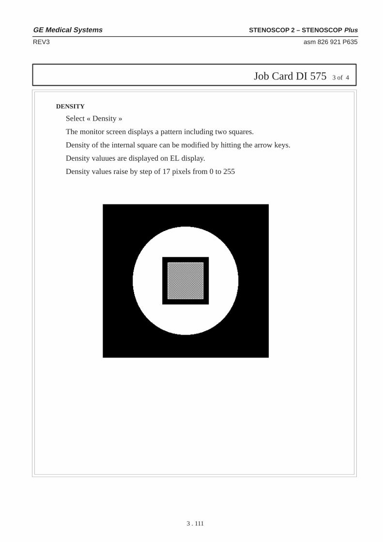
Job Card DI 5753 of 4
GE Medical Systems STENOSCOP 2 – STENOSCOP Plus
REV3 asm 826 921 P635
3 . 111
DENSITY
Select « Density »
The monitor screen displays a pattern including two squares.
Density of the internal square can be modified by hitting the arrow keys.
Density valuues are displayed on EL display.
Density values raise by step of 17 pixels from 0 to 255

Job Card DI 5754 of 4
GE Medical Systems STENOSCOP 2 – STENOSCOP Plus
REV3 asm 826 921 P635
3 . 112
GLOBAL
Select « Global »
The monitor screen displays a pattern including different squares withdifferent densities.

Version No.: 0
STENOSCOP 2 6000/9000 C.C.D. – M.D.AJob Card DI 576 1 of 4
Purpose: IMAGE QUALITYFTM MEASUREMENT Date: January 1997
Time: Manpower:
GE Medical Systems STENOSCOP 2 – STENOSCOP Plus
REV3 asm 826 921 P635
3 . 113
SECTION 1TOOLS REQUIRED
– Standard tool kit.– Funck pattern type 23
SECTION 2PRELIMINARY PRECAUTIONS
1. Set the unit with II top side
2. Do not rotate the image when making FTM measurement
3. Noise reduction (FNR) must be set at 16
4. Read the safety precautions concerning X–ray systems.
SECTION 3PROCEDURE
1. Set a 1mm copper plate over the X–ray tank and the Funck pattern with 0.6 L/cm or 1.2 L/cm areacentered over the image intensifier.
2. Select Auto fluoro on the Stenoscop console.
3. Select the Service menu by hitting the following keys:– SYSTEM PARAMETER – PERMANENT DATA – SERVICE MENU
4. Enter the password « PEGASE » in capital letter.
5. Select « Image quality » menu.
Note: The screen layout on MDA may have changed.

Job Card DI 5762 of 4
GE Medical Systems STENOSCOP 2 – STENOSCOP Plus
REV3 asm 826 921 P635
3 . 114
6. Select « FTM »
7. Monitor A screen displays 3 different ROI and the following screen is displayed on the EL.
8. Make fluoro during 3s
9. Select « White » on the touch screen.
10. Electroluminescent displays the following screen
Move the selected ROI to the white part of the picture (see ill.1).

Job Card DI 5763 of 4
SYST ID:
FE ID:
FTM
GE Medical Systems STENOSCOP 2 – STENOSCOP Plus
REV3 asm 826 921 P635
3 . 115
11. Size the ROI to 32p/32p
12. Mean and RMS values are displayed on A.screen (density value must be close to 100 +/– 10). If value is not correct, adjust mA in manual fluoro.
13. Hit the « Valid key » to go back to FTM main menu
14. Select « Black » on the touch A screen.
15. Move the ROI to the black part of the picture (see ill.1) .
16. Size the ROI to 16p/16p
17. Mean and RMS values are displayed on a screen (density value must be close to 20)
18. Hit the « Valid key » to go back to FTM main menu
19. Select « FTM » on the touch screen.
20. Move the ROI to level 0.6 lines/mm on the picture (see ill.1).
21. Size the ROI to 8p height max value centered on 0.6 l / mm
22. Mean and RMS values are displayed on a screen (level must be close to 95)
23. Result of FTM is displayed on the right upper part of A monitor
24. Hit the « Valid key » to go back to FTM main menu

Job Card DI 5764 of 4
Results Measure Specification
16 cm FIELD 20 25
22 cm FIELD 12 15
FTM @ 1.2 lp/mm % min (%) typ (%)
16 cm FIELD 50 55
22 cm FIELD 40 45
FTM @ 0.6 lp/mm % min (%) typ (%)
GE Medical Systems STENOSCOP 2 – STENOSCOP Plus
REV3 asm 826 921 P635
3 . 116

Version No.: 0
STENOSCOP 2 6000/9000 C.C.D. – M.D.AJob Card DI 577 1 of 3
Purpose: MEASUREMENT OF DENSITY ANDRESOLUTION UNIFORMITY Date: January 1997
Time: Manpower:
GE Medical Systems STENOSCOP 2 – STENOSCOP Plus
REV3 asm 826 921 P635
3 . 117
SECTION 1TOOLS REQUIRED
– Standard tool kit.– MS3 leeds pattern
SECTION 2PRELIMINARY PRECAUTIONS
1. Set the unit with II top side
2. Do not rotate the image when making measurement
3. Set the noise reduction to level 16
4. Open the collimator blades full size
SECTION 3PROCEDURE
1. Select the Service menu by hitting the following keys:– SYSTEM PARAMETER – PERMANENT DATA – MENU SERVICE
2. Enter the password « PEGASE » in capital letter.
3. Select « Image quality » menu.

Job Card DI 5772 of 3
50 Hz 60 Hz
Mmax – MminMmax
<= 20 % for 16 cm<= 25 % for 22 cm
GE Medical Systems STENOSCOP 2 – STENOSCOP Plus
REV3 asm 826 921 P635
3 . 118
16 cm field
1. Run auto fluoro during 3 sec. with two mm copper on the X–ray tank.
2. Select ROI
3. Set a 50x50 ROI
4. Check that the grey level is close 100 +/– 4
5. If the value is not correct, set the unit in manual fluoro and adjust mA to reach 100 +/– 4
4. Select « UNIFORMITY »
5. Select « UNIFORMITY »
6. Monitor A screen displays 9 ROI
UNIFORMITY OF DENSITY
1. Make fluoro during 3s
2. Read the values displayed on the different boxes.
3. Check that the maximum difference between two values is :
22 cm field
Run the same procedure.

Job Card DI 5773 of 3
��/Mmax) – ��/Mmin)��/Mmax)
<= 40 %
GE Medical Systems STENOSCOP 2 – STENOSCOP Plus
REV3 asm 826 921 P635
3 . 119
UNIFORMITY OF RESOLUTION
1. Set the MS3 pattern on the II.
2. Select Auto fluoro on the Stenoscop console.
3. Make fluoro in auto mode
4. Read the values displayed on the different boxes.
5. Check that the maximum difference between two values is :

GE Medical Systems STENOSCOP 2 – STENOSCOP Plus
REV3 asm 826 921 P635
3 . 120
Blank page

Version No.: 0
STENOSCOP 2 6000/9000 C.C.D. – M.D.AJob Card DI 578 1 of 4
Purpose: ERROR MESSAGES AND BEEP CODES OFTHE PC Date: January 1997
Time: Manpower:
GE Medical Systems STENOSCOP 2 – STENOSCOP Plus
REV3 asm 826 921 P635
3 . 121
SECTION 1PREREQUISITES
Errors can occur during POST ( Power On Self Test ) which is performed every time the system ispowered on. Fatal errors, which prevent the system to continue the boot process, are communicatedthrough a series of audible beeps. Other errors are displayed on electroluminiscent display in thefollowing format :
ERROR Message Line 1ERROR Message Line 2
For most displayed error messages, there is only one message. If a second message appears, it is“RUN SETUP”. If this message occurs, press <F1> to run BIOS Setup.(A keyboard has to be connected on the PC memory)
Beep Codes
��� ����� ���� ��������� �������
)*4)5, �%-/74) ",) 0)024; 4)*4)5, '-4'7-64; 21 6,) 026,)4<&2%4( -5 *%7/6;�
)3/%') ��
�%4-6; �4424 �%4-6; -5 126 5733246)( 21 6,-5 342(7'6� )4424 9-//124 2''74�
)3/%') ��
� �%5) �� �& �)024; �%-/74) �)024; *%-/74) -1 6,) *-456 �� �& )3/%') ��
� "-0)4 �26 �3)4%6-21%/ �)024; *%-/74) -1 6,) *-456 �� �& 2* 0)024;� 24"-0)4 21 6,) 026,)4&2%4( -5 126 *71'6-21-1+�
)3/%') ��
�42')5524 �4424 ",) ��# +)1)4%6)( %1 )4424� )3/%') ��
� ��� � �%6) �� �%-/74) ",) .);&2%4( '21642//)4 ����� 0%; &) &%(�",) ���! '%1126 59-6', 62 3426)'6)( 02()�
)3/%') ��
� �42')5524 �:')36-21 �16)4473�4424
",) ��# +)1)4%6)( %1 ):')36-21 -16)44736� )3/%') ��
� �-53/%; �)024; )%(�$4-6)�4424
",) 5;56)0 8-()2 %(%36)4 -5 )-6,)4 0-55-1+ 24 -650)024; -5 *%7/6;� ",-5 -5 126 % *%6%/ )4424�
)3/%') ��
� �� �,)'.570 �4424 �� ',)'.570 8%/7) (2)5 126 0%6', 6,) 8%/7))1'2()( -1 ���!�
)3/%') ��
� ���! !,76(291 )+-56)4 (�$46 �4424
",) 5,76(291 4)+-56)4 *24 ���! �� *%-/)(� )3/%') ��
�%',) )4424 � �:6)41%/ �%',)�%(
",) ):6)41%/ '%',) -5 *%7/6;� )3/%') ��

GE Medical Systems STENOSCOP 2 – STENOSCOP Plus
REV3 asm 826 921 P635
3 . 122
Error Messages
� � ������� �������� ������
�� �!3% � �� �11.1 �!3% �� .- 3(% *%8".!1$ #.-31.++%1 � ��� )2 -.3 6.1*)-'��%/+!#% 3(% ���
�%/+!#% ��
�$$1%22 �)-% �(.13 � �11.1 )- 3(% !$$1%22 $%#.$)-' #)1#4)318 .- 3(% ,.3(%1".!1$� �%/+!#% ��
�!#(% �%,.18 �!$� �.�.3 �-!"+% �!#(% �
�!#(% ,%,.18 )2 $%&%#3)5%� �%/+!#% )3� �%/+!#% ��
���� �),%1 �11.1 �.23 �� 2823%,2 )-#+4$% 36. 3),%12� �(%1% )2 !- %11.1 )-3),%1 ��
�%/+!#% ��
���� �!33%18 �3!3% �.6 ���� ��� )2 /.6%1%$ "8 ! "!33%18� �(% "!33%18 /.6%1)2 +.6�
�%/+!#%�!33%18
���� �(%#*24, �!)+41%�&3%1 ���� ��� 5!+4%2 !1% 2!5%$� ! #(%#*24, 5!+4% )2 '%-:%1!3%$ &.1 %11.1 #(%#*)-'� �(% /1%5).42 5!+4% )2 $)&&%1%-3&1., 3(% #411%-3 5!+4%� �4- ������� �%34/�
�%/+!#%���
���� �823%, �/3).-2�.3 �%3
�(% 5!+4%2 23.1%$ )- ���� ��� !1% %)3(%1 #.114/3 .1-. %7)23%-3� �4- �%34/�
�%/+!#%���
���� �)2/+!8 �8/% �)2:,!3#(
�(% 5)$%. 38/% )- ���� ��� $.%2 -.3 ,!3#( 3(% 38/%$%3%#3%$ "8 3(% ����� �4- ������� �%34/�
�%/+!#%���
�����%,.18 �)9% �)2:,!3#(
�(% !,.4-3 .& ,%,.18 .- 3(% ,.3(%1".!1$ )2 $)&&%1%-3 3(!-3(% !,.4-3 )- ���� ���� �4- ������� �%34/�
�%/+!#%���
���� �),% !-$ �!3%�.3 2%3
�4- �3!-$!1$ ���� �%34/ 3. 2%3 3(% $!3% !-$ 3),% )-���� ����
�)2*%33% �..3 �!)+41%�(% "..3 $)2* )- &+.//8 $1)5% �� )2 #.114/3� �3 #!--.3 "% 42%$3. "..3 3(% 2823%,� 2% !-.3(%1 "..3 $)2* !-$ &.++.6 3(%2#1%%- )-2314#3).-2�
�)2/+!8 �6)3#( �.3�1./%1
�.,% 2823%,2 1%04)1% ! 5)$%. 26)3#( .- 3(% ,.3(%1".!1$"% 2%3 3. %)3(%1 #.+.1 .1 ,.-.#(1.,%� �41- 3(% 2823%, .&&�2%3 3(% 26)3#(� 3(%- /.6%1 .-�
��� ����� �11.1 )- 3(% ��� #.-31.++%1� �%/+!#% ��
��� � ����� �11.1 )- 3(% &)123 ��� #(!--%+� �%/+!#% ��
��� �� ����� �11.1 )- 3(% 2%#.-$ ��� #(!--%+� �%/+!#% ��
��� �.-31.++%1 �!)+41%�(% ���� #!--.3 #.,,4-)#!3% 6)3( 3(% &+.//8 $)2* $1)5%#.-31.++%1� �(%#* !++ !//1./1)!3% #.--%#3).-2 !&3%1 3(%2823%, )2 /.6%1%$ $.6-�
�%/+!#% ��
��� �.-31.++%1 �!)+41%�(% ���� #!--.3 #.,,4-)#!3% 6)3( 3(% (!1$ $)2* $1)5%#.-31.++%1� �(%#* !++ !//1./1)!3% #.--%#3).-2 !&3%1 3(%2823%, )2 /.6%1%$ $.6-�
�%/+!#% ��
Job Card DI 5782 of 4

GE Medical Systems STENOSCOP 2 – STENOSCOP Plus
REV3 asm 826 921 P635
3 . 123
Error Messages
����� ���� ����� ���� �������
��!� � �4424 �16)44736 ',%11)/ *%-/)( �� !� �)3/%') ��
��!� � �4424 �16)44736 ',%11)/ *%-/)( �� !� �)3/%') ��
�18%/-( �226 �-5.)66) !,) ��� '%1 4)%( 6,) (-5. -1 */233; (4-8) � � &76 '%1126&226 6,) 5;56)0� "5) %126,)4 &226 (-5.�
��
�);&2%4( �5 �2'.)(���"1/2'. �6
!,) .);&2%4( /2'. -5 6,) 5;56)0 -5 )1+%+)(� !,) 5;56)00756 &) 71/2'.)( 62 '216-17)�
��
�);&2%4( �4424 !,)4) -5 % 6-0-1+ 342&/)0 9-6, 6,) .);&2%4(� )6 6,)�);&2%4( 236-21 -1 6%1(%4( ��� )673 62 �26 �16%//)(62 5.-3 6,) .);&2%4( �� ! 4276-1)5�
��
�� � �16)4*%') �4424 !,)4) -5 %1 )4424 -1 6,) .);&2%4( '211)'624� ��
�** �2%4( �%4-6; �4424 �%4-6; )4424 -1 0)024; -156%//)( -1 %1 ):3%15-21 5/26�!,) *240%6 -5
��� ����� ����!$ ����� ���� ���#� � �####�
#### -5 6,) ,): %((4)55 9,)4) 6,) )4424 2''74)(�
�)3/%') ��
�1 �2%4( �%4-6; �4424 �%4-6; -5 126 5733246)( 21 6,-5 342(7'6� )4424 9-// 126 2''74�
�%4-6; �4424 ���� �%4-6; )4424 -1 5;56)0 0)024; %6 %1 71.1291 %((4)55� �)3/%') ��
ISA NMI Messages
��� ��� ���� ����� ���� �������
�)024; �%4-6; �4424 %6:::::
�)024; *%-/)(� �* 6,) 0)024; /2'%6-21 '%1 &) ()6)40-1)(� -6-5 (-53/%;)( %5 :::::� �* 126� 6,) 0)55%+) -5 �)024; �%4-6;�4424�����
�)3/%') ��
��� �%4( �%4-6; �4424 %6:::::
�1 ):3%15-21 '%4 *%-/)(� �* 6,) %((4)55 '%1 &) ()6)40-1)(�-6 -5 (-53/%;)( %5 :::::� �* 126� 6,) 0)55%+) -5 ��� �%4( �%4-6;�4424������
�)3/%') ��
��� �75 !-0)�276 � ()8-') ,%5 (4-8)1 6,) &75 5-+1%/ *24 024) 6,%1��� 0-'425)'21(5�
�)3/%') ��
Job Card DI 5783 of 4

GE Medical Systems STENOSCOP 2 – STENOSCOP Plus
REV3 asm 826 921 P635
3 . 124
Plug and Play Error Messages
��� � ������ �������� � � ��� �
� � # ��� �$0( * ���'$")13+
�'$ 1$0( * �� "'$")13+ -% �*3& ,# �* 6 " 0# 5 1 (,4 *(#� �$.* "$ ��
� �*-..6 �(1) �-,20-**$0�$1-30"$ �-,%*("2
�'$ %*-..6 #(1) "-,20-**$0 ' 1 0$/3$12$# 0$1-30"$ 2' 2 (1 *0$ #6 (, 31$�
�$.* "$ ��
� ��� � �'$")13+�00-0���� � �*$ 0$#
�'$ ���� # 2 5 1 0$(,(2( *(7$# !$" 31$ -% , ��� �"'$")13+ $00-0� �06 0$03,,(,& 2'$ ����
�$.* "$ ��
� ��� � �*$ 0$# !6�3+.$0
�'$ 8�*$ 0 ����� 15(2"' ' 1 !$$, +-4$# 2- 2'$ ��.-1(2(-, ,# ���� � � ' 1 !$$, "*$ 0$#�
�$.* "$ ��
��� �� 2 �,4 *(#���� � �*$ 0$#
�,4 *(# $,206 (, 2'$ ���� 0$ � �
� 0 **$* �-02 �$1-30"$�-,%*("2
�'$ . 0 **$* .-02 ' 1 0$/3$12$# 0$1-30"$ 2' 2 (1 *0$ #6 (, 31$� �
��� �00-0 �-& (1 �3** �'(1 +$11 &$ (1 #(1.* 6$# 5'$, +-0$ 2' , � ��� "-,%*("2 $00-01 0$ #$2$"2$#� �- ##(2(-, * ��� $00-01 " , !$ *-&&$#�
�$.* "$ ��
��� ��� �-02 �-,%*("2 �5- #$4("$1 0$/3$12$# 2'$ 1 +$ 0$1-30"$� 0$13*2(,& (, "-,%*("2� �$.* "$ ��
��� ��� �-,%*("2 �5- #$4("$1 0$/3$12$# 2'$ 1 +$ 0$1-30"$� 0$13*2(,& (, "-,%*("2� �$.* "$ ��
�0(+ 06 �$+-06 �-,%*("2 �5- #$4("$1 0$/3$12$# 2'$ 1 +$ 0$1-30"$� 0$13*2(,& (, "-,%*("2� �$.* "$ ��
�0(+ 06 �--2 �$4("$ �-2�-3,#
�'$ #$1(&, 2$# .0(+ 06 !--2 #$4("$ �' 0# #(1) #0(4$� #(1)$22$#0(4$� -0 ������ #0(4$� "-3*# ,-2 !$ %-3,#�
�$.* "$ ��
�0(+ 06 ��� �-,20-**$0�$1-30"$ �-,%*("2
�'$ .0(+ 06 ��� "-,20-**$0 ' 1 0$/3$12$# 0$1-30"$ 2' 2 (1 *0$ #6 (, 31$�
�$.* "$ ��
�0(+ 06 �,.32 �$4("$ �-2�-3,#
�'$ #$1(&, 2$# .0(+ 06 (,.32 #$4("$ �)$6!- 0#� +-31$� -0 -2'$0�(% (,.32 (1 0$#(0$"2$#� "-3*# ,-2 !$ %-3,#�
�
�$"-,# 06 ��� �-,20-*9*$0 �$1-30"$ �-,%*("2
�'$ 1$"-,# 06 ��� "-,20-**$0 ' 1 0$/3$12$# 0$1-30"$ 2' 2 (1 *0$ #6 (, 31$�
�
�$0( * �-02 �$1-30"$�-,%*("2
�$0( * .-02 ' 1 0$/3$12$# 0$1-30"$ 2' 2 (1 *0$ #6 (, 31$� �$.* "$ ��
�$0( * �-02 �$1-30"$�-,%*("2
�$0( * .-02 ' 1 0$/3$12$# 0$1-30"$ 2' 2 (1 *0$ #6 (, 31$� �$.* "$ ��
�2 2(" �$4("$ �$1-30"$�-,%*("2
,-,��*3& ,# �* 6 �� " 0# ' 1 0$/3$12$# 0$1-30"$ 2' 2 (1 *0$ #6 (, 31$�
�$.* "$ ��
�612$+ �- 0# �$4("$�$1-30"$ �-,%*("2
,-,��*3& ,# �* 6 1612$+ 0$1-30"$ ' 1 0$/3$12$# 0$1-30"$2' 2 (1 *0$ #6 (, 31$�
�$.* "$ ��
� � �'-3*# ,-2 ' ..$, � (% ' ..$,� "' ,&$ 2'$ ���
Job Card DI 5784 of 4

Version No.: 0
STENOSCOP 2 6000/9000 C.C.D. – M.D.AJob Card DI 579 1 of 2
Purpose: TOUCH SCREEN CALIBRATIONDate:
Time: Manpower:
GE Medical Systems STENOSCOP 2 – STENOSCOP Plus
REV3 asm 826 921 P635
3 . 125
SECTION 1SUPPLIES
None.
SECTION 2TOOLS
None.
SECTION 3SAFETY PRECAUTIONS
None.
SECTION 4PROCEDURE
1. Switch the unit ON
2. Enter the service menu (system setup / permanent data).
3. Press the « Calibrate touch screen » key
4. The following screen will appear :
Note: Screen layout on MDA may have changed.
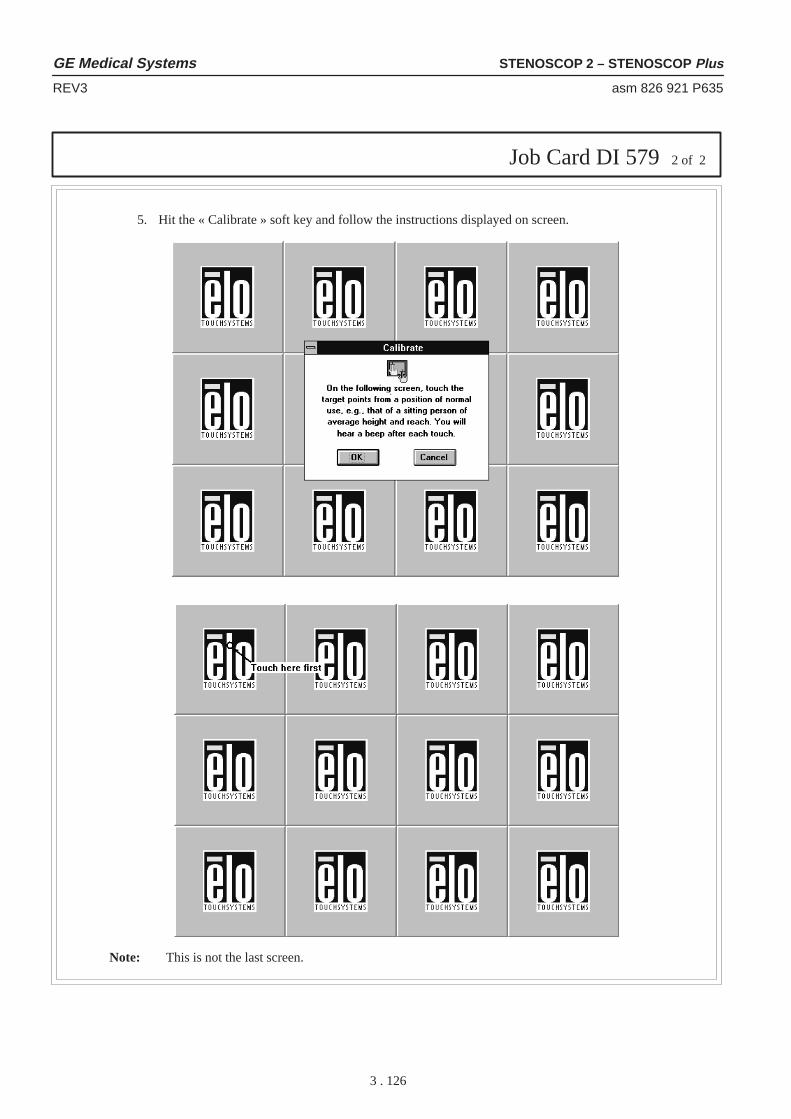
Job Card DI 5792 of 2
GE Medical Systems STENOSCOP 2 – STENOSCOP Plus
REV3 asm 826 921 P635
3 . 126
5. Hit the « Calibrate » soft key and follow the instructions displayed on screen.
Note: This is not the last screen.