ge digital energy - ge grid solutions · g imagination at work ge digital energy innovative...
TRANSCRIPT

g imagination at work
GEDigital Energy
Innovative Technology & Design • Advanced motor protection, control and
diagnostics capability • Patented environmental monitoring and
diagnostics• Advanced, flexible and embedded
communications: IEC® 61850 Ed2, IEC 62439/PRP, Modbus® RTU & TCP/IP, DNP3.0, IEC 60870-5-104
• Single setup and configuration across the platform
• Elimination of electrolytic capacitors• Field swappable power supply• Enhanced relay draw-out construction
Exceptional Quality & Reliability • IPC A-610-E Class 3 manufacturing standards• Highest reliability standards for electronics
testing• 100% Environmental Stress Screening and full
functional testing• Rated for IP54 (front) applications• Standard Harsh Environment Conformal
Coating
Uncompromising Service & Support • Covered under GE’s 10 year warranty plan• Designed, tested and manufactured by GE
Multilin™ 869Comprehensive Motor Protection and Management for Medium and Large Motors
The Multilin 869 relay is a member of the Multilin 8 Series protective relay platform and has been designed for the protection, control and management of medium and large induction and synchronous motors.
The Multilin 869 provides advanced functionality for various types of applications such as high-speed protection, extensively customizable programmable logic, advanced motor monitoring and diagnostics, and flexible configuration capabilities.
Advanced communications of the 8 Series platform allows easy integration into process and electrical control systems for smoother asset monitoring and control.
Key Benefits• Comprehensive motor protection for medium and large induction motors
• Advanced motor diagnostics with high-end fault and disturbance recording
• High-end cyber security such as AAA, Radius, RBAC, and Syslog helps enable NERC® CIP requirements
• Draw-out design simplifies testing and increases process uptime
• Wi-Fi connectivity minimizes system configuration and facilitates quick/easy relay programming and diagnostic retrieval
• Monitored environmental conditions helps reduce system downtime
Key Applications• Wide range of motor applications for oil & gas, mining & metals, cement,
and wastewater
• Comprehensive protection and management of medium to large motors; two-speed, VFD-driven, cyclic loading and synchronous motors
• Specific and advanced features for high inertia loads and reduced-voltage starting motors
• Stator protection of medium to large synchronous motors where field functions are provided by excitation panels
• Advanced predictive motor diagnostics and motor health visualization
WORLDWIDE
WARRANTY
10YEAR

2 GEDigitalEnergy.com
Multilin 869 – Motor Protection System
Multilin 8 Series Platform OverviewFrom oil pumping and refining facilities, to open pit or underground mining and processing operations, to distribution utilities, companies demand solutions that ensure maximum process uptime, minimum operational and maintenance efforts, and have the durability to withstand harsh environmental conditions.
The Multilin 8 Series is GE’s next-generation protection and control relay platform designed for industrial and distribution utilities. The platform provides comprehensive protection and asset monitoring for critical feeders, motors, generators, and transformers.
Multilin 8 Series Platform - Application Example
The 8 Series is designed to solve the challenges that customers face in running their day-to-day operations including maximizing system and process uptime, simplifying system integration and maintenance, and extending the life of critical assets. Utilizing advanced design practices, superior technology (elimination of all electrolytic capacitors), and state-of-the art test and manufacturing facilities, GE is raising the bar on system performance and reliability.
With advanced communications the 8 Series integrates easily and seamlessly into your new or existing control system, along with your other Multilin protection devices, providing a comprehensive solution for the end-to-end electrical system within your operations.

3GEDigitalEnergy.com
Multilin 869 – Motor Protection System
Exceptional Quality & ReliabilityIndustry-leading quality, reliability and design processes are at the core of GE’s next generation protective relay platform. With significant investments in state-of-the-art type test facilities that simulate a complete range of operating environments and manufactured to the IPC A-610 Class 3 standard, adhering to the highest reliability standards and ensuring rugged performance, each device completes Environmental Stress Screening prior to shipping from GE’s facility.
The Multilin 8 Series Protection Relays are manufactured in an ISO® 9001:2008 certified manufacturing facility.
Pioneering Technology & DesignThe Multilin 869 is part of the 8 Series platform that provides comprehensive, high performance protection and control for feeder, motor, transformer and generator applications.
The Multilin 869 Motor Protection System offers a powerful solution for critical motor protection applications with advanced thermal model and voltage dependant curves for high inertial loads.
Utilizing decades of experience in motor protection, GE has implemented ease-of-use features, such as single screen set-ups delivering faster motor configuration and startup and motor health reports providing detailed motor diagnostic enabling quick and easy identification of motor issues.

4 GEDigitalEnergy.com
Multilin 869 – Motor Protection System
No Electrolytic Capacitors Increasing quality and reliability for continuous plant operations
Robust Extruded Aluminum ChassisCustom-designed extruded aluminum chassis delivering optimal thermal management to extend component life
3
5
5
IPC A-610 Class 3 ManufacturingDrives to the highest level of reliability standards delivering rugged performance
4
Draw-OutProviding simplified device fleet management
6
Field Swappable Power SupplyExtends the usable life of the protection relay and minimizes costly, time consuming replacement and re-configuration.
1
Harsh Environment Conformal CoatingStandard on all printed circuit boards delivering higher reliability and extended relay life
2
21
643
The Mutilin 8 Series products have an integrated protection integrity engine that utilizes customized algorithms, providing advanced diagnostics to ensure asset protection is not compromised.
Maintaining and safeguarding the electrical supply of an operation is critical to ensuring maximum process availability and performance.
The 8 Series incorporates the latest cyber security features, including password complexity, RADIUS authentication and role-based access control (RBAC), enabling customers to comply with NERC CIP and NISTIR 7628 requirements.
Understanding that customers need protection and control devices that must reliably operate in harsh and challenging environments, GE delivers the Multilin 8 Series with harsh conformal coating on all printed circuit boards and a patented environmental awareness module that provides real-time detection of environmental factors that affect product life, as part of its standard offering, delivering higher reliability and extended relay life.
Uncompromised Reliability & Service Designed, manufactured and tested to industry standards at our state-of-the-art facilities, the Multilin 8 Series delivers maximum performance for today’s most demanding environments.
In addition to the superior technology and innovative design advancements that enable delivery of uncompromised performance and reliability, the Multilin 8 Series is also backed by GE’s 10 year warranty plan.
Multilin 869 Overview Motors are the workhorses of any industrial plant . Industrial facilities depend on reliable and secure motor operation to keep their processes running. Regardless of the type of motor, the load it runs or the process requirements, a fully integrated protection and control scheme is critical to maintaining uninterrupted service to the entire facility.
The Multilin 869 Motor Protection System is a protection device designed for the management , protection and control of medium to large horsepower motors. The 869 provides comprehensive protection and control of various types of motors with different loads they run.
The 869 relay offers the ideal solution for protecting, monitoring and controlling motors from disturbances or faults. With a fast protection pass, running every 1/8th of a cycle, the 869 relay provides faster current, voltage, power and frequency protection elements. Supporting the latest in industry standard communication protocols, including IEC 62439/PRP and IEC 61850 Ed2, the Multilin 869 relay easily integrates into new or existing networks.
The 869 is an advanced motor protection relay that provides high performance protection, high-density I/O, extensive programmable logic and flexible configuration capabilities. With protection and control logic, the 869 allows for simplified coordination with upstream and downstream disconnect devices. The 869 also offers enhanced features, such as diagnostics, preventative maintenance, condition monitoring, security, and advanced communications options.

5GEDigitalEnergy.com
Multilin 869 – Motor Protection System
Protection & ControlAs part of the 8 Series family, the Multilin 869 provides superior protection and control. The 869 offers comprehensive protection and control solutions for medium and large motors for various applications. It contains a full range of selectively enabled, self contained protection and control elements.
Motor Thermal ModelMany motor failures are directly or indirectly related to, or caused by, extensive heating of the different motor parts involved in electromechanical operation. Proven through several generations of GE’s Multilin motor relays, an enhanced thermal model is used in the 869 relay with seven major features:
• Motor thermal limit curves - NEMA® standard, voltage dependent and customized motor curves
• IEC 60255-8 thermal overload curves
• Smoothing filter for cyclic loads
• Current unbalance biasing
• Independent running and stopped exponential cooling curves
• Optional RTD biasing of the thermal model to adapt to real-time temperature measurements
• Compensation for hot/cold motor condition
The flexibility of the Multilin 869 thermal models will allow proper set up and performance for applications, including high inertia and cyclic loads.
Multilin 869 – Advanced Thermal Model High inertia overload curves sample, 8500HP, 13.2kV, Reactor coolant Pump
Stator DifferentialDifferential protection is considered as the first line of protection for internal phase-to-phase or phase-to-ground faults for medium and large motors to provide sensitive and fast clearing protection against winding faults including turn-to-turn faults. The Multilin 869 provides two flavors of the stator current differential protection:
Traditional dual slope percent differential enhanced with CT saturation detection and directional check for both AC and DC saturation providing exceptional security without sacrificing sensitivity.
Core balanced differential protection enhanced with biasing during motor starting to inhibit differential protection during motor starting when inrush currents may upset differential protection.
All differential values are available in metering and oscillography allowing easy testing and troubleshooting.
Multilin 869 Stator DifferentialTwo-CT set and Core-Balanced configurations

6 GEDigitalEnergy.com
Multilin 869 – Motor Protection System
Functional Block Diagram
VFD-Driven MotorsThe Multilin 869 provides protection for motors fed through VFDs (Variable Frequency Drives). A wide range of the frequency tracking (3-72Hz) allows the 869 to track the motor frequency and adjust its sampling rate to accurately measure phasors. An advanced algorithm allows switchable current and voltage tracking in case VFD is bypassed.
To provide even more accurate phasor measurement , there is an option that filters ripples in phasors due to harmonics for major motor functions. Additionally, users may indicate a starting VFD frequency that helps the device to track the motor frequency faster and eliminate unnecessary delay in the averaging filter during motor startup that can cause delayed protection operation during motor failures.
Reduced Voltage StartingThe Multilin 869 can control the transition of a reduced voltage starter from reduced to full voltage based on “Current Only”, “Current and Time”, or “Current or Timer”. During this process, the relay continuously monitors the motor current to ensure an effective transition.
Multilin 869 – VFD Driven Motor Protection with or without bypass switch
DEVICE # FUNCTION
14 Under speed
19 Motor Starter
27P Phase Undervoltage
32P Directional Power
37 Undercurrent
37P Underpower
38 Bearing Temperature
46 Current Unbalance
47 Voltage Reversal
49 Thermal Model
DEVICE # FUNCTION
50P Mechanical Jam
50P Motor Overload Alarm
50P Motor Short Circuit
50 P/N/G
Phase/Neutral/Ground Instantaneous Overcurrent
50_2 Negative Sequence Instantaneous Overcurrent
50LR Acceleration Time
51 P/N/G
Phase/Neutral/Ground Time Overcurrent
51G Motor Ground Fault
DEVICE # FUNCTION
51V Voltage Restrained Phase Time Overcurrent
55 Power Factor
59P Phase Overvoltage
59N Neutral Overvoltage
59_2 Negative Sequence Overvoltage
59X Auxiliary Overvoltage
66 Maximum starting rate
66 Time Between Starts
DEVICE # FUNCTION
67P Phase Directional Overcurrent
67N Neutral Directional Overcurrent
81 O/U Over/Under frequency
86 Lock-out
87S Percent Differential
VTFF Fuse Failure
RTD Protection
Thermal Inhibit

7GEDigitalEnergy.com
Multilin 869 – Motor Protection System
Two-Speed Thermal ModelThe two-speed motor protection feature allows for the protection of motors that can operate at two different speeds. The algorithm integrates the heating at each speed into one thermal model.
The Multilin 869 automatically determines which settings should be active at any given time considering a transition from speed one to speed two within a period of time. The device has all required logic and time delays to safely transfer speeds.
Protection of Motors with High-Inertia LoadsThe voltage dependent overload curve feature is tailored to protect motors which are used in high inertia load applications.
Voltage is continually monitored when the motor is started and during acceleration. The thermal limit curve is then adjusted accordingly. This enables the Multilin 869 to distinguish between a locked rotor condition, an accelerating condition and a running condition.
RTD ProtectionThe Multilin 869 supports up to 12 programmable RTD inputs that can be configured for an Alarm or Trip. The RTD voting option gives additional reliability to ignore any RTD failures.
The RTDs can be assigned to a group for monitoring the stator, bearing and ambient temperatures.
RTD
The
rmal
Cap
acity
Use
d (%
)
RTD Bias Maximum
RTDBias Minimum
RTDBias Center Point
100
90
80
70
60
50
40
30
20
10
0-50 0 50 100 200 250150
Maximum Stator RTD Temperature ( C)
RTD bias curve
Underpower ProtectionThe Underpower element in the 869 is based on the three-phase real power (kW) measured from the phase currents and voltages. Underpower may be used to detect loss of load conditions. This may be used for more sensitive detection of load loss or pump cavitation or detecting process related issues.
Voltage and Frequency ProtectionThe voltage and frequency protection functions detect abnormal system conditions like over/under voltage, over/under frequency and/or phase reversal that are potentially hazardous to the motor.
Undercurrent ProtectionThe undercurrent protection element provides the ability to trip the motor due to external conditions that can cause the load being driven by the motor to drop below a pre-set level. This function is used to protect pumps from loss of suction, fans from loss of airflow due to a closed damper or a conveyor system due to a broken belt .
Motor Start SupervisionMotor start supervision consists of the following features: Time-Between-Starts, Start-per-Hour, Restart Time and Start Inhibit . These elements are intended to guard the motor against excessive starting duty, which is normally defined by the motor manufacturer in addition to the thermal damage curves. The Emergency Restart enables the user to reset the Motor start supervisions in case of process needs.
The start inhibit function prevents the starting of a motor when the motor is too hot and does not have a sufficient amount of thermal capacity available to allow a start without being tripped offline. In case of emergency, the thermal capacity used and motor start supervision timers can be reset to allow a hot motor to start.

8 GEDigitalEnergy.com
Multilin 869 – Motor Protection System
TYPICAL CUSTOM CURVE - 6500 HP, 13800 VOLT INDUCED DRAFT FAN MOTOR
10000
1000
100
10
1.0
0.10.5 1.0 10 100
MULTIPLE OF PER UNIT CURRENT
TIM
E TO
TRI
P IN
SEC
ON
DS
1
2
3
4
5
PROGRAMMED FLEXCURVE
RUNNING SAFETIME (STATOR LIMIT)
ACCELERATION SAFETIME (ROTOR LIMIT)
MOTOR CURRENT @ 100% VOLTAGE
MOTOR CURRENT @ 80% VOLTAGE
1
2
3
4
5
Typical FlexCurve overload curve.
Advanced AutomationThe Multilin 869 incorporates advanced automation capabilities that exceeds what is found in most motor protection relays. This reduces the need for additional programmable controllers or discrete control relays including programmable logic, communication, and SCADA devices. Advanced automation also facilitates the Multilin 869 to integrate seamlessly with other protection/process systems.
FlexLogic™FlexLogic is the powerful programming logic engine that provides the ability to create customized protection and control schemes, minimizing the need and associated costs of auxiliary components and wiring. Using FlexLogic, the 869 can be programmed to provide the required tripping logic along with custom scheme logic for motor breaker control
Breaker Failure ProtectionThe breaker failure protection element monitors for timely operation of the connected breaker. If a trip command is not successful in operating the breaker and clearing the fault , the breaker failure element can be used to send trip signals to upstream breakers to clear the fault .
Mechanical Jam and Acceleration TimeThese two elements are used to prevent motor damage during abnormal operational conditions such as excessively long acceleration time or stalled rotors. The mechanical jam element senses increased loading associated with process or load related faults such as an overloaded conveyor.
The Multilin 869 protects the motor from overheating in cases of abnormal loading during motor starts. The motor can be tripped if the motor does not reach a running condition within the programmable motor acceleration time.
Synchronous Motor ProtectionFor synchronous motors with excitation system control that offers field winding protection, the Multilin 869 offers comprehensive stator protection functions in addition to features such as power factor based pull out protection and reactive power based alarm and trip functions.
Adaptive ProtectionThe Multilin 869 offers effective, reliable management of motors. With dynamic, sensitive settings, the 869 provides secure and dependable protection. With six setting groups, the 869 provides the sensitive settings range and groups required to ensure no compromise is made to meet changing system conditions. These setting groups can be enabled automatically or manually via digital Inputs, virtual inputs or remote communications to address system needs, ensuring greater system reliability and efficiency.
FlexCurves™For applications that require greater flexibility, FlexCurves can be used to define custom curve shapes. These curves can be used to protect motors with different rotor and stator damage curves, allowing complete protection over the total motor capacity.

9GEDigitalEnergy.com
Multilin 869 – Motor Protection System
Motor Status Summary
Overview of the 869 Motor Health Report
(including interlocking with internal motor start supervision), interlocking schemes with adjacent protections (for example, preventing sympathetic tripping of healthy feeders), and dynamic setting group changes.
FlexLogic allows the Multilin 869 to operate and control breakers and other auxiliary devices needed to fit most motor protection schemes and applications
Monitoring & DiagnosticsThe Multilin 869 includes high accuracy metering and recording for all AC signals. Voltage, current, and power metering are built into the relay as a standard feature. Current and voltage parameters are available as total RMS magnitude, and as fundamental frequency magnitude and angle.
Advanced Motor DiagnosticsThe Multilin 869 provides advanced motor diagnostics including a broken rotor bar detection function. The broken rotor bar detection is a condition monitoring function that continuously monitors the motor’s
health while in operation. The advanced Motor Current Signature Analysis (MCSA) continuously analyzes the motor current signature and based on preset algorithms will determine when a broken rotor bar is present in the motor.
With fully programmable alarms, the broken rotor bar function will provide early detection of rotor bar problems enabling maintenance personnel to schedule for predictive maintenance of the motor thereby preventing catastrophic motor failures.
BROKEN ROTOR BAR
DETECTION
By providing early indication of potential rotor problems, serious system issues can be avoided, such as reduced starting torque, overloads, torque and speed oscillation and bearing wear. With the broken rotor bar detection system, advanced warning of impending problems reduces catastrophic failures, maximizing motor life and system uptime.
Advanced Motor Health ReportThe 869 motor health report provides a quick snapshot of the motor operating and diagnostic information in an easy way to allow users to make decisions about health of the motor. Based on the graphical representation and trend values of the motor historical data gathered by the 869, users can quickly identify process issues and maintenance requirements before damage occurs and costly repairs are required.
Multilin 869 Motor Health ReportMotor Start Records

10 GEDigitalEnergy.com
Multilin 869 – Motor Protection System
The motor health report quickly provides a motor operation summary with detailed information in seven categories.
• Device Overview: gives general information on the motor, including requested period, user name, device name, order code, firmware version, motor and system settings, and motor total running time.
• Status Overview: summarizes the historical learned data and gives an evaluation of the status of the motor, including the oldest and latest values of acceleration time, starting current, start thermal capacity used, average motor load, and average running time.
• Trip Summary: presents a summary of the events that have tripped the motor.
• Motor Operating History: counts the amount of events in terms of Motor Starting/Running, Manual Stop Commands, Trip Commands, Lockouts, Alarm Conditions, and Emergency Restarts.
• Motor Starting Learned Data: collects the learned data, including acceleration time, starting current, start thermal capacity used, average motor load, and average running time.
• Motor Start Records: displays the start data, including average of three-phase RMS currents, current unbalance, ground current, average of three-phase RMS voltages, thermal capacity used, frequency and motor status.
• Motor Stopping/Tripping: gives details on the events that are specifically related to the stopping and tripping of the motor.
Breaker Health MonitoringThe breaker is monitored by the relay not only for detection of breaker failure, but also for the overall “breaker health” which includes:
• Breaker close and breaker open times
• Trip circuit monitoring
• Spring charging time
• Per-phase arcing current
• Trip counters
All algorithms provide the user with the flexibility to set up initial breaker trip counter conditions and define the criteria for breaker wear throughout a number of setpoints.
Multilin 8 Series Breaker Health Report available on the display or via the setup software
Environmental MonitoringThe 869 implements a patented environmental monitoring system that measures and provides operating condition information. Reliable and secure operation of the 869 relay and other electronic devices in the vicinity may be affected by environmental factors. The 869 relay has been designed to meet or exceed required industry standards. Some operating conditions may be beyond those standards and reduce total lifespan of the device.
Typical environmental conditions that may affect electronic device reliability include voltage, current , temperature, humidity, dust , contaminants, mechanical stress, shock, radiation and intensity of electrical and magnetic fields. These environmental factors are different from natural weather conditions at particular installation conditions and are beneficial to monitor. The 869 relay’s built-in environmental awareness feature (patent “Systems and methods for predicting maintenance of intelligent electronic devices”) collects the histograms of operating conditions from the point the device is put into service. Monitored environmental conditions include temperature, humidity and transient voltage. The histogram of each environmental factor may be retrieved from the diagnostic page accessed through a PC running the EnerVista Multilin 8 Series Setup program.
Environmental health report is available via Multilin PC Software
11GEDigitalEnergy.com
Multilin 869 – Motor Protection System
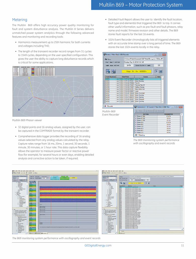
MeteringThe Multilin 869 offers high accuracy power quality monitoring for fault and system disturbance analysis. The Multilin 8 Series delivers unmatched power system analytics through the following advanced features and monitoring and recording tools:
• Harmonics measurement up to 25th harmonic for both currents and voltages including THD.
• The length of the transient recorder record ranges from 31 cycles to 1549 cycles, depending on the user specified configuration. This gives the user the ability to capture long disturbance records which is critical for some applications.
Multilin 869 Phasor viewer
• 32 digital points and 16 analog values, assigned by the user, can be captured in the COMTRADE format by the transient recorder.
• Comprehensive data logger provides the recording of 16 analog values selected from any analog values calculated by the relay. Capture rates range from 16 ms, 20ms, 1 second, 30 seconds, 1 minute, 30 minutes, or 1 hour rate. This data capture flexibility allows the operator to measure power factor or reactive power flow (for example), for several hours or even days, enabling detailed analysis and corrective action to be taken, if required.
The 869 monitoring system performance with oscillography and event records
• Detailed Fault Report allows the user to identify the fault location, fault type and element(s) that triggered the 869 to trip. It carries other useful information, such as pre-fault and fault phasors, relay name and model, firmware revision and other details. The 869 stores fault reports for the last 16 events.
• 1024 Event Recorder chronologically lists all triggered elements with an accurate time stamp over a long period of time. The 869 stores the last 1024 events locally in the relay.
Multilin 869Event Recorder
The 869 monitoring system performance with oscillography and event records
12 GEDigitalEnergy.com
Multilin 869 – Motor Protection System
CommunicationsThe 869 provides advanced communications technologies for remote data and engineering access, making it easy and flexible to use and integrate into new and existing infrastructures. Direct support for fiber optic Ethernet provides high-bandwidth communications, allowing for low-latency controls and high-speed file transfers of relay fault and event record information. The 869 also supports two independent IP addresses, providing high flexibility for the most challenging of communication networks.
Providing several Ethernet and serial port options and supporting a wide range of industry standard protocols, the 869 enables easy, direct integration into DCS and SCADA systems. The 869 supports the following protocols:
• IEC 61850 Ed2, IEC 62439 / PRP
• DNP 3.0, IEC 60870-5-103, IEC 60870-5-104
• Modbus RTU, Modbus TCP/IP
The 869 has USB front port and Wi-Fi interfaces for ease of access to the relay.
Wi-Fi Connectivity:
• Simplify set-up and configuration
• Simplify diagnostic retrieval
• Eliminate personnel in front of switchgear
• WPA-2 security
LOCAL AREA NETWORK
ALOCAL AREA NETWORK
B
ML3000SWITCHML3000
SWITCH ML3000SWITCHML3000
SWITCH
ML3000SWITCH ML3000
SWITCH
D400D400
F650 350 469 850 869 889 845 UR
SCADA EMS DMS Data Historian
Local HMI / Single Line
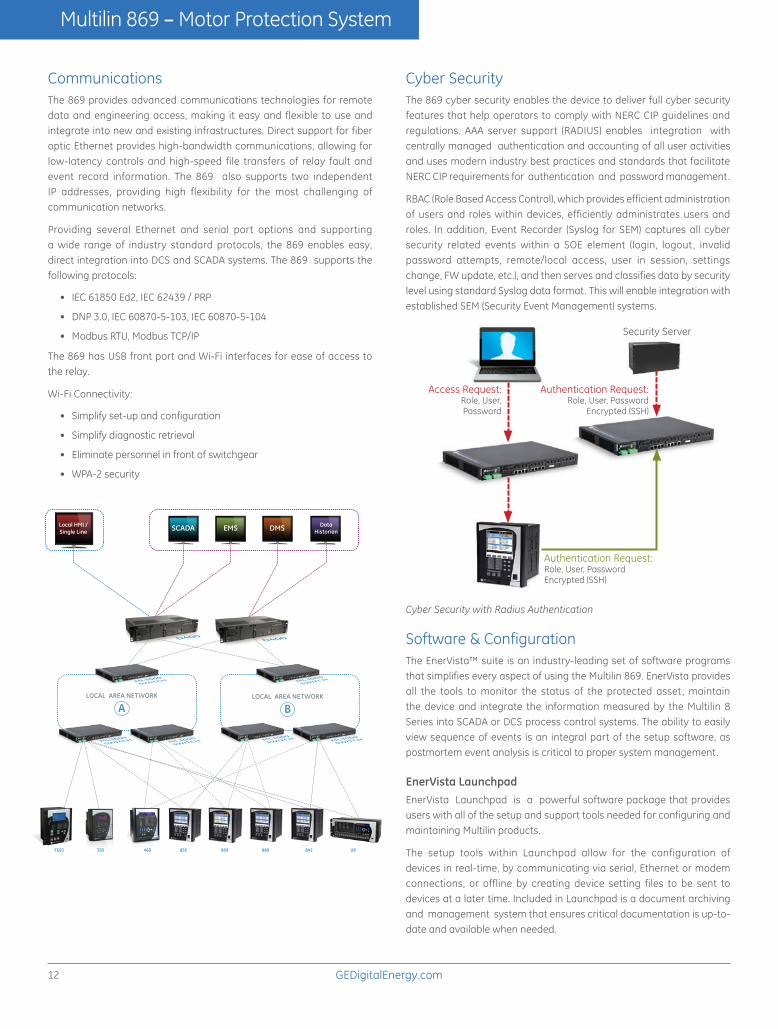
Cyber SecurityThe 869 cyber security enables the device to deliver full cyber security features that help operators to comply with NERC CIP guidelines and regulations. AAA server support (RADIUS) enables integration with centrally managed authentication and accounting of all user activities and uses modern industry best practices and standards that facilitate NERC CIP requirements for authentication and password management.
RBAC (Role Based Access Control), which provides efficient administration of users and roles within devices, efficiently administrates users and roles. In addition, Event Recorder (Syslog for SEM) captures all cyber security related events within a SOE element (login, logout , invalid password attempts, remote/local access, user in session, settings change, FW update, etc.), and then serves and classifies data by security level using standard Syslog data format. This will enable integration with established SEM (Security Event Management) systems.
Access Request:Role, User,Password
Authentication Request:Role, User, PasswordEncrypted (SSH)
Security Server
Authentication Request:Role, User, Password
Encrypted (SSH)
Cyber Security with Radius Authentication
Software & ConfigurationThe EnerVista™ suite is an industry-leading set of software programs that simplifies every aspect of using the Multilin 869. EnerVista provides all the tools to monitor the status of the protected asset , maintain the device and integrate the information measured by the Multilin 8 Series into SCADA or DCS process control systems. The ability to easily view sequence of events is an integral part of the setup software, as postmortem event analysis is critical to proper system management.
EnerVista Launchpad EnerVista Launchpad is a powerful software package that provides users with all of the setup and support tools needed for configuring and maintaining Multilin products.
The setup tools within Launchpad allow for the configuration of devices in real-time, by communicating via serial, Ethernet or modem connections, or offline by creating device setting files to be sent to devices at a later time. Included in Launchpad is a document archiving and management system that ensures critical documentation is up-to-date and available when needed.

13GEDigitalEnergy.com
Multilin 869 – Motor Protection System
Simplified Setup & On-Going MaintenanceThe robust 869 streamlines user workflow processes and simplifies engineering tasks, such as configuration, wiring, testing, commissioning, and maintenance. Building on the history of simplified setup and configuration, the 869 relay has implemented simplified setup screens to assist in minimizing relay setup time. In addition, for local programming, the 869 comes with a fully functional Graphical Control Panel (GCP), which allows users to locally monitor the asset.
Ease-of-UseContinuing its legacy in providing easy-to-use protective relay solutions, the 869 is designed to minimize product and system configurability requirements for quicker physical installation and for easier and simplified setup and configuration.
Single Click Device Communications
Quick Link Diagnostic Information
Online Device Configurationand Monitoring
Quick Setup
Offline Device Setting File Configuration
8 Series Setup Software 8 Series Setup Software is a single setup and configuration tool across the platform and can reduce device setup and configuration time.
Easy to Use - Draw-out case1 Easy to Configure - 1 simple step2 Detailed Diagnostics3

14 GEDigitalEnergy.com
Multilin 869 – Motor Protection System
G = Green: General Condition
A = Amber: Alert Condition
R = Red: Serious Alarm or Important Status
The 869 front panel provides 14 LED indicators and 3 LED pushbutton indicators. 10 LED’s are user- programmable, while “In service” and “Pickup” LED’s are non-programmable. “Trip” and “Alarm” LED’s are not color programmable but can be assigned with selected operands.
User-programmable LED’s can be turned on by a selection of FlexLogic operands representing protection, control or monitoring elements. Each LED can be configured to be self-reset or latched and labeled based on the application and user requirements. User-programmable LED’s can be selected to be either Red, Green or Amber to give the distinctive indication of selected operations.
Full Color Graphical HMI Front DisplayA large, full color Graphic Control Panel (GCP) ensures clear representation of critical status and measurements. When the keypad and display are not being used, the GCP will automatically revert to screen saver mode, which will turn off the display until one of the local pushbuttons is pushed.
The GCP can be used to view device and system status, alarms and event logs, and metering information. The GCP and navigation keys simplify relay configuration and setup, allowing users to make setting changes directly through the front panel.
LED Indicators for Quick Status IndicationThe front panel includes user configurable LED’s. Each LED can be completely configured and named based on the application and user requirements. The color of each indicator conveys its importance.
Soft menu navigation keys
LED status indicators
User-programmable pushbuttons
Menu path display indicating location within menu structure
Graphic Control Panel (GCP)
Navigation keys
Front USB port
Self-captive screw on draw-out handle
Soft key navigation menu
Standard serial and RJ45 Ethernet module
Advanced communica-tions module (fiber optic port)
CT, VT inputs
Grounding screw
Power supplyAnalog I/O
Digital I/O
Front View
Rear View

15GEDigitalEnergy.com
Multilin 869 – Motor Protection System
Dimensions & Mounting
Typical Wiring
7.15”
8.42”
8.84”9.90”
7.55”
1.55”
Refer Page 5 (Stator Differential) for different CT connection types.

16 GEDigitalEnergy.com
Multilin 869 – Motor Protection System
Technical Specifications
POWER SUPPLY
Power Supply
Nominal DC Voltage 125 to 250 V
Minimum DC Voltage 88 V
Maximum DC Voltage 300 V
Nominal AC Voltage 100 to 240 V at 50/60 Hz
Minimum AC Voltage 88 V at 50/60 Hz
Maximum AC Voltage 265 V at 50 to 60 Hz
ANALOG INPUTS
AC Currents
CT Rated Primary: 1 to 12000 A
CT Rated Secondary 1 A or 5 A based on relay ordering
Nominal Frequency 50 and 60 Hz
AC Voltage
VT Range 10 to 260 V
Nominal Frequency 20 to 65 Hz
Burden <0.25 VA at 120 V
Conversion Range. 1 to 275 V
Voltage Withstand Continuous at 260 V to neutral; 1 min/hr at 420 V to neutral
RTD Inputs
Types (3-wire) 100 Ω Platinum
Sensing current 5 mA
Range –40 to +250°C
Accuracy ±2°C
PULSED OUTPUTS
Mode 3-phase positive and negative active energy measurement, 3-phase positive and negative reactive energy measurements
CONTACT OUTPUTS
Form-A Relays
Configuration 2 (two) electromechanical
Operate time <8 ms
Continuous current 10 A
Make and carry for 0.2s 30 A per ANSI C37.90
Form-A Voltage Monitor
Applicable voltage 20 to 250 VDC
Trickle current 1 to 2.5 mA
Form-C Relays
Configuration Electromechanical
Operate time <8 ms
Continuous current 10 A
Make and carry for 0.2s 30 A per ANSI C37.90
CONTACT INPUTS
Number of Inputs: Based on relay ordering
Type Wet or Dry
Wet Contacts 300 V DC maximum
Selectable thresholds 17, 33, 84, 166 VDC
Tolerance ±10%
Recognition time 1ms (typical)
Debounce time 0.0 to 16.0 ms in steps of 0.5 ms
Continuous current draw
2 mA
PROTECTION
Acceleration Time (37P)
Acceleration Current 1.00 to 10.00 x FLA in steps of 0.01
Acceleration Time 0.5 to 180.00 seconds in steps of 0.01
Operating Mode Definite Time, Adaptive
Ground Fault
Pickup Level For 1A/5A Ground CT Type: 0.01 to 10.00 x CT in steps of 0.01 x CT;For 50/0.025 Ground CT Type: 0.50 to 15.00 A in steps of 0.01A
Dropout Level 97 to 98% of Pickup
Alarm Pickup Delay 0.00 to 180.00 s in steps of 0.01 s
Trip Pickup Start Delay 0.00 to 180.00 s in steps of 0.01 s
Trip Pickup Run Delay 0.00 to 180.00 s in steps of 0.01 s
Level Accuracy 50:0.025A CT: For 0.5A to 4A: ±0.1A; For > 4A ±0.2A1A/5A CT: For 0.1 to 2.0 x CT: ±0.5% of reading or ±0.4% of rated, whichever is greater; For > 2.0 x CT: ±1.5% of reading
Operate Time < 16 ms @ 60Hz (I > 2.0 x PKP), with 0 ms time delay< 20 ms @ 50Hz (I > 2.0 x PKP), with 0 ms time delay
Timing Accuracy ±3% of delay setting or ±1 cycle (whichever is greater) from pickup to operate
RTD Protection
Pickup 1 to 250°C in steps of 1°C
Pickup Hysteresis 2°C
Timer accuracy <2 s
Elements Trip and Alarm
Underpower
Operating condition Three-phase real power
Number of elements 1, alarm and trip stages
Trip/Alarm Pickup level 1 to 25000 kW in steps of 1
Pickup level accuracy ±1.0% of reading
Hysteresis 3%
Trip/Alarm Pickup delay
0 to 180.00 s in steps of 0.01
Timer accuracy ±3% of delay time or ±10 ms, whichever is greater, pick up to operate
Operate time < 45 ms at 60 Hz, <50 ms at 50 Hz
Mechanical Jam
Operating Condition Phase overcurrent
Arming Condition Motor not starting
Pickup Level 1.00 to 10.00 x FLA in steps of 0.01
Dropout Level 97 to 98% of Pickup
Level Accuracy For 0.1 to 2.0 x CT: ±0.5% of reading at > 2.0 x CT rating: ±1.5% of reading
Pickup Delay 0.00 to 180.00 s in steps of 0.01
Dropout Delay 0.00 to 180.00 s in steps of 0.01
Timer Accuracy ±3% of delay setting or ±20 ms, whichever is greater
Undercurrent (37)
Operating Parameter Per-phase current Ia, Ib, Ic (RMS)
Pickup level 0.10 to 0.95 x FLA in steps of 0.01
Dropout level 102 to 103% of Pickup
Level Accuracy For 0.1 to 2.0 x CT: ±0.5% of reading or ±0.4% of rated, whichever is greater
Operate time <45 ms at 60 Hz<50 ms at 50 Hz
Timer Accuracy ±3% of delay setting or ± 2 power cycles (whichever is greater) from pickup to operate
Overload Alarm
Operating parameter Average phase current (RMS)
Pickup Level 0.50 to 3.00 x FLA in steps of 0.01 x FLA
Dropout Level 97 to 98% of Pickup
Level Accuracy For 0.1 to 2.0 x CT: ±0.5% of reading or ±0.4% of rated, whichever is greater
Timer Accuracy ±3% of delay setting or ± ½ cycle (whichever is greater) from pickup to operate
Current Unbalance (46)
Unbalance I2/I1 x 100% if lavg ≥ FLA, I2/I1 x Iavg/FLA x 100% if lavg < FLA,
Trip/Alarm Pickup level 4.0 to 50.0% in steps of 0.1%
Trip/Alarm Time delay 0.00 to 180.00 s in steps of 0.01 s
Single Phasing Pickup level
Unbalance level > 40% or when Iavg>=25%FLA and current in any phase is less than the cutoff current
Single Phasing Time Delay
2 seconds
Pickup accuracy ±2%
Operate time <2 cycles at 1.10 x pickup
Timing accuracy ±3% of delay setting or ± 20 ms, whichever is greater
Elements Trip and Alarm
Short Circuit
Dropout Level 97 to 98% of Pickup
Pickup Delay 0.00 to 180.00 s in steps of 0.01 s
Level Accuracy For 0.1 to 2 x CT: ±0.5% of reading or ±0.4% of rated, whichever is greater For > 2.0 x CT: ±1.5% of reading
Operate Time < 16 ms @ 60Hz (I > 2.0 x PKP) with 0 ms time delay< 20 ms @ 50Hz (I > 2.0 x PKP) with 0 ms time delay
Timer Accuracy ± 3% of delay setting or ± 1/2 cycle (whichever is greater) from pickup to operate
Elements Trip or Alarm
Thermal Model
Thermal overload curves
Standard (Motor) curve, FlexCurve, Standard (Motor) curve with voltage dependent function, IEC curve
Motor curve time multiplier
0.00 to 15.00 in steps of 0.01
FlexCurve time multiplier
0.00 to 600.00 in steps of 0.01
IEC curve time constant
0 to 1000 in steps of 1
Thermal overload pickup
Overload factor x FLA
Overload factor (OL) 1.00 to 1.50 in steps of 0.01
Motor full load current (FLA)
1 to 5000 A in steps of 1
Phase/Neutral/Ground Time Overcurrent (51)
Current Phasor or RMS
Pickup Level 0.050 to 30.000 x CT in steps of 0.001 x CT
Dropout Level 97 to 98% of Pickup
Level Accuracy For 0.1 to 2 x CT: ±0.5% of reading or ±0.4% of rated, whichever is greater; For > 2.0 x CT: ±1.5% of reading
Curve Shape IEEE Extremely/Very/Moderately InverseANSI Extremely/Very/Normally/Moderately InverseIEC Curve A/B/C and Short InverseIAC Extremely/Very/Inverse/Short InverseFlexCurve™ A, FlexCurve™ B, FlexCurve™ C, FlexCurve™ DI2t, I4t, Definite Time
Curve Multiplier 0.05 to 600.00 in steps of 0.01
Reset Time Instantaneous, Timed
Curve Timing Accuracy Currents > 1.1 x pickup: ± 3% of operate time or ± ½ cycle (whichever is greater) from pickup to operate
Voltage Restrained Phase Time Overcurrent (51V)
Voltage Restraint Modifies Pickup from 0.1 < V < 0.9 VT Nominal in a fixed linear relationship

17GEDigitalEnergy.com
Multilin 869 – Motor Protection System
Phase/Neutral/Ground Instantaneous Overcurrent (50P/N/G)
Current (for Phase IOC only)
Phasor or RMS
Current (for Neutral/Ground IOC only)
Fundamental Phasor Magnitude
Pickup Level 0.050 to 30.000 x CT in steps of 0.001 x CT
Dropout Level 97 to 98% of Pickup
Level Accuracy For 0.1 to 2 x CT: ±0.5% of reading or ±0.4% of rated, whichever is greater For > 2.0 x CT: ±1.5% of reading
Operate Time <12 ms typical at 3 × Pickup at 60 Hz (Phase/Ground IOC)<16 ms typical at 3 × Pickup at 60 Hz (Neutral IOC)<15 ms typical at 3 × Pickup at 50 Hz (Phase/Ground IOC)<20 ms typical at 3 × Pickup at 50 Hz (Neutral IOC)
Timer Accuracy ±3% of delay setting or ± ¼ cycle (whichever is greater) from pickup to operate
Negative Sequence Instantaneous Overcurrent (50_2)
Current I_2 Fundamental Phasor Magnitude
Pickup Level 0.050 to 30.000 x CT in steps of 0.001 x CT
Dropout Level 97 to 98% of Pickup
Level Accuracy For 0.1 to 2.0 x CT: ±0.5% of reading or ±0.4% of rated, whichever is greater For > 2.0 x CT: ±1.5% of reading
Overreach < 2%
Operate Time < 12 ms typical at 3 x Pickup at 60 Hz< 15 ms typical at 3 x Pickup at 50 Hz
Timer Accuracy ±3% of delay setting or ± ¼ cycle (whichever is greater) from pickup to operate
Phase Directional Overcurrent (67P)
Relay Connection 90º(Quadrature)
Quadrature Voltage ABC phase seq.: phase A (Vbc), phase B (Vca), phase C (Vab); ACB phase seq.: phase A (Vcb), phase B (Vac), phase C (Vba)
Polarizing Voltage Threshold
0.05 to 3.000 x VT in steps of 0.001 x VT
Current Sensitivity Threshold
0.05 x CT
Characteristic Angle 0º to 359º in steps of 1°
Angle Accuracy ± 2º
Operation Time (FlexLogic™ operands)
Reverse to Forward transition : < 12 ms, typically; Forward to Reverse transition: <8 ms, typically
Neutral Directional Overcurrent (67N)
Directionality Co-existing forward and reverse
Polarizing Voltage, Current, Dual
Polarizing Voltage V_0 or VX
Polarizing Current Ig
Operating Current I_0
Level Sensing 3 x (|I_0| – K x |I_1|), Ig
Restraint, K 0.000 to 0.500 in steps of 0.001
Characteristic Angle -90º to 90º in steps of 1°
Limit Angle 40º to 90º in steps of 1°, independent for forward and reverse
Angle Accuracy ±2º
Pickup Level 0.050 to 30.000 x CT in steps of 0.001 x CT
Dropout Level 97 to 98% of Pickup
Operate Time (no direction transition)
< 16 ms at 3 x Pickup at 60 Hz< 20 ms at 3 x Pickup at 50 Hz
Percent Differential (87S)
Methods Internal summation and Core balance
Pickup level 0.05 to 1.00 x CT in steps of 0.01
Slope 1 and 2 1 to 100% in steps of 1
Break 1 1.00 to 1.50 x CT in steps of 0.01
Break 2 1.50 to 30.00 x CT in steps of 0.01
Operate time <16 ms at >3 × Pickup at 60 Hz<20 ms at >3 × Pickup at 50 Hz
Phase Undervoltage (27P)
Voltage Fundamental Phasor Magnitude
Minimum Voltage 0.00 to 1.50 x VT in steps of 0.01 x VT
Pickup Level 0.00 to 1.50 x VT in steps of 0.01 x VT
Dropout Level 102 to 103% of Pickup
Phases Required for Operation
Any one, Any two, All three
Undervoltage Curves Definite Time or Inverse Time
Pickup Time Delay 0.000 to 6000.000 s in steps of 0.001s
Operate Time < 20 ms at 0.90 x pickup at 60 Hz< 25 ms at 0.90 x pickup at 50 Hz
Curve Timing Accuracy at < 0.90 x pickup ± 3.5% of curve delay or ± ½ cycle(whichever is greater) from pickup to operate
Phase Overvoltage (59P)
Votage Fundamental Phasor Magnitude
Pickup Level 0.02 to 3.00 x VT in steps of 0.01 x VT
Dropout Level 97 to 98% of Pickup
Level Accuracy ±0.5% of reading from 15 to 208 V
Phases Required for Operation
Any one, Any two, All three
Pickup Time Delay 0.000 to 6000.000 s in steps of 0.001s (Definite Time)
Dropout Time Delay 0.000 to 6000.000 s in steps of 0.001s (Definite Time)
Operate Time < 25 ms at 1.1 x pickup at 60Hz< 30 ms at 1.1 x pickup at 50Hz
Timer Accuracy ± 3% of delay setting or ± ¼ cycle (whichever is greater)from pickup to operate
Auxiliary Overvoltage (59X)
Pickup Level 0.00 to 3.00 x VT in steps of 0.01 x VT
Dropout Level 97 to 98% of Pickup
Pickup Time Delay 0.000 to 6000.000 s in steps of 0.001s
Dropout Time Delay 0.000 to 6000.000 s in steps of 0.001s
Operate Time < 25 ms at 1.1 x pickup at 60Hz< 30 ms at 1.1 x pickup at 50Hz
Timer Accuracy ± 3% of delay setting or ± ¼ cycle (whichever is greater)from pickup to operate
Neutral Overvoltage (59N)
Pickup Level 0.02 to 3.00 x VT in steps of 0.01 x VT
Dropout Level 97 to 98% of Pickup
Level Accuracy ±0.5% of reading from 15 to 208 V
Neutral Overvoltage Curves
Definite time, Flex Curve A,B,C,D
Pickup Time Delay 0.000 to 6000.000 s in steps of 0.001 s (Definite Time)
Dropout Time Delay 0.000 to 6000.000 s in steps of 0.001 s (Definite Time)
Operate Time < 25 ms at 1.1 x pickup at 60Hz< 30 ms at 1.1 x pickup at 50Hz
Curve Timing Accuracy at > 1.1 x Pickup ± 3% of curve delay or ± 1 cycle (whichever is greater) from pickup to operate
Negative Sequence Overvoltage (59_2)
Pickup Level 0.00 to 3.00 x VT in steps of 0.01 x VT
Dropout Level 97 to 98% of Pickup
Pickup Time Delay 0.000 to 6000.000 s in steps of 0.001 s
Dropout Time Delay 0.000 to 6000.000 s in steps of 0.001 s
Operate Time < 25 ms at 1.1 x pickup at 60 Hz< 30 ms at 1.1 x pickup at 50 Hz
Timer Accuracy ± 3% of delay setting or ± ¼ cycle (whichever is greater) from pickup to operate
Thermal Inhibit
Thermal Inhibit Margin 0 to 25 % in steps of 1%
Maximum starting rate
Monitored Time Interval
1 to 300 minutes in steps of 1
Maximum Number of Starts
1 to 16 starts in steps of 1
Time Between Starts
Time Between Starts 0 to 300 minutes in steps of 1
Restart Delay
Restart Delay 0 to 65000 seconds in steps of 1
Directional Power (32)
Measured Power 3-phase
Number of Stages 2
Characteristic Angle 0º to 359º in steps of 1°
Calibration Angle 0.00º to 0.95º in steps of 0.05°
Power Pickup Range –1.200 to 1.200 in units of (Rated Power) in steps of 0.001
Pickup Level Accuracy ± 1% or ± 0.001 (Rated Power), whichever is greater
Hysteresis 2% or 0.001 (Rated Power), whichever is greater
Pickup Time Delay 0.000 to 6000.000 s in steps of 0.001 s
Operate Time < 55 ms at 1.1 x pickup at 60 Hz< 65 ms at 1.1 x pickup at 50 Hz
Timer Accuracy ± 3% of delay setting or ± ¼ cycle (whichever is greater)from pickup to operate
Underfrequency (81U)
Pickup Level 20.00 to 65.00 Hz in steps of 0.01
Dropout Level Pickup + 0.03 Hz
Pickup Time Delay 0.000 to 6000.000 s in steps of 0.001s
Dropout Time Delay 0.000 to 6000.000 s in steps of 0.001s
Minimum Operating Voltage
0.000 to 1.250 x VT in steps of 0.001 x VT
Minimum Operating Current
0.000 to 30.000 x CT in steps of 0.001 x CT
Level Accuracy ± 0.001 Hz
Timer Accuracy ± 3% of delay setting or ± ¼ cycle (whichever is greater)from pickup to operate
Operate Time Typically 7.5 cycles at 0.1 Hz/s changeTypically 7 cycles at 0.3 Hz/s changeTypically 6.5 cycles at 0.5 Hz/s change
Overfrequency (81O)
Pickup Level 20.00 to 65.00 Hz in steps of 0.01
Dropout Level Pickup - 0.03 Hz
Pickup Time Delay 0.000 to 6000.000 s in steps of 0.001 s
Dropout Time Delay 0.000 to 6000.000 s in steps of 0.001 s
Minimum Operating Voltage
0.000 to 1.250 x VT in steps of 0.001 x VT
Level Accuracy ± 0.001 Hz
Timer Accuracy ± 3% of delay setting or ± ¼ cycle (whichever is greater)from pickup to operate
Operate Time Typically 7.5 cycles at 0.1 Hz/s changeTypically 7 cycles at 0.3 Hz/s changeTypically 6.5 cycles at 0.5 Hz/s change

18 GEDigitalEnergy.com
Multilin 869 – Motor Protection System
CONTROL
Trip Bus
Number of Elements 6
Number of Inputs 16
Pickup Time Delay 0.000 to 6000.000 s in steps of 0.001 s
Dropout Time Delay 0.000 to 6000.000 s in steps of 0.001 s
Operate Time < 2 ms at 60 Hz
Timer Accuracy ± 3% of delay setting or ± ¼ cycle (whichever is greater)from pickup to operate
MONITORING
Trip Circuit Monitor (Tcm)
Applicable Voltage 20 to 250 VDC
Trickle Current 1 to 2.5 mA
Timing Accuracy ± 3 % or ± 4 ms, whichever is greater
Close Circuit Monitor (Ccm)
Applicable Voltage 20 to 250 VDC
Trickle Current 1 to 2.5 mA
Timing Accuracy ± 3 % or ± 4 ms, whichever is greater
Power Factor (55)
Switch-In Level 0.01 Lead to 1 to 0.01 Lag in steps of 0.01
Dropout Level 0.01 Lead to 1 to 0.01 Lag in steps of 0.01
Delay 0.000 to 6000.000 s in steps of 0.001 s
Minimum Operating Voltage
0.00 to 1.25 x VT in steps of 0.01 x VT
Level Accuracy ± 0.02
Timer Accuracy ± 3% of delay setting or ± 1¼ cycle (whichever is greater)from pickup to operate
Demand
Measured Values Phase A/B/C present and maximum current; Three-phase present and maximum real/reactive/apparent power
Measurement Type Thermal Exponential, 90% response time (programmed)
Block Interval / Rolling Demand, time interval (programmed)
5, 10, 15, 20, 30 minutes
Current Pickup Level 10 to 10000 in steps of 1 A
Real Power Pickup Level
0.1 to 300000.0 kW in steps of 0.1 kW
Reactive Power Pickup Level
0.1 to 300000.0 kvar in steps of 0.1 kvar
Apparent Power Pickup Level
0.1 to 300000.0 kVA in steps of 0.1 kVA
Dropout Level 96-98% of Pickup level
Level Accuracy ± 2%
RECORDING
Learned Data Recorder
Number of records 250
Content Learned/last acceleration time; Learned/last starting current; Learned/last start TCU; Learned average load, Learned average real power, Learned average reactive power, Learned average power factor, Average run time (days/hours/ minutes); RTD maximum temperature
Motor Start Records
Length 6 records, each containing a total of 60 seconds of motor starting data
Trigger Motor starting status
Trigger Position 1 second pre-trigger duration
Sample Rate 1 sample/200 ms
Transient Recorder
Default AC Channels 5 currents + 4 voltages
Configurable Channels 16 analog and 32 digital channels
Sampling rate 128 /c, 64/c, 32/c, 16/c, 8/c
Event Recorder
Number of events 1024
Time-tag Accuracy to one microsecond
Digital counters
Number of Counters 16
Counting preset, compare
Programmability reset, up/down, set to pre-set, freeze/reset, freeze/count
METERING
RMS PARAMETERS
Currents
Parameters Phase A, B, C, Neutral, Ground and Sensitive Ground
Accuracy ± 0.25% of reading or ± 0.2% of rated (whichever is greater)from 0.1 to 2.0 x CT± 1% of reading > 2.0 x CT
Voltages
Parameters and Residual
Wye VTs: A-n, B-n, C-n, A-B, B-C, C-A, Average Phase, Neutral and ResidualDelta VTs: A-B, B-C, C-A, Neutral and Residual
Accuracy ± 0.5% of reading from 15 to 208 V± 1% for open Delta connections
Real Power (Watts)
Range -214748364.8 kW to 214748364.7 kW
Parameters 3-phase; per phase if VT is Wye
Accuracy ± 1.0% of reading or 0.1 kW (whichever is greater) at -0.8 <PF ≤ -1.0 and 0.8 < PF < 1.0
Reactive Power (Vars)
Range -214748364.8 kvar to 214748364.7 kvar
Parameters 3-phase; per phase if VT is Wye
Accuracy ± 1.0% of reading or 0.1 kvar (whichever is greater) at -0.2 <PF ≤ 0.2
Apparent Power (VA)
Range 0 kVA to 214748364.7 kVA
Parameters 3-phase; per phase if VT is Wye
Accuracy ± 1.0% of reading or 0.1 kVA (whichever is greater)
Power Factor
Parameters 3-phase; per phase if VT is Wye
Range 0.01 Lag to 1.00 to 0.01 Lead
Accuracy ± 0.02
Watt-Hours (Positive And Negative)
Range - 2147483.648 MWh to 2147483.647 MWh
Parameters 3-phase only
Update Rate 50 ms
Accuracy ± 2.0% of reading
Var-Hours (Positive And Negative)
Range - 2147483.648 Mvarh to 2147483.647 Mvarh
Parameters 3-phase only
Update Rate 50 ms
Accuracy ± 2.0% of reading
PHASORS
Current
Parameters Phase A, B, C, Neutral and Ground
Magnitude Accuracy ± 0.5% of reading or ± 0.2% of rated (whichever is greater) from 0.1 to 2.0 x CT± 1.0% of reading > 2.0 x CT
Angle Accuracy 2°
Voltages
Parameters and Residual
Wye VTs
Delta VTs A-B, B-C, C-A, Neutral and Residual
Magnitude Accuracy ± 0.5% of reading from 15 to 208 V± 1% for open Delta connections
Angle Accuracy 0.5° (15 V<V< 208 V)
Frequency
Range 3 to 72 Hz
Accuracy at V = 15 to 208 V
I = 0.1 to 0.25 x CT ± 0.02 Hz (input frequency 15 to 70 Hz);I > 0.25 x CT to 0.4 x CT ± 0.005 Hz (input frequency 15 to 70 Hz)I > 0.4 x CT ± 0.001 Hz (input frequency 15 to 70 Hz)
Current And Voltage Harmonics
Parameters Magnitude of each harmonic and THD
Range 2nd to 25th harmonic: per-phase displayed as % of f1 fundamental frequency
COMMUNICATIONS
Ethernet – Base Offering
Modes: 10/100 Mbps
One Port RJ45
Protocol Modbus TCP
Ethernet – Card Option
Modes 100 MB
Two Ports ST (with this option both enabled ports are on the communications card; the Ethernet port located on the base CPU is disabled)
Protocols Modbus TCP, DNP3.0, IEC60870-5-104, IEC 61850 Ed2, IEC 61850 GOOSE, IEEE 1588, SNTP, IEC 62439-3 clause 4 (PRP)
USB
Standard specification Compliant with USB 2.0
Protocols Modbus TCP, TFTP
Serial
RS485 port Isolated
Baud rates up to 115 kbps
Response time: 10 ms typical
Parity None, Odd, Even
Protocol Modbus RTU, DNP 3.0, IEC 60870-5-103
Maximum distance 1200 m (4000 feet)
Isolation 2 kV
WIFI
Standard specification IEEE802.11bgn
Range 30 ft (direct line of sight)
PHYSICAL DIMENSIONS
Size Refer to Dimensions & Mounting (Pg. 15)
Weight 9 kg [20.0 lbs]
Technical Specifications

19GEDigitalEnergy.com
Multilin 869 – Motor Protection System
TEST REFERENCE STANDARD TEST LEVELDielectric voltage withstand EN60255-5/IEC 60255-27 2.3 kV
Impulse voltage withstand EN60255-5/IEC 60255-27 5kV
Damped Oscillatory IEC61000-4-18IEC60255-22-1 2.5 kV CM, 1 kV DM
Electrostatic Discharge EN61000-4-2/IEC60255-22-2 Level 4
RF immunity EN61000-4-3/IEC60255-22-3 Level 3
Fast Transient Disturbance EN61000-4-4/IEC60255-22-4 Class A and B
Surge Immunity EN61000-4-5/IEC60255-22-5 Level 3 & 4
Conducted RF Immunity EN61000-4-6/IEC60255-22-6 Level 3
Power Frequency Immunity EN61000-4-7/IEC60255-22-7 Class A & B
Voltage interruption and Ripple DC IEC60255-11 PQT levels based on IEC61000-4-29, IEC61000-4-11 and IEC61000-4-17
Radiated & Conducted Emissions CISPR11 /CISPR22/ IEC60255-25 Class A
Sinusoidal Vibration IEC60255-21-1 Class 1
Shock & Bump IEC60255-21-2 Class 1
Seismic IEC60255-21-3 Class 2
Power magnetic Immunity IEC61000-4-8 Class 5
Pulse Magnetic Immunity IEC61000-4-9 Class 4
Damped Magnetic Immunity IEC61000-4-10 Class 4
Voltage Dip & interruption IEC61000-4-11 0, 40, 70, 80% dips, 250/300 cycle interrupts
Conducted RF Immunity 0-150khz IEC61000-4-16 Level 4
Ingress Protection IEC60529 IP54 front
Environmental (Cold) IEC60068-2-1 -40C 16 hrs
Environmental (Dry heat) IEC60068-2-2 85C 16hrs
Relative Humidity Cyclic IEC60068-2-30 6day variant 2
EFT IEEE/ANSI C37.90.1 4kV, 2.5 kHz
Damped Oscillatory IEEE/ANSI C37.90.1 2.5kV, 1 MHz
RF Immunity IEEE/ANSIC37.90.2 20V/m, 80 MhZ to 1GHz
ESD IEEE/ANSIC37.90.3 8kV CD/ 15 kV AD
Safety UL508 e57838 NKCR
UL C22.2-14 e57838 NKCR7
APPROVALSAPPLICABLE COUNCIL DIRECTIVE ACCORDING TO
CE compliance Low voltage directive EN60255-5 / EN60255-27EMC Directive EN60255-26 / EN50263
EN61000-6-2 / EN61000-6-4North America cULus UL508
UL1053C22.2.No 14
ISO Manufactured under a registered quality program
ISO9001
ENVIRONMENTALAmbient temperatures:
Storage/Shipping: -40°C to 85°COperating: -40°C to 60°C (continuous)Humidity: Operating up to 95% (non condensing) @ 55°C
(As per IEC60068-2-30 Variant 2, 6days)Altitude: 2000m (max)Pollution Degree: IIOvervoltage Category: IIIIngress Protection: IP54 Front
Testing and Certification

g imagination at work GEA-12784A(E)English
140905 v1
GEDigitalEnergy.comIEC is a registered trademark of Commission Electrotechnique Internationale.NEMA is the registered trademark and service mark of the National Electrical Manufacturers Association.NERC is a registered trademark of North American Electric Reliability Council.Modbus is a registered trademark of Schneider Automation.ISO is a registered trademark of the International Organization for Standardization.GE, the GE monogram, Multilin, FlexLogic, FlexCurves, and EnerVista are trademarks of the General Electric Company.GE reserves the right to make changes to specifications of products described at any time without notice and without obligation to notify any person of such changes. © Copyright 2014, General Electric Company. All Rights Reserved.
Digital Energy650 Markland St.Markham, ON Canada L6C 0M1 Toll Free (North America Only): 1-800-547-8629 Tel: 905-927-7070 Fax: 905-927-5098 [email protected]
869 E ** ** ** * * * * * * * * * * * * * * * * N Description
Base Unit 869 Motor Protection Relay (Standard : English Language; High Voltage PS, Graphical Control Panel)
Language E English
Phase Currents - Slot J Bank 1/2
P1 1A three phase current inputs (J1)
P5 5A three phase current inputs (J1)
Phase Currents - Slot K Bank 2/2
NN No phase current inputs
P1 1A three phase current inputs
P5 5A three phase current inputs
Ground Currents G1 1A ground input
G5 5A ground input
B1 1A ground + CBCT (included with current protection M option only)
B5 5A ground + CBCT (included with current protection M option only)
Power Supply H 110 - 250 V dc/110 - 230 Vac
Slot B - LV I/O N None
R 6 X RTDS
Slot C - LV I/O N None
R 6 X RTDS
Slot F - HV I/O A 2 Form A (Vmon), 3 Form C, 7 Digital Inputs (Low / High voltage, Int/Ext supply)
Slot G - HV I/O N None
A 2 Form A (Vmon), 3 Form C, 7 Digital Inputs (Low / High voltage, Int/Ext supply)
Slot H - HV I/O N None
Faceplate G Color Graphical Display
Current Protection S Basic = 14, 19, 37, 38, 46, 49, 50P, 50N, 50G, 50_2,50LR, 51P, 51N, 51G, 66, 86
M Standard = Basic + 67P, 67N, 87 (2nd CT Bank required for 87)
Voltage Monitoring & Protection
S Standard = 27P, 47, 59P, 59N, 59X, 81O, 81U, VTFF
P Advanced = Standard + 32, 55, 59_2
Control B Basic = Breaker / Contactor Control
F Standard = Basic + Flexlogic, 50BF, Trip Bus
Monitoring B Basic = Motor Health Report, Motor Learned Data, Motor Start Report, Data Logger
C Standard = Basic + Breaker Health Report, Broken Rotor Bar
Communications S E Standard = USB, 1xRS485 : Modbus RTU, DNP3.0, IEC60870-5-103 + 1xEthernet Copper: Modbus TCP
1 E Advanced = USB, 1xRS485 : Modbus RTU, DNP3.0, IEC60870-5-103 + 2xEthernet Fiber, Modbus TCP/IP, DNP3.0, IEC 60870-5-104, SNTP, 1588
1 P Advanced + PRP
2 E Advanced + PRP + IEC 61850 Ed2
Fiber Optic Connector
N None
S ST, Multi-mode 850nm
Wireless Communication
N None
W WiFi 802.11
Security B Basic
A Advanced - CyberSentry Level 1
Note: Harsh Environment Coating is a standard feature on all 8 series units.
Ordering