ge industrial solutions universal current sensitive rccbs ... · direct current general view...
TRANSCRIPT

ge.com/ex/industrialsolutions
GEIndustrial Solutions
Universal current sensitive RCCBs B type and F typeUltimate protection of people and equipment

Type B applications
Controllers and variable speed drives | Battery chargers and inverters | Frequency converters | Photovoltaic systems, a.c side | Charging stations for electric vehicles | Installation in general where we can expect d.c. smooth direct residual currents |
Variable speed machine tools | UPS, Computer Data Centers | Elevator controls | Cranes of all kinds | Test set-ups in laboratories
| Backed-up power supplies | Electronic equipment on construction sites |
3
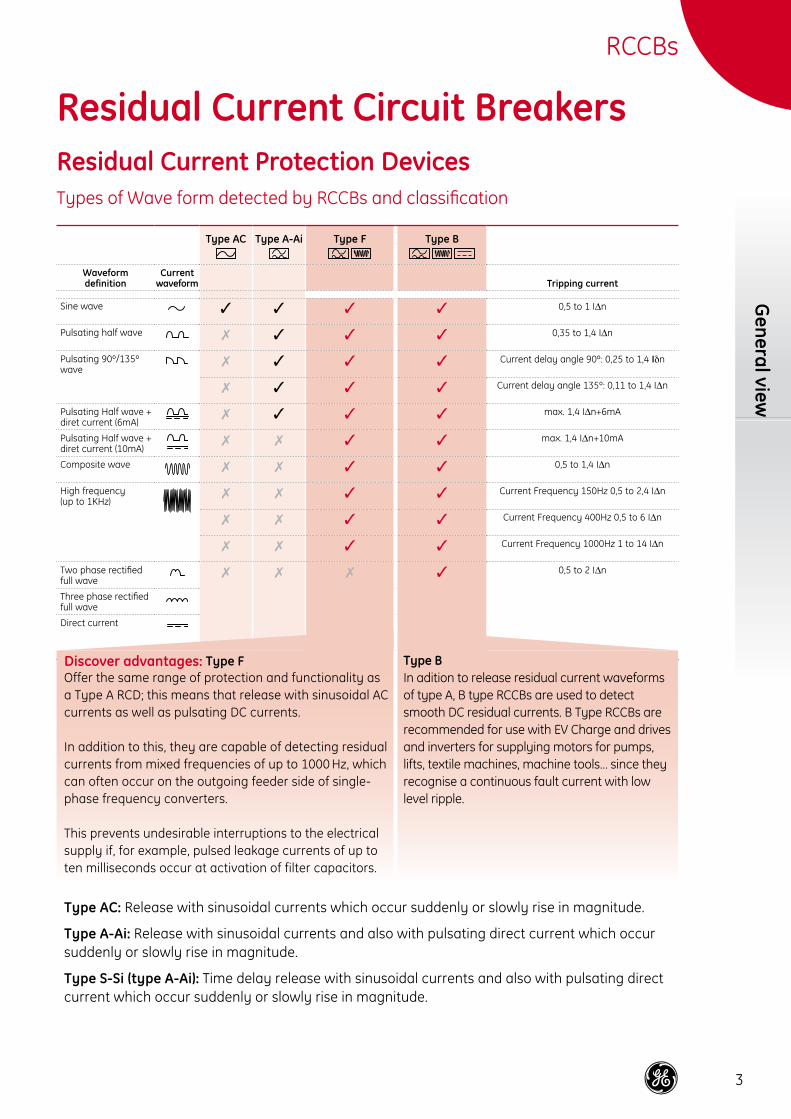
Type AC Type A-Ai Type F Type B
Waveform definition
Currentwaveform Tripping current
Sine wave ✓ ✓ ✓ ✓ 0,5 to 1 IΔn
Pulsating half wave ✗ ✓ ✓ ✓ 0,35 to 1,4 IΔn
Pulsating 90º/135º wave
✗ ✓ ✓ ✓ Current delay angle 90º: 0,25 to 1,4 Iδn
✗ ✓ ✓ ✓ Current delay angle 135º: 0,11 to 1,4 IΔn
Pulsating Half wave + diret current (6mA)
✗ ✓ ✓ ✓ max. 1,4 IΔn+6mA
Pulsating Half wave + diret current (10mA)
✗ ✗ ✓ ✓ max. 1,4 IΔn+10mA
Composite wave ✗ ✗ ✓ ✓ 0,5 to 1,4 IΔn
High frequency (up to 1KHz)
✗ ✗ ✓ ✓ Current Frequency 150Hz 0,5 to 2,4 IΔn
✗ ✗ ✓ ✓ Current Frequency 400Hz 0,5 to 6 IΔn
✗ ✗ ✓ ✓ Current Frequency 1000Hz 1 to 14 IΔn
Two phase rectified full wave
✗ ✗ ✗ ✓ 0,5 to 2 IΔn
Three phase rectified full wave
Direct current
General view
Residual Current Circuit BreakersResidual Current Protection DevicesTypes of Wave form detected by RCCBs and classification
RCCBs
Discover advantages: Type FOffer the same range of protection and functionality as a Type A RCD; this means that release with sinusoidal AC currents as well as pulsating DC currents. In addition to this, they are capable of detecting residual currents from mixed frequencies of up to 1000 Hz, which can often occur on the outgoing feeder side of single-phase frequency converters. This prevents undesirable interruptions to the electrical supply if, for example, pulsed leakage currents of up to ten milliseconds occur at activation of filter capacitors.
Type BIn adition to release residual current waveforms of type A, B type RCCBs are used to detect smooth DC residual currents. B Type RCCBs are recommended for use with EV Charge and drives and inverters for supplying motors for pumps, lifts, textile machines, machine tools… since they recognise a continuous fault current with low level ripple.
Type AC: Release with sinusoidal currents which occur suddenly or slowly rise in magnitude.
Type A-Ai: Release with sinusoidal currents and also with pulsating direct current which occur suddenly or slowly rise in magnitude.
Type S-Si (type A-Ai): Time delay release with sinusoidal currents and also with pulsating direct current which occur suddenly or slowly rise in magnitude.
4
RCCB
with
ove
rcur
rent
pro
tect
ion
RCCBs
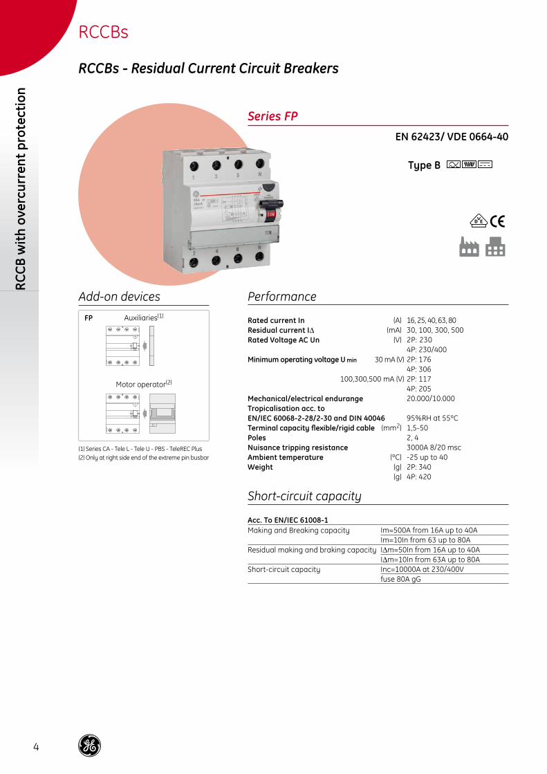
RCCBs - Residual Current Circuit Breakers
Series FPEN 62423/ VDE 0664-40
Type B
Performance
Rated current In (A) 16, 25, 40, 63, 80Residual current IΔ (mA) 30, 100, 300, 500Rated Voltage AC Un (V) 2P: 230
4P: 230/400Minimum operating voltage U min 30 mA (V) 2P: 176
4P: 306100,300,500 mA (V) 2P: 117
4P: 205Mechanical/electrical endurange 20.000/10.000Tropicalisation acc. toEN/IEC 60068-2-28/2-30 and DIN 40046 95%RH at 55ºCTerminal capacity flexible/rigid cable (mm2) 1,5-50Poles 2, 4Nuisance tripping resistance 3000A 8/20 mscAmbient temperature (ºC) -25 up to 40Weight (g) 2P: 340
(g) 4P: 420
Add-on devices
Auxiliaries(1)
Motor operator(2)
(1) Series CA - Tele L - Tele U - PBS - TeleREC Plus(2) Only at right side end of the extreme pin busbar
Short-circuit capacity
Acc. To EN/IEC 61008-1Making and Breaking capacity Im=500A from 16A up to 40A
Im=10In from 63 up to 80AResidual making and braking capacity IΔm=50In from 16A up to 40A
IΔm=10In from 63A up to 80AShort-circuit capacity Inc=10000A at 230/400V
fuse 80A gG
FP
5
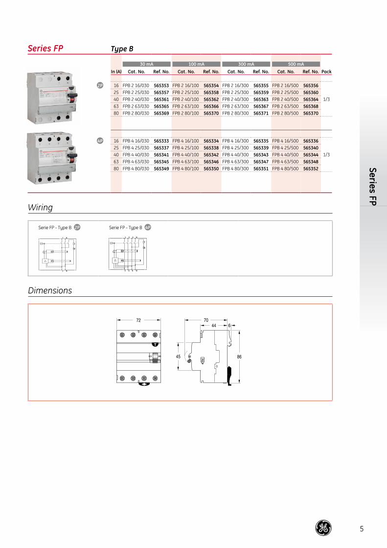
Series FP
Series FP Type B
30 mA 100 mA 300 mA 500 mAIn (A) Cat. No. Ref. No. Cat. No. Ref. No. Cat. No. Ref. No. Cat. No. Ref. No. Pack
16 FPB 2 16/030 565353 FPB 2 16/100 565354 FPB 2 16/300 565355 FPB 2 16/500 565356
1/325 FPB 2 25/030 565357 FPB 2 25/100 565358 FPB 2 25/300 565359 FPB 2 25/500 56536040 FPB 2 40/030 565361 FPB 2 40/100 565362 FPB 2 40/300 565363 FPB 2 40/500 56536463 FPB 2 63/030 565365 FPB 2 63/100 565366 FPB 2 63/300 565367 FPB 2 63/500 56536880 FPB 2 80/030 565369 FPB 2 80/100 565370 FPB 2 80/300 565371 FPB 2 80/500 565370
16 FPB 4 16/030 565333 FPB 4 16/100 565334 FPB 4 16/300 565335 FPB 4 16/500 565336
1/325 FPB 4 25/030 565337 FPB 4 25/100 565338 FPB 4 25/300 565339 FPB 4 25/500 56534040 FPB 4 40/030 565341 FPB 4 40/100 565342 FPB 4 40/300 565343 FPB 4 40/500 56534463 FPB 4 63/030 565345 FPB 4 63/100 565346 FPB 4 63/300 565347 FPB 4 63/500 56534880 FPB 4 80/030 565349 FPB 4 80/100 565350 FPB 4 80/300 565351 FPB 4 80/500 565352
Wiring
1 N
2 N
Serie FP - Type B
531 N
6 42 N
Serie FP - Type B
Dimensions
6
RCCB
with
ove
rcur
rent
pro
tect
ion
RCCBs
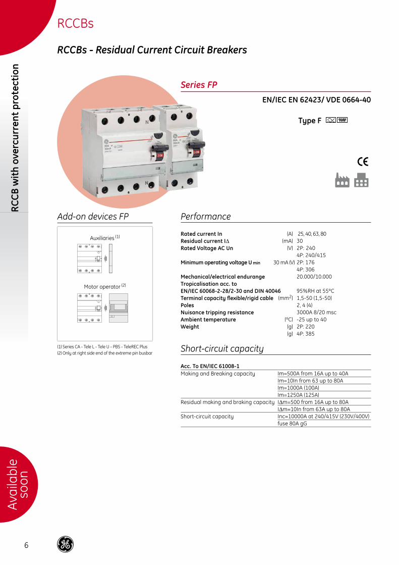
RCCBs - Residual Current Circuit Breakers
Series FPEN/IEC EN 62423/ VDE 0664-40
Type F
Performance
Rated current In (A) 25, 40, 63, 80Residual current IΔ (mA) 30Rated Voltage AC Un (V) 2P: 240
4P: 240/415Minimum operating voltage U min 30 mA (V) 2P: 176
4P: 306Mechanical/electrical endurange 20.000/10.000 Tropicalisation acc. toEN/IEC 60068-2-28/2-30 and DIN 40046 95%RH at 55ºCTerminal capacity flexible/rigid cable (mm2) 1,5-50 (1,5-50)Poles 2, 4 (4)Nuisance tripping resistance 3000A 8/20 mscAmbient temperature (ºC) -25 up to 40Weight (g) 2P: 220
(g) 4P: 385
Add-on devices FP
Auxiliaries (1)
Motor operator (2)
(1) Series CA - Tele L - Tele U - PBS - TeleREC Plus(2) Only at right side end of the extreme pin busbar
Short-circuit capacity
Acc. To EN/IEC 61008-1Making and Breaking capacity Im=500A from 16A up to 40A
Im=10In from 63 up to 80AIm=1000A (100A)Im=1250A (125A)
Residual making and braking capacity IΔm=500 from 16A up to 80AIΔm=10In from 63A up to 80A
Short-circuit capacity Inc=10000A at 240/415V (230V/400V)fuse 80A gG
Avai
labl
eso
on

7
Series FP
Series FP Type F
30 mAIn (A) Cat. No. Ref. No. Pack
25 FPF 2 25/030 565373
1/640 FPF 2 40/030 56537463 FPF 2 63/030 56537580 FPF 2 80/030 565376
25 FPF 4 25/030 565377
1/340 FPF 4 40/030 56537863 FPF 4 63/030 56537980 FPF 4 80/030 565380
Wiring
Serie FP - Type F
1
2
3
4
/2
/1
/4
/3
Serie FP - Type F
N
N
1
2
5
6
3
4
/2
/1
/6
/5
/4
/3
Dimensions
8
RCCB
with
ove
rcur
rent
pro
tect
ion
RCCBs
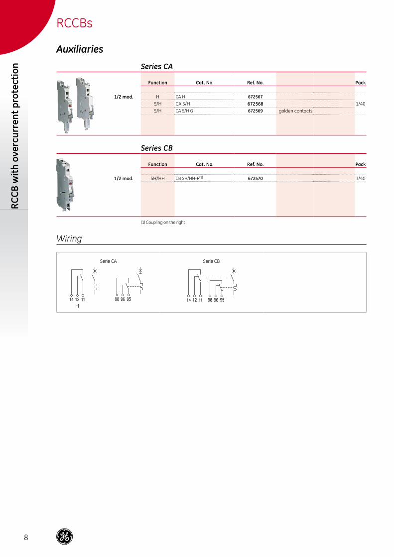
Series CA
Function Cat. No. Ref. No. Pack
1/2 mod. H CA H 6725671/40S/H CA S/H 672568
S/H CA S/H G 672569 golden contacts
Series CB
Function Cat. No. Ref. No. Pack
1/2 mod. SH/HH CB SH/HH-R(1) 672570 1/40
(1) Coupling on the right
Auxiliaries
Wiring
H
Serie CA Serie CB
9
Auxiliary - Add-on Devices
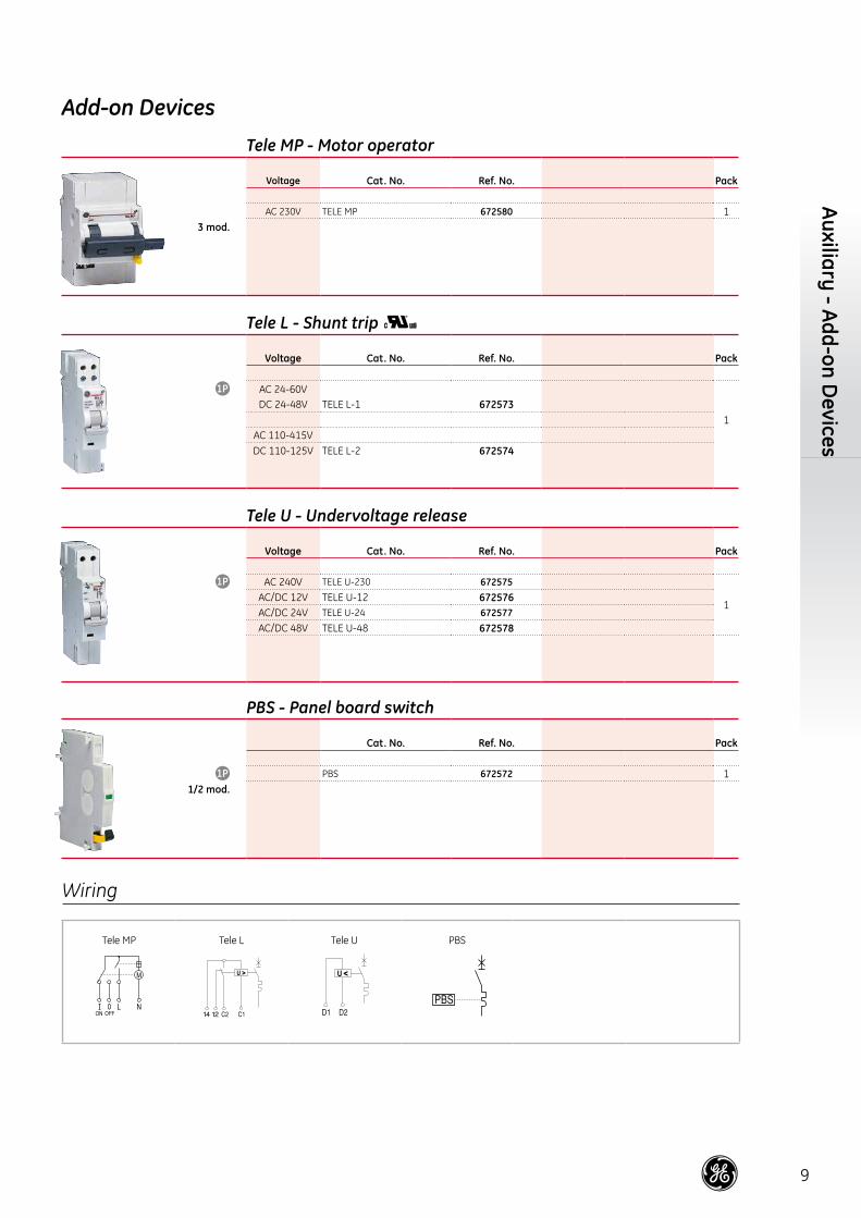
Tele L - Shunt trip
Voltage Cat. No. Ref. No. Pack
AC 24-60V
1
DC 24-48V TELE L-1 672573
AC 110-415VDC 110-125V TELE L-2 672574
Tele U - Undervoltage release
Voltage Cat. No. Ref. No. Pack
AC 240V TELE U-230 672575
1AC/DC 12V TELE U-12 672576AC/DC 24V TELE U-24 672577AC/DC 48V TELE U-48 672578
PBS - Panel board switch
Cat. No. Ref. No. Pack
PBS 672572 11/2 mod.
Tele MP - Motor operator
Voltage Cat. No. Ref. No. Pack
AC 230V TELE MP 672580 13 mod.
Add-on Devices
Wiring
Tele MP Tele L Tele U PBS
10
RCCB
with
ove
rcur
rent
pro
tect
ion
RCCBs
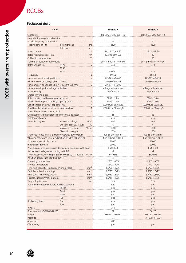
Technical dataSeries FP Type B FP Type F
Standards EN 62423/ VDE 0664-40 EN 62423/ VDE 0664-40Magnetic tripping characteristics - -Residual tripping characteristic B FTripping time at I Δn Instantaneous ms <300 <300 Selective ms - -Rated current A 16, 25, 40, 63, 80 25, 40, 63, 80
Rated residual current I Δn mA 30, 100, 300, 500 30
Calibration temperature ºC 30 30Number of poles versus modules 2P = 4 mod.; 4P = 4 mod. 2P = 2 mod.; 4P = 4 mod.Rated voltage Un 2P AC V 230 240 3P AC - 4P AC V 230/400 415Frequency Hz 50/60 50/60Maximum service voltage Ubmax V 2P=265/4P=460 2P=265/4P=455Minimum service voltage Ubmin (30 mA) V 2P=160/4P=258 2P=160/4P=258Minimum service voltage Ubmin (100, 300, 500 mA) V 2P=117/4P=205 -Minimum voltage for leakage protection Voltage independent Voltage independentPower supply Top/Bottom Top/BottomEnergy limiting class - -Rated making and breaking capacity (Im) A 500 (or 10In) 500 (or 10In)Residual making and breaking capacity (IΔ m) A 500 (or 10In) 500 (or 10In)Conditional short-circuit capacity (Inc) A 10000 fuse 80A gLgG 10000 fuse 80A gLgGConditional residual short-circuit capacity (IΔ c) A 10000 fuse 80A gLgG 10000 fuse 80A gLgGRated Short-circuit capacity (Icn) A - -Grid distance (safety distance between two devices) 35 35Isolator application yes yesInsulation degree Insulation voltage V(DC) 440 440 Shock voltage (1.2/50μs) kV 6 6 Insulation resistance Mohm 1000 1000 Dielectric strength V 2500 2500Shock resistance (in x, y, z direction) (EN/IEC 60077/16.3) 40g 18 shocks 5ms 40g 18 shocks 5msVibration resistance (in x, y, z direction) (EN/IEC 60068-2-6) 1,5g. 30 min, 0..80Hz 1,5g. 30 min, 0..80HzEndurance electrical at Un, In 10000 10000mechanical at Un, In 20000 20000Protection degree (outside/inside electrical enclosure with door) IP20/IP40 IP20/IP40Self extinguish degree (according to UL94) V2 V2Tropicalisation (according to EN/IEC 60068-2, DIN 40046) ºC/RH 55/95% 55/95%Pollution degree (acc. EN/IEC 60947-1) 3 3Operating temperature -25ºC…+40ºC -25ºC…+40ºCStorage temperature -25ºC…+70ºC -25ºC…+70ºCTerminals capacity Rigid cable min/max (top) mm2 1,5/50 (1,5/35) 1,5/50 (1,5/35)Flexible cable min/max (top) mm2 1,5/35 (1,5/25) 1,5/35 (1,5/25)Rigid cable min/max (bottom) mm2 1,5/50 (1,5/35) 1,5/50 (1,5/35)Flexible cable min/max (bottom) mm2 1,5/35 (1,5/25) 1,5/35 (1,5/25)Torque Top/Bottom Nm 5/5 5/5Add-on devices (side add-on) Auxiliary contacts yes yes Tele U yes yes Tele L yes yes Tele M yes yes PBS yes yesBusbars systems Pin yes yes Fork yes yes# Poles 2-4 2-4Dimensions (HxDxW) 86x70xW 72 36/72Weight 2P=340 ; 4P=420 2P=220 ; 4P=385Package 1/3 2P=1/6; 4P=1/3Approvals VDE -CE-marking yes yes


ge.com/ex/industrialsolutions
GEIndustrial Solutions
1153
15
GE Industrial Solutions is a first class global supplier of low and medium voltage products including wiring devices, residential and industrial electrical distribution components, automation products, enclosures and switchboards. Demand for the company’s products comes from wholesalers, installers, panelboard builders, contractors, OEMs and utilities worldwide.
680896Ref. R/2536/E/EX 1.0 Ed. 05/15
* Trademark of General Electric Company © Copyright GE Industrial Solutions 2015
BelgiumGE Industrial BelgiumNieuwevaart 51B-9000 GentTel. +32 (0)9 265 21 11
FinlandGE Industrial SolutionsKuortaneenkatu 2FI-00510 HelsinkiTel. +358 (0)10 394 3760
FranceGE Industrial SolutionsParis Nord 213, rue de la PerdrixF-95958 Roissy CDG CédexTel. +33 (0)800 912 816
GermanyGE Industrial SolutionsRobert-Bosch Str. 3D-50354 Hürth-EfferenTel. +49 (0) 2233/ 9719-0
HungaryGE Hungary Kft .Vaci ut 81-83.H-1139 BudapestTel. +36 1 447 6050
ItalyGE Industrial SolutionsCentro Direzionale ColleoniVia Paracelso 16Palazzo Andromeda B1I-20864 Agrate Brianza (MB)Tel. +39 039 637 371
NetherlandsGE Industrial SolutionsParallelweg 10Nl-7482 CA HaaksbergenTel. +31 (0)53 573 03 03
PolandGE Power ControlsUl. Towarowa 25A, Ip00-869 WarszawaTel. +48 22 520 53 53
Ul. Leszczyńska 643-300 Bielsko-Biała Tel. +48 33 828 62 33
RussiaGE Industrial Solutions27/8, Electrozavodskaya streetMoscow, 107023Tel. +7 495 937 11 11
South AfricaGE Industrial SolutionsUnit 4, 130 Gazelle AvenueCorporate Park Midrand 1685P.O. Box 76672 Wendywood 2144 Tel. +27 11 238 3000
SpainGE POWER CONTROLS IBÉRICA, S.L.Calle Miño 122 Naves E-FPolígono Industrial Santa Margarita08223 Terrassa (Barcelona)Tel. +34 900 993 625
United Arab EmiratesGE Industrial SolutionsInjaz Building, 3rd FloorDubai Internet CityPO Box 11549, DubaiTel. +971 4 4546912
United KingdomGE Industrial Solutions2 The Arena, Downshire WayBracknell, BerkshireRG12 1PUTel. +44 (0)800 587 1239