ge grid solutions kelman dga 900 installation manual · ma-024 – dga 900 installation manual –...
TRANSCRIPT

GEDE-GA_M-DLIS-TE.MA-024 Rev 1.0 21-Nov-17
GE Grid Solutions
Kelman™ DGA 900 Installation Manual
Transformer Oil Dissolved Gas and Moisture Monitor
MA-024 – DGA 900 Installation Manual – Rev 1.0 21-Nov-17 Page 2 of 69
Contents Topic Page 1 Introduction ......................................................................................................... 6
1.1 Product Overview ........................................................................................................................................................ 6 1.2 Scope ................................................................................................................................................................................ 8
2 Safety .................................................................................................................... 9 2.1 Symbols ........................................................................................................................................................................... 9 2.2 Safety Statements ...................................................................................................................................................... 9
3 Requirements ....................................................................................................11 3.1 Pre-installation ........................................................................................................................................................... 11 3.2 Handling & Storage .................................................................................................................................................. 11
4 Technical Specifications ..................................................................................13
5 Compliance ........................................................................................................15
6 Transformer Criteria ........................................................................................16
7 Mounting ............................................................................................................17
8 Plumbing.............................................................................................................19 8.1 Transformer Valves .................................................................................................................................................. 20 8.2 Supply & Return Valves .......................................................................................................................................... 21 8.3 Tubing ............................................................................................................................................................................. 22
9 Power ..................................................................................................................29 9.1 PCC cable ...................................................................................................................................................................... 31 9.2 Safety Earth ................................................................................................................................................................. 31 9.3 AC Power ....................................................................................................................................................................... 32 9.4 DC Power ....................................................................................................................................................................... 33 9.5 DC Distribution ........................................................................................................................................................... 34
10 Electronics ..........................................................................................................35 10.1 Controller PCB ............................................................................................................................................................. 35 10.2 I/O PCB ........................................................................................................................................................................... 36 10.3 Battery ............................................................................................................................................................................ 37
11 Relays & Inputs ..................................................................................................38 11.1 Connections ................................................................................................................................................................. 38 11.2 Relays .............................................................................................................................................................................. 39 11.3 Analogue and Digital Inputs ................................................................................................................................ 41
12 Communications ...............................................................................................45 12.1 Configuration .............................................................................................................................................................. 45 12.2 RS-485 ............................................................................................................................................................................ 47 12.3 DNP3 ............................................................................................................................................................................... 48 12.4 Modbus .......................................................................................................................................................................... 48
Appendix A Installation Tools and Supplies ..................................................49 GE-supplied Items ..................................................................................................................................................... 49 Customer-supplied Items ...................................................................................................................................... 49
Appendix B Customer Checklist.......................................................................51
Appendix C Installation Record .......................................................................52 Customer Contact and Site Details .................................................................................................................. 52 Transformer Details ................................................................................................................................................. 53 Pre-Installation Photographs .............................................................................................................................. 53
Appendix D Tubing Specification and Ordering Details ..............................55 Specifications .............................................................................................................................................................. 55 Order Information (E.g. Swagelok) .................................................................................................................... 55

MA-024 – DGA 900 Installation Manual – Rev 1.0 21-Nov-17 Page 3 of 69
Tubing Unions ............................................................................................................................................................. 55 Shut-Off Valve ............................................................................................................................................................. 55 6 mm Tubing Adaptors ........................................................................................................................................... 55 Tubing Material .......................................................................................................................................................... 56
Appendix E Product Dimensions .....................................................................58
Appendix F Mounting Stand Dimensions & Assembly .................................64
Appendix G Heat Trace Cable ...........................................................................68 Installation Requirements ..................................................................................................................................... 68
Contact & Copyright Details .................................................................................69

MA-024 – DGA 900 Installation Manual – Rev 1.0 21-Nov-17 Page 4 of 69
List of Tables and Figures Item Page Figure 1-1: Inside the DGA 900 ................................................................................................................................................ 6 Table 4-1: Measurements ........................................................................................................................................................ 13 Table 5-1: Type tests .................................................................................................................................................................. 15 Figure 8-1: Schematic representation of an installation .......................................................................................... 19 Figure 8-2: Examples of possible line configurations................................................................................................. 19 Figure 8-3: Transformer valve locations ........................................................................................................................... 20 Figure 8-4: Analysis module – bottom plate connections ....................................................................................... 24 Figure 8-5: Fitting body and tubing .................................................................................................................................... 25 Figure 8-6: Nut at 6 o'clock position ................................................................................................................................... 25 Figure 8-7: Nut at 9 o'clock position ................................................................................................................................... 25 Figure 8-8: Bleed assembly on flange-type oil return valve ................................................................................... 26 Figure 8-9: Flange example .................................................................................................................................................... 27 Figure 8-10: Return assembly installation kit ................................................................................................................. 27 Figure 8-11: Return assembly on a horizontal oil return valve ............................................................................. 28 Figure 9-1: Hub module — bottom plate connections .............................................................................................. 30 Figure 9-2: PCC cable ................................................................................................................................................................. 31 Figure 9-3: Safety Earth ............................................................................................................................................................ 31 Figure 9-4: Location of mains supply ................................................................................................................................. 32 Figure 9-5: Location of mains supply ................................................................................................................................. 33 Figure 9-6: DC block ................................................................................................................................................................... 34 Figure 9-7: DC block fitted ....................................................................................................................................................... 34 Figure 10-1: Controller PCB faceplate ............................................................................................................................... 35 Table 10-1: Other Controller PCB features ...................................................................................................................... 35 Figure 10-2: I/O PCB faceplate .............................................................................................................................................. 36 Figure 10-3: Controller PCB coin cell battery ................................................................................................................. 37 Figure 10-4: Marshalling board coin cell battery ......................................................................................................... 37 Figure 11-1: DGA 900 Connections ..................................................................................................................................... 38 Figure 11-2: Relay configuration .......................................................................................................................................... 39 Table 11-1: Relay cable sizes ................................................................................................................................................. 39 Figure 11-3: Terminal and power connections with WDG....................................................................................... 40 Figure 11-4: Analogue customer terminals .................................................................................................................... 41 Figure 11-5: Digital customer terminals ........................................................................................................................... 41 Table 11-2: Cable sizes .............................................................................................................................................................. 42 Figure 11-6: I/O faceplate label ............................................................................................................................................ 42 Figure 11-7: RTD 2-wire ............................................................................................................................................................ 43 Figure 11-8: RTD 3-wire ............................................................................................................................................................ 43 Figure 11-9: 4-20 mA ................................................................................................................................................................. 43 Table 12-1: Product communications channels ........................................................................................................... 45 Figure 12-1 Local HMI and Remote HMI: Communication Settings.................................................................... 45 Figure 12-2: Ethernet configuration ................................................................................................................................... 46 Figure 12-3: USB configuration ............................................................................................................................................. 46 Figure 12-4: GSM/GPRS configuration............................................................................................................................... 46 Figure 12-5: RS-485 connections ......................................................................................................................................... 47 Table 12-2: RS-485 terminal connections ....................................................................................................................... 47 Figure 12-6: RS-485 configuration ...................................................................................................................................... 47 Figure E-1: Analysis & Hub modules ................................................................................................................................... 58 Figure E-2: Analysis module – front dimensions........................................................................................................... 58 Figure E-3: Analysis module – side dimensions ............................................................................................................ 59 Figure E-4: Analysis module – bottom dimensions ..................................................................................................... 60 Figure E-5: Hub module – front dimensions ................................................................................................................... 61 Figure E-6: Hub module – side dimensions ..................................................................................................................... 62

MA-024 – DGA 900 Installation Manual – Rev 1.0 21-Nov-17 Page 5 of 69
Figure E-7: Hub module – bottom dimensions .............................................................................................................. 63 Figure F-1: Mounting stand – Analysis & Hub modules ............................................................................................ 64 Figure F-2: Mounting stand dimensions – front ............................................................................................................ 65 Figure F-3: Mounting stand – bottom view & footprint ............................................................................................. 66 Figure F-4: Mounting stand parts ........................................................................................................................................ 67 Table F-1: Mounting stand parts list ................................................................................................................................... 67
Related Documents Ref# Title
MA-025 DGA 900 Operator Guide
Abbreviations & Definitions Abbreviation Meaning
HMI Human Machine Interface
Controller PCB Controller Printed Circuit Board
I/O PCB Input / Output Printed Circuit Board
PPE Personal Protective Equipment
PCC Power, Communications and Control (cable)

MA-024 – DGA 900 Installation Manual – Rev 1.0 21-Nov-17 Page 6 of 69
1 INTRODUCTION
1.1 Product Overview
The Kelman™ DGA 900 (the product) is a multigas online DGA (Dissolved Gas Analysis)
and moisture monitoring system for implementing Asset Performance Management
(APM) across electrical generation, transmission, distribution and industrial applications.
The product as shown in Figure 1-1 can detect and diagnose incipient faults and trend
asset health via the monitoring of critical gases including moisture in the transformer oil.
This includes any mineral oil or ester-based fluid (natural or synthetic). The product
measures nine certified fault gases: hydrogen, methane, ethane, ethylene, carbon
monoxide, carbon dioxide, acetylene, oxygen, nitrogen as well as water content and the
transformer load current. Such data provides insight on transformer condition criteria,
such as developing faults, paper degradation and electrical arcing.
Once installed, operation is straightforward. The product can be managed remotely over
a network via a web-based interface or locally via a touchscreen interface. All results
are stored within the product, but online management is recommended. Results and the
full product database can also be downloaded to a PC for analysis, aggregation and
trending with the Perception software suite.
Figure 1-1: Inside the DGA 900
The product features:
▪ An innovative two-enclosure design connected by a Power, Communications and Control (PCC) cable for a more flexible installation configuration. The Analysis module contains the PGA measurement technology, whereas the Hub module contains the communications technology and LCD screen. The modules have IP56-rated aluminium*1 enclosures (compliant in the installed upright position) and are powder coated to the RAL 9002 specification.
▪ Automated headspace gas extraction manifold to extract target gases from the oil sample.

MA-024 – DGA 900 Installation Manual – Rev 1.0 21-Nov-17 Page 7 of 69
▪ Advanced high precision Photo-Acoustic Spectroscopy (PAS) sensing technology based on a robust multi-point individual gas calibration process using certified gases to calibrate the PGA (Photoacoustic Gas Analyser).
▪ Complete multi-gas analysis (nine gases and moisture) with a user-configurable sampling frequency from once per hour to once every four weeks including remote alert capabilities. All gas sensing is carried out internally without a need for carrier gases or recalibration. Minimal maintenance*2 and no requirement for costly consumables.
▪ A new ‘Rapid Mode’ allows sampling to be completed in around 30 minutes using five key gases and is useful in critical situations to give immediate insight on fast-developing faults.
▪ Improved lower detection limits and measurement repeatability for earlier detection of imminent faults on the transformer being monitored.
▪ Transformer load tracking (CT analogue input as standard).
▪ Watchdog relay as standard.
▪ Six configurable relay contacts based on absolute gas and moisture values (with one dedicated service).
▪ Five optional configurable analogue input cards.
▪ Three digital inputs (optional configurations available).
▪ Compatible with AC or DC power.
▪ Four sunlight-visible LED arrays on the exterior of the Hub module — red for alarm, yellow for caution (both user-configurable) — and green for power, blue for service.
▪ The product features a fully embedded microprocessor with 4 GB non-volatile internal memory storage, highly scalable analogue and digital I/Os, an embedded webserver, 8 GB SD card to hold measurement data and an integrated 7 in. colour LCD screen with resistive touch for simplified local user interaction and visualization of data.
▪ Enhanced and integrated computing power provides a platform for expansion and future feature enhancements complemented by an extensive range of secure communications options. These include Ethernet, RS-485, cellular modem (SMS Text Alerts /GPRS), and fibre optic options (IEC61850 or DNP3). Internal USB connection is provided for commissioning and service, or local data download. Other options may be available on request.
▪ Compatibility with GE’s Perception transformer fleet management software for data download, trending and analysis as well as other SCADA systems. The product is a DS-Agile and Predix-Grid APM ready device with support for industry standard protocols.
*1 Note: The product can also be ordered in Type 316 stainless steel (module and mounting stand). This offers superior resistance to corrosive salts and other chemicals, making it suitable for harsh environments, such as coastal areas and anywhere where there is a likelihood of exposure to chloride (e.g. where de-icing salts may be used).
*2 Note: The only recommended maintenance is periodic cleaning of the air filters, in-line oil filter and battery replacement.
MA-024 – DGA 900 Installation Manual – Rev 1.0 21-Nov-17 Page 8 of 69
1.2 Scope
This manual details the installation requirements and procedure, including important
pre-installation tasks to be considered when planning and preparing for the installation.
It examines mounting, plumbing, power, electronics and communications — including
tools, supplies and items to purchase. Operational details can be found in the product
operator guide. This manual must be read in its entirety prior to installation to prepare
the site and obtain the necessary equipment. Refer to the appendices for details and
record site details in the Installation Record (see Appendix C).

MA-024 – DGA 900 Installation Manual – Rev 1.0 21-Nov-17 Page 9 of 69
2 SAFETY
2.1 Symbols
The meaning of symbols used on the Kelman™ DGA 900:
Refer to the Installation Manual / Operator Guide to prevent death, injury, equipment damage or loss of data.
Electrical Hazard. Risk of electric shock.
Primary Protective Earth connection.
Hot surfaces may be present.
The meaning of symbols used in this manual:
Warning: A procedure, practice, or condition could cause death or serious injury and/or significant equipment damage.
[Caution]: A procedure, practice, or condition could cause minor injury, equipment damage or loss of data.
Electrical Hazard: Risk of electric shock.
Hot surfaces may be present.
2.2 Safety Statements
The following safety statements must be observed:
The customer and installer are responsible for ensuring that all local regulations and site policies are complied with in regards to safe working practices.
Installation and service activities are not recommended in ambient temperatures below −10 °C.
The customer and installer are responsible for ensuring that all local regulations and site policies are complied with in regards to safe working practices.

MA-024 – DGA 900 Installation Manual – Rev 1.0 21-Nov-17 Page 10 of 69
If the equipment is installed or used in a manner not specified by the manufacturer, the protection provided by the equipment may be impaired.
If working at height, third parties must have received appropriate training for working at height prior to work commencing. This includes, but is not limited to, ‘Working at height’ and ‘Using Mobile Elevated Working Platforms’ training.
If working at a height greater than 4 feet (1.2 metres) or at a height greater than that stipulated by national or site regulatory requirements, it is the responsibility of the installer to ensure that planned work complies with those requirements.
The installer shall also ensure that any third-party equipment, such as an approved platform, scaffold or lift is suitable and safe before commencing work. Ladders or improvised platforms do not meet GE service engineer requirements.
Hot surfaces present on oil pipes and risk of contact with mineral oil. Use suitable PPE.
Once installed, this product may have more than one source of electrical supply. Disconnect all supplies at their source before accessing the cabinet for servicing. Follow the site lockout-tagout (LOTO) procedure.
Only GE-trained and certified personnel may commission GE Kelman products. Commissioning tasks include making any connections and/or performing any work within the module, or performing tasks such as purging the oil circuit between the transformer and the product, and/or all first start-up procedures relating to equipment or firmware/software.

MA-024 – DGA 900 Installation Manual – Rev 1.0 21-Nov-17 Page 11 of 69
3 REQUIREMENTS
3.1 Pre-installation
To ensure success, careful planning and proper execution of the tasks outlined in this
manual are essential. The regional GE Service Manager will need specific information to
provide recommendations for a trouble-free installation. If GE is to perform the
installation, the installation will not be scheduled until all pre-installation tasks outlined
in this manual are complete (as performed by the customer and GE).
The product can be safely connected to an energised or non-energised transformer.
If installation personnel are required to work in an energised environment they must be made aware of this prior to work commencing and must observe all health and safety practices, especially when working with conductive materials such as stainless steel installation tubing.
If either of the oil supply or return valves to be utilised brings personnel within restricted approach boundaries, then the transformer must be de-energised, isolated and grounded before such work is performed.
The appendices to this manual contain additional information, such as drawings, forms
and checklists that need to be reviewed and completed prior to the installation. This
relates to materials and facilities that need to be ordered, acquired and in place well in
advance of the scheduled installation date. Confirmation of this needs to reach GE as
soon as possible, recommended four weeks prior to the installation date, unless prior
arrangements have been made with the installation group. This aids in planning and
supporting the installation thereby ensuring a trouble-free commissioning process.
3.2 Handling & Storage
The product is shipped in a wooden crate that is bolted to a pallet. Each module is
placed in a cardboard carton with foam pieces, sealed and wrapped in a plastic liner.
The modules are boxed separately, but placed in the crate together. The pallets can be
stacked to a maximum of three high.
It is important to take precautions prior to lifting (see Section 4 Technical Specifications for product weight details). The product shall be lifted into position using sufficient personnel or mechanical means in accordance with local regulations and company policies. The product must be lifted by the main module casing — not by the door or fan as that could damage the product. Any weight more than 25 kg requires a multi-person lift.
For short-term storage (defined as less than one week), it is acceptable to store the
product in the open air, provided it is protected from wet weather and direct sunlight by
a suitable customer-supplied waterproof covering and that the outside temperature
does not exceed 45 °C or fall below 0 °C. For storage periods exceeding one week,
customers are requested to store the product in a fully enclosed building that is free
from damp and extremes in ambient temperature. The storage facility temperature
should be between 2 °C and 30 °C.

MA-024 – DGA 900 Installation Manual – Rev 1.0 21-Nov-17 Page 12 of 69
Note: Customers are fully responsible for ensuring that stacked pallets are stable and, if necessary, providing additional external support. Damage incurred by improper customer handling or storage will not be covered under warranty.

MA-024 – DGA 900 Installation Manual – Rev 1.0 21-Nov-17 Page 13 of 69
4 TECHNICAL SPECIFICATIONS
The product meets the following technical specification as outlined in Table 4-1.
Table 4-1: Measurements
PARAMETER VALUE/MEETS
GAS MEASURED *1 & 10 RANGE ACCURACY *2 & 3 REPEATABILITY *2
Hydrogen (H2) 5 – 5,000 ppm ± 5% or ± LDL <3%
Methane (CH4) 2 – 50,000 ppm ± 3% or ± LD L <2%
Ethane (C2H6) 1 – 50,000 ppm ± 3% or ± LDL <2%
Ethylene (C2H4) 1 – 50,000 ppm ± 3% or ± LDL <2%
Acetylene (C2H2) 0.5 – 50,000 ppm ± 3% or ± LDL <2%
Carbon Monoxide (CO) 1 – 50,000 ppm ± 3% or ± LDL <2%
Carbon Dioxide (CO2) 20 – 50,000 ppm ± 3% or ± LDL <3%
Oxygen (O2) 100 – 50,000 ppm ± 5% or ± LDL <3%
Nitrogen (N2) *4 10,000 – 100,000 ppm ± 15% or ± LDL <3%
Moisture (H2O) 0 – 100% Relative Saturation *5
± 3.5% <3%
Measurement frequency Variable – Once per hour to once every 4 weeks
ENVIRONMENTAL Operating external temperature range
−40 °C to 55 °C
Storage temperature range 0 °C to 45 °C
Oil temperature range *6 −20 °C to 120 °C
Altitude Up to 2000 m
Atmospheric pressure Up to 1050 mbar
Operating humidity 10 – 95% RH non-condensing
Enclosure IP56
Weight *7 Analysis module: 33.4 kg (73.6 lb)
Hub module: 18.5 kg (40.8 lb)
2 m PCC cable: 0.8 kg (1.83 lb)
Product weight: 52.7 kg (116.3 lb)
POWER REQUIREMENTS Nominal input voltage range:
100-250 V DC 4 A
100-240 V AC, 50/60 Hz, 4 A
Input voltage range:
90-264 V AC
90-275 V DC
AC frequency range:
45-65 Hz
Single phase Alarm Relays: NO and NC provided
10 A 250 V AC, 10 A 30 V DC, 0.3 A 110 V DC, 0.12 A 220 V DC
Fuses *9 10 A 600 V AC/DC EATON KLM-10
Coin cells Panasonic CR2450 3 V 620 mAh
*1 Note: Parameters specified in application with mineral oil.
*2 Note: Accuracy and repeatability are quoted for the detectors under factory calibration and test levels. Gas-in-oil measurements may be affected by sampling and/or oil type.

MA-024 – DGA 900 Installation Manual – Rev 1.0 21-Nov-17 Page 14 of 69
*3 Note: Whichever is greater.
*4 Note: Available on free-breathing transformers only.
*5 Note: Given in ppm.
*6 Note: Based on testing carried out using VOLTESSO™ 35 mineral oil over a ¼ in. pipe run of 10 metres or less from oil supply or return valve to product connection point, and on transformer oil supply valve volumes of 200 ml or less. For oil temperatures colder than −20 ºC, GE recommends the use of heat trace cabling on piping. Low oil viscosity reduces oil flow.
*7 Note: The weight depends on the order specification. The stated weight is for a base product without packaging and excludes options such as a mounting stand. Check the shipping document for the exact packaged weight.
*8 Note: Maximum DC breaking capacity for a resistive load.
*9 Note: Use only the approved and recommended fuse to ensure continued fire protection and compliance.
*10 Note: Laboratory results can vary greatly worldwide as has been established through many round-robin tests. Any comparison of DGA 900 measurement results against laboratory results need to be considered in this context.

MA-024 – DGA 900 Installation Manual – Rev 1.0 21-Nov-17 Page 15 of 69
5 COMPLIANCE
The product is designed to meet the following type tests as listed in Table 5-1.
Table 5-1: Type tests
CATEGORY STANDARD CLASS/LEVEL TEST
EMC Emissions EN 61326-1:2006
CISPR 11 A Radiated & Conducted Emissions
FCC Part 15 Meets the requirements of A
Radiated & Conducted Emissions
EN 61000-3-2 A Harmonic Current Emissions Limits
EMC Immunity EN 61326-1:2006
IEC 61000-6-5: 2015
EN 61000-4-2 IV Electrostatic Discharge
EN 61000-4-3 III Electromagnetic Field Immunity
EN 61000-4-4 III Electrical Fast Transients
EN 61000-4-5 III Surge Immunity
EN 61000-4-6 III Conducted RF Immunity
EN 61000-4-8 IV & V Magnetic Field Immunity
EN 61000-4-11 III Voltage Dips & Interruptions
IEC 61000-4-12 2.5 kV & 1 kV Oscillatory Wave
IEC 61000-4-16 A Mains frequency voltage
EN 60255-5 5 kV, 2 kV & 500 V DC
Impulse, Dielectric & Insulation resistance testing
Environmental Tests
IEC 60068-2-1 −40 °C Cold
IEC 60068-2-2 55 °C Dry Heat
IEC 60068-2-6 10 – 500 Hz, 0.5 g operation
10 – 500 Hz, 1 g endurance
Vibration
IEC 60068-2-30 55 °C, 95% RH Damp Heat
EN 60529 IP56 Degree of Protection
Safety IEC 61010-1 2010
EN 61010-1 2010
MA-024 – DGA 900 Installation Manual – Rev 1.0 21-Nov-17 Page 16 of 69
6 TRANSFORMER CRITERIA
The transformer shall meet the following criteria:
▪ The transformer contains mineral type oils (paraffinic or naphthenic) that meet the requirements of IEC 60296, BS EN 60296, VDE 0370 or ASTM D 3487.
▪ The transformer oil must be certified PCB free.
▪ The temperature of the oil at the outlet valve of the transformer should not fall below −20 °C nor exceed 120 °C.
▪ The transformer oil is at atmospheric pressure or above (see points below).
▪ There are separate supply and return valves available for connection.
▪ The condition of the transformer supply and return valves must allow a secure long-term connection to the product. The valve size should measure at least 15 mm (½ in.) in diameter.
▪ The ambient temperature in the area where the product resides should not fall below −40 °C nor exceed 55 °C.
If the transformer is nitrogen blanketed, check the pressure/vacuum gauge. If the
pressure is positive, then the product can be installed.
Warning: Do not install the product on an energised transformer that is under vacuum. If the pressure is negative, a vacuum exists within the transformer. Air will be drawn into the transformer when a valve is opened. Air bubbles could be damaging to the transformer if the transformer is energised.
Dielectric fittings are a safety measure to prevent circulating currents from flowing in the tubing circuits whenever a transformer is not grounded to the same point as the monitoring product. Customers should consult with their local tubing supplier to source suitable dielectric fittings if required.

MA-024 – DGA 900 Installation Manual – Rev 1.0 21-Nov-17 Page 17 of 69
7 MOUNTING
Depending on requirements and the installation environment, each module can be
mounted on a separate standalone mounting stand (recommended) or direct mounted
to the body of a transformer. The two-module approach allows for a variety of mounting
arrangements, such as side-by-side, back-to-back or split.
When considering where and how to mount the product, observe the following points to ensure an appropriate mounting arrangement:
▪ The product shall be lifted into position using sufficient personnel or mechanical means in accordance with local regulations and company policies. See Section 4 Technical Specifications for product weight details.
▪ The product must be lifted by the main module casing — not by the door or fan, as this could damage the product.
▪ A PCC cable for power and communications links both modules. The standard length is 2 metres, but can be ordered in 5 metre or 10 metre lengths depending on the mounting arrangement. The cable must be routed and secured between the modules so that it cannot be stepped on, tripped over or damaged by activities in the area during normal operation, maintenance of nearby equipment or during evacuations.
▪ A split arrangement allows the Analysis and Hub modules to be located apart (subject to the current maximum cable length). This arrangement allows the Analysis module to be positioned close to the transformer, and the Hub module (containing the LCD screen) to be positioned at a more convenient distance for operation.
▪ The location for the Analysis module shall allow easy access to the transformer oil supply and return valves, so that tubing runs can be kept to a minimum, particularly in case of extreme temperature. The supply and return tubing runs between each transformer valve and the product connection point should not exceed 30 m (98 ft) in length, or 60 m (196 ft) in total length for the complete oil circuit. Note: This avoids putting stress on the internal pump and reduces the possibility of oil cavitation.
▪ If the recommended GE mounting stands are not purchased, structurally sound weather-resistant mountings that support the weight of the respective modules must be available (see Appendix F for dimensions). It must also be designed to be securely fastened to a flat mounting surface. Additional reinforcement and/or dampening may be necessary if local conditions (environmental or otherwise) could expose the product to potential external forces or vibration.
▪ The product must be mounted on a flat surface within 5 degrees of plumb and level on both axes, and the surface must support the combined weight of the module and its mounting stand. (See Appendix F).
▪ The product shall be bolted to the surface using three M8 threaded fasteners per leg of a recommended minimum length of 80 mm.
▪ If a new concrete foundation is required, the size of the concrete pad for each module should measure – at least 61 cm (24 in.) wide by 122 cm (48 in.) long and 9 cm (3 ½ in.) thick with a #3 (10 mm) steel reinforcing bar around the perimeter (earth bonded as per local or site practice and code). Depending on the installation arrangement, the size of the concrete pad may need to be doubled to
MA-024 – DGA 900 Installation Manual – Rev 1.0 21-Nov-17 Page 18 of 69
accommodate two modules or a second one reproduced at the location of the other module.
▪ The product must not be mounted where it could interfere with the regular maintenance of the transformer.
▪ The product must not be mounted where it could interfere with the airflow of the transformer’s cooling system.
▪ At least 100 cm (3.3 ft) must be kept clear of the Peltier cooler. The airflow to the vent areas on the bottom and sides of the product must not be blocked or restricted in any way. See Appendix E.
▪ At least 75 cm (2.5 ft) must be kept clear directly in front of each module. The front door of each module opens for access during installation, maintenance or operation.
▪ It is acceptable to mount the product to the body of a transformer that is exhibiting normal operational levels of vibration, if
➢ care is taken to ensure a level and secure mounting arrangement;
➢ the product is mounted within 5 degrees of plumb and level on both axes;
➢ the product is mounted in such a way as to support the total weight of the
product;
➢ the product is mounted at a height that is accessible from ground level without
ladders or platforms for operation and service purposes;
➢ the product is mounted to an area of the tank body with minimum vibration,
such as close to a corner or the stiffeners;
➢ guidance on inlet and outlet oil supply lengths and configuration is followed.
▪ If there is concern about vibration on a transformer, GE strongly advises against mounting the product to the body of a transformer. Furthermore, should damage occur to the product that is attributable to the mounting arrangement and/or excessive transformer vibration, such damage will not be covered under warranty. Care should always be taken to ensure that damage does not occur to the transformer or the product during installation or operation.
▪ The chosen location should take account of the potential requirement for testing an onsite water deluge system (if applicable), such that the product is not located in the direct line of water jets. While the product provides IP56-rated water spray protection, a water deluge system could exceed IP56 thresholds depending on the location, pressure and direction of the water jets. See the DGA 900 Operator Guide for further recommendations around testing a water deluge system.

MA-024 – DGA 900 Installation Manual – Rev 1.0 21-Nov-17 Page 19 of 69
8 PLUMBING
The product draws oil from the transformer, extracts the gases, analyses the gases and
then returns the oil to the transformer. The locations from which the oil is supplied and
returned are important for the accurate analysis of the gases (see Figure 8-1 and Figure
8-2).
Figure 8-1: Schematic representation of an installation
The oil is supplied from one valve of the transformer (the supply valve) and returned via
another (the return valve). The location of the supply valve should produce an oil sample
that is a well-mixed representation of the transformer oil. The following pages contain
points to consider when choosing where to connect the oil circuit from the transformer
to the product.
Figure 8-2: Examples of possible line configurations

MA-024 – DGA 900 Installation Manual – Rev 1.0 21-Nov-17 Page 20 of 69
8.1 Transformer Valves
The possible valve locations of a transformer are shown in Figure 8-3.
Figure 8-3: Transformer valve locations
8.1.1 Fill Valve
If the transformer is nitrogen blanketed, the fill valve or any other valve at the top of the
transformer should not be used as an oil supply valve because there is no guarantee
that there will always be oil at this position. However, it is acceptable to return oil
through this valve.
8.1.2 Drain Valve
The drain valve may be used as an oil supply or oil return valve. However, it is
particularly useful to return the oil to the transformer through this valve because it is
near ground level, providing an easily accessible point to bleed the air from the oil lines
during product commissioning.
8.1.3 Ancillary Valves
Some transformers have an array of ancillary valves and ports. These valves can be a
good choice to connect the product to the transformer, although it is important to know
how these valves route inside the transformer.
Ensure that the valve chosen to return oil is not internally piped to another location within the transformer, such as the headspace or the internal windings.
MA-024 – DGA 900 Installation Manual – Rev 1.0 21-Nov-17 Page 21 of 69
8.1.4 Cooling Loop Valves
The product should only be supplied with oil from a cooling loop valve if there are no
other valves available. Note: If oil must be taken from an oil-forced cooling loop, the oil
supply valve must be located on the high-pressure side of the oil pump.
Do not return oil to the cooling loop unless the cooling is not directed flow and that there are no other alternative valves in which to connect the product.
8.2 Supply & Return Valves
All transformers have different valve configurations. The transformer supply and return
valves should be assessed for durability to ensure that a reliable connection can be
made. The valve size should measure at least 15 mm (½ in.) in diameter. These valves
will need to be adapted to ¼ in. female NPT fittings to properly fit the ¼ in. NPT male
fittings on the product. When choosing how to prepare the oil supply and return valves,
consider these points:
Hot surfaces present on oil pipes and risk of contact with mineral oil. Use suitable PPE.
8.2.1 Oil Supply
▪ Oil is typically taken from a valve midway up on the transformer or from an active cooling loop. Note: If oil must be taken from an oil-forced cooling loop, the oil supply valve must be located on the high-pressure side of the oil pump. It is necessary to ensure that the oil is taken from a location where the oil is well mixed and in the active flow of transformer oil. The oil temperature at this location should not exceed 120 °C or be lower than −20 °C.
▪ The distance between the oil supply valve and oil return valve should be at least 30 cm (12 in.) to prevent mixing of the de-gassed oil with the transformer oil being sampled.
▪ Fittings must be provided to adapt the oil supply valve to a ¼ in. female NPT fitting using fittings and adaptors made from stainless steel, brass or black iron.
Do not use galvanised steel, copper or plastic fittings as these materials can negatively affect the gas concentrations in the sample line.
▪ If the oil supply valve is located more than 1.82 m (6 ft) above the base of the transformer, it is recommended that an additional ¼ in. ball valve be placed in the oil supply line within easy reach while standing, and in an easily accessible and visible location. This valve can be used to conveniently shut off the oil supply, if required.
8.2.2 Oil Return
▪ Oil is typically returned to a valve lower on the transformer, such as the transformer drain valve.

MA-024 – DGA 900 Installation Manual – Rev 1.0 21-Nov-17 Page 22 of 69
Do not return the oil to a location that leads directly to a critical location within the transformer, such as a cooling loop designed for directed cooling.
▪ Oil returning to the transformer must be via the ‘return assembly’ provided in the product installation kit. This assembly incorporates a check valve, a ball valve and a port that facilitates bleeding the system of air during the installation process. The bleed port must be oriented up so that air can be drawn from it. The assembly can be reconfigured to fit the transformer valve and adaptor, but must first be adapted from a ¼ in. female NPT fitting.
▪ If the oil return valve is located more than 1.82 m (6 ft) above the base of the transformer, it is recommended that an additional ¼ in. ball valve be placed in the oil return line within easy reach while standing, and in an easily accessible and visible location. This valve can be used to conveniently shut off the oil return, if required.
▪ It is important to ensure that the configuration of the return assembly eliminates any pre-existing air pockets. This is achieved using a Tee on the return valve with the bleed port facing upwards. To reduce the possibility of air pockets behind the flange, the position of the ¼ in. NPT hole must be drilled near the top of the flange, offset from the centre (see Figure 8-9).
Note: An optional manual oil sampling arrangement can be fitted to the oil inlet on the base of the product. For more information, contact the GE Customer Service Centre.
8.3 Tubing
Stainless steel tubing is used to connect the product to the transformer. The amount of
tubing required is based on the location of the product in relation to the valves on the
transformer.
Stainless steel is the only material that should be used — the use of any other tubing material would invalidate the results of the analysis and void the warranty of the product. (See Appendix D for a full description of the tubing.)
It is also recommended that each section of tubing between the transformer and the
product be installed as one continuous piece, and to use as few fittings as possible to
reduce restriction and minimise the risk of oil leaks.
Consider these points when choosing where to route the tubing and estimating how
much tubing is required:
▪ The route must not interfere with the regular maintenance of the transformer. The tubing shall not be routed so that it could be stepped on, tripped over or damaged by activities near the transformer.
▪ The route shall be selected to allow the tubing to be secured to existing structures. It is important that the tubing be adequately secured to the structure of the transformer or ancillary structure with appropriate mounting hardware and fasteners. (Swagelok or Ham-Let offer several options for mounting and securing tubing.)

MA-024 – DGA 900 Installation Manual – Rev 1.0 21-Nov-17 Page 23 of 69
▪ When measuring the routes chosen for the tubing between the product and the transformer oil supply and return valves — corners, bends and other obstacles may add to the overall length and must be taken into consideration.
▪ The rigid tubing is typically supplied in 6 m (20 ft) lengths (see Appendix D). If the length of either tubing path exceeds 6 m (20 ft), ¼ in. stainless steel compression unions will need to be provided along with the additional tubing. The required amount of tubing, in accordance with the specification in Appendix D, must be on site on the day of the installation.
▪ Bending the rigid tubing is a complicated procedure and if there is a change to the proposed route during the installation it could require extra tubing. For this reason, it is advisable to order at least 20% more tubing than the initial required estimate.
▪ Flexible tubing is also available and can be ordered in custom lengths.
▪ If the supplied shut-off valves are mounted to transformer valves that are 1.82 m (6 ft) or more above the ground, an additional ¼ in. stainless steel compression ball valve should be installed on the ¼ in. tubing at an easy to reach and visible location. This valve should be located not more than 1.82 m (6 ft) above the ground. This will facilitate turning off the oil flow, if needed, without having to climb to reach the supply valve. One additional ¼ in. stainless steel compression ball valve is included in the product installation kit.
If the oil temperature can fall below −20 °C, a heat trace may be fitted to the oil pipe to increase the oil temperature before it enters the product. See Appendix G. Note: The heat trace will need to be powered externally and be installed in accordance with the manufacturer’s instructions and local wiring regulations.
8.3.1 Fitting Requirements
Figure 8-4 shows the bottom-plate connection points for the Analysis module. The
stainless-steel tubing should be fitted between the transformer and the module as
follows, ensuring that:
▪ The supply line is connected to the OIL IN port (this is the bulkhead fitting at the bottom of the Analysis module that is located closest to the right-hand-side when viewed from the front). This line will route to the transformer supply valve.
▪ The return line is connected to the OIL OUT port (this is the bulkhead fitting at the bottom of the product that is located closer to the left-hand side when viewed from the front). This line will route to the return assembly on the transformer valve.
▪ All stainless-steel tubing is clean and de-burred before attaching the tube fittings.
▪ All tubing is properly secured to the transformer or other suitable non-vibrating structures.
▪ All tube fittings are sufficiently tightened as per the fitting instructions below (also outlined in the relevant manufacturer’s documentation).

MA-024 – DGA 900 Installation Manual – Rev 1.0 21-Nov-17 Page 24 of 69
Figure 8-4: Analysis module – bottom plate connections
Ambient temperature sensor
PCC cable connection (to Hub) Oil-out port
Exhaust
Manual sampling port
Oil-in port
Earth stud (M8)
MA-024 – DGA 900 Installation Manual – Rev 1.0 21-Nov-17 Page 25 of 69
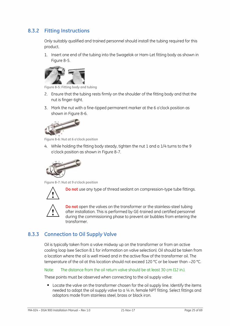
8.3.2 Fitting Instructions
Only suitably qualified and trained personnel should install the tubing required for this
product.
Insert one end of the tubing into the Swagelok or Ham-Let fitting body as shown in
Figure 8-5.
Figure 8-5: Fitting body and tubing
Ensure that the tubing rests firmly on the shoulder of the fitting body and that the
nut is finger-tight.
Mark the nut with a fine-tipped permanent marker at the 6 o’clock position as
shown in Figure 8-6.
Figure 8-6: Nut at 6 o'clock position
While holding the fitting body steady, tighten the nut 1 and a 1/4 turns to the 9
o’clock position as shown in Figure 8-7.
Figure 8-7: Nut at 9 o'clock position
Do not use any type of thread sealant on compression-type tube fittings.
Do not open the valves on the transformer or the stainless-steel tubing after installation. This is performed by GE-trained and certified personnel during the commissioning phase to prevent air bubbles from entering the transformer.
8.3.3 Connection to Oil Supply Valve
Oil is typically taken from a valve midway up on the transformer or from an active
cooling loop (see Section 8.1 for information on valve selection). Oil should be taken from
a location where the oil is well mixed and in the active flow of the transformer oil. The
temperature of the oil at this location should not exceed 120 °C or be lower than −20 °C.
Note: The distance from the oil return valve should be at least 30 cm (12 in.).
These points must be observed when connecting to the oil supply valve:
▪ Locate the valve on the transformer chosen for the oil supply line. Identify the items needed to adapt the oil supply valve to a ¼ in. female NPT fitting. Select fittings and adaptors made from stainless steel, brass or black iron.

MA-024 – DGA 900 Installation Manual – Rev 1.0 21-Nov-17 Page 26 of 69
Do not use galvanised steel, copper or plastic fittings as these materials can negatively affect the gas concentrations in the sample line.
▪ All pipe fittings should be tight and all tapered threaded pipe fittings tightly wrapped with PTFE tape with a light coating of PTFE paste or other quality pipe thread sealant applied over the taped male threads to prevent leaks. Both items are included in the product installation kit.
Note: Two wraps of PTFE tape are recommended (or three for large pipe fittings).
8.3.4 Connection to Oil Return Valve
Oil is typically returned to a valve lower on the transformer, such as the transformer
drain valve.
Note: The distance from the oil supply valve should be at least 30 cm (12 in.).
Do not return the oil into a high-pressure area on the transformer, such as a cooling loop.
The following points must be observed when connecting to the oil return valve (see
Section 8.1 for information on valve selection).
▪ The return line to the transformer must be via the return assembly (see Figure 8-8 to Figure 8-11). This assembly incorporates a check valve and port that facilitates bleeding the system of air during the commissioning process. The bleed port must be oriented vertically as the highest part of the commissioning assembly so that air can be drawn from the bleed port. The assembly can be reconfigured to fit the transformer valve and adaptor. This assembly must be adapted from a ¼ in. female NPT fitting to the valve on the transformer.
Figure 8-8: Bleed assembly on flange-type oil return valve
▪ If a flange-type valve is to be used to return the oil and the flange is drilled and tapped to a ¼ in. female NPT fitting, then the drilled hole should be offset to the top of the internal valve diameter to prevent an air pocket from being trapped behind the flange (see Figure 8-9).
Check Valve
Bleed Port (must be oriented vertically)

MA-024 – DGA 900 Installation Manual – Rev 1.0 21-Nov-17 Page 27 of 69
Figure 8-9: Flange example
Figure 8-10 depicts the return assembly from the installation kit.
Figure 8-10: Return assembly installation kit
▪ All pipe fittings should be tight, and all threaded pipe fittings tightly wrapped with PTFE tape and a light coating of PTFE paste or other quality pipe thread sealant applied over the taped male threads to prevent leaks. Both items are included in the product installation kit.
Note: Two wraps of PTFE tape are recommended (or three for large pipe fittings).
Bolt holes
Inside valve diameter behind the flange
¼ in. NPT return port
Check valve – the arrow must point toward the transformer.
Elbow is only used if the ¼ in. female NPT fitting face is vertical; it is not used if the ¼ in. female NPT fitting face is horizontal.
MA-024 – DGA 900 Installation Manual – Rev 1.0 21-Nov-17 Page 28 of 69
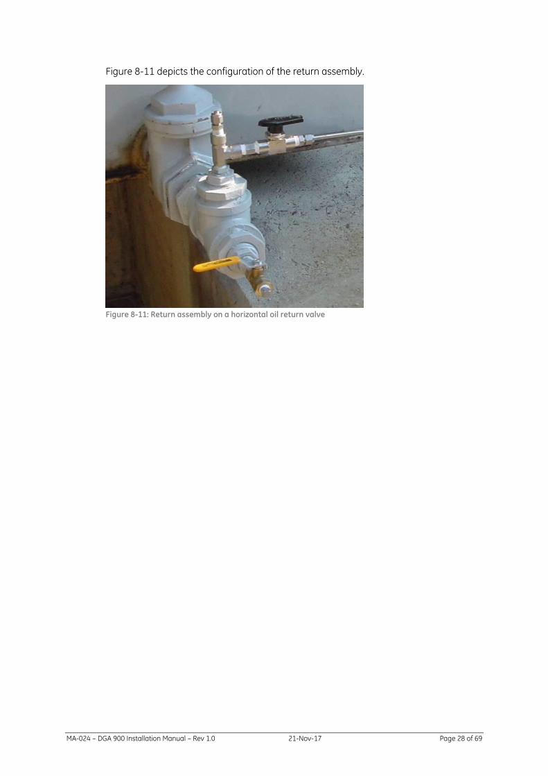
Figure 8-11 depicts the configuration of the return assembly.
Figure 8-11: Return assembly on a horizontal oil return valve

MA-024 – DGA 900 Installation Manual – Rev 1.0 21-Nov-17 Page 29 of 69
9 POWER
This section outlines the power requirements, electrical installation connections and
related aspects that must be observed.
A suitable circuit meeting the technical specification requirements must be available for the product at the time of installation. Installation must be done in accordance with local wiring regulations.
Ensure that the mains power of the product is connected to a circuit that is continually on to ensure its continuous operation.
Disconnection is through an external switch or circuit breaker that must be installed on the mains supply line where it is visible from the product, easily accessible and clearly identified as the disconnect device for the product. It shall be rated at 10 A minimum 250 V AC minimum and be approved to IEC60947-1, IEC60947-3 or other standard required by local regulations.
Before commencing any installation or maintenance work, ensure that the product is disconnected from the mains supply via the external switch or circuit breaker.
All wires and cables leading to or from the product are made through four conduit
connectors on the base of the Hub module as shown in Figure 9-1. The mains wiring
routes through the 25-mm conduit connector, while wiring for communications and
sensors route through the other conduit connectors. The PCC connection provides all
power and communications to the Analysis module as shown in Figure 8-4.
Unused conduit connectors shall be sealed. Conduit connectors may be replaced, if necessary.

MA-024 – DGA 900 Installation Manual – Rev 1.0 21-Nov-17 Page 30 of 69
Figure 9-1: Hub module — bottom plate connections
Cable glands for optional communications (M32 × 2)
PCC cable connection (to Analysis module)
Earth stud (M8)
Cable gland for optional communications (M20)
Power -in gland (M25)

MA-024 – DGA 900 Installation Manual – Rev 1.0 21-Nov-17 Page 31 of 69
9.1 PCC cable
The Power Communications and Control (PCC) cable provides a physical connection
between the two modules, supplying power to the Analysis module and
communications between the modules. The cable is plastic-sheathed with screw-lock
socket connectors. The standard cable length is 2 metres as shown in Figure 9-2, but a 5
metre or 10 metre length can be ordered depending on the mounting arrangement.
Figure 9-2: PCC cable
9.2 Safety Earth
The product has an M8 safety earth stud located on the bottom of each enclosure as
shown in Figure 8-4 and Figure 9-1.
To ensure continued safety and EMC compliance, this must be connected to earth
ground in accordance with local wiring regulations and using at least 6 mm2 (10 AWG)
wiring (see Figure 9-3).
Figure 9-3: Safety Earth
MA-024 – DGA 900 Installation Manual – Rev 1.0 21-Nov-17 Page 32 of 69
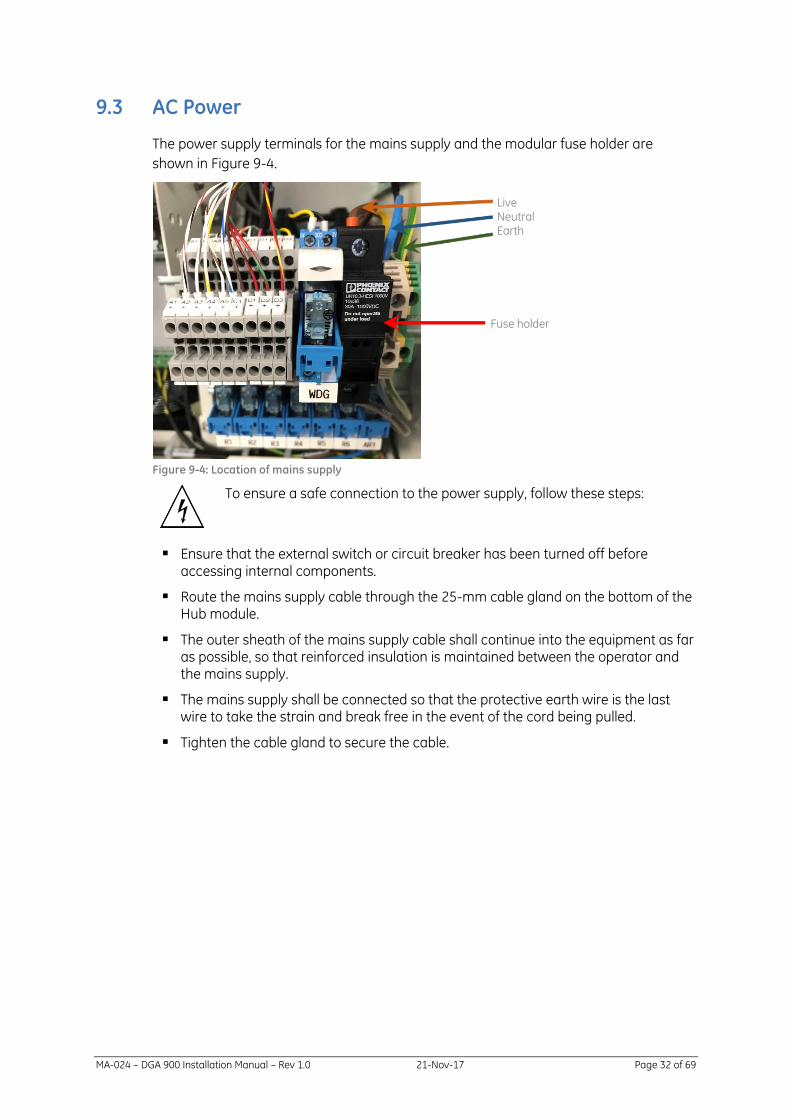
9.3 AC Power
The power supply terminals for the mains supply and the modular fuse holder are
shown in Figure 9-4.
Figure 9-4: Location of mains supply
To ensure a safe connection to the power supply, follow these steps:
▪ Ensure that the external switch or circuit breaker has been turned off before accessing internal components.
▪ Route the mains supply cable through the 25-mm cable gland on the bottom of the Hub module.
▪ The outer sheath of the mains supply cable shall continue into the equipment as far as possible, so that reinforced insulation is maintained between the operator and the mains supply.
▪ The mains supply shall be connected so that the protective earth wire is the last wire to take the strain and break free in the event of the cord being pulled.
▪ Tighten the cable gland to secure the cable.
Live NeutralEarth
Fuse holder

MA-024 – DGA 900 Installation Manual – Rev 1.0 21-Nov-17 Page 33 of 69
9.4 DC Power
The power supply terminals for the mains supply and the modular fuse holder are
shown in Figure 9-4.
Figure 9-5: Location of mains supply
To ensure a safe connection to the power supply, follow these steps:
▪ Ensure that the external switch or circuit breaker has been turned off before accessing internal components.
▪ Route the mains supply cable through the 25-mm cable gland on the bottom of the Hub module.
▪ The outer sheath of the mains supply cable shall continue into the equipment as far as possible, so that reinforced insulation is maintained between the operator and the mains supply.
▪ Tighten the cable gland to secure the cable.
Positive Negative
Fuse holder

MA-024 – DGA 900 Installation Manual – Rev 1.0 21-Nov-17 Page 34 of 69
9.5 DC Distribution
The internal DC distribution block is as shown in Figure 9-6 and is fitted to the DIN rail on
the back wall of the Hub module as shown in Figure 9-7.
Figure 9-6: DC block
Figure 9-7: DC block fitted
The DC distribution block terminals are listed below.
▪ F1 - F2: 5 x 20 mm T8 250 V: For Analysis module only.
▪ F3: 5 x 20 mm 6.3 AL 250 V fuse: Spare for customer use.
▪ F4-F8: 5 x 20 mm 6.3 AL 250 V fuse: For internal electronics.
MA-024 – DGA 900 Installation Manual – Rev 1.0 21-Nov-17 Page 35 of 69
10 ELECTRONICS
10.1 Controller PCB
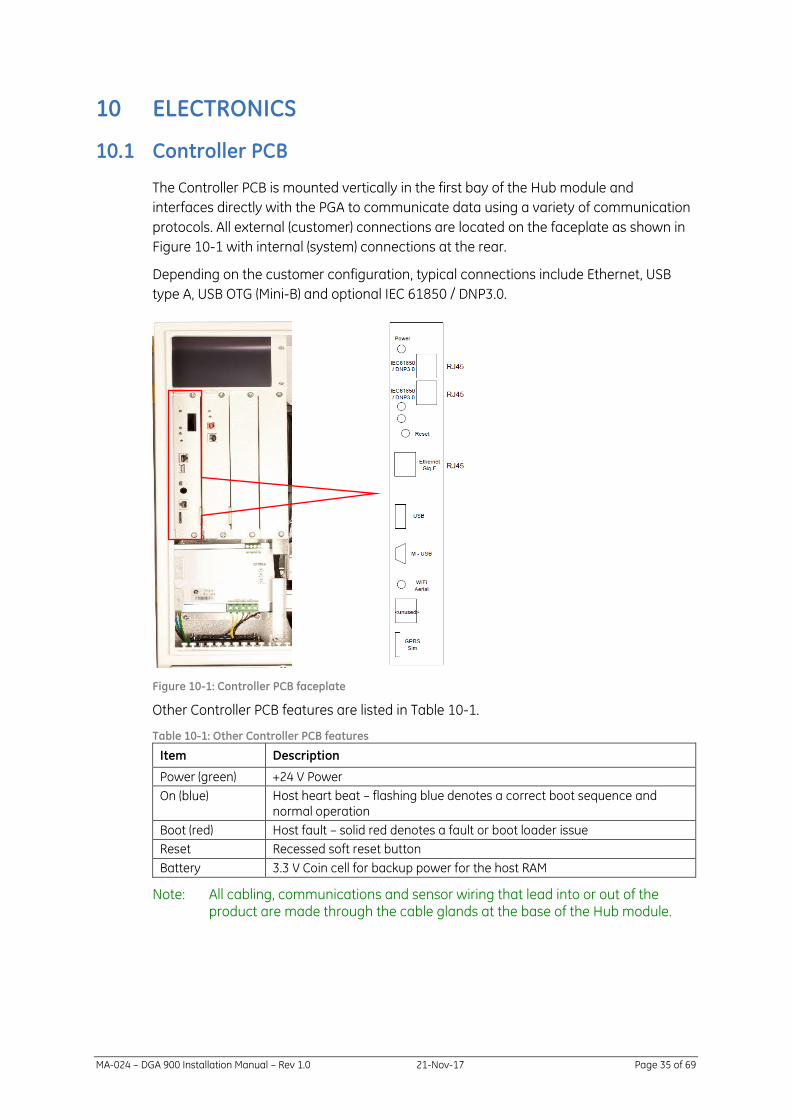
The Controller PCB is mounted vertically in the first bay of the Hub module and
interfaces directly with the PGA to communicate data using a variety of communication
protocols. All external (customer) connections are located on the faceplate as shown in
Figure 10-1 with internal (system) connections at the rear.
Depending on the customer configuration, typical connections include Ethernet, USB
type A, USB OTG (Mini-B) and optional IEC 61850 / DNP3.0.
Figure 10-1: Controller PCB faceplate
Other Controller PCB features are listed in Table 10-1.
Table 10-1: Other Controller PCB features
Item Description
Power (green) +24 V Power
On (blue) Host heart beat – flashing blue denotes a correct boot sequence and normal operation
Boot (red) Host fault – solid red denotes a fault or boot loader issue
Reset Recessed soft reset button
Battery 3.3 V Coin cell for backup power for the host RAM
Note: All cabling, communications and sensor wiring that lead into or out of the product are made through the cable glands at the base of the Hub module.

MA-024 – DGA 900 Installation Manual – Rev 1.0 21-Nov-17 Page 36 of 69
10.2 I/O PCB
The I/O PCB houses the optional analogue and digital inputs and is mounted vertically in
the second bay of the Hub module as shown in Figure 10-2 and provides a
communications interface between the customer equipment and the Controller PCB. A
standard configuration consists of one I/O PCB, but additional I/O PCBs can be hosted in
the remaining bays depending on the required accessories. Blank faceplates denote
unused bays (depending on the final configuration).
Figure 10-2: I/O PCB faceplate
The board features a power status LED and recessed reset button on the faceplate.

MA-024 – DGA 900 Installation Manual – Rev 1.0 21-Nov-17 Page 37 of 69
10.3 Battery
The product uses non-rechargeable lithium coin cell batteries (Panasonic CR2450
3 V 620 mAh) — one in the Hub module on the Controller PCB as shown in Figure 10-3,
and the other in the Analysis module on the Marshalling board as shown in Figure 10-4.
If either battery needs to be replaced, data from the product must be backed up. Failure
to do so may result in historical data loss.
Figure 10-3: Controller PCB coin cell battery
Figure 10-4: Marshalling board coin cell battery
The following steps describe how to change the battery:
1. Back up the product data — if necessary contact your GE representative.
2. Open the door on the relevant module to locate the battery on the relevant board.
3. Slide the battery out of its housing.
4. Replace with a new Panasonic CR2450 3 V 620 mAh coin cell.
5. Close the door.
There is a danger of a new battery exploding if installed incorrectly.
Dispose of the used battery in accordance with local regulations — not in a fire or with household waste. Contact your local waste disposal agency for the address of the nearest battery deposit site. Perchlorate material — special handling may apply.
See: www.dtsc.ca.gov/hazardouswaste/perchlorate/

MA-024 – DGA 900 Installation Manual – Rev 1.0 21-Nov-17 Page 38 of 69
11 RELAYS & INPUTS
11.1 Connections
A summary of the various DGA 900 connections are shown in Figure 11-1.
Figure 11-1: DGA 900 Connections

MA-024 – DGA 900 Installation Manual – Rev 1.0 21-Nov-17 Page 39 of 69
11.2 Relays
The product offers a series of relays to service various alarm conditions. All relays
supplied provide field termination for NO, NC and Common connections. See Section 4
for Technical Specifications. The relay identification is shown in Figure 11-2 and relay
terminals are shown in Figure 11-1.
Figure 11-2: Relay configuration
The relay cable sizes are listed in Table 11-1.
Table 11-1: Relay cable sizes
Relays Min (mm2) Max (mm2) AWG Strip Length (mm)
Solid 0.14 6 10 8
Flexible 0.14 4 12 8

MA-024 – DGA 900 Installation Manual – Rev 1.0 21-Nov-17 Page 40 of 69
11.2.1 Watchdog Relay
The Watchdog relay as shown in Figure 11-3 (labelled WDG) is designed to monitor the
voltage output from the PSU. If there is a 10% drop in voltage output, the watchdog
relay is de-energised alerting the customer of a power supply issue. Watchdog relay
wiring termination is shown in Figure 11-1.
Figure 11-3: Terminal and power connections with WDG
Note: The PSU has its own relay contact that the watchdog relay monitors.

MA-024 – DGA 900 Installation Manual – Rev 1.0 21-Nov-17 Page 41 of 69
11.3 Analogue and Digital Inputs
The product offers a series of field connection terminals for analogue and digital IO.
Analogue termination is as shown in Figure 11-4.
Note: These passive interfaces don’t supply a voltage to the connected device, so all connected devices must be powered independently.
Figure 11-4: Analogue customer terminals
Digital termination is as shown in Figure 11-5.
Figure 11-5: Digital customer terminals

MA-024 – DGA 900 Installation Manual – Rev 1.0 21-Nov-17 Page 42 of 69
The minimum and maximum wiring sizes for each analogue and digital input terminal is
shown in Table 11-2.
Table 11-2: Cable sizes
Screw Connectors Min (mm2) Max (mm2)
Solid 0.14 4
Flexible 0.14 4
AWG 26 12
To determine which configurable analogue inputs have been installed, see the label on
the I/O PCB faceplate, for example, as shown in Figure 11-6. In this example, the CT has
been fitted to A1, the PT100 has been fitted to A2, the 4-20 mA has been fitted to A3 and
analogue inputs 4 to 6 are empty.
Figure 11-6: I/O faceplate label
11.3.1 Current Transformer (CT) load sensor
A transformer load sensor is provided in the product installation kit to measure and
record the transformer load. The transformer load sensor is a split core current sensor
that can be installed unobtrusively around a CT line receiving a feed from the main
bushing secondary wiring (usually located within the marshalling / control cabinet of the
transformer).
It should be possible to locate a suitable current transformer with a 0 – 5 A secondary
circuit on which to mount the sensor. The sensor is supplied with 2.5 m (100 in.) of cable
and may be spliced to the required length to connect to the product with up to a total of
10 m (33 ft) of 20 AWG twisted pair cable. Longer cable lengths are possible depending
upon the quality of the cable.
The load sensor always connects directly to the terminal A1+ and A1-, as highlighted in
Figure 11-4.
11.3.2 Resistance Temperature Detector (RTD) Sensor
The RTD sensor is an optional card that is wired with a PT100 temperature sensor. A 2-
wire or 3-wire RTD can be wired to the analogue terminals as outlined below.
11.3.2.1 RTD 2-Wire
Figure 11-7 shows how the current connects to the A+ (positive) of the relevant input
and Common connects to the A- (negative) of the relevant input.

MA-024 – DGA 900 Installation Manual – Rev 1.0 21-Nov-17 Page 43 of 69
Figure 11-7: RTD 2-wire
Note: ‘x’ denotes the relevant input terminal.
11.3.2.2 RTD 3-Wire
Figure 11-8 shows how the current connects to the A+ (positive) of the relevant input
and both the Common and Lead compensation connects to the same A- (negative) of
the relevant input.
Figure 11-8: RTD 3-wire
Note: ‘x’ denotes the relevant input terminal.
11.3.3 Analogue Input 4-20 mA
The 4-20 mA analogue input can be wired directly to the relevant terminals as A2 to A6+
(positive) and A2 to A6- (negative). See Figure 11-4 for terminal locations and Figure 11-6
for supplied input configuration.
Figure 11-9: 4-20 mA
Current: 4-20 mA
Max Voltage: 5 V

MA-024 – DGA 900 Installation Manual – Rev 1.0 21-Nov-17 Page 44 of 69
11.3.4 Digital Inputs
Three digital inputs are supplied at D1 to D3. See Figure 11-5. Digital inputs are polarised
and the positive supply must be connected to the D+.
Max Current: 25 mA
Max Voltage: 24 V

MA-024 – DGA 900 Installation Manual – Rev 1.0 21-Nov-17 Page 45 of 69
12 COMMUNICATIONS
Various communication options are available for the product as outlined in Table 12-1.
The product supports simultaneous communication on several channels – up to three
masters over Ethernet, and one master on each of the serial connections (including the
USB connection) as listed in Table 12-1.
Auxiliary customer equipment can be connected via an RS-485 connection located on
the DIN rail. See Section 9.5 for +24 V customer power connection.
Table 12-1: Product communications channels
Physical Layer Protocol
MODBUS/ RTU
MODBUS/ TCP
MODBUS/ ASCII
DNP3.0 IEC61850-2
USB (OTG) - ✓ - -
RS-485 2-wire ✓ - ✓ - -
RS-485 4-wire ✓ - ✓ ✓ -
GPRS / 3G - ✓ - - -
Ethernet - ✓ - ✓ ✓
The above options are correct at the time of publication, but additional options may
become available. Please contact the GE Service Centre for further information.
12.1 Configuration
Use the HMI to configure the communications options. Refer to Chapter 6 of the DGA
900 Operator Guide for more details on using the HMI. Press Communication Settings
from the local HMI or select Settings > Communications from the remote HMI as shown
in Figure 12-1.
Figure 12-1 Local HMI and Remote HMI: Communication Settings

MA-024 – DGA 900 Installation Manual – Rev 1.0 21-Nov-17 Page 46 of 69
The Communication Settings page opens on the parameters for configuring serial
communication.
Select Ethernet on the local HMI. The default settings for Ethernet configuration are
shown in Figure 12-2.
Figure 12-2: Ethernet configuration
Select USB on the local HMI. The default settings for USB (OTG) are shown in Figure 12-3.
Figure 12-3: USB configuration
Select GSM/GPRS on the local HMI. The default settings for GSM/GPRS configuration are
shown in Figure 12-4.
Figure 12-4: GSM/GPRS configuration

MA-024 – DGA 900 Installation Manual – Rev 1.0 21-Nov-17 Page 47 of 69
12.2 RS-485
The RS-485 2-wire and RS-485 4-wire can be configured by moving the terminal link as
shown in Figure 12-5.
Figure 12-5: RS-485 connections
The RS-485 terminal connections are listed in Table 12-2.
Table 12-2: RS-485 terminal connections
Connection Description
A RS-485 2-wire (+) / RS-485 4-wire (Tx+)
B RS-485 2-wire (-) / RS-485 4-wire (Tx-)
Y RS-485 4-wire (Rx+)
Z RS-485 4-wire (Rx-)
ISO Isolated Ground
A1 Transopto 2-wire (+)
B1 Transopto 2-wire (-)
GND Ground
Note: Ensure that the RS-485 settings match those specified on the Serial Communications page of the HMI.
The default settings on the local HMI for an RS-485 configuration are shown in Figure
12-6.
Figure 12-6: RS-485 configuration

MA-024 – DGA 900 Installation Manual – Rev 1.0 21-Nov-17 Page 48 of 69
12.3 DNP3
Refer to the document CG-060 – DGA 900 DNP3 Objects & IO Points Index.
12.4 Modbus
Refer to the document CG-062 – DGA 900 Modbus IO Registers.

MA-024 – DGA 900 Installation Manual – Rev 1.0 21-Nov-17 Page 49 of 69
Appendix A Installation Tools and Supplies
The tools and supplies for a product installation are listed below. If GE performs the
installation, the GE installation engineer will provide these items:
GE-supplied Items
Qty Description
2 9/16 in. Combination wrench (must be imperial 9/16 in.)
1 ½ in. Wrench
1 30 cm (12 in.) Adjustable wrench
1 35 – 40 cm (14 in.) Pipe wrench
1 10 mm Socket and socket wrench
1 1/8 flat blade screwdriver
1 ¼ in. flat blade screwdriver
1 #2 Phillips screwdriver
1 ¼ in. Tubing bender
1 ¼ in. Tubing cutter
Deburring tool
1 8 m tape measure
1 Level capable of indicating plumb and level within 5 degrees
1 Permanent marker (fine tip)
1 22 – 14 Gauge wire cutter/stripper
1 Small diagonal cutting pliers
1 Quality vacuum pump with approximately 3 ft of clear ¼ in. tubing fitted with a ¼ in. compression fitting at the end of the tubing
1 roll 12 mm (½ in.) width PTFE pipe-sealing tape or PTFE pipe compound
25 30 cm (12 in.) Nylon UV-resistant cable ties
1 bag ¼ in. tubing P clamps
1 Mini USB cable
1 Laptop computer for commissioning the product and running the software for downloading and interpreting the results of the gas analysis. Minimum specification: Windows® 2000 or Windows® XP operating system, PII 400 MHz processor, 128 MB of RAM and 1.2 GB hard drive space, 28.8 Kbps modem or faster and USB 1.1 or faster.
Customer-supplied Items
The following tools and supplies are needed on site to secure the mounting stand (if
used), tighten the 2 in. pipe fittings (if used) and complete the installation. GE is unable to
bring the following items due to size and weight restrictions, so the customer should
provide them.
Qty Description
1 12 mm (½ in.) capacity hammer drill with 9.5 mm (3/8 in.) masonry bit
1 36 in. pipe wrench if large fittings are used to provide oil to the product
1 Scaffolding, lift or approved platform to obtain access to valves (if needed)
1 Suitable vessel to collect at least 4 litres of waste oil during the commissioning process
1 Absorbent cloths

MA-024 – DGA 900 Installation Manual – Rev 1.0 21-Nov-17 Page 50 of 69
24 M8 threaded fasteners with a recommended minimum length of 80 mm for the concrete pad

MA-024 – DGA 900 Installation Manual – Rev 1.0 21-Nov-17 Page 51 of 69
Appendix B Customer Checklist
The following checklist details items that the customer must acquire prior to the
installation:
Prepared, flat mounting surface
Parts to fabricate a mounting stand (if the product mounting stand has not been
purchased)—see Section 7.
Required number of stainless steel tubing lengths of 6 m (20 ft) each (see Section
8.3).
Fittings to adapt the transformer supply valve to a ¼ in. female NPT fitting (see
Section 8.2).
Fittings to adapt the transformer return valve to a ¼ in. female NPT fitting (see
Section 8.2).
¼ in. compression ball valve, if required (see Section 8.3).
¼ in. stainless steel compression unions (if the length of either tubing path
exceeds 6 m (20 ft) — see Section 8.3.
Communications option tested and located at the installation site (see Section
12).
Circuit capable of 100 – 250 V DC or 100 – 240 V AC, 50/60 Hz with suitable
overcurrent protection as per local regulations (see Section 9). If heat trace cable
is used, it must be on a separate circuit.
Wiring and/or conduit for connection between the terminals within the product
and to the external switch or circuit breaker. This must be performed by a
suitably qualified electrician in accordance with local wiring regulations (see
Section 9.3).
Tools and supplies needed to complete the installation (see Appendix A).

MA-024 – DGA 900 Installation Manual – Rev 1.0 21-Nov-17 Page 52 of 69
Appendix C Installation Record
Customer Contact and Site Details
Company:
Address:
City, State and Postcode (Zip):
Country:
Phone:
Installation Site Name:
Site Address:
City, State:
Postcode (Zip):
Country:
Primary Corporate Contact:
Name: Title:
Address:
City, State and Postcode (Zip):
Country:
Phone: Mobile:
Email address:
Secondary Contact Name: Mobile:
Primary Site Contact:
Name: Title:
Address:
City, State and Postcode (Zip):
Country:
Phone: Mobile:
Email address:
Secondary Contact Name: Mobile:
Site Map
Please attach a detailed map or GPS coordinates on how to locate the site.

MA-024 – DGA 900 Installation Manual – Rev 1.0 21-Nov-17 Page 53 of 69
Transformer Details
Make: Year: Years in Service:
Type:
Conservator Nitrogen Blanketed Other:
MVA Rating:
CT ratio:
Condition of Desiccant:
Attach several photos showing the transformer and surrounding area
Attach all available DGA data
Total Dissolved Gas: ___________ ppm (sum of all measured gases)
Please describe (or attach separately) details of any major maintenance actions, such as
a rebuild, vacuum degassing or filtering etc.
Transformer Oil
Oil Capacity: (in gallons) (in litres)
Manufacturer: Type:
Certified PCB free: Yes No
Temperature range at oil supply valve: High °C Low °C
Temperature range at oil return valve: High °C Low °C
Transformer Nitrogen Blanket (if applicable)
How frequently does the nitrogen bottle need to be changed?
Years Months
Headspace Pressure: psi (kPa, bar)
Pre-Installation Photographs
It is recommended that photographs of the installation site be taken in advance of the
installation to properly assess the site, aid in planning the installation and contribute to
the ‘Short Duration Safety Plan’. The following areas should be photographed:
Valves / Plumbing
Proposed Supply valve location
Proposed Return valve location
Alternative Supply valve location

MA-024 – DGA 900 Installation Manual – Rev 1.0 21-Nov-17 Page 54 of 69
Alternative Return valve location
Secondary Shut-Off valve location (if needed)
Oil supply & return routing (the ¼ in. stainless steel tubing)
Proposed Product location
Overview from front
Overview from left side
Overview from back
Overview from right side
Proposed Cable routing and connection locations
Communication cable routing (include terminations)
Power cable routing (include terminations)
Transformer
Nameplate photo
Oil temperature gauge
Oil level gauge
Control panel with door open
Overview of each side
Cooling loop(s)
Conservator with close-ups of gauges
Pumps
Desiccant
Nitrogen Cylinder / Regulator gauges (if transformer is nitrogen-blanketed) (both Output & Cylinder psig)
Additional Photographs
Any additional devices used in conjunction with the installation, such as junction boxes, telephone line sharing devices, alternative communication devices etc.
Overall site photos
Any other useful photos
MA-024 – DGA 900 Installation Manual – Rev 1.0 21-Nov-17 Page 55 of 69
Appendix D Tubing Specification and Ordering Details
Specifications
Rigid Tubing ¼ in. OD × 0.035 in. wall T316 seamless stainless steel tubing (6.35 mm OD × 0.889 mm wall) (ASTM A269 / A213).
Flexible Hose ¼ in. ID low pressure, 316 stainless steel braid over stainless steel metal flexible hose with welded ¼ in. compression fittings on each end.
Order Information (E.g. Swagelok)
Rigid Tubing Rigid tubing can be ordered from Swagelok in advance of the installation. For example, a 20-foot length would have part number SS-T4-S-035-20 (see the Swagelok website www.swagelok.com or your local Swagelok representative).
Flexible Hose Flexible hose can be ordered from Swagelok, but must be ordered in custom lengths in advance of the installation. For example, a custom 8 meter FL series hose would have part number SS FL4TA4TA4-800 (specified in centimetres) (see the Swagelok website www.swagelok.com or your local Swagelok representative).
Do not use copper tubing (See Section D.6).
Tubing Unions
Tubing Unions connect two pieces of the above ¼ in. tubing together. GE recommend:
▪ Swagelok: SS-400-6 Stainless Union, ¼ in. OD
▪ Ham-Let: 762L SS 1/4 Stainless Union, ¼ in. OD
Shut-Off Valve
If the oil supply or return valve is located more than 6 ft (1.82 m) above the base of the
transformer, use a Swagelok tube fitting (SS-4P4T Stainless Plug Valve, ¼ in.) or a Ham-
Let tube fitting (H800MSSL Stainless Plug Valve, ¼ in.) as directed in this procedure.
6 mm Tubing Adaptors
If ¼ in. tubing is not available, 6 mm stainless steel tubing may be used, but the
maximum tubing run may be reduced, and ¼ in. to 6 mm tubing adaptors must be used.
Consult with the GE Service Centre. The adaptors should be Swagelok (SS-6M0-R-4
Stainless Reducer, 6 mm OD – ¼ in. OD) or Ham-Let (767LT SS Stainless Reducer, 6 mm
OD – ¼ in. OD). At least eight of these are required for the installation.

MA-024 – DGA 900 Installation Manual – Rev 1.0 21-Nov-17 Page 56 of 69
Do not use 6 mm tubing without the above adaptors. To do so would void the warranty.
Tubing Material
Stainless steel is the only material that should be used. The use of any other tubing material will cause reliability issues or inaccurate results and void the warranty of the product. GE does not support the use of copper tubing for the installation of its transformer analysis products. The reasons for this are outlined below.
Flow Rate
The solid seamless stainless steel tubing that GE specifies is 316 Stainless Steel, 1/4 in.
OD with a 0.035 in. thick wall. Most 1/4 in. copper tubing has a greater wall thickness
which reduces the flow rate rendering it too fragile to place in the field. Bends in
standard soft copper tubing crush and deform more easily, which can reduce the flow
rate than would otherwise be the case with properly bent stainless steel tubing.
Connection reliability and physical damage
The primary design and installation principles are to never let:
oil escape from the transformer during operation.
air enter the transformer during operation.
In general, copper tubing is too soft to create a reliable long term seal in the vibratory
environment of a transformer — the connections eventually leak. The softness of copper
tubing also make it prone to damage post installation — maintenance and service
activities near the transformer could potentially kink, pinch or tear connections.
Compounds in the transformer oil that react with copper
Transformer oils contain compounds that can react with copper. One notable
compound is acetylene, which reacts with copper to form copper acetylide. This creates
two related problems:
Copper acetylide is a highly explosive compound and for regulatory and health and safety reasons, GE equipment or installations cannot create these compounds.
The reaction changes the chemical makeup of the oil before it reaches the sensor in the product. This causes the product to measure acetylene and possibly other gases inaccurately.
Although a transformer already contains copper, GE monitoring and diagnostic
equipment is designed to accurately measure the gases in the oil of a transformer
without affecting the oil.

MA-024 – DGA 900 Installation Manual – Rev 1.0 21-Nov-17 Page 57 of 69
GE will not guarantee or perform warranty work on a product that has been installed using copper tubing or any other tubing, other than stainless steel, as specified above.
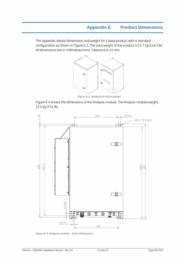
MA-024 – DGA 900 Installation Manual – Rev 1.0 21-Nov-17 Page 58 of 69
Appendix E Product Dimensions
This appendix details dimensions and weight for a base product with a standard
configuration as shown in Figure E-1. The total weight of the product is 52.7 kg (116.3 lb).
All dimensions are in millimetres (mm). Tolerance is ±5 mm.
Figure E-1: Analysis & Hub modules
Figure E-4 shows the dimensions of the Analysis module. The Analysis module weighs
33.4 kg (73.6 lb).
Figure E-2: Analysis module – front dimensions

MA-024 – DGA 900 Installation Manual – Rev 1.0 21-Nov-17 Page 59 of 69
Figure E-3: Analysis module – side dimensions

MA-024 – DGA 900 Installation Manual – Rev 1.0 21-Nov-17 Page 60 of 69
Figure E-4: Analysis module – bottom dimensions

MA-024 – DGA 900 Installation Manual – Rev 1.0 21-Nov-17 Page 61 of 69
Figure E-5 shows the dimensions of the Hub module. The Hub module weighs 18.5 kg
(40.8 lb).
Figure E-5: Hub module – front dimensions

MA-024 – DGA 900 Installation Manual – Rev 1.0 21-Nov-17 Page 62 of 69
Figure E-6: Hub module – side dimensions

MA-024 – DGA 900 Installation Manual – Rev 1.0 21-Nov-17 Page 63 of 69
Figure E-7: Hub module – bottom dimensions

MA-024 – DGA 900 Installation Manual – Rev 1.0 21-Nov-17 Page 64 of 69
Appendix F Mounting Stand Dimensions & Assembly
Figure F-1 illustrates the product mounting stands with the Analysis and Hub modules.
Each module is mounted on a separate stand. The same type of stand is used for each
module. Each mounting stand weighs 20 kg (45 lb). All dimensions are in millimetres
(mm). Tolerance is ±5 mm.
Figure F-1: Mounting stand – Analysis & Hub modules

MA-024 – DGA 900 Installation Manual – Rev 1.0 21-Nov-17 Page 65 of 69
Figure F-2 shows a front-dimensioned view of the mounting stand with and without a
module mounted.
Figure F-2: Mounting stand dimensions – front
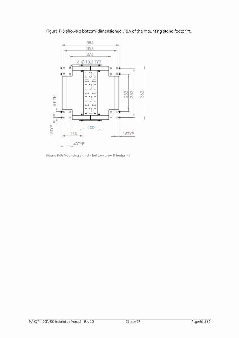
MA-024 – DGA 900 Installation Manual – Rev 1.0 21-Nov-17 Page 66 of 69
Figure F-3 shows a bottom-dimensioned view of the mounting stand footprint.
Figure F-3: Mounting stand – bottom view & footprint
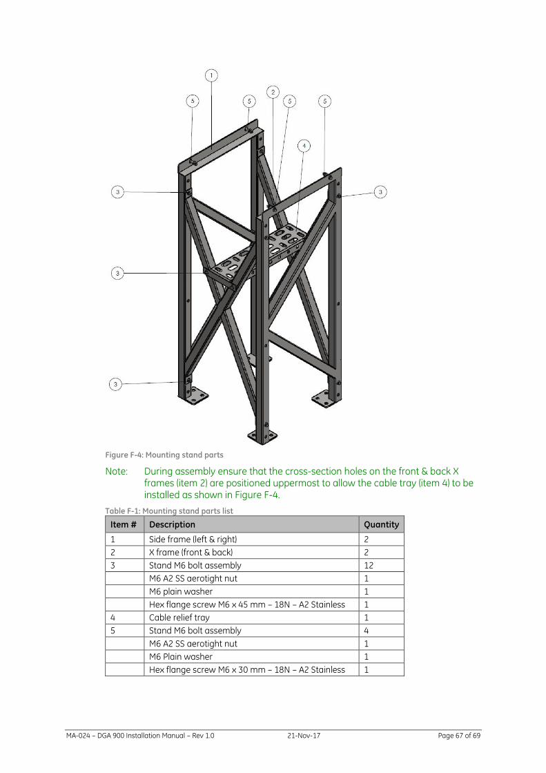
MA-024 – DGA 900 Installation Manual – Rev 1.0 21-Nov-17 Page 67 of 69
Figure F-4: Mounting stand parts
Note: During assembly ensure that the cross-section holes on the front & back X frames (item 2) are positioned uppermost to allow the cable tray (item 4) to be installed as shown in Figure F-4.
Table F-1: Mounting stand parts list
Item # Description Quantity
1 Side frame (left & right) 2
2 X frame (front & back) 2
3 Stand M6 bolt assembly 12
M6 A2 SS aerotight nut 1
M6 plain washer 1
Hex flange screw M6 x 45 mm – 18N – A2 Stainless 1
4 Cable relief tray 1
5 Stand M6 bolt assembly 4
M6 A2 SS aerotight nut 1
M6 Plain washer 1
Hex flange screw M6 x 30 mm – 18N – A2 Stainless 1

Appendix G Heat Trace Cable
If the oil temperature in the tubing can reach temperatures below −20 °C, the
recommendation is to use heat trace cable on the tubing.
The customer is responsible for supplying the heat trace cable, which must be installed
by a qualified electrician. GE service personnel are available to advise the customer and
work with the company’s electrician to install the heat trace cable.
The information below is intended to be of a general nature. Detailed information
relating to the installation steps for heat trace are outside the scope of this manual.
Installation Requirements
Installation of heat trace cable must be done by a qualified electrician familiar with local
wiring regulations.
The heat trace cable selected shall have all necessary safety approvals required by local
wiring regulations. The heat trace cable rating shall be suitable for the voltage of the
power source, the temperature rating required, and the size of tubing it is to be installed
on.
Heat trace cable must be installed in accordance with the manufacturer’s instructions
and local wiring regulations. Attention should be paid to requirements for circuit
protection and power supply.
The heat trace cable shall be controlled by a thermostat to prevent continuous
operation.