gca multi-softcore architecture for agent systems simulation
TRANSCRIPT

GCA Multi-Softcore Architecture for Agent SystemsSimulation
Christian Schack, Wolfgang Heenes, Rolf Hoffmann{schaeck,heenes,hoffmann}@ra.informatik.tu-darmstadt.de
Abstract:The GCA (Global Cellular Automata) model consists of a collection of cells which
change their states synchronously depending on the states of their neighbors like in theclassical CA (Cellular Automata) model. In differentiation to the CA model the neigh-bors are not fixed and local, they are variable and global. The GCA model is applicableto a wide range of parallel algorithms. The application in this paper is multi-agent be-havior simulation. By using the GCA model many multi-agent behaviors can easilybe described and efficiently simulated. A general purpose multiprocessor architectureto accelerate the simulation of multi-agent behaviors based on the massively parallelGCA model is presented. In contrast to a special purpose implementation of a GCA al-gorithm the multiprocessor system allows the implementation in a flexible way throughprogramming, thus simulating different behaviors on the same architecture. The im-plemented architecture mainly consists of a set of processors (Nios II) and a network.The Nios II features a general-purpose RISC CPU architecture designed to addressa wide range of applications. Three different networks have been implemented andevaluated with regard to the multi-agent simulation application. A system with up to16 processors was implemented as a prototype on an FPGA.
1 Introduction
Simulation of multi-agent systems are used in order to
(A) observe interesting behaviors in systems modeled with agents (problems in physics,chemistry, biology, nano technology, etc.). [Klu01, DJT01]
(B) to solve computational tasks modeled with agents. [FS05]
(C) evaluate the performance (fitness) of a multi-agent system during heuristic opti-mization procedures. Thereby the behavior of agents is optimized in order to solvea given global task. [KEFH09]
The simulation of multi-agent systems with many agents and complex behaviors of theagents is a time-consuming task. We will present different multi-softcore FPGA architec-tures to accelerate the simulation on a two dimensional grid. The aim is to find a flexi-ble, customizable and programmable architecture to accelerate the simulation of differentagent behaviors. There is a trade-off between a dedicated hardware implementation and aprogrammable architecture. To provide a programmable architecture without the need of
resynthesizing, a softcore processor such as the NIOS II is a good choice. The NIOS IIprocessor comes in three different speed grades allowing to adjust the overall architecturein order to gain the best performance out of it. The processor can be easily programmedin C by using the Eclipse based NIOS II IDE. Loading the developed architecture with anew agent behavior is easy and transparent, meaning that the programmer does not needto be fully aware of the underlying hardware architecture. This also allows to integrate fu-ture innovations without changing the complete software code. Multiple NIOS II softcoresare used to accelerate the simulation by distributing the whole task among the availableprocessors.
GCA Model
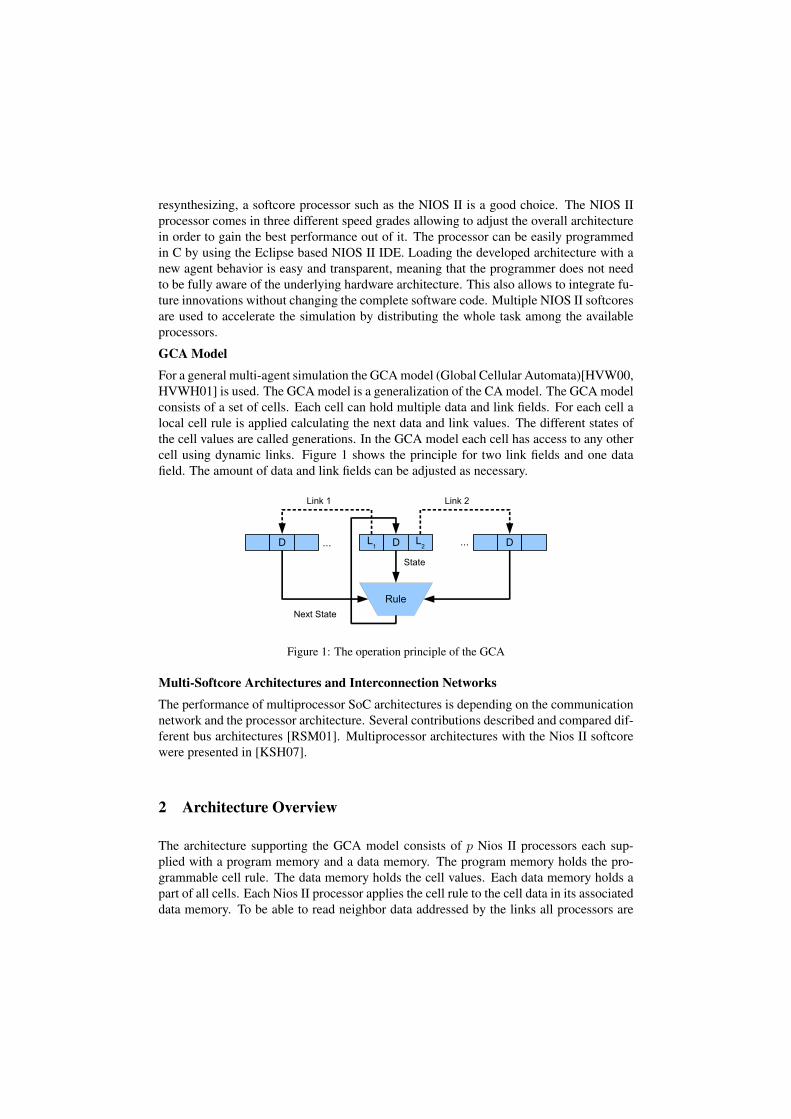
For a general multi-agent simulation the GCA model (Global Cellular Automata)[HVW00,HVWH01] is used. The GCA model is a generalization of the CA model. The GCA modelconsists of a set of cells. Each cell can hold multiple data and link fields. For each cell alocal cell rule is applied calculating the next data and link values. The different states ofthe cell values are called generations. In the GCA model each cell has access to any othercell using dynamic links. Figure 1 shows the principle for two link fields and one datafield. The amount of data and link fields can be adjusted as necessary.
Figure 1: The operation principle of the GCA
Multi-Softcore Architectures and Interconnection Networks
The performance of multiprocessor SoC architectures is depending on the communicationnetwork and the processor architecture. Several contributions described and compared dif-ferent bus architectures [RSM01]. Multiprocessor architectures with the Nios II softcorewere presented in [KSH07].
2 Architecture Overview
The architecture supporting the GCA model consists of p Nios II processors each sup-plied with a program memory and a data memory. The program memory holds the pro-grammable cell rule. The data memory holds the cell values. Each data memory holds apart of all cells. Each Nios II processor applies the cell rule to the cell data in its associateddata memory. To be able to read neighbor data addressed by the links all processors are
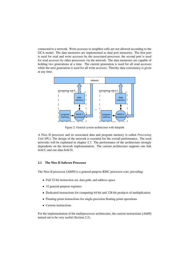
connected to a network. Write accesses to neighbor cells are not allowed according to theGCA model. The data memories are implemented as dual port memories. The first portis used for read and write accesses by the associated processor, the second port is usedfor read accesses by other processors via the network. The data memories are capable ofholding two generations at a time. The current generation is used for all read accesseswhile the next generation is used for all write accesses. Thereby data consistency is givenat any time.
Figure 2: General system architecture with datapath
A Nios II processor and its associated data and program memory is called ProcessingUnit (PU). The design of the network is essential for the overall performance. The usednetworks will be explained in chapter 2.3. The performance of the architecture stronglydependents on the network implementation. The current architecture supports one linkfield L and one data field D.
2.1 The Nios II Softcore Processor
The Nios II processor [Alt09] is a general-purpose RISC processor core, providing:
• Full 32-bit instruction set, data path, and address space
• 32 general-purpose registers
• Dedicated instructions for computing 64-bit and 128-bit products of multiplication
• Floating-point instructions for single-precision floating-point operations
• Custom instructions
For the implementation of the multiprocessor architecture, the custom instructions [Alt09]turned out to be very useful (Section 2.2).
2.2 Custom Instruction
We extended the Nios II instruction set with a parametrized custom instruction. The cus-tom instruction can be specified by one of the following functions:
(1) AUTO GET L: automatic decision between internal/external read of the link L basedon processor ID comparison
(2) AUTO GET D: automatic decision between internal/external read of the data Dbased on processor ID comparison
(3) INTERNAL GET L: internal read of the link L from memory
(4) INTERNAL GET D: internal read of the data D from memory
(5) SET LS: write link L to the internal memory and shift right by one for easier ac-cesses arranged by the power of two
(6) SET L: write link L to the internal memory
(7) EXTERNAL GET L: read link L by using the network
(8) SET D: write data D to the internal memory
(9) EXTERNAL GET D: read data D by using the network
(10) NEXTGEN: processor synchronization command (Section 2.4)
The automatic read functions (1-2) decide between an internal or external read access bycomparing the address with the processor ID. The actual read process is then mapped ontothe right read function (2,3,7,9) named LOCAL GET {X} or GET {X}where X∈ {L,D}.This process does not need an extra clock cycle and should therefore always be favoredover the separated access functions.
2.3 Network
The interconnection between the processors can be implemented using different networktopologies. We have previously used an omega network. [SHH09a, SHH09b] The omeganetwork is good to use for regular accesses (power of two) e.g. for the bitonic sort algo-rithm. As the arbitration is done within the network all read accesses to the network haveto be synchronized. For multi-agent simulation the use of such a network is not applicablebecause the access patterns are arbitrary. Therefore we have investigated other networksto gain the best performance for such an application.

The requirements for the network are:
• fast access to neighbor cells, reduce wait cycles
• reduce the amount of collisions/congestion
• fair and easy arbitration
• keep the system frequency high
Registered Ring
The registered ring network contains a register stage for each processor. Each processorcan only read from and write to its own register stage. At each clock cycle the data isforwarded from stage N to stage N + 1 mod p. The ring bus consists of a request flag,an acknowledge flag, an address and a data field (Figure 3). The address is further dividedinto a processor ID and the data memory address.
Figure 3: Register fields on the registered ring network
If the register stage of a processor is free (request and acknowledge flag is zero) the pro-cessor can perform a write access to the network. In that case the processor sets the requestflag to one, writes the address of the requested cell onto the address part of the bus and itsown ID onto the data part of the bus. The ID of the sending processor is needed for thereply packet. The requesting processor is stalled until the request has been successfullyprocessed.
Each processing unit listens for incoming requests on the ring. If the request flag is setand the address is within the processors address space, the request is removed from thering by setting the request flag to zero. If a processing unit is executing a read request allfollowing requests are forwarded on the ring. As soon as the processing unit has finishedthe execution a new read access can be executed. Note that there is a difference between theprocessor itself and the processing unit the processor belongs to (Figure 2). A processingunit can execute incoming read request from the ring in parallel to and without interruptingits processor.
After the request has been processed and the requested data is available to be send back,the processing unit checks if the register stage is free. The data is then written onto thedata part of the bus, the ID of the requesting processor is written onto the address part ofthe bus and the acknowledgment flag is set to one.
The processor that initiated the request listens for acknowledgment packets with its ownID. If such a packet is received it is removed from the ring. The acknowledgment flag isset to zero and the data is copied from the ring and advanced to the processor.
The protocol handling is done transparent and does not require action from the Nios IIprocessor nor does a request disturb another processor with its execution.
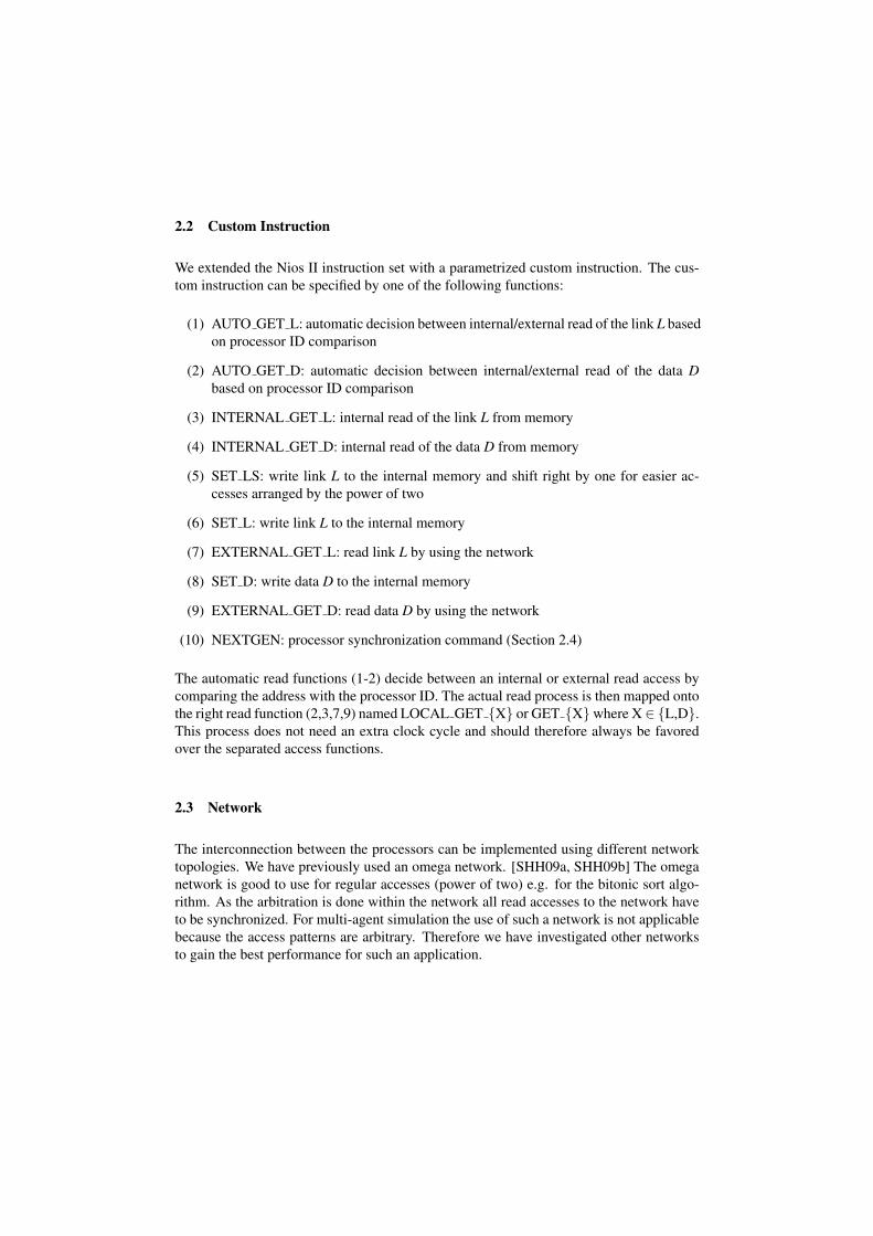
Figure 4: Registered ring network for eight processors (showing two PUs)
Deadlocks are not possible as there are as many register stages as processors. Each pro-cessor can only put one request on the ring at a time. In the worst case scenario all registerstages contain requests from different processors. These will be removed from the ringas soon as they arrive at the destination processing unit. An acknowledgment can only bewritten onto the ring if the request has been removed in advance. The access time for eachrequest lasts p clock cycles. Accesses to the internal memory via the ring network last 2 ·pclock cycles and should therefore be avoided which can be easily accomplished by usingthe automatic read functions (Section 2.2)
Bus
The bus network connects all processing units with a shared bus. As there are no tristatebuffers in the FPGA the common bus is implemented using multiplexers. The challengingpart is the implementation of an efficient arbiter. Two approaches have been implemented,a round robin arbiter and a dynamic prioritized arbiter.
Round Robin Arbiter (BRRA). The round robin arbiter performs a check on the requestsignal of each processor in a cyclic way. If there is a request on the request signal N theaddress of this request is forwarded onto the bus. After the data has been read from thebus the request signal N + 1 mod p is checked. This approach avoids starvation of otherprocessors trying to read data via the bus.
Dynamic Prioritized Arbiter (BDPA). The dynamic prioritized arbiter checks the requestsignals by searching the processor with the highest ID that wants to read via the network.The IDs of the processors are compared with a comparator tree (Figure 5). A processorwith an active request signal advances its ID otherwise zero through the comparator tree.The comparator tree finds the highest processor ID with an active request and forwardsthis request with its corresponding address signals onto the bus.

Figure 5: Comparator tree for eight processors
2.4 Generation Synchronization
All processors run independently from each other which leads to unsynchronized exe-cutions of the processors. To ensure data integrity a special synchronization point wasintroduced. The synchronization point, implemented with a custom instruction functionas described in section 2.2 (function 10), ensures that at a certain time all processors haveexecuted the current generation and are ready to start execution of the next generation. Abarrier-synchronization technique [Ung97, S. 165] is implemented by AND gating.
3 Agent Behavior Rule (Example)
As an example the moving behavior of agents in a 2D grid is modelled. The agent’sbehavior, generally called the cell rule, is implemented as C code (Listing 1) running onthe Nios II processors. The cell rule which is applied to all cells differs in three cases. Thethree cases are: empty cell (EC), agent cell (AC), block cell (BC).
EC: An empty cell checks the four neighbors located north (E1), south (E5), east (E2)and west (E4) of it. If there is exactly one neighbor cell with an agent that wantsto move to the empty cell the agent is copied to it. The neighbor cell can not bedeleted by the empty cell as there is no write access to neighbor cells. The left agentin figure 6 shows this situation.
AC: An agent cell checks four neighbor cells (A1, A2, A3, A5) located in the movingdirection of the agent. For the front cell (A3) an easy check is executed as this cellonly needs to be empty. The remaining three cells (A1, A2, A3) are checked for anagent with a moving direction to the front cell (A3). If that is the case none of theagents can move to this cell to avoid a collision. If only the agent from the current
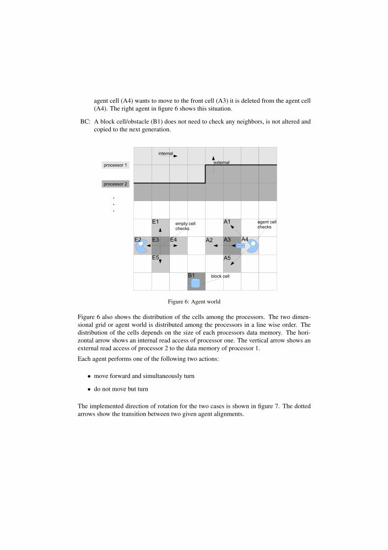
agent cell (A4) wants to move to the front cell (A3) it is deleted from the agent cell(A4). The right agent in figure 6 shows this situation.
BC: A block cell/obstacle (B1) does not need to check any neighbors, is not altered andcopied to the next generation.
Figure 6: Agent world
Figure 6 also shows the distribution of the cells among the processors. The two dimen-sional grid or agent world is distributed among the processors in a line wise order. Thedistribution of the cells depends on the size of each processors data memory. The hori-zontal arrow shows an internal read access of processor one. The vertical arrow shows anexternal read access of processor 2 to the data memory of processor 1.
Each agent performs one of the following two actions:
• move forward and simultaneously turn
• do not move but turn
The implemented direction of rotation for the two cases is shown in figure 7. The dottedarrows show the transition between two given agent alignments.
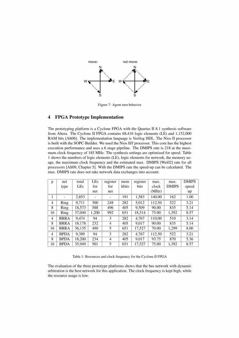
Figure 7: Agent turn behavior
4 FPGA Prototype Implementation
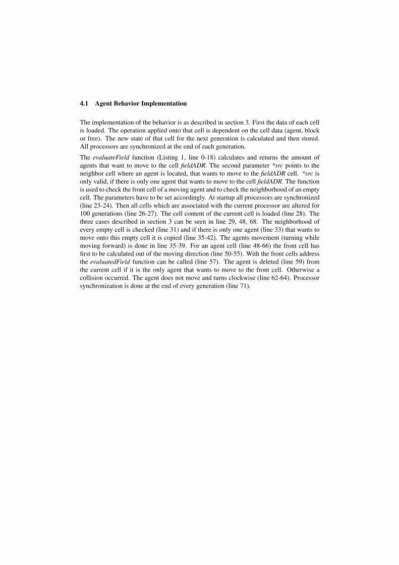
The prototyping platform is a Cyclone FPGA with the Quartus II 8.1 synthesis softwarefrom Altera. The Cyclone II FPGA contains 68,416 logic elements (LE) and 1,152,000RAM bits [Alt06]. The implementation language is Verilog HDL. The Nios II processoris built with the SOPC-Builder. We used the Nios II/f processor. This core has the highestexecution performance and uses a 6 stage pipeline. The DMIPS rate is 218 at the maxi-mum clock frequency of 185 MHz. The synthesis settings are optimized for speed. Table1 shows the numbers of logic elements (LE), logic elements for network, the memory us-age, the maximum clock frequency and the estimated max. DMIPS [Wei02] rate for allprocessors [Alt09, Chapter 5]. With the DMIPS rate the speed-up can be calculated. Themax. DMIPS rate does not take network data exchanges into account.
p net total LEs register mem register max. max. DMIPStype LEs for for kbits bits clock DMIPS speed
net net (MHz) up1 - 2,853 - - 191 1,583 140.00 162 1.004 Ring 9,711 300 248 282 5,012 112.50 522 3.218 Ring 18,573 588 496 405 9,509 90.00 835 5.14
16 Ring 37,040 1,200 992 651 18,514 75.00 1,392 8.574 BRRA 9,474 94 3 282 4,767 110,00 510 3.148 BRRA 18,178 232 4 405 9,017 90.00 835 5.14
16 BRRA 36,135 490 5 651 17,527 70.00 1,299 8.004 BPDA 9,389 94 3 282 4,767 112.50 522 3.218 BPDA 18,200 234 4 405 9,017 93.75 870 5.36
16 BPDA 35,949 501 5 651 17,527 75.00 1,392 8.57
Table 1: Resources and clock frequency for the Cyclone II FPGA
The evaluation of the three prototype platforms shows that the bus network with dynamicarbitration is the best network for this application. The clock frequency is kept high, whilethe resource usage is low.
4.1 Agent Behavior Implementation
The implementation of the behavior is as described in section 3. First the data of each cellis loaded. The operation applied onto that cell is dependent on the cell data (agent, blockor free). The new state of that cell for the next generation is calculated and then stored.All processors are synchronized at the end of each generation.
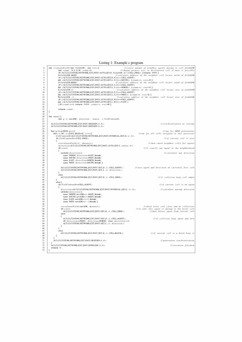
The evaluateField function (Listing 1, line 0-18) calculates and returns the amount ofagents that want to move to the cell fieldADR. The second parameter *src points to theneighbor cell where an agent is located, that wants to move to the fieldADR cell. *src isonly valid, if there is only one agent that wants to move to the cell fieldADR. The functionis used to check the front cell of a moving agent and to check the neighborhood of an emptycell. The parameters have to be set accordingly. At startup all processors are synchronized(line 23-24). Then all cells which are associated with the current processor are altered for100 generations (line 26-27). The cell content of the current cell is loaded (line 28). Thethree cases described in section 3 can be seen in line 29, 48, 68. The neighborhood ofevery empty cell is checked (line 31) and if there is only one agent (line 33) that wants tomove onto this empty cell it is copied (line 35-42). The agents movement (turning whilemoving forward) is done in line 35-39. For an agent cell (line 48-66) the front cell hasfirst to be calculated out of the moving direction (line 50-55). With the front cells addressthe evaluatedField function can be called (line 57). The agent is deleted (line 59) fromthe current cell if it is the only agent that wants to move to the front cell. Otherwise acollision occurred. The agent does not move and turns clockwise (line 62-64). Processorsynchronization is done at the end of every generation (line 71).
Listing 1: Example c program0 i n t e v a l u a t e F i e l d ( i n t fieldADR , i n t ∗s r c ){ / / r e t u r n amount o f n e i g h b o r a g e n t s moving t o c e l l f i e ldADR1 i n t count , N, S , E ,W; c o u n t =0 ; / / change p o i n t e r ∗s r c t o d e s t i n a t i o n c e l l i f move i s p o s s i b l e2 i f ( ALT CI CUSTOM NETWORK EXT INST (AUTO GET D , fieldADR , 0 ) ! = CELL FREE ) {re turn 9999;}3 N=fieldADR−MAXY; / / c a l c u l a t e a d d r e s s o f t h e n e i g h b o r c e l l l o c a t e n o r t h o f f i e ldADR4 i f ( ( ALT CI CUSTOM NETWORK EXT INST (AUTO GET D , N, 0 ) = =CELL AGENT)5 && ( ALT CI CUSTOM NETWORK EXT INST ( AUTO GET L , N, 0 ) = =SOUTH) ) {c o u n t ++; ∗s r c =N;}6 S=fieldADR+MAXY; / / c a l c u l a t e a d d r e s s o f t h e n e i g h b o r c e l l l o c a t e s o u t h o f f i e ldADR7 i f ( ( ALT CI CUSTOM NETWORK EXT INST (AUTO GET D , S , 0 ) = =CELL AGENT)8 && ( ALT CI CUSTOM NETWORK EXT INST ( AUTO GET L , S , 0 ) = =NORTH) ) {c o u n t ++; ∗s r c =S;}9 E=fieldADR +1; / / c a l c u l a t e a d d r e s s o f t h e n e i g h b o r c e l l l o c a t e e a s t o f f i e ldADR
10 i f ( ( ALT CI CUSTOM NETWORK EXT INST (AUTO GET D , E , 0 ) = =CELL AGENT)11 && ( ALT CI CUSTOM NETWORK EXT INST ( AUTO GET L , E , 0 ) = =WEST) ) {c o u n t ++; ∗s r c =E;}12 W=fieldADR−1; / / c a l c u l a t e a d d r e s s o f t h e n e i g h b o r c e l l l o c a t e wes t o f f i e ldADR13 i f ( ( ALT CI CUSTOM NETWORK EXT INST (AUTO GET D ,W, 0 ) = =CELL AGENT)14 && ( ALT CI CUSTOM NETWORK EXT INST ( AUTO GET L ,W, 0 ) = =EAST ) )15 { i f ( count >=1) re turn 9999 ; c o u n t ++; ∗s r c =W;}1617 re turn c o u n t ;18 }1920 i n t main (){21 i n t g , i i , newADR , d i r e c t i o n , sou rce , c , C e l l C o n t e n t D ;2223 ALT CI CUSTOM NETWORK EXT INST (NEXTGEN, 0 , 0 ) ; / / s y n c h r o n i z a t i o n a t s t a r t u p24 ALT CI CUSTOM NETWORK EXT INST (NEXTGEN, 0 , 0 ) ;2526 f o r ( g =0; g<GENS; g++){ / / run f o r GENS g e n e r a t i o n s27 f o r ( i i =SC ; i i<LOCL BLKS+SC ; i i ++){ / / run f o r a l l c e l l s a s s i g n e d t o t h i s p r o c e s s o r28 C e l l C o n t e n t D =ALT CI CUSTOM NETWORK EXT INST ( INTERNAL GET D , i i , 0 ) ;29 i f ( C e l l C o n t e n t D ==CELL FREE ) / / i f c u r r e n t c e l l i s f r e e30 {31 c= e v a l u a t e F i e l d ( i i , &s o u r c e ) ; / / t h e n check n e i g h b o r c e l l s f o r a g e n t s32 d i r e c t i o n =ALT CI CUSTOM NETWORK EXT INST ( AUTO GET L , sou rce , 0 ) ;33 i f ( c ==1) / / i f e x a c t l y one a g e n t i n t h e ne ighborhood34 {35 sw i t ch ( d i r e c t i o n ){ / / c a l c u l a t e new d i r e c t i o n36 case NORTH: d i r e c t i o n =EAST ; break ;37 case SOUTH: d i r e c t i o n =WEST; break ;38 case EAST : d i r e c t i o n =NORTH; break ;39 case WEST: d i r e c t i o n =SOUTH; break ;}4041 ALT CI CUSTOM NETWORK EXT INST ( SET D , i i , CELL AGENT ) ; / / save a g e n t and d i r e c t i o n on c u r r e n t l y f r e e c e l l42 ALT CI CUSTOM NETWORK EXT INST ( SET L , i i , d i r e c t i o n ) ;43 }44 e l s e45 ALT CI CUSTOM NETWORK EXT INST ( SET D , i i , CELL FREE ) ; / / i f c o l l i s i o n keep c e l l empty46 }47 e l s e{48 i f ( C e l l C o n t e n t D ==CELL AGENT) / / i f c u r r e n t c e l l i s an a g e n t49 {50 d i r e c t i o n =ALT CI CUSTOM NETWORK EXT INST ( INTERNAL GET L , i i , 0 ) ; / / c a l c u l a t e moving d i r e c t i o n51 sw i t ch ( d i r e c t i o n ){52 case NORTH: newADR= i i−MAXY; break ;53 case SOUTH: newADR= i i +MAXY; break ;54 case EAST : newADR= i i +1 ; break ;55 case WEST: newADR= i i−1;break ;}5657 c= e v a l u a t e F i e l d (newADR , &s o u r c e ) ; / / check f r o n t c e l l ( f r e e and no c o l l i s i o n )58 i f ( c ==1) / / i f o n l y t h i s a g e n t i s moving t o t h e f r o n t c e l l59 ALT CI CUSTOM NETWORK EXT INST ( SET D , i i , CELL FREE ) ; / / t h e n d e l e t e a g e n t from c u r r e n t c e l l60 e l s e61 {62 ALT CI CUSTOM NETWORK EXT INST ( SET D , i i , CELL AGENT ) ; / / i f c o l l i s i o n keep a g e n t and t u r n63 i f ( d i r e c t i o n ==WEST) d i r e c t i o n =NORTH; e l s e d i r e c t i o n +=2;64 ALT CI CUSTOM NETWORK EXT INST ( SET L , i i , d i r e c t i o n ) ;65 }66 }67 e l s e68 ALT CI CUSTOM NETWORK EXT INST ( SET D , i i , CELL BLOCK ) ; / / i f c u r r e n t c e l l i s a b l o c k keep i t69 }70 }71 ALT CI CUSTOM NETWORK EXT INST (NEXTGEN, 0 , 0 ) ; / / g e n e r a t i o n s y n c h r o n i z a t i o n72 }73 ALT CI CUSTOM NETWORK EXT INST (DONE EXE , 0 , 0 ) ; / / e x e c u t i o n f i n i s h e d74 re turn 0 ;75 }
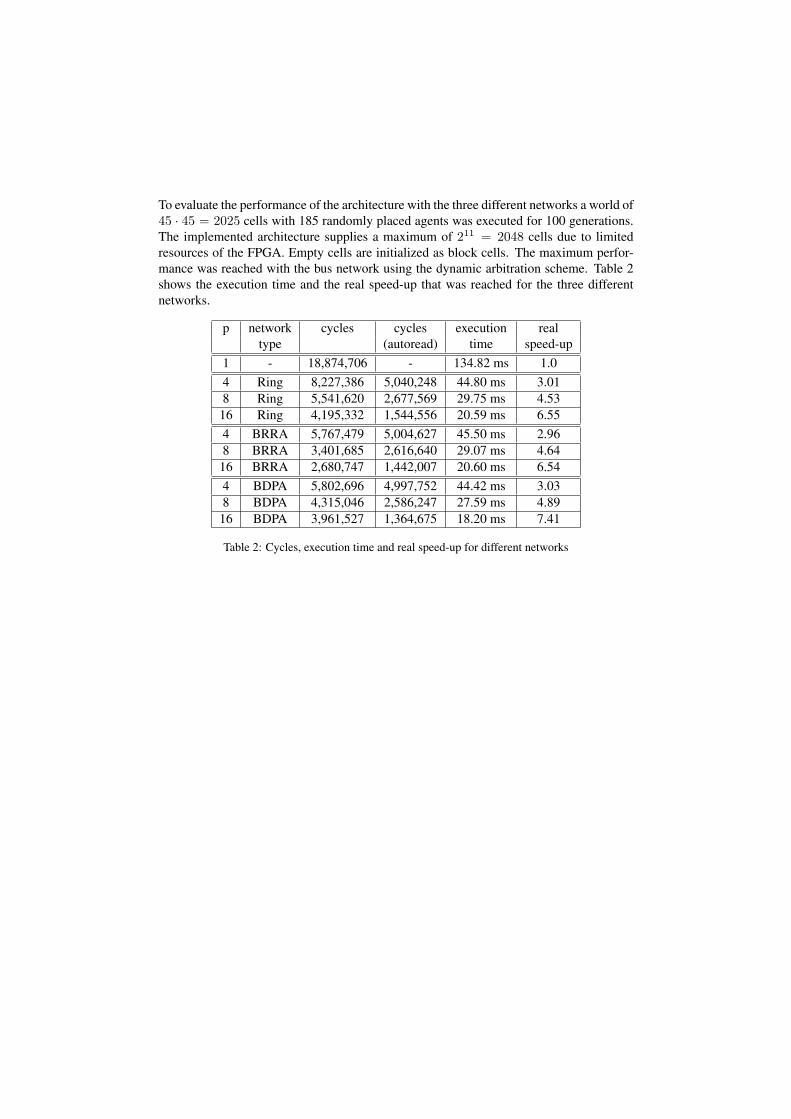
To evaluate the performance of the architecture with the three different networks a world of45 · 45 = 2025 cells with 185 randomly placed agents was executed for 100 generations.The implemented architecture supplies a maximum of 211 = 2048 cells due to limitedresources of the FPGA. Empty cells are initialized as block cells. The maximum perfor-mance was reached with the bus network using the dynamic arbitration scheme. Table 2shows the execution time and the real speed-up that was reached for the three differentnetworks.
p network cycles cycles execution realtype (autoread) time speed-up
1 - 18,874,706 - 134.82 ms 1.04 Ring 8,227,386 5,040,248 44.80 ms 3.018 Ring 5,541,620 2,677,569 29.75 ms 4.53
16 Ring 4,195,332 1,544,556 20.59 ms 6.554 BRRA 5,767,479 5,004,627 45.50 ms 2.968 BRRA 3,401,685 2,616,640 29.07 ms 4.64
16 BRRA 2,680,747 1,442,007 20.60 ms 6.544 BDPA 5,802,696 4,997,752 44.42 ms 3.038 BDPA 4,315,046 2,586,247 27.59 ms 4.89
16 BDPA 3,961,527 1,364,675 18.20 ms 7.41
Table 2: Cycles, execution time and real speed-up for different networks
4.2 Network Evaluation
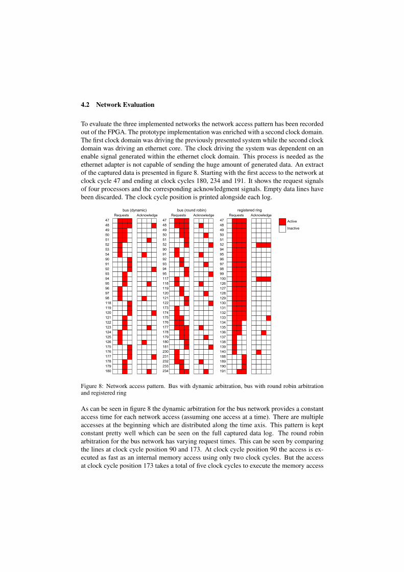
To evaluate the three implemented networks the network access pattern has been recordedout of the FPGA. The prototype implementation was enriched with a second clock domain.The first clock domain was driving the previously presented system while the second clockdomain was driving an ethernet core. The clock driving the system was dependent on anenable signal generated within the ethernet clock domain. This process is needed as theethernet adapter is not capable of sending the huge amount of generated data. An extractof the captured data is presented in figure 8. Starting with the first access to the network atclock cycle 47 and ending at clock cycles 180, 234 and 191. It shows the request signalsof four processors and the corresponding acknowledgment signals. Empty data lines havebeen discarded. The clock cycle position is printed alongside each log.
Figure 8: Network access pattern. Bus with dynamic arbitration, bus with round robin arbitrationand registered ring
As can be seen in figure 8 the dynamic arbitration for the bus network provides a constantaccess time for each network access (assuming one access at a time). There are multipleaccesses at the beginning which are distributed along the time axis. This pattern is keptconstant pretty well which can be seen on the full captured data log. The round robinarbitration for the bus network has varying request times. This can be seen by comparingthe lines at clock cycle position 90 and 173. At clock cycle position 90 the access is ex-ecuted as fast as an internal memory access using only two clock cycles. But the accessat clock cycle position 173 takes a total of five clock cycles to execute the memory access
adding three wait cycles for the arbitration. This shows clearly the round robin executionbehavior. As can be seen from this short data log extract the dynamic arbitration is fasterfor single accesses to the bus network. Comparing the first lines also shows the differentpriorities of the arbitration, although the round robin arbitration could show a differentpattern depending on the time of the network access and the status of the arbiter. Taking alook at the registered ring network shows that it is faster than the round robin but slowerthan the dynamic arbitration on the bus network. This does not apply to the overall per-formance. In contrast to the bus network the ring network executes multiple requests at atime. The acknowledgment data at clock cycle position 52 shows this behavior. The firstaccesses need six clock cycles which is the best performance that can be reached. Fourclock cycles are needed for the request and the acknowledgment to move around the ringand two clock cycles are needed for the actual request. The following requests take moreclock cycles indicating additional wait cycles due to an occupied ring.
5 Conclusion
The implemented multi-core architecture is very flexible because different agent behav-iors can be programmed and run on the same architecture. The network has a large impacton the performance and the bus system with dynamic arbitration showed the best perfor-mance. This performance can further be improved by new custom instructions separatingthe network read request from the network reply. This gives the processor the ability tocontinue with the program execution instead of being stalled. Although the present archi-tecture is very flexible only one link and one data field of the GCA model are supported.Future implementations will support multiple link and data fields providing the ability tostore multiple data for each cell. This can be used to run intelligent agents more efficientlyby storing additional values in separate data fields.
References
[Alt06] Altera, Datasheet Cyclone II.http://www.altera.com/literature/hb/cyc2/cyc2_cii5v1.pdf,2006.
[Alt09] Altera, NIOS II Website.http://www.altera.com/products/ip/processors/nios2/ni2-index.html, 2009.
[DJT01] J. Dijkstra, J. Jessurun, and Harry J. P. Timmermans. A Multi-Agent Cellular Au-tomata Model of Pedestrian Movement. In M. Schreckenberg and S. D. Sharma, edi-tors, Pedestrian and Evacuation Dynamics, pages 173–181. Springer, 2001.
[FS05] Dietmar Fey and Daniel Schmidt. Marching-pixels: a new organic computing paradigmfor smart sensor processor arrays. In Nader Bagherzadeh, Mateo Valero, and AlexRamırez, editors, Conf. Computing Frontiers, pages 1–9. ACM, 2005.
[HVW00] Rolf Hoffmann, Klaus-Peter Volkmann, and Stefan Waldschmidt. Global cellular au-tomata GCA: an universal extension of the CA model, 2000.
[HVWH01] Rolf Hoffmann, Klaus-Peter Volkmann, Stefan Waldschmidt, and Wolfgang Heenes.GCA: Global Cellular Automata, A Flexible Parallel Model, 2001.
[KEFH09] Marcus Komann, Patrick Ediger, Dietmar Fey, and Rolf Hoffmann. On the Effective-ness of Evolution Compared to Time-Consuming Full Search of Optimal 6-State Au-tomata. In Leonardo Vanneschi, Steven Gustafson, Alberto Moraglio, Ivanoe De Falco,and Marc Ebner, editors, Genetic Programming, pages 280–291. Springer, 2009.
[Klu01] Franziska Klugl. Multiagentensimulation: Konzepte, Werkzeuge, Anwendungen.Addison-Wesley Verlag, 2001.
[KSH07] Ari Kulmala, Erno Salminen, and Timo D. Hamalainen. Evaluating Large System-on-Chip on Multi-FPGA Platform. In S. Vassiliadis et al., editor, International Work-shop on Systems, Architectures, Modeling and Simulation (SAMOS), pages 179–189.Springer, 2007.
[RSM01] Kyeong Keol Ryu, Eung Shin, and Vincent J. Mooney. A Comparison of Five DifferentMultiprocessor SoC Bus Architectures. In DSD ’01: Proceedings of the EuromicroSymposium on Digital Systems Design, pages 202–209, Washington, DC, USA, 2001.IEEE Computer Society.
[SHH09a] Christian Schack, Wolfgang Heenes, and Rolf Hoffmann. A Multiprocessor Archi-tecture with an Omega Network for the Massively Parallel Model GCA accepted onSAMOS-Workshop, 2009.
[SHH09b] Christian Schack, Wolfgang Heenes, and Rolf Hoffmann. Network Optimization ofa Multiprocessor Architecture for the Massively Parallel Model GCA. In 22. PARSWorkshop, Gesellschaft fur Informatik (GI), 2009. ISSN 0177-0454.
[Ung97] Theo Ungerer. Parallelrechner und parallele Programmierung. Spektrum Akademis-cher Verlag, Heidelberg, Berlin, 1997.
[Wei02] Alan R. Weiss. Dhrystone Benchmark - History, Analysis, ”Scores” andRecommendations. http://www.ebenchmarks.com/download/ECLDhrystoneWhitePaper.pdf, 2002.