gas exchange in internalcombustionengines · gas exchange in combustionengines7. & 8. nov 2007...
TRANSCRIPT

Gas Exchange in Combustion Engines 7. & 8. Nov 2007 | Page 1 / 20
Gas Exchange in Internal Combustion Engines
Gas Exchange in Combustion Engines 7. & 8. Nov 2007 | Page 2 / 20
Accurate determination of important gas exchange parameters directly at the test bed based on existing measured
values
Dr. Robert Fairbrother, development simulation GCADipl.-Ing. Fernando Moreno Nevado, development gasoline engines,
Dr. Thomas Leifert, product management GCA
AVL List GmbH
Gas Exchange in Combustion Engines 7. & 8. Nov 2007 | Page 3 / 20
AVL GCA
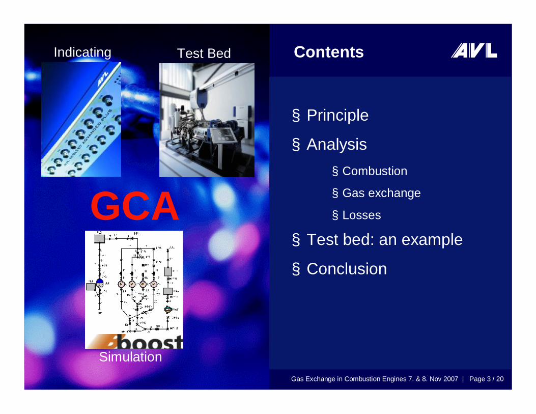
Simulation
Test Bed
GCA
Contents
§ Principle
§ Analysis§ Combustion
§ Gas exchange
§ Losses
§ Test bed: an example
§ Conclusion
Indicating
Gas Exchange in Combustion Engines 7. & 8. Nov 2007 | Page 4 / 20
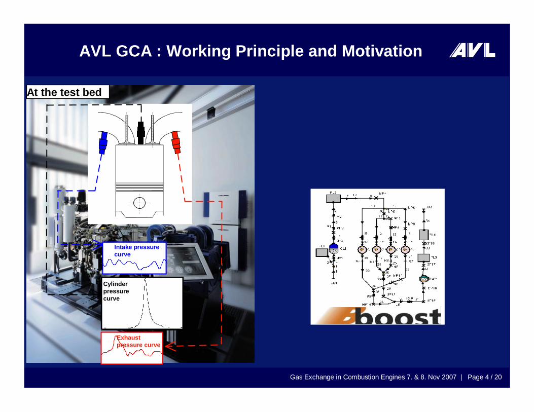
AVL GCA : Working Principle and Motivation
At the test bed
Exhaustpressure curve
Intake pressurecurve
Cylinderpressurecurve
Gas Exchange in Combustion Engines 7. & 8. Nov 2007 | Page 5 / 20
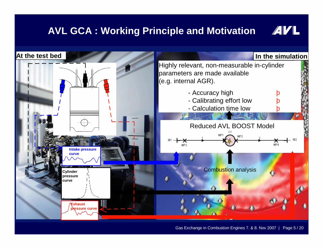
At the test bed In the simulation
Reduced AVL BOOST Model
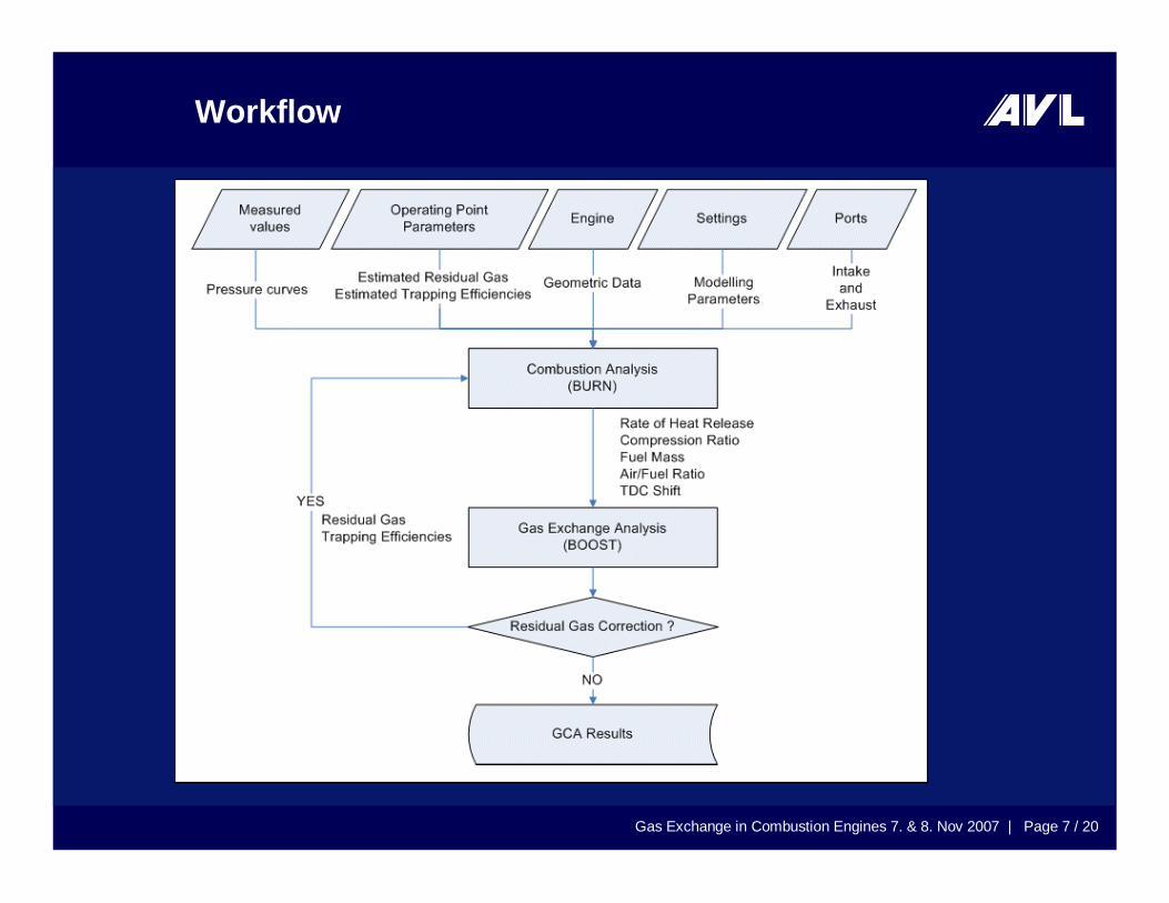
Combustion analysis
Highly relevant, non-measurable in-cylinderparameters are made available(e.g. internal AGR).
- Accuracy high þ- Calibrating effort low þ- Calculation time low þ
Exhaustpressure curve
Intake pressurecurve
Cylinderpressurecurve
AVL GCA : Working Principle and Motivation
Gas Exchange in Combustion Engines 7. & 8. Nov 2007 | Page 6 / 20
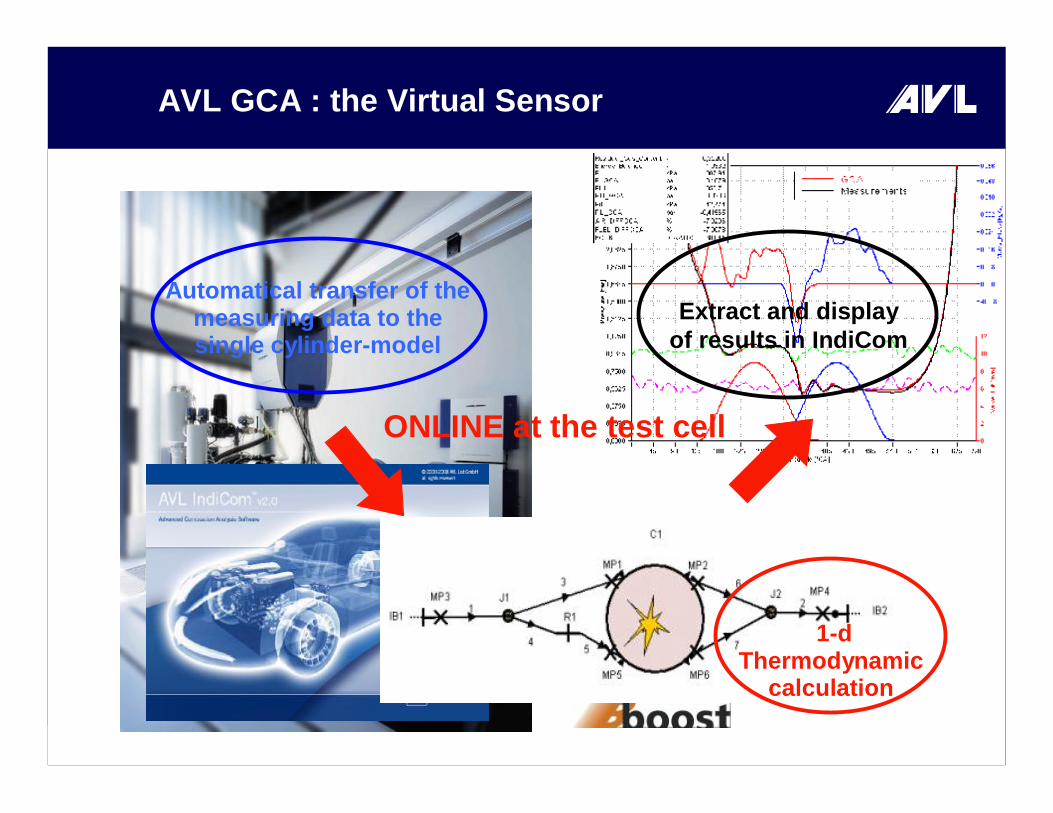
AVL GCA : the Virtual Sensor
É
Extract and displayof results in IndiCom
ONLINE at the test cell
Ç
1-d Thermodynamic
calculation
Å
Automatical transfer of the measuring data to the single cylinder-model
Gas Exchange in Combustion Engines 7. & 8. Nov 2007 | Page 7 / 20
Workflow
Gas Exchange in Combustion Engines 7. & 8. Nov 2007 | Page 8 / 20
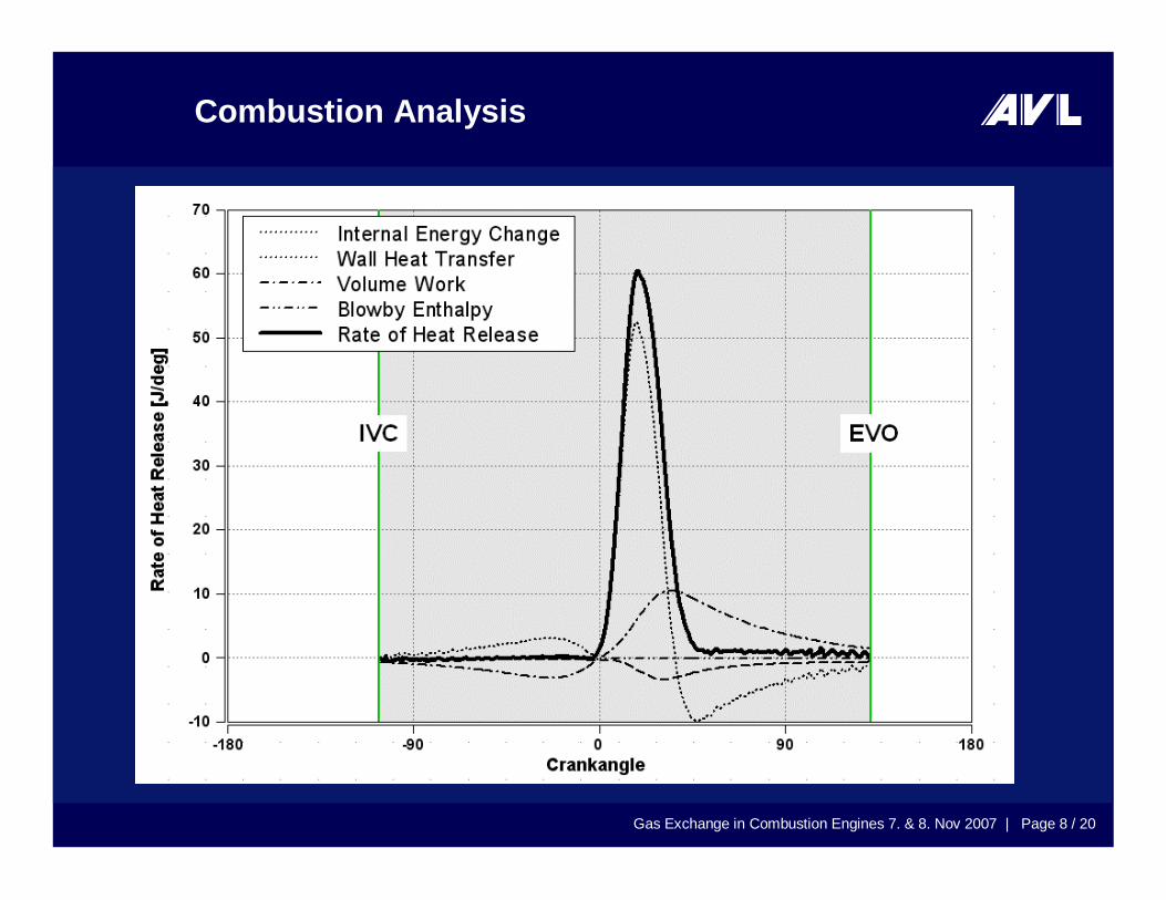
Combustion Analysis
Gas Exchange in Combustion Engines 7. & 8. Nov 2007 | Page 9 / 20
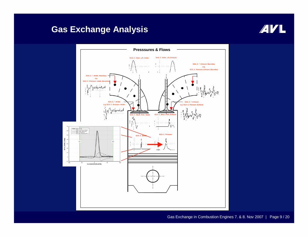
GCA_C_*_Exhaust_Boundarye.g.
GCA_C_Pressure_Exhaust_Boundary
BURN_C_ROHR
(Only values after start of combustion areused and are normalized by BOOST) GCA_C_ROHR
GCA_C_Pressure
GCA_C_Valve_Lift_ExhaustGCA_C_Valve_Lift_Intake
GCA_C_Mass_Flow_Intake GCA_C_Mass_Flow_Exhaust
GCA_C_*_Intake_Boundarye.g.
GCA_C_Pressure_Intake_Boundary
GCA_C_*_Intake
e.g. GCA_C_Pressure_IntakeGCA_C_*_Exhaust
e.g. GCA_C_Pressure_Exhaust
Presssures & Flows
Gas Exchange Analysis
Gas Exchange in Combustion Engines 7. & 8. Nov 2007 | Page 10 / 20
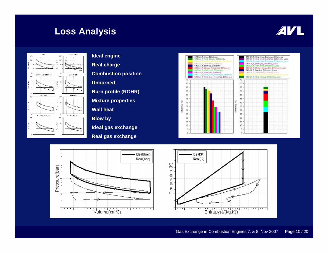
Loss Analysis
Ideal engine
Real charge
Combustion position
Unburned
Burn profile (ROHR)
Mixture properties
Wall heat
Blow by
Ideal gas exchange
Real gas exchange

Gas Exchange in Combustion Engines 7. & 8. Nov 2007 | Page 11 / 20
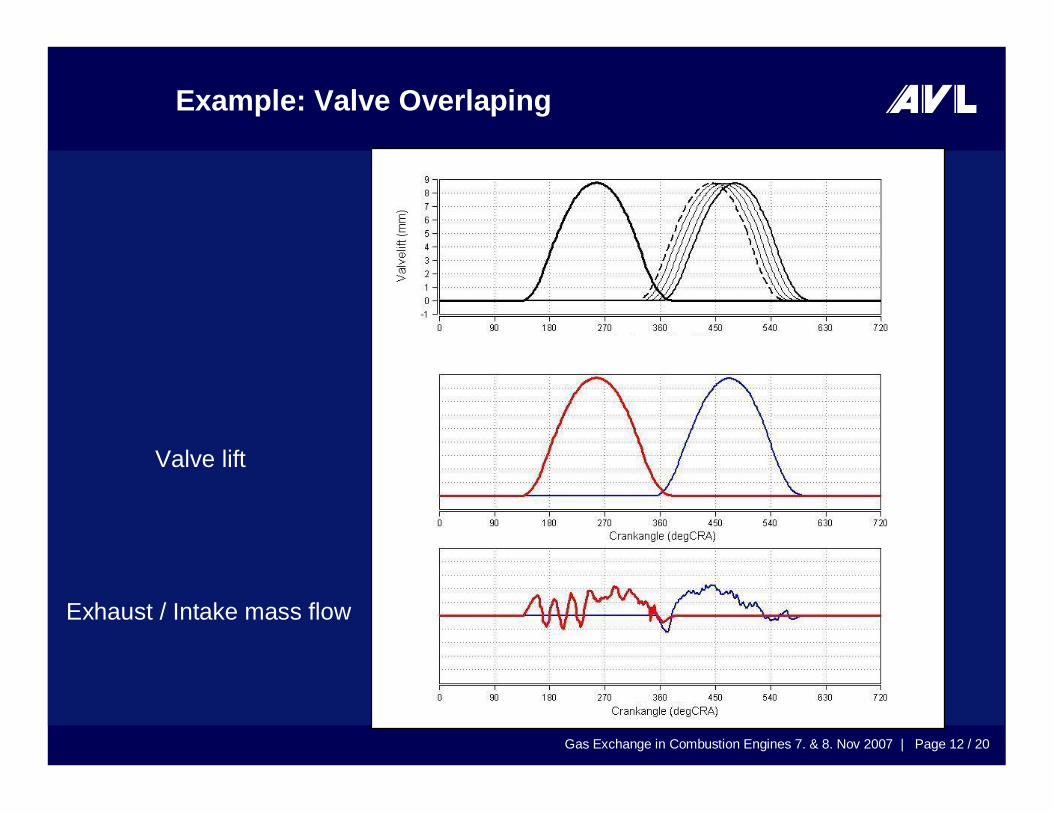
Example: Valve Overlaping
Exhaust / Intake mass flow
Valve lift
Gas Exchange in Combustion Engines 7. & 8. Nov 2007 | Page 12 / 20
Example: Valve Overlaping
Exhaust / Intake mass flow
Valve lift

Gas Exchange in Combustion Engines 7. & 8. Nov 2007 | Page 13 / 20
Example: Valve Overlaping
Exhaust / Intake mass flow
Valve lift

Gas Exchange in Combustion Engines 7. & 8. Nov 2007 | Page 14 / 20
Example: Valve Overlaping
Exhaust / Intake mass flow
Valve lift

Gas Exchange in Combustion Engines 7. & 8. Nov 2007 | Page 15 / 20
Example: Valve Overlaping
Exhaust / Intake mass flow
Valve lift
Gas Exchange in Combustion Engines 7. & 8. Nov 2007 | Page 16 / 20
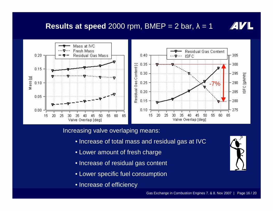
Results at speed 2000 rpm, BMEP = 2 bar, λ = 1
Increasing valve overlaping means:
• Increase of total mass and residual gas at IVC
• Lower amount of fresh charge
• Increase of residual gas content
• Lower specific fuel consumption
• Increase of efficiency
-7%
Gas Exchange in Combustion Engines 7. & 8. Nov 2007 | Page 17 / 20
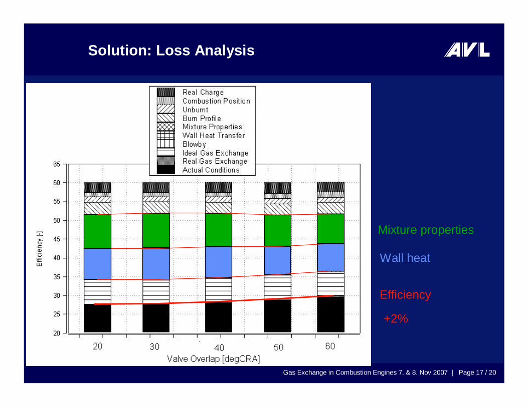
Solution: Loss Analysis
Wall heat
Mixture properties
Efficiency
+2%

Gas Exchange in Combustion Engines 7. & 8. Nov 2007 | Page 18 / 20
Wall Heat Loss
Gas Exchange in Combustion Engines 7. & 8. Nov 2007 | Page 19 / 20
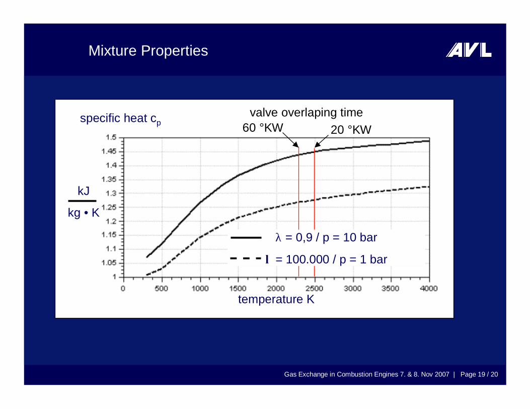
Mixture Properties
20 °KW60 °KW specific heat cp
λ = 0,9 / p = 10 bar
λ = 100.000 / p = 1 bar
temperature K
kJ
kg • K
valve overlaping time
Gas Exchange in Combustion Engines 7. & 8. Nov 2007 | Page 20 / 20
Conclusion
Accurate determination of important gas exchange parametersdirectly at the test bed based on existing measured values
2%
AVL-GCA