an investigation into piston ring blowby and its …
TRANSCRIPT

AN INVESTIGATION INTO PISTON RING BLOWBYAND ITS EFFECT ON BIOGAS ENGINES.
Graham Peter Bush BSc (Hons), MRSC
Thesis submitted in partial fulfilment of the requirements for Doctorof Philosophy of the Council for National Academic Awards.
School of Mechanical and production EngineeringSchool of Chemistry
Leicester Polytechnic.
October 1986

AN INVESTIGATION INTO PISTON RING BLOWBYAND ITS EFFECT ON BIOGAS ENGINES.
Graham Peter Bush BSc (Hons), CChem, MRSC
October 1986
ABSTRACTThis study has investigated the severe corrosion of Biogas engines bythe blowby gases. The formation of blowbYt its composition andflowrate have been measured and simulated. The nature of the pistonring sealing, lubrication and breakdown has been examined.
A study of Biogas engines showed that Copper corrosion of the smallend and camshaft bearings by HZS gas was the reason for enginefailure. H2S is present in all Biogas at a concentration ofusually less than 1%, but succeeds in chemical attack despite itsgood combustion properties, and the expected reaction with the basespresent in the lubrication oil. The HZS was corroding in itsgaseous state, but only those bearings with indirect lubrication.The solution to this problem is either to adopt force fed lubricationof the bearings, or to replace the alloy with Aluminium-Tin.
The experimental work used four engines of differing wear. Theconstant speed work showed that the fuel content of blowby gasincreases with load despite any increase in fuelling rate. Thistrend was consistent for all gaseous fuels present including H2S.
A series of computer calculations of piston ring blowby werecompleted, using conventional and novel input data. The resultantblowby flow was within an order of magnitude, confirming that twoblowby mechanisms, ring gap blowby and ring seal breakdown, arepresent on worn engines. The composition results showed that thefuel content of blowby is subject to the complex nature of thequenching process in the combustion chamber.
A study of the oil present at the top ring showed that the oil isgreatly modified when compared with the sump oil, as a result ofthermal degradation and base depletion. The oil has a high acid TAN,which suggests it could encourage corrosive wear of the cylinderliner.

ACKNOWLEDGEMENTS
I would like to express my gratitude to my supervisors, Professor D J
Picken and Dr M F Fox for their guidance and encouragement throughoutthe course of the research.
I would like to thank Mr L A Tibbs, Mr C English and Mr R J Smith fromthe School of Mechanical and Production Engineering, and Mr C Grovesand Mr R White from the School of Chemistry for their technicalassistance.
I would like to thank Dr D A Armitage for his lively debate.
I am indebted to the SERC for financing a research assistantship.
I would like to thank the following organisations for their assistance:
Anglian Water AuthorityApplied Energy SystemsAustin Rover GroupBrooksby Agricultural CollegeEsso Chemicals, AbingdonFord Motor CompanyMQAD, HarefieldPerkins engine companypowertorque, CoventrySevern-Trent Water AuthorityVilliers Limited
Finally to my wife Sarah, for her assistance in preparing this thesis.

To my Parents

CONTENTS PAGE
Chapter 1 Introduction. 8
1.1 World Energy.
1.2 Biotechnology.
1.2.1 The bioenergy conversion technologies.
1.2.2 The history of Biogas.
1.2.3 The principles of Biogas production.
1.2.4 The Nature of Biogas.
1.2.5 Gaseous fuels in internal combustion engines.
8
10
10
12
12
15
16
18
19
1.3 Project Aims.
References for Chapter 1, Tables and Figures.
Chapter 2 Analysis of failures and experimental engine work. 26
2.1 Introduction.
2.1.1 Corrosion in Biogas engines.
2.1.2 Biogas and crankcase gas in engines.
2.2 Experimental.
2.2.1 Objectives.
2.2.2 Experimental Technique.
2.3 Results using Methane.
2.4 Experimentation using H2S in the fuel.
2.4.1 Equipment modifications.
2.4.2 Results using H2S.
2.5 Discussion of Experimental Results.
References for Chapter 2, Tables and Figures.
26
26
38
41
41
43
46
49
49
51
52
63
5

Chapter 3 An investigation of the mechanism of blowby. 98
3.1 Introduction.
3.2 The Static Piston Experiment.
3.2.1 Experimental.
3.2.2 Results and Calculations.
3.2.3 Curve fitting of static blowby data.
3.3 Measurement of Pressure - Crank angle diagrams.
3.3.1 Experimental.
3.3.2 Calculations.
3.4 Calculation of blowby flowrate and composition.
3.4.1 Flowrate calculation.
3.4.2 Calculation of blowby composition.
3.5 Discussion of computed results.
References for Chapter 3, Tables and Figures.
98
101
101
102
105
107
107
107
109
109
112
ll9
126
Chapter 4 The Investigation of oil in the top ring zone. 149
4.1 Introduction.
4.1.1 Lubricating oil and crankcase gas.
4.1.2 The mechanism of cylinder liner lubrication.
4.2 Experimental.
4.3 Results and discussion.
References for Chapter 4, Tables and Figures.
149
149
153
156
159
165
6

Chapter 5 Discussion. 172
5.1 Conclusions from the study of blowby gas.
5.2 The use of small engines in the Biogas Industry.
5.3 Conclusions from the study of top ring oil.
5.4 Recommendations and further work.
References for Chapter 5, Tables and Figures.
172
174
176
177
178
Appendix 1 Computer listings and explanations.
7

Chapter 1. Introduction.
1.1 World Energy.
The sharp rise in crude oil prices in the early 1970's highlightedour dependence upon oil as the major source of energy, and wasresponsible for increased public interest in energy conservation andresearch. Statistical studies of present and future energy use andreserves, both worldwide and nationally, show that conventionalenergy sources will only sustain our energy needs for a finite time(the decline in oil production is predicted to be at approximatelythe year 2000). Table 1.1 shows a recent estimate of current andfuture world energy use. Such forecasts are constantly updated astechnological and economic changes alter energy production andconsumption patterns, and have, in the past, been inaccurate.However, all forecasts anticipate energy demand outstripping futureenergy provision by the oil industry. They clearly indicate theimmediate need for research and development into alternative sourcesof energy.
The distribution of energy resources and their use variesconsiderably from one country to another. The industrialised nationshave a high per capita consumption of high grade energy (e.g.electricity, gas and petroleum distillates). Fig 1.1 shows thepattern of U.K energy use over the last 35 years. The intelligentuse of conservation measures within these communities is likely toproduce an effective reduction in total world energy consumption (Ref1.1). These nations also have the technological base from whichconservation industries can grow, coupled with a large stablepopulation who readily accept energy saving measures. However, thehigh degree of industrialization and large domestic market ensures ahigh demand for electricity in the future. Both established andnovel alternative energy industries can compete in the market tosupply electricity provided that the unit cost of its production iscompetitive with that of other technologies being developed toreplace oil based power supplies.
8

In contrast, the developing countries depend on lower grade fuels,which are mainly used for cooking and heating. It has been suggested(Ref 1.2) that the shortage of firewood and the consequentdefoliation of woodland and forest areas constitutes a larger andmore difficult energy problem than the future decline in oilproduction. The developing countries are also experiencing a massiveincrease in population, which shows no signs of easing in thefuture. These two factors, combined with the commitment bygovernments to improve. the living standards of their people, willgenerate an increasing energy demand in these countries. Oneimportant feature is common to most developing nations - a relativelylow population density. This factor, combined with poor'communications, promotes localised energy provision; national energypolicies are poorly developed and those that exist are notparticularly ambitious. Hence, conservation measures must also be ona localised basis, and this makes it harder to achieve large overallsavings. However, the widespread use of alternative energy sourcespromises to provide a viable means of future supply because they canbe tailored to suit local requirements. The large areas of availableland space, the generally favourable climate and the need forsmall-to-medium sized installations are well suited to novel energytechnologies, particularly those which are solar based.
It has been estimated that the annual solar radiation reaching theearth's surface has an energy content of 3 x 1024 J, which isequivalent to 75 times the world's proven fossil fuel reserves. Ofthis, 60% is available for absorption by plants, and 0.1% is actuallycollected by plant photosynthesis (Ref 1.3). Although the energy ofthe solar radiation reaching the earth's surface is dispersed, thetrapping of sunlight, particularly in the otherwise unpopulateddesert regions, is expected to be one of the major sources ofelectricity in the future. Research in several nations, notably theUSA, has been undertaken into the direct use of sunlight to powersteam turbines at desert based power stations (Ref 1.4).
9

Major solar energy projects, using the sun as a "primary" source,have been very successful in attracting finance for theirdevelopment. The direct trapping and conversion of light energy iswell suited to smaller scale installations (es g domestic water andspace heating) and shows potential with solar cells.
Supplementing these applications are the "secondary" solartechnologies such as hydro-electric or wind power. These are wellestablished techniques which are being tailored to suit modernneeds. Several biological energy conversion technologies are alsocurrently under development. As with other solar based energyprojects they benefit from the virtually unlimited supply from thesun (via photosynthesis), simple technology, and also from a publiclyapproved ecological image. Along with geophysical projects such asgeothermal power or hydro-electricity, biotechnology is renewable,promising potential long after the exhaustion of mineral supplies.However, the application is less advanced, with a few successfulprojectsdigestion
such as alcohol automotive fuel in Brazil or anaerobicof animal wastes' in India and China. Such projects
illustrate that Biotechnology could become a very important source ofenergy because it can directly replace petroleum in its two majorfunctions; motor f~el and chemical feedstock (Ref 1.4). There' aremany experimental biotechnology based proposals whose aim is to provethat they are viable and capable of a positive contribution towardsfuture world energy needs. Only then will these proposals attractthe financial backing required to exploit their potential.
1.2 Biotechnology.
1.2.1 The Bioenergy Conversion Technologies.
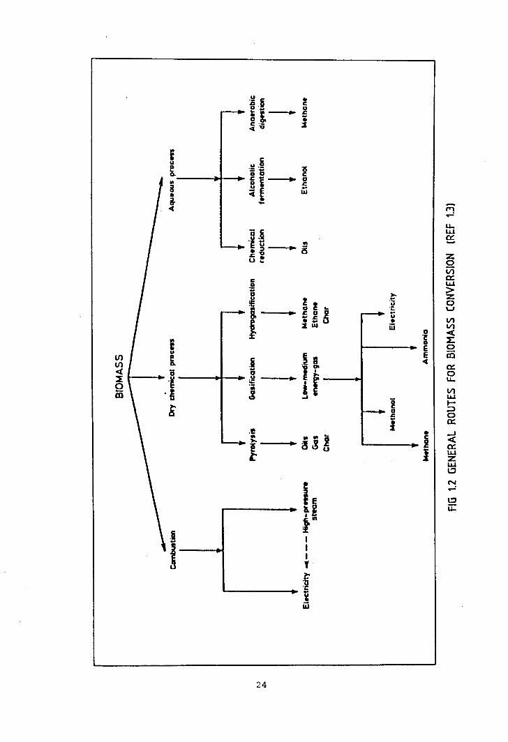
Fig 1.2 shows the general routes for the conversion of Biomass intohigh grade fuels or electricity. The application of, or researchinto, these areas is largely dependent on localised factors such asthe availability of feedstock or the energy needs of the user. Thefeedstock, Biomass, is a variable material as it is dependent on
10

local climate, agricultural and industrial techniques, and alsogeographical conditions. The product generated is applied to satisfyspecific needs, which depends on the society, climate and geographyof the user. Therefore the development of a given Biotechnology willvary across the world.
This project is associated with the Leicester Polytechnic AnaerobicDigester Group's research into the anaerobic digestion of animalwastes. The anaerobic digestion of biomass is a long establishedprocess, as outlined in Section 1.2.2. The product "Biogas" containsCH4 and CO2 in roughly a 2:1 ratio, with up to 1% of H2S andother trace gases such as H2 and N2 (see Section 1.2.4). Theanaerobic digestion process is very tolerant to the type offeedstock, being able to produce Biogas from a very wide variety ofnatural materials. These range from sewage and animal excreta toplant matter (e.g water hyacinth, grass, algae) and industrial wastes(e.g brewery hops, paper sludge, cheese whey). On industrial sites,digestion is often used as a treatment step to break down anunpleasant effluent before disposal. It is often a viable processfor this reason alone, as pollution control legislation can besatisfied by the anaerobic breakdown of the waste. Under thesecircumstances, the production of Biogas is an additional bonus, whichcan be used to contribute towards the energy needs of the treatmentplant concerned.
Considerable research has been undertaken into the development ofimproved digestion technology and efficient gas output, with wideapplication to all sizes of digester. However, the utilisation ofthe gas produced always depends upon the needs of the individualsite. As a result, digester design has been improved by bothindustrial and research projects, but the development of thetechnology to exploit the gas produced has remained site dependent.The lack of co-ordinated development of the gas utilisationtechniques has had an important effect on the commercial developmentof the smaller scale digester, because its viabl1ity relies on theeffective use of the gas produced.
11

1.2.2 The History of Biogas.
The production of marsh gas has been observed throughout history and
is the simplest natural form of anaerobic digestion. The anaerobic
breakdown of natural materials occurs in all de-oxygenated
environments including lagoons, peat bogs, marshes and swamps. It
has been estimated that natural sources produce at least ten times as
much H2S as man does. This occurs as a result of both anaerobic
digestion and volcanic activity (Ref 1.5). Investigations of "air
produced by substances putrefying in water" began as early as 1790
(Ref 1.6).
The first artificial digesters were sewage lagoons, created during
the Industrial Revolution, where the effluent was left to process
naturally. The subsequent increase in population, combined with
increased technical knowledge, led to the development of more
advanced systems for the processing of sewage sludge. The first
known use for Biogas was for gas street lighting in Exeter in 1896
(Ref 1. 7) • This marked the start of the development of unheated
sludge digesters. By the 1920's these digesters were becoming
overloaded, and the' heated digester was conceived. This development
reduced the process retention time. Subsequent research was directed
towards the refinement of this technique, and it was not until the
1950' s that the "high rate" digesters were introduced. It is only
recently that concerted research has begun to understand and refine
the digestion process itself, although this is unlikely to produce a
significant improvement in the rate of gas production. However, the
emphasis has moved away from effluent treatment alone, and towards
optimizing the production and utilisation of Biogas.
1.2.3 The Principles of Biogas Production.
Anaerobic digestion is the bacterial breakdown of organic molecules.
It has been used to produce Biogas from a wide variety of natural
materials, with varying degrees of success (Ref 1.3). The great
12

advantage of this process is that it occurs spontaneously once theanaerobic conditions have been established, as the bacteria arealready present in the slurry mixture. The processing costs aretherefore very low, the largest cost being the heat to keep theslurry temperature within the optimum range 300c to 400C (theprocess does not generate enough heat to counteract both the heatloss from the digester and also that incurred due to slurryreplacement). The heat input required varies with both the localclimate and seasons. This favours the operation of digesters intropical or sub-tropical regions of the world where there is littleseasonal temperature variation around a warm mean value.
The process by which methane is formed appears to involve threeinterdependent metabolic groups of bacteria; fermentative, H2producing acetogenic, and methanogenic (Ref 1.8). The role of afourth group, the H2-consuming acetogenic bacteria, is stillunclear, but they do not make a major contribution to the digestionprocess (Ref 1.9)• A schematic reaction is given in Fig. 1.3, butthe exact mechanisms are still largely unknown, mainly due to thelarge variety of participant species and the complex interdependenceof various types on one another. However, within the digester.environment, the catabolism of organic plant matter forms a foodchain, with each group using the breakdown products from the last.
The fermentative bacteria are responsible for the breakdown oforganic materials into carboxylic acid salts, H2, CO2 and otherproduct molecules. The concentration of H2 in solution is criticalto the amount of acetate produced; at higher H2 concentrations,longer chain carboxylic acids are the favoured products.
The H2-producing acetogenicproduction of acetate, H2
bacteria are responsible for theand CO2 from the longer chain
carboxylic acids, alcohols and other organic acids which are formedas part of the first stage fermentation. A low H2 concentration inthe solution is critical for these reactions to occur.
13

The methanogenic bacteria catabolise the acetate and CO2 into CH4using the H2 produced by the other two metabolic groups, but thisgroup can only perform the methanogenesis under strictly anaerobicconditions. The rapid consumption of the H2 controls the othersteps in the digestion process, and the activity of the methanogenicbacteria acts as a regulatory mechanism for the complete digestionprocess.
The formation of H2 in solution is essentially a reduction of free+H during the first two stages of the digestion process. The
formation of H2S has been attributed to the reduction of dissolvedsulphate under these conditions (Ref 1.8). The sulphide produced isan important source of sulphur for all of the bacteria present.
The conditions under which anaerobic digestion occurs are welldocumented, and a considerable amount of research has been directedtowards the refinement of digester design, resulting in the modernhigh rate digesters. Apart from the establishment of strictlyanaerobic conditions, there are several important factors to beconsidered for maximising the gas output from slurry digesters:
.(a) The temperature of the digester must be maintained in the range300C to 400C to encourage healthy methane production. Thisis easily achieved in warmer climates, but heating (often usingthe product Biogas) is usually required in the temperate zonesduring the winter. This is an important consideration, asduring the winter months the energy demand is highest, and theBiogas used for digester heating is effectively a diversion ofenergy output during this period.
(b) The retention time for the slurry should be between 10 and 30days, with some degree of mixing within the digester tohomogenise the newer and partially digested sludge. The extent,method and rate of mixing depends on the design of the digesterconcerned, and the optimised rate of sludge homogenisationdeveloped for that digester.
14

(c) In some digester designs, it is important to monitor the pH, thesolids content and other physical or chemical parameters onwhich the operation is dependent. Such process control isinconvenient on small scale farm digesters, where simplicity isan essential factor.
1.2.4 The Nature of Biogas
The composition of the Biogas produced from Anaerobic Digestersdepends upon both the digester design and its operating conditions,but mainly on the nature of the digested material. The methanecontent of Biogas is normally within the range of 60% to 70%, withthe pre-treated feedstocks (e.g pig slurry) providing the highestcontent. The balance is carbon dioxide, with traces of H2, N2and H2S.
The analysis of Biogas is now a routine measurement by GasChromatography. An extensive programme of research by Grune andChueh (Ref 1.10) established the technique using column packingmaterials commonly available in the early 1960's. The refinement ofgas chromatographic analysis from this period onwards has yieldedimproved and specialised column packings, which give increasedcomponent resolution. Burgess and Wood (Ref 1.11) undertook a widerinvestigation of Biogas properties. Their work covered thecomposition, water content, explosion risk and a safety appraisal ofBiogas use in the sewage industry. This paper has been the basis formost of the analysis and handling techniques which have been devisedsince its publication. With the development of porous polymerchromatographic packings, their improved gas handling capabilitieswere quickly adopted for use with Biogas. A recent description ofBiogas analysis is presented in Warren Springs Laboratory WRC ReportTR85 (Ref 1.12).
The methane content of Biogas can vary considerably, but all Biogasis flammable and can be used to generate heat or power. The simplest
15

use for the gas is to produce heat for cooking, which is favoured inthe developing countries, where there is a constant need for thistype of low grade energy. The extensive anaerobic digesterprogrammes in India and China provide small scale digesters, whichyield Biogas to be used on a local basis for cooking. One of themajor advantages of direct heat use by burning the gas is thesimplicity of the technology involved with inherent low cost andminimal maintenance. However, in a more complex industrializedsociety, with centralized gas distribution, there are importantfailings in the use of biogas to supplement or replace existing gassources. The most fundamental problem is the quantity and qualityrequired of the gas supply. At best, Biogas can be envisaged as a"top up" supplement to the mains distribution system; in this countrythe demand for gas would drastically outstretch potential Biogasproduction. Raw Biogas is unsuitable for supplementing the mainssupply, first because of its inconsistent composition, and secondbecause of the potential corrosion and reliability problemsassociated with the introduction of H2S and water vapour into thegas mains. The gas would first require scrubbing (see Section2.2.1), drying and then compression and the processing costs involvedin this purification process would make the project unprofitable.These shortcomings 'rule out the use of Biogas as a direct source ofenergy within industrialized societies. The gas must either be usedon a localized basis, or its chemical energy must be converted intoanother form of energy.
1.2.5 Gaseous fuels in Internal Combustion Engines
The use of gaseous fuels in Internal Combustion engines is a wellestablished practice, the most common fuels being liquified Propaneand Methane. As such there is an established source of technology toprovide I.C engines tailored for use with Biogas. Such engines canbe used in two major areas; the production of power from staticengines, usually producing electricity and heat, or automotive use,supplementing or replacing conventional fuels.
16

The major constituent of both Biogas and Natural Gas is methane. Theuse of Natural Gas engines in static applications is common and theyare often used as a source of standby power. The use of LiquidNatural Gas (LNG) and Compressed Natural Gas (CNG) in automotiveapplications has gained support recently, because of the recent oilprice rises. CNG has been used in Italy for over 30 years (Ref1.14) , and is currently used in almost 200 000 vehicles (Ref 1.15).Recent development of CNG fuel networks have been undertaken, notablyin both the USA and New Zealand.
The motivation for these developments is the combination of low tocompetitive cost, and the very low pollution characteristics. Theuse of gaseous fuels enables a simpler design of induction system tobe used. The gas does not have to be vapourized, and therefore asimple gas mixing device can be used to combine the air and fuelprior to its entry into the combustion chamber. The efficiency ofmixing is very good, offering an even mixture distribution acrossmulti-cylinder engines (Ref 1.16).
There is a reduction, in theory, in the air breathing capacity whenusing methane fuel. This is because the fuel gas occupies a largervolume within the induced mixture than when a comparable atomizedliquid fuel is used. Methane also has a relatively slow flame speedwhen compared with gasoline. Both these factors could adverselyaffect the performance of a converted engine. These disadvantagescan be overcome by the optimization of the engine calibration(ignition timing, valve timing etc), and the excellent anti-knockcharacteristics of methane allow the use of very high compressionratio engines. The combustion of methane is highly efficient, givingvery low exhaust emissions, particularly for the CO and HC values.
17

1.3 Project Aims
The Biogas industry has been very successful in implementing largescale centralized digesters, with correspondingly large 1.C enginegeneration facilities. In contrast, the efficient use of the smallscale digester, producing useful power and heat, has not been fullyexploited.
The aims of this project were:
(a) To examine the type of engine design used with digesters, anddetermine why so many small scale digester projects suffer fromengine failures.
(b) To investigate the factors affecting the actual cause of failureand to propose solutions to the problem.
(c) To investigate the basic principals which affect the failuremechanism, and to determine the effect of differing stages ofengine wear.
18

References Chapter 1
1.1 BEIJDORFF A.F, Energy Efficiency publ. Shell International
Petroleum Co., 1979.
1.2 AUER P.L et a l., "Unconventional Energy Resources" in World
Energy Resources 1985 - 2020. pub1. IPC Scientific and Technical
Press 1978, pp 135 - 179.
1.3 SLESSER M, LEWIS C, Biological energy resources publ. E & F.N
Spon Ltd 1979.
1.4 RAHMER B.A, "Pue Ls for the fu ture " pub!. Petroleum Economist
1980 pp 41 - 49.
1.5 STRAUSSW, MAINWARINGS.J ··Air Pollution" pub!, Edward Arnold
1984 p 3.
1.6 PRIESTLEY J Experiments and observations on different kinds of
air Vol 1, (publ) Birmingham, 1790.
1.7 TIEJTEN C, ··From Biodung to Biogas - A historical review of the
european experience". Energy, Agriculture and Waste Management,
1980, pp 247 - 259.
1.8 McINERNEYM.J, BRYANTM.P, "Review of methane fermentation
fundament a l s" in WISE D (ed) Fuel gas production from Biomass Vol 1
CRCPress, 1983, pp 19 - 46.
1. 9 HAWKES F ··The biochemistry of anaerobic digestion·· in BUVETR,
FOX M.F, PICKEN D.J (eds) Biomethane, production and uses (publ)
Turret Wheatland 1984, pp 41 - 60.
1.10 GRUNE W.N, CHUEH C.F "Sludge gas analysis using Gas
Chromatography·· A report 1n 8 parts in Water and Sewage Works
December 1962 to July 1963.
19

1.11 BURGESS S.G, WOOD L.B "The properties and detection of sludgegas" J lnst Sew Purif 1964 pp 24 - 46.
1.12 Water Research Centre Report TR85, Warren Springs Laboratory,1980.
1.13 TISON R, SPRAFKA J et a1. "Safety issues surrounding the useand operation of CNG vehicles." SAE 831078.
1.15 JOYCE T.J "Research and deve Lopement; needs for CNG fuelledvehicles." SAE 831065.
1.16 KARIM G.A, WIERZBA I "Comparitive studies of Methane andPropane as fuels for S.I and C.I engines" SAE 831196.
1.17 Department of Energy Digest of United Kingdom energy statistics1985 HMSO pp 10 - 11.
1.18 FRANCIS W, PETERS M C "Fuels and Technology" (2nd Edn) PergamonPress p 473.
20

Figures Chapter 1.
Fig 1.1 Diagram of U.K energy consumption (Ref 1.17).
Fig 1.2 General routes for Biomass conversion (Ref 1.3)
.Fig 1.3 Schematic diagram of the digestion process (Ref 1.9)
Tables Chapter 1
Table 1.1 Current energy patterns in developed and underdevelopedcountries (Ref 1.18).
21

Energy Date Date Use Use Usesource of of in in world
90\ major third devel. widedepletion use world world
(>1\)
(A.D) (A.D) (1980) (1980) (2100)
VEGETABLE 75 2 21Food 30 2 9Food residues 25Wood 20Peat 2000Biomass 1990 8
FOSSIL 16 89 19Gas 2040 1940 2 12 1Oil 2020 1920 1 47 2coal 2500 1700 13 17 11Oil shale 2000 5
RENEWABLE 9 6 ·42Solar 1980 12Wind 1300 2 3Hydro 1000 7 6 3Wave 2000 5Tidal 1990 2Geothermal 2010 15Oceanic 2050 2
NUCLEAR Nil 3 18Thermal reactors 2050 1960 3 3Fast reactors 2000 14Fusion reactors 2050 1
TABLE 1.1 ENERGY PATTERNS IN DEVELOPED AND UNDERDEVELOPED COUNTRIES
22

r-..-;.-
0 u,CO Wa-0r- a::
z0t-o,l:.:::>Vlz
0 0~ t- U::> 0-ILl
0r- r_.0 L.:Jet:: a::I- wILl Z0-
W
~...J =>-c u,0'-' 0 0
-0a- l:«et::L.:J«CJ.-..-l.:J
0u,
U'l0-0-
0 0 0 00 0 0 0-1" ,." N 0-
IN31YAlnU3 1'10) SNOl NOl111W
23
iue0-Wl
~•&~
c.S!..D
~ !
!D ! ...I: " ~"I:...:aU.!
.Ii E
... .2 D
" I'"~
l !f.e
i
.B
J
itltIII,
___ fiin
24
o
IE~
zoVi0::L&.l>Zout/)t/)etl:oCO0::ou;t/)L&.lt-:::>o0::
--'et0::1J,JZL&.ll:JN~
Jj
l:Ju:

Polysaccharides, proteins
GROUP IHydrolytic andfermentatfvebacteria108-1 09cm- 3
acetate, H2• CO2, formate
propionatebutyrate
+long chain fatty acids,1 aromatic compounds
Group 11 Obligatehydrogen-producingacetogenic bacteria106 cm-3
acetate + H2 CO2 of. formate
Group IIIMethanogens106-108cm-3
Group IV Hydrogen-consuming acetogenic bacteria,10S-lOGcm-3
FIG 1.3 SCHEMA TIC DIAGRAM OF THE DIGESTION PROCESS.
25

Chapter 2 Analysis of failures and experimental engine work.
2.1 Introduction.
2.1.1 Corrosion in Biogas Engines.
The success of Biogas as an alternative energy source depends uponits ability to become a viable replacement for future conventionalsupplies. Central to this aim is the reliable production of Biogasand the continuity of electricity generation by engines running on afuel mixture containing H2S, which is very corrosive. In theindustrialized nations, the use of Biogas as a fuel forengine-generator sets producing electricity and heat has highlighteda reliability problem related to the size of engine used.
The large diesel dual-fuel (Diesel/Biogas) engines in municipalsewage works run very reliably with few, if any corrosion problems.This is partly due to the fact that sewage Biogas (at up to 0.1%H2S) is relatively low in H2S content compared to farm Biogas.The Thames Water Authority have Sewage digesters which have beenproducing electricity since the 1930's. In 1979/80, their sewage
.works produced over 9 x 10⁷ m3 of gas and their dual-fuelled210 MWh of electricity (Ref 2.1). In the
(Ref 2.2), Mogden sludge gas was quoted as0.05% H2S. At this concentration no
engines generated 1.26 xpaper by Burgess and Woodbeing between 0.02% andengine corrosion was reported.
A successful example of the municipal use of Biogas is theSevern-Trent Water Authority's Wanlip water reclamation works nearLeicester. Four large steel digester tanks with a total capacity of19093 m3 of sewage sludge are used to generate Biogas. In 1984,
3on average, a daily throughput of 1040 m of sewage sludge held3for 13.5 days, produced 12060 m of Biogas per day. The Biogas is
fed to five Harland and Wolf 860 bhp dual-fuelled diesel enginesinstalled in a purpose-built generator house. The engines annuallyproduce 10.2 x 10⁶ KWh of electricity which is approximately 80%
26

of total site usage. The cooling water from the engines is used toheat the digesters. The engines are regularly maintained with ashort service every 1,000 hours and a major overhaul and oil changeevery 20,000 hours. A recent 100,000 hour stripdown revealed thatthe small end bearing surfaces had no abnormal wear or Biogascorrosion (Ref 2.3). The Biogas at this site has between 0.15% and0.18% H2S content.
The large quantity of Biogas produced from this reclamation worksjustifies the massive investment in large marine derived engines.At smaller rural sewage works or on farms, the engines used must becorrespondingly smaller. These small scale digester engines sufferfrom extensive corrosion, particularly of copper-based bearingmaterials. Farm-sized digester engines are usually automotiveengines modified to run on gas, either as spark ignition ordual-fuelled diesel engines. Typically, the smallest biogas enginesare natural gas engines converted from automobile applications. Thepioneer commercial project in this area was the Fiat "Totem" systembased on their 903cc spark ignition engine. Similar conversionshave been done to the Ford Cortina OHC and Land Rover 2.2 11treengines. However, none of these have appeared in a corrosionresistant form, and consequently suffer failure when used withBiogas.
The STWA' s Retford sewage works has a small digester producingBiogas. This was fed to a Perkins G 4.236 gas engine installed in agenerating room adjacent to the gas holder. The engine ran for aperiod of just over two years, completing 9597 hours with the onlymajor shutdowns associated with ignition component development
4problems. During this period it annually produced 5.87 x 10 KWh4 3of electricity from 4.68 x 10 m of gas. Regular oil analysis
of the high TBN oil was performed. However, increasing engine noiseled to an engine stripdown and it was found that the phosphor-bronzesmall end bearings had suffered severe corrosion - in some partstotal disintegration. These bearings have recently been replacedand the manufacturer has consulted their bearing supplier (Glacier
27

Metals) to obtain an aluminium alloy alternative. The Biogas atthis site is high in H2S, within the range 0.35% to 0.40%. Thisconcentration is unusual for a sewage farm, and is in the rangenormally encountered at agricultural sites. The engine is now onstandby only, as the changes in CEGB tariffs have made it uneconomicto run (Ref 2.4).
The photographs (Figs 2.1, 2.3 - 2.6) show typical H2S corrosionof copper based bearings; in this case the camshaft bearing shellsfrom a Ford Dover dual-fuelled diesel engine (a "Powertorque"customized gas engine). The bearing surface has large areas ofsevere abrasion parallel to the direction of camshaft rotation (darkareas), interdispersed between regions of the original metal(lighter areas). The surface cross section A - D from Fig 2.1 wasmeasured by a Ta1ysurf and is shown in Fig 2.2. This clearly showsthat the damaged surface has been stripped of parent metal to leavea large trough containing the corrosion products. The scanningelectron micrographs (Figs 2.3 - 2.6) of the abraded region give adetailed view of the surface corrosion. The metal is initiallyattacked at weak points in its structure, and pitting occurs,leaving an uneven surface from which fragments flake away. Themovement of the camshaft, using these fragments suspended within theoil film, removes the upper layer of metal and corrosion products toreveal a fresh metal surface. This is then attacked by the H2S tocontinue the corrosion process. This mechanism is similar to thatfor the failure of small end bearings, where the combination of hightemperature, high bearing pressure and oil agitation (as a result ofthe cyclic movement of the piston) encourages the rapid corrosion ofthe copper alloy. This is similar to, but far more severe than, thecorrosion of bearing alloys observed at high temperatures withsulphurised oil additives (Ref 2.5).
The corrosion product, analysed by powder X Ray crystallography, isCopper Sulphide. This is a black solid whose appearance on allcopper and brass components is common at all Biogas installations.The corrosion of Copper by Sulphur compounds, including H2S, has
28
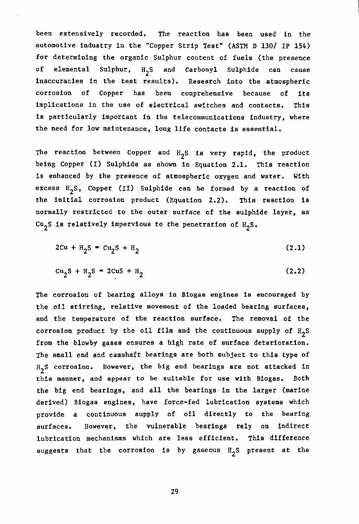
been extensively recorded. The reaction has been used in theautomotive industry in the "Copper Strip Test" (ASTM D 130/ IP 154)for determining the organic Sulphur content of fuels (the presenceof elemental Sulphur, H2S and Carbonyl Sulphide can causeinaccuracies in the test results). Research into the atmosphericcorrosion of Copper has been comprehensive because of itsimplications in the use of electrical switches and contacts. Thisis particularly important in the telecommunications industry, wherethe need for low maintenance, long life contacts is essential.
The reaction between Copper and H2S is very rapid, the productbeing Copper (I) Sulphide as shown in Equation 2.1. This reactionis enhanced by the presence of atmospheric oxygen and water. Withexcess H2S, Copper (II) Sulphide can be formed by a reaction ofthe initial corrosion product (Equation 2.2). This reaction isnormally restricted to the outer surface of the sulphide layer, asCu2S is relatively impervious to the penetration of H2S.
(2.1)
(2.2)
The corrosion of bearing alloys in Biogas engines is encouraged bythe oil stirring, relative movement of the loaded bearing surfaces,and the temperature of the reaction surface. The removal of thecorrosion product by the oil film and the continuous supply of H2Sfrom the blowby gases ensures a high rate of surface deterioration.The small end and camshaft bearings are both subject to this type ofH2S corrosion. However, the big end bearings are not attacked inthis manner, and appear to be suitable for use with Biogas. Boththe big end bearings, and all the bearings· in the larger (marinederived) Biogas engines, have force-fed lubrication systems whichprovide a continuous supply of oil directly to the bearingsurfaces. However, the vulnerable bearings rely on indirectlubrication mechanisms which are less efficient. This differencesuggests that the corrosion is by gaseous H2S present at the
29

bearing surface, and not as a result of H2S dissolved in the oil.Moreover, the oil additive package appears unable to neutralise theH2S.
II
It has been shown that small internal combustion engines have severecorrosion problems. The research and industrial projects involvedhave attempted to overcome this failure. There are two distinctapproaches to solving the corrosion problem:
(A) Modification to the engines in an attempt to reduce or preventthe attack by H2S.
(B) Remove the H2S from the fuel gas before it enters theengine. This can be further broken down into:
(a) Preventing the production of H2S.
(b) Removal of H2S from the Biogas once generated.
(A) One possible solution to the problem is to modify the smallerengines so that all their bearings have force-fed oil lubrication.It is unlikely that the engine manufacturers would instal such amodification, because it is not required for those engines which areused in normal applications. The low volumes and low profitsassociated with such a specialised use would deter such companiesfrom designing and producing an upgraded oil supply system. Thisfactor immediately increases the potential cost of such amodification, as, with no standardized Biogas engine components,Biogas engines would be produced by the replacement of standardparts by small specialist firms. On the technical side, there isvery little room to run an oil channel up through the small sectioncon-rod, and the precision drilled oi1way would be expensive toproduce. It may, however, be possible to run an external smalldiameter oil pipe from the big end up the con-rod to the small end.Such modifications are not only expensive, but may require furtherchanges such as the need for an upgraded oil pump. The maintenance
30

of these modified engines is unlikely to be acceptable to thefarmer, who wants to use the simpler standard engine. The supply ofexcess oil to the small end will also lead to greater oilconsumption and increased hydrocarbons in the exhaust gases, becausethe amount of oil entering, and burnt in, the combustion chamberincreases. This occurs because the excess of oil floods the drainholes in the piston skirt, and this splashes excess oil onto thecylinder wall. This, in turn, overcomes the control of the oilsupply to the cylinder wall by the oil scraper rings, leaving anexcess of oil on the upper liner which is then swept into thecombustion chamber by the compression rings. The supply of oil tothis region is further discussed in Chapter Four.
Another possible modification is to change the bearing alloy to onewithout copper, or a copper alloy which is resistant to corrosion byH2S. This solution has the same disadvantages as outlined abovein that it introduces non-standard parts into the engine atincreased cost. It is, however, a simpler solution, requiring nomajor redesign of the enginecorrect alloy can be found.
components involved, providing theOne alternative is that of an
Aluminium-Tin based bearing, but the engine would have to bede-rated to reduce the stress on the modified small end. This, inturn, means increased capital costs (for a given power output) ontop of the engine modification costs. However, there may be anincrease in overall engine life by only partly loading the engine.Hassaan (Ref 2.6) has shown that the limiting factor on engineservice life is the wear at the top of the cylinder bore. De-ratingthe engine extends its service life and could therefore provide along term capital saving.
The rapid failure of the small end and camshaft bearings leads toincreased maintenance costs and lost running time, reducing theproject viability and acceptability (Ref 2.7). On the other hand,the increased capital cost of engine modifications makes the initialinvestment in Biotechnology less attractive, particularly as themodifications suggested above are, as yet, unproven and therefore do
31
not have the support of the engine manufacturers. . For thesereasons, many Biogas projects have attempted to use engine-generatorsystems with components largely unmodified, or alternatively havebought the commercial packages described earlier and have toleratedhigh service costs. Large capital investment in improving theengine technology has not been undertaken, with financial resourcesbeing used to improve digester technology.
(B) The alternative to engine modifications is the removal of H2Sfrom the Biogas supplied to it. This approach also increases bothcapital and running costs, and also detracts from the concept ofBiogas as a free fuel. Biogas is produced from materials whichwould be treated in a similar manner during non-productivedisposal. Industrial organic waste material and sewage has to betreated, or disposed of, to satisfy health and pollution controlrequirements. Long term storage of farm manure is common, before itis spread on the land as a fertilizer. Therefore industrial,municipal and agricultural waste materials can be stored and treatedin a productive way to generate Biogas at little additional cost.Furthermore, the digestion process improves the quality of theslurry, both chemically and physically. Chemically, the slurry isbroken down and both its Chemical Oxygen Demand (COD) and itsBiological Oxygen Demand (BOD5) are greatly reduced. These are,respectively, the measures of the oxidizable organic matter presentand the oxygen consuming activity of the waste material. Physicallythe slurry is homogenised, producing a solution which is far easierto handle and to spread evenly on farmland as a fertilizer.
In the discussion so far, the gas has been considered as anuntreated by-product, as any gas treatment process immediatelyincreases the unit production costs. However, the removal of H2Sfrom the fuel gas is an alternative to engine modifications, andmany experimental digesters have used gas treatment equipment in anattempt to combat their corrosion problems. There are two ways ofremoving the corrosive H2S from the gas.
32

(a) Modify the digestion process to prevent the production of H2S.
Our understanding of the digestion process has increased rapidly inthe last few years, and many strains of bacteria have been isolatedas described in Chapter One. However, the formation of H2S occursas a result of the biochemistry of the deoxygenated digestionenvironment which favours the formation of sulphide from thereduction of both organic sulphur and dissolved sulphate. Anobvious sludge treatment is to inhibit or remove the sulphur fromthe solution. This is likely to be counterproductive because all ofthe bacteria present require sulphur as a basic element forreproduction, and its removal would prevent the anaerobic digestionfrom occurring. Any sludge treatment must be based on removal ofthe sulphide following its formation. One such treatment could bethe introduction of transition metal ions into the sludge in orderto form metal sulphides. The concentration of Iron in sewagesludge, for example, has been shown to reduce the H2S content ofthe Biogas produced from its digestion (Ref 2.2). The transitionmetal sulphides, because of their low solubility in water (typicallyless than 10-7 gcm-3), would settle in the base of the digesterand could be separated (Ref 2.8). This is likely to fail because,in most digester designs, the slurry is agitated to ensure completedigestion and to prevent solids from caking within the digester. Astudy is also needed of both the effect of added metal ions on thedigestion bacteria and on the environment where the output slurry iseventually spread.
A recent paper by Kobayashi et al (Ref 2.9) has investigated the useof anaerobic photosynthetic bacteria to oxidize the sulphide tosulphate within the digester. This approach is simple andrelatively inexpensive, but as the authors point out, requires alarge amount of development. The controlling factor is the supplyof light to the slurry, and this technique requires a new design ofdigester. It would be constructed from a transparent material, witha complex external shape in order that it has a relatively largesurface area. This is to maximise the amount of light available for
33
(b) Removal of the H2S from the Biogas.
photosynthesis. The novel materials and unusual design also providenew technical and maintenance challenges.
All of these modifications or additions within the digester requirefurther research to examine their feasibility, cost andenvironmental consequences. In conclusion, there appears to be noacceptable method of preventing the formation of H2S duringdigestion, and its presence in the Biogas produced.
The natural gas industry is an available source of technicalexpertise which can be adapted for use with Biogas. The technology,previously used to sweeten coal gas, can be used to scrub H2S fromBiogas. Proven designs are readily available for scrubbers formedium to large scale digesters. As a result, a large amount ofeffort has been directed towards the removal of both H2S and CO2from Biogas. The advantages of this approach are:
(L) The calorific value of the Biogas is increased by theremoval of the inert CO2•
(i1) The H2S is poisonous, corrosive and produces S02 as acombustion product. Its removal solves most of the problemsassociated with the use of Biogas.
(iii) The removal of CO2 combats the problem of itssolidification at constrictions in the pressurisation equipmentused when Biogas is compressed (the use of compressed Biogas inautomotive applications is being investigated by the AnglianWater Authority).
The H2S is regarded as a nuisance to be removed mainly because ofthe health hazard that it poses. With large scale industrialdigesters, the unit cost of gas scrubbing is relatively low,particularly if low grade steam, as a by-product of the industry
34

concerned, can be used for the scrubbing or regeneration ofscrubbing reagents. In contrast, the H2S removal process is athreat to the viability of the small digester, where the economicsof scrubbing are less favourable. Several systems have so far beentried. j
Liquid absorption (e.g by water) in scrubbers. These are typicallyshower type devices allowing the thorough mixing of the Biogas andthe scrubbing solution. This technique takes up both CO2 andH2S, as they are both readily soluble in aqueous solutions (3.3
-3 3and 9.8 x 10 mol/lOO cm H20 respectively). Both of thesegases dissolve to give an acidic solution which subsequentlyrequires safe disposal. A variation of this technique uses analkali solution such as Sodium Hydroxide, where the scrubbinginvolves an acid-alkali reaction following the dissolution of thegas. The capital cost of providing a (corrosion resistant)scrubbing booth and waste container is high. However, theprocessing costs are relatively low if water is used.
Solid absorption e.g by zeolites or activated carbon. This isachieved by passing the gas through a packed vessel containing theabsorption medium. The CO2 and H2~ are separated from theBiogas as it passes through the molecular framework of the absorbantmaterial. This occurs because of chemically active sites attractingthe electron-rich Oxygen and Sulphur atoms. Once attracted into thesolid matrix, the gas molecules are held in low chemical potentialenergy wells associated with electronic interactions. They requirean input of energy to be released, usually in the form of heat. Themethane gas molecules, which lack the available electron pairs, donot interact with the solid's activated sites so eaSily, andtherefore the absorption is selective. However, the solideventually becomes saturated with absorbed gas molecules. It thenrequires regeneration. Both solids are comparatively expensive tobuy, and there must be two scrubbing units alternating between thescrubbing and regeneration phases.cost of this system is quite high.
For these reasons, the capitalBoth materials have a limited
35

regeneration life. Both (particularly the zeolites) are watersensitive, and the gas must be dried before treatment. Theregeneration process is by thermal desorption. These two factorsincrease the processing costs and decrease the net energy gain.However, activated carbon does show some preference for H2S overCO2 (Ref 2.8).
Iron hydroxide. Iron hydroxide selectively reacts with H2S toform Iron sulphide (Eqn 2.3), which subsequently requiresregeneration. Hot, wet air is used in the regeneration stepproducing solid sulphur (Eqn 2.4).reactions are:
The equations for these
(2.3)
(2.4)
The capital cost of this system is low. The regeneration step isalso inexpensive. It is the oxidation of the sulphide by air,producing solid sulphur, which ultimately clogs the scrubber. Theresulting mixture presents a pollution problem on disposal, becausethere is no ready market for sulphur waste. This is because sulphuris a major by-product of the oil refineries, and there is a worldglut of refinery sulphur.
A variation of this reaction is the use of iron turnings or wirewool (Eqn 2.5). The product is an unpleasant mixture of unreactediron coated with a gelatinous layer of Iron Sulphide which cannot beregenerated in the same manner as above. Periodic closure of thescrubber is required, and the mixture is disposed of.
(2.5)
All these scrubbing systems yield a product which eventually poses adisposal problem, and increases both the capital and running costsof gas production., Not all are selective for H2S, and the
36

solid-based scrubbers suffer from deactivation due to theirinteraction with Biogas, and thus require periodic stripdown forreplacement or regeneration of their active agent.
As yet the economics of Biogas scrubbing are still in doubt for thefarm-sized digester. The techniques outlined above were originallydeveloped for use on large installations where the economics ofscale are favourable. However, the unit cost of gas scrubbingincreases as the scale of the Biogas installation is reduced. Thecost of scrubbing on industrial sites can be justified as part of acomplex industrial package in which Biogas production is only aminor part of the overall process. The treatment (by both digestionand gas scrubbing) of unpleasant waste materials may be costeffective in itself, without including the potential benefits fromthe Biogas produced. At sites where the economics of digestion relyon the successful production and use of Biogas, rather than thetreatment of an effluent, the cost of scrubbing can make the wholeproject unprofitable. To the average farmer, for example, themaintenance of a gas scrubber as well as a digester would occupy toomuch time. Added to this, the scrubber does not produce a usefulby-product, but only generates an unwanted and often unpleasantpollutant.which will raise further charges for disposal.
In order for the small-scale digester to be profitable, it mustreliably produce and use gas to produce cheap electricity. The farmdigester must be shown to be providing low cost energy with theminimum of maintenance from simple and therefore easily acceptedtechnology. The system that approaches this ideal is the basicdigester and engine-generator, where the engine effectively acts asa scrubber as well as producing electricity and heat. Under thesecircumstances, the farmer gains electricity and homogenised sludgeto spread as a fertilizer, in exchange for only routine maintenanceof the installation. The important factor is the reliability of theengine, which should be as cheap as possible to instal and run onuntreated Biogas. As previously discussed, it is this part of thesmall scale Biogas system which is unsatisfactory.
37

The major factor in the failure of small displacement Biogas engineshas been established as the H2S corrosion of copper-based bearingalloys. The H2S enters the crankcase as blowby past the pistonrings. The alternative solutions (scrubbing or enginemodifications) are largely untried or uneconomic for small scaleapplications. The understanding of the mechanism of blowby of, andthe subsequent corrosion by, the H2S has not been investigated.The following sections examine the formation of crankcase gases,with particular interest in the H2S content.
2.1.2 Biogas and crankcase gas in engines.
In Section 2.1.1, the alternatives facing the small, farm-sized,digester have been introduced, with every addition to theinstallation increasing the capital and running costs. In order tooperate an efficient system, which can show its profit potential andattract large scale commercial exploitation, the degree of corrosionprotection must be carefully controlled. However, there is no guideas to what extent of system modification is really necessary.Individual research projects have observed the corrosion withouttrying to quantify its extent. Henry (Ref 2.10) concluded that0.15% H2S was the maximum concentration to be tolerated in thefuel supply to gas engines. However, this value is exceeded on manyBiogas installations, and is notably independent of any engineclassification.
There has recently been some interest in trying to inhibit theengine corrosion by adding extra overbased oils, but, although theseoils are ideal for neutralising the strong acids formed from thecombustion products, they are not specifically formulated to combatthe threat from H2S attack. For example, Waukesha specify the TBNrange of the oil, depending on the H2S concentration. They alsoencourage regular oil analysis for both TBN and TAN and specifyacceptance criteria for oil retention. This approach is acceptable
38
to the water treatment industry, for example as practiced at Retford(Ref 2.4). However, it is unlikely that such specialised oils wouldbe readily accepted by the farmer, who will already have a stock ofhis preferred tractor oil.
The comparison of H2S and CH4 in Table 2.1 (Ref 2.11) indicatesthat the H2S is a fuel gas that should burn under normalcombustion conditions as it has a lower auto-ignition temperatureand has wider combustion mixture tolerances in air than those formethane. However, the corrosion evidence indicates that some H2Smust be entering the crankcase.
A literature search revealed that the mechanism of crankcase gasformation has not been identified; the major area of interest beingthat of crankcase gas as a source of vehicular emissions. Payne andSigworth (Ref 2.12) identified the crankcase contribution towardsoverall hydrocarbon emissions, and attempted to quantify its extentunder different driving conditions. As crankcase gas was notconsidered to be a threat to the internal components of smallengines, most of the work in the late 1950's and early 1960's alsoconcentrated on the crankcase contribution towards hydrocarbons inthe atmosphere. The common practice at that time was a vent pipeleading fumes to the underside of the vehicle. Bennett (Ref 2.13)quickly realised that this pollution problem could readily be solvedby recirculating the crankcase gas through the intake system. Thehydrocarbons from a range of vehicles were reduced by up to 70%, andcrankcase recirculation has is now adopted as a standard automotivefeature. Early development of crankcase ventilation concentrated onovercoming oil fouling of the induction system, and the preventionof sludge formation in cooler parts of the engine. Improvements inboth 011 and fuel additives were demanded (Refs 2.14 and 2.15).Wentworth (Ref 2.16) investigated the relationship between pistonring gaps, b10wby f10wrates and exhaust hydrocarbon emissions(without quantifying blowby composition). The results showed thatthe f10wrate was proportional to ring gap size and that b10wby had amajor effect on exhaust hydrocarbons.
39

The few ideas that Bennett (Ref 2.13) raised about the mechanism ofblowby were not investigated further, although it was known thatunburnt fuel entered the crankcase in large quantities from thecombustion chamber. It had been assumed that crankcase gas was asimple mixture of combustion gases and exhaust gases. Spearot andGallopoulos (Ref 2.17) investigated crankcase NO levels, (oxidesxof nitrogen are formed within the flame front during combustion),and their work indicated that the mechanism was not as simple asoriginally believed. Crankcase NO concentrations were shown notxto be proportional to crankcase CO2 concentrations. It wasoriginally assumed that crankcase NO originated from the blowbyxof burnt gases, but the quench zone in the combustion chamber playedan important role in crankcase NO formation. Their workxconcluded that the mechanism of crankcase NO formation was notxsimple, and suggested that the variation of NO concentration
xwithin the combustion chamber had a large influence. This paper isnotable because the investigators were concerned with the thedegradation of oil by the NO in crankcase gas, and therefore hadxa similar objective to this work - to study the attack by crankcasegas on the internals of an engine. The adoption of crankcaserecirculation in automotive applications reduced the hydrocarbonemissions by a simple engineering solution. However, althoughrecirculation is useful in controlling the external emissions fromBiogas engines, particularly in enclosed spaces, it does not solvetheir internal corrosion problems.
The corrosion of bearing alloys by crankcase H2S threatens theeconomic operation of small engine-generators on Biogas. However,there appears to have been no work on the mechanism of crankcase gasformation, for either conventional or Biogas fuels. Although H2Sshould burn, no work has been found on its performance as a fuel inBiogas engines. The costly removal of H2S from Biogas attempts tocombat practical problems without initial consideration of its rolein the Biogas engine.
40

2.2 Experimental.
2.2.1 Objectives.
The experimental work detailed in this chapter has attempted toquantify the relationship between crankcase gas composition, engineload and engine wear. The variation in composition has been used toinvestigate the mechanism of crankcase gas formation. Measurementsusing H2S (Section 2.4) illustrate the amount of H2S enteringthe crankcase under a range of conditions. The assumptions thathave been made in the experimental work are:
(a) That crankcase gas flow and composition, as measured at thebreather, is directly related to the b10wby gas passing throughthe ring pack.
(b) That by isolation of the valve train from the sampled crankcaseno valve guide blowby enters the crankcase and that this enginemodification has no effect on piston b10wby.
The Vi11iers engines used are governed to run at a fixed speed(3,000 rpm). Hence the research programme has investigated thebehaviour of b10wby with load at a constant engine speed, unlike thelimited automotive work described in the previous section. Theexperimental objectives were:
(a) To measure the blowby flowrates for each engine, and toinvestigate the change of flowrate with both engine wear andengine load.
(b) To measure the blowby composition and to investigate the changein composition with both engine wear and engine load.
(c) To compare the trends in crankcase gas composition with thoseof the inlet and exhaust gas compositions over load range.
41

(d) To introduce H2S into the fuel in a controlled manner and to
observe the effect that H2S has on the combustion process,
and also on the crankcase gas composition.
H2S is an obnoxious, toxic gas which is inconvenient to use for
prolonged research under the controlled conditions required. Of
the experimental objectives outlined above, (a), (b), and (c) can be
achieved without the use of H2S in the fuel mixture. The initial
investigation of crankcase gas formation used methane fuel only (as
natural gas). This approach assumed that the methane would behave
in a similar fashion to H2S, i. e that unburnt gaseous fuel found
in the crankcase is present through the same basic mechanism.
Further engine tests were then performed on fuel with H2S added,
in which the main objective was to study the behaviour of the H2S
(Section 2.4).
The combustion of methane produces CO2 and water. It is
reasonable to assume that the crankcase concentrations of methane
and CO2will change with engine conditions in a mutually opposite
manner. This approach can be extended to consider all aspects of
the formation of crankcase gas - that blowby occurs with a mixture
of unburnt fuel and combustion products.
Villiers C-30 engines were used for the experimental measurements.
These are single cylinder, air cooled, four stroke, side valve,
spark ignition engines. Four cylinder/valve/piston combinations
were interchanged on a common crankcase-generator assembly. These
have a known life history, as the result of a previous research
project into cylinder liner wear and its effect on the limits of
engine life by Hassaan (Ref 2.6). In that work, the engines were
run for extended periods under selected operating conditions which
resulted in differing cylinder wear rates. This library of
cylinders was ideal for the study of crankcase blowby at the various
stages of engine deterioration. They were previously used as listed
overleaf.
42

Engine A New components which were briefly commissioned beforethis experimental programme.
Engine B Run at 74% maximum load at 2250 rpm for 1100 hours.
Engine C Run at 74% maximum load at 3000 rpm for 1100 hours.
Engine D Run at 100% maximum load at 3000 rpm for 690 hours whenit partially siezed {without serious damage to thebore}. A new set of piston and rings were fitted forthis work because the original components wereunserviceable.
2.2.2 Experimental Technique.
It was found during the initial running of the engine that the valveassembly required isolation from the main crankcase, to avoid valveguide b10wby mixing with piston b1owby. The chamber containing thevalve springs, cam followers and shim/bucket adjusters was filledwith valve guide b10wby which mixed with piston b10wby as it entered.the crankcase through the oil splash lubricating hole. This holewas sealed, and the cam followers had therefore to be provided withtheir own separate lubrication. This was the only modification tothe standard gas engine (Fig 2.7, 2.8, Table 2.2, Ref 2.18).
The inlet gas was metered by a purpose made single venturi,downdraught gas carburettor (Ref 2.6, 2.19) which was mounted ontothe cylinder block and governed to run at 3000 rpm. The inlet fuelpipeline was constructed to British Gas standards (Ref 2.20), andthe f10wrate was monitored both by an industrial gasmeter and by arotameter positioned before the pressure regulator.
The Vi11iers engine drove a Markon generator, the power output fromwhich was fed, via a switching unit, to a loading board equipped
43

with 100 W bulbs and 500 Wheating bars. The generator efficiency,
from the calibration graph supplied by the manufacturers (Fig 2.9),
was between 74% and 77% (Ref 2.21). The load measurements assumed
that there was negligible power loss through the crankshaft-rotor
coupling. The applied load was monitored with a RS heavy duty/
moving iron ammeter and voltmeter mounted to the loading board. The
engine test bed is summarised in Fig 2.10 and Table 2.3.
The crankcase vent was positioned at the top of the main engine
casing, below the cylinder barrel gasket face (Fig 2.7). The gas
passed through a ball bearing non-return valve in the crankcase
tapping, and a demister mounted on the side of the engine. The
crankcase gas flowrate was measured by the timed inflation of a
large Tedlar gas sampling bag (as used for exhaust emission testing
- max volume 150 litres) and subsequent measurement of the volume
collected using a calibrated Lange volumetric flowmeter. This
technique allowed the measurement of average crankcase flowrate
without any restriction from the metering device. It was found that
continuous flow measurement by rotameter was impossible because of
the rapid fluctuation of the blowby rate from the single cylinder
engine.
The compositions of the inlet, exhaust and crankcase gas samples
were measured by Gas Chromatography. The gas was sampled by the
direct connection of the inlet, exhaust or crankcase sample ports to
the gas chromatograph sampling system. The vacuum in the inlet line
was overcome by a small pump which withdrew a sample at a slow
controlled rate. Both exhaust and crankcase flowrates were
sufficient to fill the sampling system, but the gas injected into
the G.C was controlled by the pump by withdrawing the sample from
the main flow through a side pipe (Figs 2.10 and 2.11). This
ensured the consistency of the sampling technique.
A pye Unicam 104 series Gas Chromatograph using a thermal
conductivity detector was used for the gas analysis. Although this
detector is not the most sensitive, it is ideal for the analysis of
44
both fuel and combustion gases at the concentrations measured inthis project. The sample was passed through an oil/water de-misterand through a 6-way Pye Unicam heads pace gas valve with a 0.5 cm3sample loop. When pneumatically switched, a precise volume of gasis flushed from the sample loop into the G.C by the helium carriergas. The valve is a low "dead volume" device with inert stainlesssteel and PTFE internal components specifically designed forprecision gas transfer.
The separation was accomplished by a 4 m length of 3 mm internaldiameter glass column packed with Chromo sorb 106 porous polymer.This packing material was chosen for its ability to separate CH4,CO2 and H2S from the other component gases. The columns (sampleand reference) were maintained at the minimum normal operatingtemperature for the machine (45 °C). Such low temperatureoperation allows the maximum detector sensitivity because therelatively cool gases enable the Katharometer current to be set toits highest value (250 rnA).
The thermal conductivity detector is composed of two pairs of goldplated filaments, each pair situated at the exit of the sample orreference columns. These filaments form a Wheatstone bridge (Fig2.12); the changing thermal conductivity of the gas in the detectorcell causes a change in the temperature of,. and therefore theresistance across the filaments concerned. The cell effectivelycompares the thermal conductivity of the sample gas stream with thatof the Helium carrier gas. The resulting resistance change altersthe potential across, and induces a current through, the ammeter.Helium carrier gas is used because of its relatively high thermalconductivity compared with the solute gases (Table 2.4, Ref 2.22).This yields two important advantages:
(a) It allows a high katharometer current setting for betterresolution of trace gases.
45

(b) The difference in thermal conductivity also increases theeffective sensitivity of the detector.
Because this technique is comparative, the detector requiresfrequent calibration, as it is very sensitive to gas flowrate,column and detector temperatures. A purpose made calibration gas ofcertified composition was bought from BOe Special Gases. Itsanalysis is given in Table 2.5 (Ref 2.23). This gas was usedthroughout the experimental period to calibrate the Katharometer.The layout of the analysis system is shown in Fig 2.11.
For a typical sampling run, the engine was started and allowed towarm up for ten minutes to allow thorough flushing of thecrankcase. The crankcase volume was 3.8 litres, which, even at theslowest measured blowby rate of 2 x 10⁻⁵ m3s-l, would havebeen flushed three times in ten minutes. Gas samples were takenindependently during a run, and the running conditions were notaltered until all the measurements for those conditions had beenmade. Hence the inlet, crankcase and exhaust samples were collectedunder comparable conditions. Once new running conditions wereselected, the crankcase was thoroughly flushed in the same way asfor the warm up period.
2.3 Results using Methane
The experimentation with methane was designed to provide aquantitative baseline, against which the H2S results could becompared. Several repeat runs at the selected loads were completed,to provide enough data to establish the trend in blowby flow andcomposition. The blowby composition is compared with both inlet andexhaust gas samples (Fig 2.13, 2.14).
The blowby f10wrates (Fig 2.15) show an increase with load for eachengine, but a substantial increase with increasing wear (from engineA to D). It is interesting to note the decrease in the flowrate forengine D from the previous measurement (15.4 x 10⁻⁵ m3s-l to
46

8.65 x 10⁻⁵ m3s-l at full load, Ref 2.6). This is purely as aresult of fitting a new piston and rings. This result is to beexpected. The new piston rings will have the ability to closelyfollow the cylinder liner surface because they have not lost theirelasticity as much as the older rings they replace. However, theblowby has not dropped to a rate comparable with engines A and B.This indicates that the quality of seal is not as good as that foundon the younger engines, and that the blowby must be a combination ofring gap blowby and some ring seal breakdown. This can berationalized by comparison with engines A and B. The gradualincrease in flowrate for engines A and B with load indicates thatthe higher combustion pressures experienced at higher loads do notsignificantly alter the blowby flowrate in these low wear engines.The engine has been run at constant speed. Therefore all theresults for blowby flow relate to the response of the combustionchamber gases to the combustion chamber pressure whose peak valueincreases with load (Figs 3.6, 3.7, 3.8). The results for engines Aand B show that, despite the increase in combustion chamberpressure, the flowrate is limited to a near constant value. This isconsistent with the blowby flow occurring through the piston ringgaps, with the new piston rings maintaining a good seal to thecylinder liner. Conversely, for the more worn engines C and D, theflowrate does alter significantly at the higher loads, indicatingthat blowby is occurring not only through the piston ring gaps, butalso past the rings themselves as the piston ring seal breaks downat the higher combustion chamber pressures. Hence the flowrateresults show that:
(a) The engine undergoes blowby through the piston ring gaps at allloads, and under all conditions of wear.
(b) At very high loads and/or high wear, a partial failure ofpiston ring seal leads to additional blowby.
The composition of the blowby gas also shows some interestingtrends. The methane composition curves (Figs 2.16 - 2.18) show a
47

large increase with load for each engine (composition curves forengine C were completed with H2S injection only). The engine wearaffects the overall methane content, with detail differences in theshape of the curves. This result shows that the b10wby gas containsa significant quantity of unburnt fuel, when compared to the inletgas composition. All the curves show a large increase in methanecontent at the higher loads, with a "transition" from low to highrate of increase.
The corresponding carbon dioxide composi tion curves show no cleartrend (Figs 2.19 - 2.21). The scatter of results for this analysiswas very wide, indicating an uneven degree of b10wby from the burntgases. The curves show that the CO2 content is approximatelyconstant for all the engines. These composition results indicatethat the relationship between the methane and CO2 content of theb10wby gases is not simple or necessarily direct.
A derived curve (Fig 2.22) shows the methane blowby f10wratecalculated by combining the averages from the data in Figs 2.15 to2.18 using equation 2.6. The calculation for engine C is based onthe results in Fig 2.25.
[%CH4][Blowby flow]/[IOO] - [CH4 Blowby flow] (2.6)
These curves clearly show the combined effect of flow andcomposition lead to a large difference between the newer and olderengines. It also emphasises the difference between the newerengines with b10wby mainly through the ring gaps, and the olderengines which have breakdown of piston ring seal. It should benoted that the inlet methane f Lowratie is two orders of magnitude
h h b1 b th f1 t (4 to 5 X 10⁻⁴ m3s-1higher t an t e ow y me ane owra e-6 3-1as compared with I to 6 x 10 m s )• A comparable graph for
CO2 (Fig 2.23) shows a rising trend of cO2 flowrate with load,which is mainly derived from the rising overall blowby flowrate withload. The curves highlight the detail differences in the blowbyCO2 content.
48

2.4 Experimentation using H2S in the fuel.
2.4.1 Equipment modifications.
Due to the high toxicity of H2S gas (Ref 2.24), the engine testbed was extensively modified to provide safe working conditions.The H2S gas was injected into the inlet gas stream before theregulator via a small bleed pipe (compare Fig 2.10 and Fig 2.24).Various techniques were tried to inject a controlled amount of H2Sgas to constitute 0.2% of the fuel supplied, a compositioncomparable to the H2S content of Biogas. This proved to be verydifficult because of a combination of the small H2S gas flowraterequired, the high pressure of the source H2S cylinder, and theminor fluctuations in induction vacuum experienced at the injectionpoint in the fuel pipe. The continuous metering of the H2Sflowrate proved to be the controlling factor; the small rotameternecessary was useless in an undamped form. Eventually J a waterdisplacement system was found to give the best approximateflowrate. The use of "wet" gas was not considered inappropriatebecause Biogas is normally stored in gas holders or digesters whichthemselves contain water. However, the amount of water vapourcarried into the fuel was assumed to be negligible, because thestatic water level in the control system never changed during theexperimental period. The H2S injection pipe had a solenoid shutoff valve opened by the generator output voltage as a failsafesafety feature.
The gas carburettor was fitted with an air induction pipe over theopen bell-mouth to prevent any H2S being released into theatmosphere by a misfire. The pipe's cross sectional area was fourtimes that of the exhaust system, and was only 400mm long, designednot to alter the combustion characteristics of the engine. Allexhaust and crankcase gases were carried outside the laboratory, aswere all the waste gas samples after passing through the G.C sampleand analysis system.
49
As a result of the difficulty experienced with H2S injection, itwas decided to monitor the inlet composition by gas sampling only,with no continuous monitoring of the amount of H2S being used.The flow of H2S through the final metering system proved to besteady and the approximate percentage could set for the followingexperiment with reasonable accuracy before analysis. A trial runwas completed with several inlet gas samples taken at one H2S flowsetting. Four samples were taken and were measured using the G.C as1.26% +/- 0.02% H2S.
Only engine C was used for this experiment because it was consideredthat a prolonged series of experiments with H2S was unwise andinconvenient with the limited test bed resources available. Theexperimental technique was similar to that used before with theexception that the crankcase sample was collected in the "Tedlar"gas sampling bag at the same time as the inlet sample was injectedinto the G.C. This was to reduce the running time to a minimum andalso so that both inlet and crankcase samples were collectedsimultaneously. Particular attention was paid to the flushing ofthe crankcase both before analysis with H2S on, and after analysiswith H2S off. This was to ensure accuracy of results, and so thatthe engine was not left standing with H2S inside the combustionchamber or the crankcase. This ensured that the test engine did notsuffer bearing corrosion problems during the test period.
The Gas Chromatograph analysis system was operated as before, withthe same column conditions. The analysis timespan was extended toinclude the H2S peak following that of ethane (C2H6) a traceconstituent fuel in the natural gas supply. The behaviour of theethane fuel was also studied during this part of the experimentalprogramme, in order to provide further information on the formationof crankcase gas.
50

2.4.2 Results using H2S.
The results were obtained from experimental runs where the H2Scontent of the fuel mixture varied between 0.8% and 5.0%. Thecorresponding reduction in calorific value of the fuel was between0.3% and 1.8% (Eqn 2.7) and observation of engine behaviour withinthis composition range indicated that the addition of H2S made noappreciable difference to the engine's performance. The reductionin calorific value is given by the equation below. The calorificvalues used are given in Table 2.1.
% Reduction - 100 - [[33.95(100 - x)] + [2l.82x]]/33.95 (Z.7)
where x - % HZS in the fuel mixture.
Fig 2.25 shows the variation in crankcase composition of all fuelgases with load. The change in methane content is consistent withthe results from engines A, Band D. The ethane and H2Sconcentrations both show an increase with load, although the smallerabsolute rise reflects their smaller inlet content •
.The inlet and crankcase gas samples were analysed with particularattention to the concentration of HZS. However, any comparisonbetween different engine runs was difficult because the HZSconcentration in the inlet fuel mixture varied.approaches to interpreting these results.
There are two
Assume that the concentration of H2S measured in the crankcase isproportional to the concentration of H2S in the inlet fuel for anygiven engine operating condition. The crankcase gas H2Sconcentration values can be corrected to represent the results whichwould be expected from runs using a fuel with a constant H2Scontent. This correction is given by equation 2.8, and Fig Z.Z6
shows the result of the correction for the H2S and ethanecrankcase content assuming that the inlet fuel contained 0.2%H2S. The trend shown by methane is repeated by both ethane and
51
H2S, with an increase in crankcase concentration with increasingload.
H2S(d) - H2S(m) x 0.2 I H2S(i) (2.8)
where H2S(d) - derived crankcase percentage.H2S(m) - measured crankcase percentage.H2S(i) - measured inlet percentage.
The object of this correction is to relate the individual readingsto one another by assuming a constant inlet fuel mixture and aproportional relationship between the inlet and crankcase fuel gascompositions. The second approach is to compare individual readingsas ratios of the crankcase : inlet gas composition. This approachis independent of the actual value of the H2S and ethane inletconcentration and indicates, moreover, the degree of proportionalityof inlet and crankcase fuel gas composition used as the basis ofequation 2.8. Fig 2.27 shows this comparison of the inlet andcrankcase gas concentrations. All the curves rise with load,indicating that the unburnt fuel content in the blowby is risingfaster than the rise in inlet fuel rate. The increase in H2S ispronounced at higher load when compared to the other two gases.This suggests that the combustion of H2S is less complete athigher loads. The ethane curve shows a similar trend, with a veryhigh crankcase content up to the 0.7 ratio at maximum load.
2.5 Discussion of Experimental Results
The experimental results obtained from the Vi111ers engines haveshown that:
(a) The fitting of a new piston and rings in a badly worn enginereduces b10wby. The results also indicate that the improvedability of the piston rings to follow the bore has only apartial effect on the flowrate, with the unaffected proportionof the flow passing mainly through the piston ring gaps.
52

(b) The blowby flowrate increases with load (at constant speed) forany given engine wear condition. However, worn engines show agreater rate of flow increase, particularly at higher loads,and in spite of their lower peak combustion pressure, whencompared with newer engines. All the f10wrate results suggestthat two types of mechanism act in parallel - ring gap b10wbyand ring seal breakdown b1owby.
(c) The methane content of the b.Lowby increases with load for allthe engines at a rate faster than the increase in fuellingrate. This effect is greater for worn engines.
(d) The CO2 content of hLowby appears to be constant across theload range for all engines. The composition curves do not showa consistent trend, and are independent of the fuel gasconcentration results.
(e) Both the Ethane and H2S content of bLowby also increase withincreasing engine load.
(f) The comparison of inlet and crankcase concentrations of the.fuel gases shows that the fuel content of b10wby increasesdespite the change in fuel rate, with load. The H2S fuelshows the greatest bIowby increase of the three fuel gasesconsidered. The ethane fuel achieves the highest ratio of 0.7.
The mechanism of crankcase b10wby has been proposed as the passageof combustion gases through the piston ring gaps (Ref 2.12, 2.13,2.16, 2.25, 2.26). In an appendix to their paper Bennett (Ref 2.13)also refers to the b10wby as a combination of circumferential gastransfer and ring gap b10wby. The role of valve guide b10wby shouldnot be ignored (Ref 2.27) although in this work this factor has beeneliminated, reflecting the improvement in valve guide sealing ofmodern engine designs. In analysing the results, the blowbymeasured in this work is the summation of:
53
(a) Blowby through the piston ring gaps.
(b) Blowby around the piston rings as they move away from thesealing surface on the piston groove as the piston passesthrough TDC.
(c) Blowby between the piston ring outer face and the cylinderliner as a result of the breakdown of piston ring seal.
The results from engines A and B show little change in the blowbyflowrate across the load range. These engines represent a new andnearly new engine assembly, where the ability of the piston rings tofollow a relatively unworn cylinder liner is good. Hence theoverall mechanism will be dominated by ring gap blowby, with thebreakdown in piston ring seal being confined to the ring fluttercaused by the change in direction of piston travel near the deadcentre regions of the stroke (refer to Section 4.1.2 for a detailedanalysis of piston ring lubrication and sealing).
The results from engines C and D show greater flowrates, and alsoconsiderable variation across the load range. Due to the higherwear of the cylinder liners, it is likely that greater piston ringseal breakdown contributes to this increased flowrate.
The fitting of a new piston and piston rings has reduced the blowbyflowra te from the previously measured value (Ref 2.6) indicatingthat the improved ability of the new rings to follow the cylinderliner surface has prevented the passage of some gas across the ringpack. However the reduction is not down to the flowrates measuredfor engines A and B. This can be explained by:
(a) The worn profile requires the piston ring to respond to changesin bore diameter during its passage near to TDC. This does notallow the new rings to seal as well as those in engines A and B.
54

(b) The piston ring gap opens further as the rings expand into theworn regions of the liner, thereby providing a larger openingfor the passage of blowby through the ring gaps.
Fig 2.28 shows the piston ring gaps measured for the cylinder linerfor engine D, and its corresponding top compression ring. Themeasurements were made by positioning the engine barrel on ameasuring table, inserting the loose piston ring into the.cylinderbore and vertically positioning the ring using a depth gauge. Thering gap was then measured with slip blocks to an accuracy of 0.001ins. This procedure was repeated for the entire travel of the topring. The graph shows the range through which the piston ring gapalters as the piston ring follows the worn liner profile, with thelargest opening near to TDC.
Fig 2.29 indicates the effect of material fatigue on a used pistonring. The graph shows the change in the piston ring gap when thepiston ring is subjected to a load. The piston ring was clamped inthe vertical plane, with the clamp at the lowest point on the ring.The ring gap was positioned at 900 to the clamping point(horizontally) and a load was applied to the top of the ringdirectly above the clamping point. The ring gap was measured usingslip blocks to an accuracy of 0.001 ins. The experiment was carriedout for a new compression ring (all three are identical) and the topring from engine C. The worn ring has a degree of permanentdeformation, as indicated by the smaller gap at rest. A comparisonof the slopes of the two curves shows that the worn ring closes to agreater extent under a given load than does the new ring. These twofactors indicate that once compressed within the cylinder bore, theworn ring would exert a lower force onto the liner wall, and wouldbe less likely to provide a good seal in response to changes in borediameter.
For an engine with greater wear, the blowby mechanism will tendtowards a combination of ring seal breakdown and ring gap blowby.The breakdown of the piston ring seal will be strongly dependent on
55

the combustion chamber pressure, because it is encouraged by theblowby gases attempting to pass through the piston ring pack. Thedegree to which breakdown occurs, will be dependent on the conditionof the piston rings, piston grooves and cylinder liner wear. Hence,the increase in blowby flow with load is more pronounced for enginesC and D.
Fig 2.30 is a graph of the ratio of blowby flowrate (Fig 2.15) topeak combustion chamber pressure (Figs 3.6, 3.7 and 3.8). Thecurves for A and B are similar and indicate that the same mechanism- piston ring gap blowby - is occurring. The blowby flowrate isproportional to the peak pressure. For engine D the blowby flowrateis proportional to pressure at low loads, but increases as thepiston ring seal breaks down. The effect is clearly shown as achange in shape of the curve.
The fuel content of blowby gas increases with both engine load andengine wear. The measurements are taken from samples which havebeen collected over a number of engine cycles. Under normal runningconditions (where there is no misfire, knock, etc) the crankcasesamples can be considered as a summation of the blowby occurringduring each of those cycles (the 0.5 cm3 sample loop is equivalentin volume to the blowby of between 4 and 25 power strokes). Thecomposition of crankcase gas can be explained by discussing themechanism of blowby at various stages during the engine cycle.
Blowby occurs as a result of the physical forces experienced by thegases in the combustion chamber, cylinder bore and crankcase. Theblowby flow of both fuel and combustion products is driven by thepressure difference across the ring pack, which alters considerablyduring the engine cycle. It is therefore important to consider theformation of crankcase gas at the various stages in the combustioncycle. As, by definition, the fuel gases have not burnt, it isreasonable to assume that they have passed the piston ring pack asone of the three categories overleaf.
56

(a) Blowby of the fuel mixture before the flame front has engulfedthe gases in the main volume of the combustion chamber.
(b) Blowby of the quench zone gases formed as the flame frontapproaches the combustion chamber surface.
(c) Blowby of the residual fuel in the combustion products aftercombustion has occurred.
The relative significance of these sources of unburnt fuel isimportant. B10wby occurring during the early stage of thecombustion cycle will lead to a large amount of unburnt fuel mixtureentering the crankcase. The early stage of combustion coincides (bydesign) with the rapid compression of the combustion mixture andalso with the physical breakdown of the piston ring seal near TDC.The ignition of the fuel mixture occurs late into the compressionstroke, and the flame front takes a finite time to engulf thecompressed gases, this flame travel time being particularly longwith a side valve engine design. The piston and rings experience alarge change in velocity (including a change in direction), combinedwith high pressures and temperatures. The resultant breakdown ofthe piston ring seal near TDC is well documented (Ref 2.25). Acombination of all these factors leads to a large amount of unburntgas passing the piston ring pack during the part of the engine cyclewhere the flame front is crossing the combustion chamber from theignition source.
As the flame front approaches the combustion chamber surfaces, theblowby of unburnt fuel will be superseded by the blowby of thequench zone gases. The quench zone theory implies that a layer ofunburnt fuel is present both on and near to all metal surfacesduring and after the combustion, as a direct result of flamequenching (Refs 2.28, 2.29). This occurs as a result of the flame(at over 9000C) approaching the relatively cool combustion chamber
owall (at less than 250 C), the sudden cooling of the reactionleads to flame quenching, and a layer of unburnt mixture remains
57

adjacent to the cooler surface within a "Quench Zone". The natureof the quench zone is dependent on the fuel concerned, the dynamicsof combustion and the design of the combustion chamber. The fuelsconsidered in this work are all gases at the conditions ofquenching, and behave in a similar manner to the vaporised liquidfuels commonly used in internal combustion engines. The piston ringcrevice (particularly the region above the top ring between thepiston and the cylinder wall), the edge of the piston crown and thecylinder wall above the piston crown are the quench zones ofparticular importance to b10wby gas formation. The likelihood ofgases from this region entering the crankcase is high, as thecylinder pressure will be high during and slightly after combustion,and the piston will be near to TDC in the region of high bore wear.The flowrates measured were in the range 2 to 8.7 x 10⁻⁵ m3s-l
-5 3-1Blowby flowrate - 2 to 8.7 x 10 m s
Volume per revolution - 0.2 to 1.74 cm3
Volume per firing stroke - 0.4 to 3.48 cm3
These values can be compared with the quench zone volume in thecrevice above the top ring. The radial gap between the piston andbore is 0.5 mm, and the top ring is 3.5 mm below the piston crownsurface.
Crevice volume - 3.5 x
- 0.38 cm3
This value is significant when compared with the blowby volumesquoted above. For relatively unworn engines, the b.Iowby occursthrough the piston ring gap. This consists of a small amount ofcrevice quench gas from near the top ring gap, which is high inunburnt fuel. Blowby from the bulk volume of the combustion chamberfollows, with a composition dependent on the extent of the quench
58

zone and also on the dynamics of the combustion process. On wornengines with piston ring seal breakdown, crevice quench gas from thewhole circumference of the piston ring is likely to enter thecrankcase, and constitutes a larger percentage of blowby. This mayincrease the fuel content of the crankcase gas. In all cases, theblowby of the quench zone gases will be followed by the products ofcombustion formed in the main volume of the combustion chamber.
The contribution from combustion products is likely to besignificantly smaller. The blowby of combustion products can onlyoccur after combustion has occurred in the region near to the pistoncrown, which, as a result of the spark plug location in the sidevalve head, occurs late into the stroke - beyond TDC (this principleapplies to all conventional SI and many Cl engines because theignition source, if any, is situated opposite to the piston crown inthe cylinder head). The actual amount of unburnt fuel in thecombustion products is small. The blowby flowrate of combustionproducts is low because the cylinder pressure drops as the powerstroke continues, and the piston is moving away from the region ofhigh cylinder wear near to TDC. As the piston travels down thecylinder, the oil layer and motion will re-establish hydrodynamiclubrication of the piston rings. This, and the comparatively unworncylinder bore away from TDC will combine to give a better pistonring seal, thus hindering blowby. A combination of all thesefactors will greatly reduce the combustion products' contributiontowards unburnt fuel in the crankcase. The blowby of combustionproducts can also occur on the exhaust stroke of a four strokeengine. However, throughout this stroke, the valves are open, andthe pressure in the combustion chamber is low. Hence this stroke isunlikely to contribute significantly to crankcase gas formation.
The composition curves obtained from the experimental work withmethane show that blowby fuel content increases with load for allengines. However there are detail differences in the shape of thecurves.
59

Engine A has a gradual increase in blowby methane content throughoutthe load range until approaching the maximum load reading, wherethere is a sudden increase (Fig 2.16). This does not correspond toan increase in total blowby f10wrate at the same load (Fig 2.15).
Engine B has a gradual increase in b10wby methane content across thewhole load range, without the dramatic increase at maximum loadmeasured with Engine A (Fig 2.17). This is complemented by a slightrise in total b10wby f10wrate with load (Fig 2.15).
Engine C has a high methane content at low load, which risesgradually up to 2.0 kW, whereafter the methane content rises rapidly(Fig 2.25). This parallels the behaviour of the blowby flow curve.
Engine D has a high methane content at low load, which risesgradually up to 2.3 kW. Above this load, the rate of methanecontent rise changes dramatically, yielding a high fuel content atmaximum load (Fig 2.18). This transition is complemented by acorresponding change in the total b10wby flow curve (Fig 2.15).
Fig 2.31 is a graph of the ratio of the methane content of theb10wby to the peak" combustion pressure. No clear trend is observedfor all the engines, apart from a common increase in ratio above 2.5kW indicating that the methane content is increasing despite theincrease in combustion pressure. This feature, and the flow :pressure relationship from Fig 2.30 are highlighted in Fig 2.32, agraph of the ratio of methane content of the blowby to the blowbyf1owrate. The curves for engines A, Band D all show that the ratiois constant across the load range, with an increase at high load forengines A and B. Moreover, the position of the curves show anoverall decrease in ratio from engine A to engine D. As the enginewears, the b.Iowby flowra te increases, with a lesser increase inunburnt fuel entering the crankcase, the increase in gas flow withwear being comprised of gases with a lower fuel content.
60

The corresponding CO2 results show no conclusive trend, with ab10wby content which is approximately constant across the loadrange. Engine A (Fig 2.19) has considerable scatter in thereadings. Engine B (Fig 2.20) has a very slight rise withincreasing load. Engine D (Fig 2.21) shows a rise in CO2 contentat 2.3 kW, which drops off at maximum load.
The CO2 is derived mainly from the blowby of combustion products.There are two basic approaches which can be used to analyse theCO2 content.
(a) Coincident blowby of burnt and unburnt gases. If the totalmeasured b10wby is divided in this manner, the concentration ofCO2 in the crankcase will fall in direct proportion to therise in methane content. This effect does not occur.
(b) B10wby of the unburnt gases occurs late into the power stroke,when the combustion chamber pressure is low. All blowbyearlier in the cycle is either unburnt inlet mixture or quenchzone gas. The CO2 content can be considered separately fromthe fuel content.
Neither approach is satisfactory. The carbon balance of the blowbygases is not achieved across the load range for any engine (seeequation 2.9). This result is consistent. The results clearly showan increase in blowby fuel content without the correspondingreduction in CO2 content expected if the composition of the gasesin the ring zone is similar to the induction and exhaust mixtures.This effect has no easy explanation. However, thequench zone gas, and the possibility of the CO2engine oil may contribute to this result.
complex nature ofdissolving in theThe equation of
stoichiometric combustion is given in equation 2.9 below.
(2.9)
61

The analysis of the crankcase gas composition is dry in that thewater, which is a gas as it passes through the piston ring gaps, iscondensed before the gas sample is analysed. However this will haveno effect on the ratio of CH4 to CO2 measured in the gas samples.
/.J,
The composition results from this work confirm that the unburnt fuelenters the crankcase to give a high crankcase fuel concentration,whose level is dependent on the load applied. The blowby mechanismincludes a complex combination of fuel mixture, quench zone gas andcombustion products. Further detailed work is required to resolvethe magnitude and source of these components of the blowby gases.
62

References Chapter 2.
2.1 DUDLEY T.C, "Sludge digestion and gas utilisation in theMetropolitan Public Health Division of the Thames Water Authority." inBUVET R, FOX M.F, PICKEN D.J (eds) Biomethane, production and uses(pub1) Turret Wheatland 1984, pp 219 - 229.
2.2 BURGESS S G, WOOD L B, "The properties and detection of sludgegas" J Inst Sew Purif 1964 pp 24 - 46.
2.3 LALAND J, District Controller, Soar Division, Severn Trent-WaterAuthority. Personal communication.
2.4 THORNTON H, Divisional Engineer, Lower Trent Division,Severn-Trent Water Authority. Personal communication.
2.5 WOOD C.P "How crankcase oil additives function" presented at""Lubricants for Automotive Engineers" London 1969.
2.6 HASSAAN H.A, "An investigation into the absolute life of anInternal Combustion engine". PhD Thes"is, Leicester Polytechnic, 1983.
2.7 FOX M.F, "Safety and corrosion in Anaerobic Digestion." in BUVETR, FOX M.F, PICKEN D.J (eds) Biomethane, production and uses (pub1)Turret Wheatland 1984, pp 201 - 208.
2.8 WHEATLEY B.I, "Adsorbers, scrubbers andintroduction with particular reference to Biogas."presented at the BABA workshop on Biogas scrubbing,
strippers(unpublished
June 1980).
Anpaper
2.9 KOBAYASHI H.A, STENSTROM M, MAR R.A, "Use of photosyntheticbacteria to remove H2S, from Biogas" Water Research Vol 17 No5 1983pp 579 - 587.
2.10 HENRY C.R, "Hydrogen Sulphide in sludge gas." J Water PollControl Fed Vol 33 1961 pg 136.
63

2.11 ROSE J.W, COOPER J.R (eds) Technical Data on Fuel (1977) (publ)Scottish Academic Press pg 267.
2.12 PAYNE J.Q, SIGWORTH H.W "The composition and nature of blowby andexhaust gases from passenger car engines." Proc 2nd Nat Air Poll Symp1952 Vol 2 pp 62 - 70.
2.13 BENNETT P.A et a.l,, "Reduction of air pollution by control ofemission from automotive crankcases." SAE Transactions, Vol 68, pp 514-536.
2.14 TRACY C.B, FRANK W.W, "Fuels, lubricants and positive crankcaseventilation systems." Paper 874A presented at SAE summer meetingChicago June 1964.
2.15 PEARCE A.F, SHANNON H.F "PCV - Problems, cures, variables." Paper874B presented at the SAE summer meeting Chicago June 1964.
2.16 WENTWORTH J.T "Piston and ring variables affect exhausthydrocarbon emissions." SAE 680109.
2.17 SPEAROT J .A, GALOPOULOS N. E, "Concentrations of Nitrogen oxidesin crankcase gases." SAE 760563.
2.18 Villiers Industrial Engines Ltd., Marston Road, Wolverhampton.
2.19 SOLIMAN H.A "The effect of Methane/Kerosene mixtures as sparkignition engine fuels". PhD Thesis, Leicester Polytechnic 1978.
2.20 Code of Practice for Natural Gas fuelled Spark Ignition and dualfuel engines. Publication IM/17, British Gas, Feb 1981.
2.21 Markon Generators Ltd, Oakham, England.
2.22 WEAST R.C (ed) Handbook of Chemistry and Physics (53rd Ed) CRCPress, Cleveland, Ohio, 1972, pg E-2.
64
2.23 B.O.C. Special Gases, 24 Deer Park Road, London SW19.
2.24 MUIR G.D (ed) Hazards in the chemical laboratory (2nd Ed) (publ)Royal Society of Chemistry, London, 1977, pg 284.
2.25 Department of Industry Report TRD 162, Piston Ring Design 1974.
2.26 FURUHAMA S, TADA T "On the flow of gas through piston rings".Bull of JSME 1961, Vol 4, pp 684 - 690.
2.27 BULL B, VOISEY M.A "An investigation of the sources of blowby insingle cylinder supercharged diesel engines". Proc Inst Mech Eng1978, Vol 192, pp 39 - 48.
2.28 DANIEL W.A "Flame Quenching at the walls of an internalcombustion engine." 6th Symposium on Combustion, The CombustionInstitute, Pittsburg 1956 pp 886 -893.
2.29 SCHEFFLER C.E "Combustion chamber surface area, a key to exhausthydrocarbons." in Vehicle Emissions Part II (Progress in TechnologyVol 12) SAE 1968 pp 60 - 70.
65

Figures Chapter 2
Fig 2.1Fig 2.2Fig 2.3Fig 2.4Fig 2.5Fig 2.6Fig 2.7
Photograph of Ford Dover camshaft bearing corrosion.Cross section of the bearing surface.Electron micrograph of the damaged surface.Electron micrograph of the damaged surface.Electron micrograph of the damaged surface.Electron micrograph of the damaged surface.Cross section of the Villiers C-30 engine.
Fig 2.8 Section showing the modified tappet housing.Fig 2.9 Calibration graph for the generator (Ref 2.21)Fig 2.10 Diagram of the engine test bed.Fig 2.11 Diagram of the sample gas analysis system.Fig 2.12 Diagram of the Wheatstone Bridge detector.Fig 2.13 Graph of the inlet gas composition.Fig 2.14 Graph of the exhaust gas composition.Fig 2.15 Graph of the blowby flowrates.Fig 2.16 Graph of methane blowby content - Engine A.Fig 2.17 Graph of methane blowby content - Engine B.Fig 2.18 Graph of methane blowby content - Engine D.Fig 2.19 Graph of CO2 blowby content - Engine A.Fig 2.20 Graph of CO2 blowby content - Engine B.Fig 2.21 Graph of CO2 blowby content - Engine D.Fig 2.22 Graph of methane blowby flow.Fig 2.23 Graph of CO2 blowby flow.Fig 2.24 Modified engine test bed for H2S.Fig 2.25 Graph of the crankcase fuel gases content.Fig 2.26 Graph of crankcase H2S with 0.2% inlet H2S.Fig 2.27 Graph comparing inlet and crankcase fuel content.Fig 2.28 Graph of the piston ring gap for engine D.Fig 2.29 Graph of piston ring gaps under load.Fig 2.30 Graph of blowby flowrate to peak pressure ratio.Fig 2.31 Graph of methane content to peak pressure ratio.Fig 2.32 Graph of methane content to flowrate ratio.
66

Table 2.1 Comparison of CH4 and H2S (Ref 2.11)
CH4 H2S
Limits of flam. in air (%) 5 - 15 4.3 - 45.5Autoignition Temp (oC) 532 260Calorific Value (MJ/m3) 33.95 21.82
Table 2.2 Specification of Vi11iers engine (Ref 2.18)
TypeBoreStrokeCapacityPistonPiston ringsIgnitionCompression Ratio
Single cylinder, 4 stroke70 mm66.7 mm256 ccAluminium, flat topped3 Compression, 1 oil
o4.75 mm (27.6 B.T.D.C)6.5 : 1
67
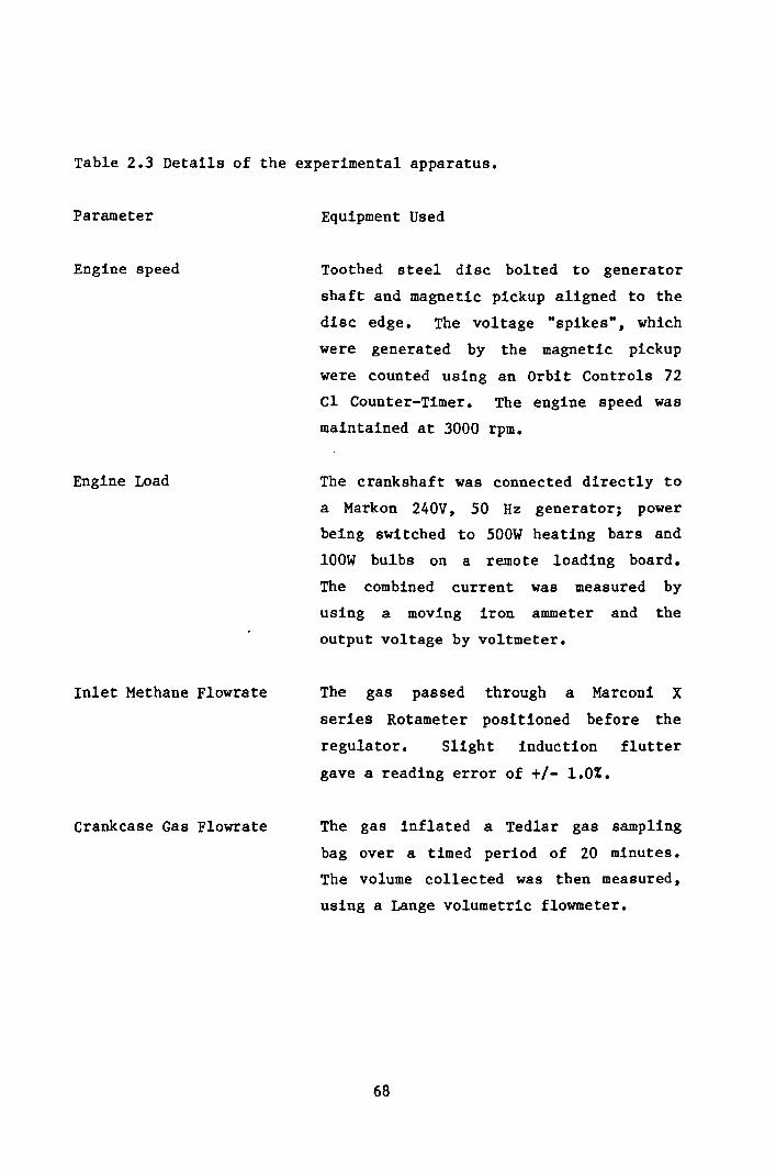
Table 2.3 Details of the experimental apparatus.
Parameter Equipment Used
Engine speed Toothed steel disc bolted to generatorshaft and magnetic pickup aligned to thedisc edge. The voltage "spikes", whichwere generated by the magnetic pickupwere counted using an Orbit Controls 72Cl Counter-Timer. The engine speed wasmaintained at 3000 rpm.
Engine Load The crankshaft was connected directly toa Markon 240V, 50 Hz generator; powerbeing switched to 500W heating bars and100W bulbs on a remote loading board.The combined current was measured byusing a moving iron ammeter and theoutput voltage by voltmeter.
Inlet Methane Flowrate The gas passed through a Marconi Xseries Rotameter posttioned before theregulator. Slight induction fluttergave a reading error of +/- 1.0%.
Crankcase Gas Flowrate The gas inflated a Tedlar gas samplingbag over a timed period of 20 minutes.The volume collected was then measured,using a Lange volumetric flowmeter.
68

Table 2.4 Thermal Conductivities at 45°c (Ref 2.22)
Helium 0.156Methane 0.037Oxygen 0.028Nitrogen 0.027Ethane 0.024Carbon Dioxide 0.018Hydrogen Sulphide 0.016 (J s-l m-I K-l)
Table 2.5 Calibration Gas Composition (Ref 2.23)
CH4 61.33 %CO2 28.63 %N2 8.04 %H2S 2.00 %
69

mm 1.0 30 4020
FIG 2.1 PHOTOGRAPH OF FORD DOVER CAMSHAFT BEARING CORROSION.
ORIGINAL BEARING SURFACE
0.1
0.2
0.3
mm
A B cFIG 2.2 CROSS SECTION OF THE BEARING SURFACE.
7.0
o

FIG 2.3 ELECTRON MICROGRAPH OF THE DAMAGED SURFACE.
FIG 2.4 ELECTRON MICROGRAPH OF THE DAMAGED SURFACE.
71

FIG 2.5 ELECTRON MICROGRAPH OF THE DAMAGED SURFACE.
FIG 2.6 ELECTRON MICROGRAPH OF THE DAMAGED SURFACE.
72

FIG 2.7 SECTION OF VILLIERS (-30 ENGINE
73

BRASS PLUG
FIG 2.8 SECTION SHOWING MODIFIED TAPPET HOUSING
74

-
3.5
803.0
78
76~ >-w::.:: z
UJ
'2.5 74 9u,._u,
::J UJa..I-
72~::J0
l-LL.-c
70::I:Vl::.::~2.00:w
1.5
T //
iii i i2.So 0.5 1.0 1.5 2.0
INDICA TED LOAD I KW
FIG 2.9 (ALIBRA TlON GRAPH FOR THE GENERA TOR
75

. dN ~~
yl.:J
0l- e
UJalt-
o: V')UJt-UJZL!JZL&J
UJ::ct-LL0
l:vi <
0::L!J«e0.-:N. L!JNL!-
a::L&.Jt- .UJ 0:: ....l: a.. 00 t-% c( t- V') t- e-c 0:: L&J t- Z a::l: t- o:: a:: :::l -cV')Ct: et: 0:::::::> 0 0:: 0
zLa.J L&.J La.J% oal a.. 0 L!J CD- l- t- 0::2 t-O:: t- z l!J<UJI.LJ :::::>Vl c(c( I.LJ I.LJ< x:l:l:l: Vl 0 ...JW ...J Z
a.. zO:: W« Vl...J :::::>V') L
_ I.LJt- eVlVlt- UJ a. l!J Z - c(
«<0 o::x ~« -c z L&J ~ 0l!Jl!J0:: a.. L&J a::L!J Vl La.Jl!l VI _,
rN(Tl~ O~NU1-Oc-....CX)O'~~~
76

.....VI:::J-c:r:xIoU
~ot--ca::l!JLLJt-~
.Ln
,_JL&J1l.a:J~o<0::Vt Q..
77
:l:LLJt-V)
>-V)
V)
V)
>-_.<I:Z<I:V)
-cl!J
L&J_.a.:l:<V)
LLJ:r:t-u,o1:<c:::l!J<{Cl
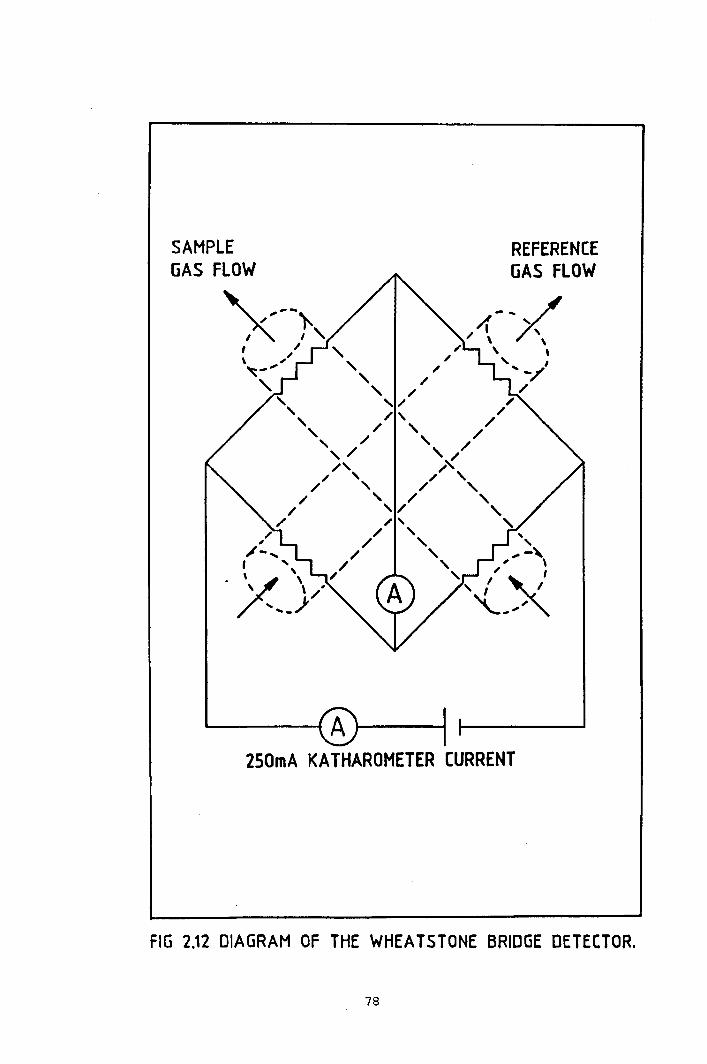
REFEREN(EGAS FLOW
2S0mA KATHAROMETER CURRENT
FIG 2.12 DIAGRAM OF THE WHEATSTONE BRIDGE DETECTOR.
78
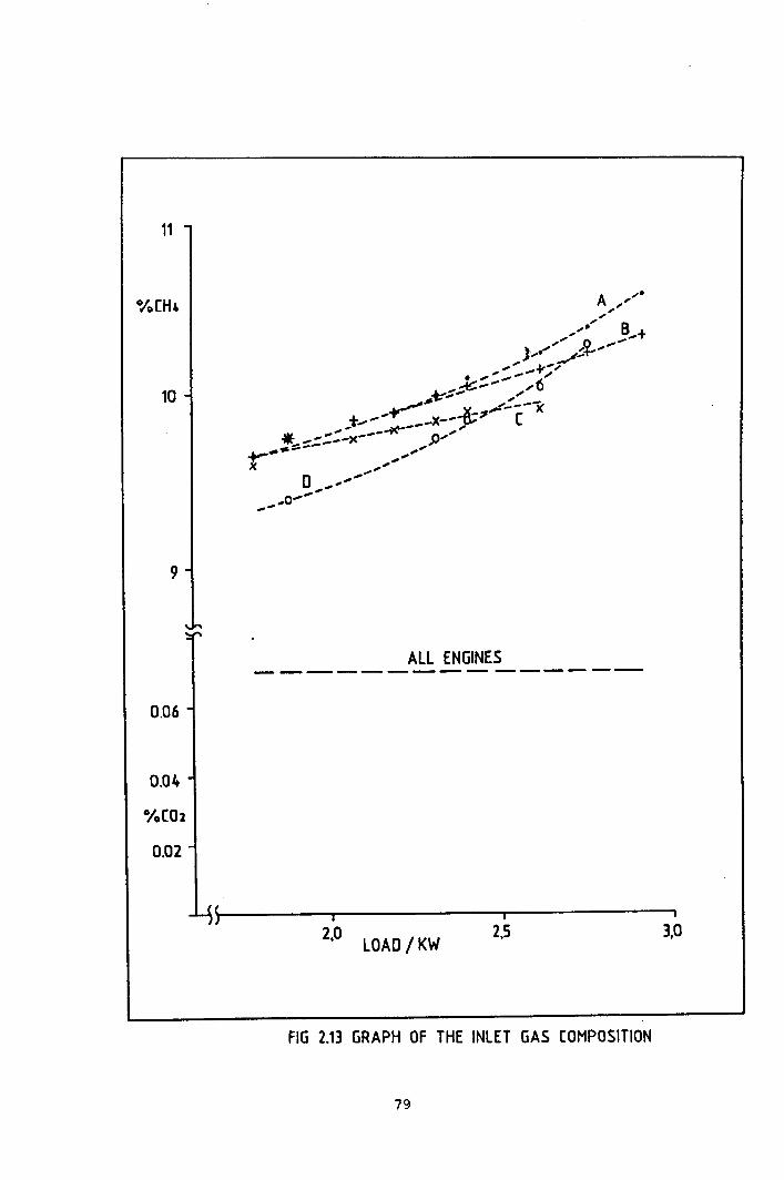
11
10
9
0.06
0.04
0.02
ALL ENGINES---------------
2,0 2.5 3,0LOAD /KW
FIG 2.13 GRAPH OF THE INLET GAS (OMPOSITION
79

0/0 (02
11
iOI
(/J( /0/ I" I
/ I/ fY /.
/ / ,/A/ / ;'I , /I I .,I / //
,I , "/ " // __ -...t, , / ..-v
I ,'/ ,..", I / ....+, a "" ..../1. ,,,,,
, 'J_f/, t,,," ,,:/'" ,,""I. ". /1
,.,....." II~"... ,(.1,; II
......., II
......." I I....", ,I~ I ,/
'Ko" I:t'If' /.v ' ,,/..." 1/, /,
/ ,X,/,?',',/'-= ALL ENGINESI ------------------------------,
-I
2,0 2,S
B
~~----~--------~------~
0.1
10
9
8
7
LOAD/KW 3,0
o
FIG 2.14 GRAPH OF THE EXHAUST GAS (OMPOSITION
80

7
.....'Vl
"., 61:U"l,0.....<,w 5t-etex:~0..Ju..
4
9
B
3
2
S +~+---++-----+--+--+--+----- j, • --- ---+.....- ---- ---.--_ .. --- ------'----.-------,,----y .'
A •
2,0 LOAD / KW 2,5 3,0
FIG 2.15 GRAPH OF THE BLOWSY FLOWRA TES
81

lLJV)
<\...J<,\...J
QJ:I:
~1.,0
7,0
6,0
5.0
ENGINE A
o
Ls't---' --r--~ __
2,0 2.5 3,0LOAD I kW
FIG 2.16 GRAPH OF BLOWBY METHANE CONTENT - ENGINE A
82

l1JVl«U<,l...I
zQ.I
1:
~L.O
'-7.0ENGINE B
6,0
5,0
2,0 2.5 3,0LOAD / kW
fiG 2.17 GRAPH OF. BLOWBY. METHANE CONTENT - ENGINE B
83
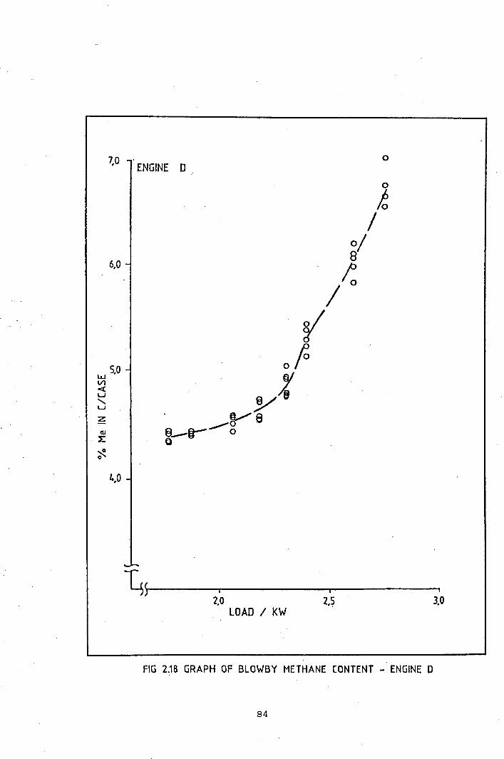
7,0 0ENGINE D
0
10/0/
6,0 8;:/r
5,0 0(0l1.J :tVl<u yS'"u~ '. yeC1l 9--0- _.,."01: Q
~0
1.,0
3,02,0LOAD / KW
2,5
FIG 2.18 GRAPH OF BLOWBY METHANE CONTENT - ENGINE 0
84

lI.JVI;:5 2,0<,w
Now
4,0ENGINE A
3,0
1,0
o
8 o
o oo
1,0 2,5 3,0LOAD / KW
FIG 2.19 GRAPH OF BLOWBY (01 (ONTENT - ENGINE A
85

u.IVI<u<,uZ
Nou
~1,0
4,0 ENGINE B
·3,0
2,0 o
o 8~__'o 0 ~__ 0
. _/"~~~ /LV"'" 0 -: 0 ~/o 0 ' 0
2,0 3,0LOAD / kw 2.5
FIG 2.20 GRAPH OF BLOWBY (01 (ONTENT - ENGINE B
86
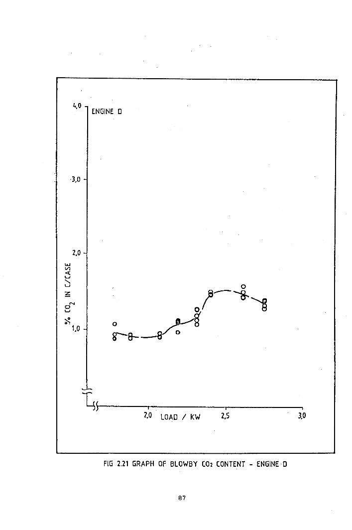
or-lU
~o.1,0
4,0ENGINE 0
2,0 LOAD / KW 2.5 3,0
·3,0
2,0
FIG 2.21 GRAPH OF BLOWBY (02 CONTENT - ENGINE· D
87

6,0,/0IIIII,IIII,
&,III; r(
//,'//1II/1I!/_,'
xl/,,6)(~,
/,0'»:........~..0.........;"
0"..... ;".,x/
x.......
~/./ ,l
_./+ ,/ A.+............ /_._....... "' ....
~T A-.--+~ ~-.-_+...- ..........J ...........t~"""""'- ......-_.-.,. - A-4~----~----------~--------~
5
4
2,0 LOAD / KW 2,5 3,0
FIG 2.22 GRAPH OF METHANE BlOWBY FlOWRATE
88

-IVl
",
1: 1..a'0-<,):o...Ju..
>-aJ):o...Ja:l
No'U
2
2,0 LOAD I KW 3,0
FIG 2.23 GRAPH OF (02 BLOWBY FLOWRATE
89
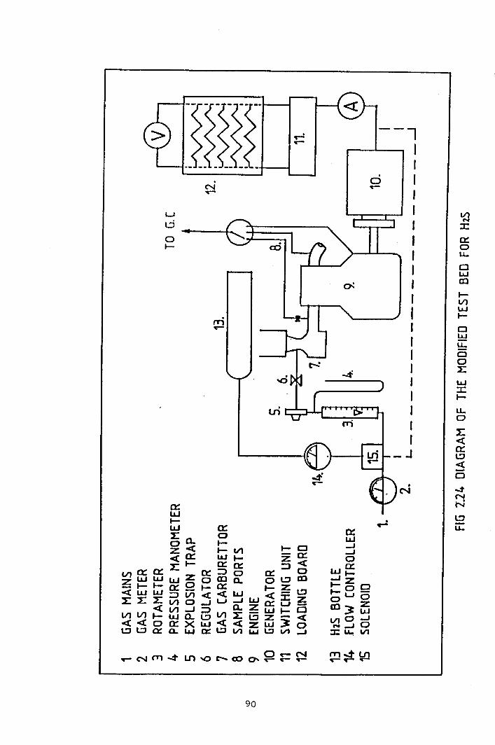
d
--lIIIIIr
•....
~:::cc:::ou..ClLLJal
l-V}LLJt-Cl~~CloLLLJ:::cI-u,o1:<{c:::l:J<{
Cl
..:tNN
LJt,:j
ot-
90

6 - ENGINE (
5
0.2
oI,
I,III,
,d,,JI
0'0,',
,'0,,,,,0,',
O,.(),-
"'00" ...--1'0----
METHANE
It .........)t)C )C--)C x __..~___ JC---
X )(
2,0 LOAD / KW 2.5 3,0
fiG 2.25 GRAPH OF THE BlOWBY GAS FUEL CONTENT
91
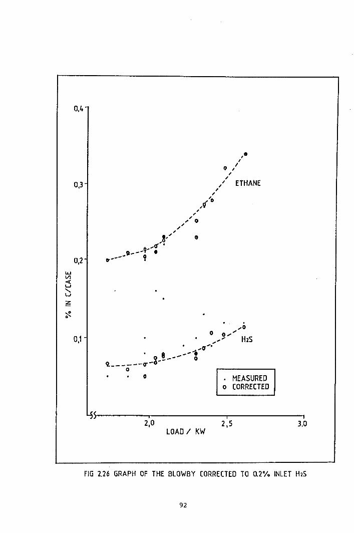
02'•lLJV1-cu<,u
t;
~0
0.1
0.4
0,3
,eI
I) ",," ETHANE,,
'0,9
. ,.....0
o 0 ..............,..... H2S. ,.,""
A'V
• 8 ......•-8----- 0Q. __ - - --ero
o MEASUREDo (ORRECTED
LOAD I KW2.5
I
3,0
fiG 2.26 GRAPH OF THE BLOWBY CORRECTED TO 0.2% INLET H2S
92

._:z~ 0,8:zoL.J_,lLJ::>u..._1.1.1_.:z'- 0,6
u,oo
~OJ40::
o
,a ",,,
,/.,' H2S,,
,. x'. """, le
".M ",',........ ; ."...... --___ ...-"'x
METHANE
•,.
2,5 3,0
FIG 2.27 GRAPH OF THE INLET TO BlOWBY (ON TENT RATIO
93

ENGINE 0TOC 1---------- ----------------~----- -,
. ~.-----_/'
./-://iIi
)//
60- /
BOC L -- ---- -------------------
10
20-
z~4O-Vioa..z~50Vl0::
i«(~~----~----~----~----~----~7, 20 I 30 I 40
TOP RING (jAP / THOU.
FIG 2.28 GRAPH OF THE PISTON RING GAP FOR ENGINE 0
94

400
I T I
LOAD / GRAMS~
1000I saoo
FIG 2.29 GRAPH OF THE CHANGE IN PISTON RING GAP WITH LOAD
95

et::«~0.4UJet::=>VlVlUJet::a.<,
"j1110.2,..E
'"Io.-
-0.4et::«~Wet::=>VlVlUJet::a.
'0.2..,:E
~
o
o
,0'"",'"
'"0' D""",
",'o -O--~'
..... ......_"...+ If-.....---t-=---:J.---. -_____ A+ -:t------+-----+B
2.0 LOAD / KW 3.02.5
FIG 2.30 GRAPH OF FLOW TO PEAK PRESSURE RATIO
t~-±----- ~-+-----+.--.__.~+~~____ B:r=
2.0 LOAD / KW 2.5 la
FIG 2.31 GRAPH OF % ME TO PEAK PRESSURE RA TID
96

--IIII
M:II:
'ro 2.0..--3o...JU.
4.0
3.0
1.0
o
,.I
A /III
,/"",--,........ ; /---------_._---.------------. .>;
. -+-----=+'+_~-+-r-+
oo---o-------o----o----o---Q..------o-----o
2.0 2.S 10LOAD / KW
FIG 2.32 GRAPH OF THE METHANE CONTENT TO FLOW RATIO.
97

Chapter 3. An investigation of the mechanism of blowby.
3.1 Introduction.
The experimental work has shown the quantity and composition of thegases in the crankcase. These could have entered the crankcase bythe following mechanisms:
(a) Passage of unburnt and then burnt gas past the piston rings.
(b) Ingress of fuel polluted air through the breather system.
(c) Transport by adsorption and then desorbtion from thelubricating oil.
(d) Retention of the trace gases in the crankcase for a longerperiod of time than predicted by the bulk flow of gases.
The work detailed in this chapter investigates whether the mostlikely route (a) can account for the gases in the crankcase. Thishas been done by an experiment to measure the the amount of gaspassing the piston rings for all engine combinations. A series ofcalculations are used to investigate the blowby flow and compositionand are based on the following rationale:
(a) Divide the combustion cycle into discrete increments and, usinga calculated position of the flame front, obtain the values offlow and composition for each increment.
(b) Sum the incremental values to obtain the blowby flow andcomposition across the whole combustion cycle, and analyse thetrends in flow and composition with engine load and wear.
(c) Analyse the data from both (a) and (b) above to evaluate themechanism of blowby, and compare the conclusions with thosederived from the experimental work.
98

In order to construct this analysis, the mechanism of b10wby in theengine is simplified, and account must be taken to consider all ofthe implications of any assumptions made. For the study of b10wby,the engine assembly can be considered as a system with twochambers. The combustion chamber is the source of the b10wby gases,which pass the piston rings and into the second chamber - thecrankcase. The b10wby is a function of the interrelationshipbetween cylinder pressure, piston position, and the progression ofthe combustion process during the combustion cycle. It is importantto consider the variables that will affect the piston bl.owby in arunning engine. Once identified, the calculations can be adapted toremove or simplify the variables. These can be identified as:
(a) Engine design. The b10wby mechanism is likely to be dependenton the dynamic interaction of the cylinder components, whichare different for each engine design.
(b) Operating parameters. The results of the previous chapter showthat both the bl.owby flow and composition vary with engineload. The increase in peak cylinder pressure with increasingload is a major factor of this behaviour. The way in which theengine is used will also affect the contribution from (c) and(d) below.
(c) Lubrication. A combination of engine operating conditions anddesign parameters will determine the lubrication within thering pack. The direct effect of the oil layer on blowby isunknown, but it will indirectly affect it through liner wear,ring sticking and piston deposits.
(d) Engine wear. As the engine ages, the cylinder liner becomesworn, and the piston rings lose their ability to follow thedeteriorating liner profile as a result of their permenentdeformation. The seal offered by the ring pack becomes lesseffective. This results in an increase in b10wby f10wrate.
99

The extent to which these variables can be controlled or eliminateddetermines the scope and limitations of the calculations. Theeffect of engine design on blowby formation was too complex asubject for this project, and a set of standard design parametersare difficult to relate to the experimental results obtained fromthe Villiers engines. In order to provide simple and readilyprocessed input data to compare with the experimental results, thecomplexities associated with the specific design of the Villiersengine must be eliminated. Compatible with the two chamber conceptintroduced earlier, the engine design and wear variables wereeliminated by using the engine itself as a source of input data.This was achieved by the use of the Static Piston experiment(Section 3.2). Piston blowby occurs when the pressure drop acrossthe piston ring pack is sufficient to overcome the sealing mechanismof the piston rings. The Static Piston experiment is a technique ofmeasuring the relationship between the cylinder pressure and blowbywithin a given engine assembly, allowing the direct comparison ofcomputed and experimental results. Lubrication was an unknownfactor, but was investigated in both Section 3.2 and in Chapter 4.Finally, the operating conditions, of which load is introducedindirectly through the pressure-crank angle diagrams (Section 3.3).Cylinder pressure is an input in the Static Piston Experiment, andalso in the flow simulation. Hence, the operation of an internalcombustion engine has been broken down into its basic operationalunit - the combustion cycle. Data obtained from the engine assemblyis used as the basis of the calculations, thereby eliminating thedesign related variables.
The calculations of the movement of gases between the upper(combustion) chamber and the lower (crankcase) chamber have been
oachieved by divided up the engine cycle into discrete 2increments of crank angle. The sectioning of the cycle enables anincremental blowby to be calculated for a series of piston positionsthroughout the combustion process. The use of data from thepressure-crank angle diagrams and the Static Piston experiment
o(Section 3.2) yields a pressure-flow relationship for each 2
100
incremental piston position. The programme uses the experimentalopressure for each 2 increment to generate an incremental flow.
After summation throughout the engine cycle, the calculated overallb10wby flow is obtained, and this approach is further developed toobtain a result for the crankcase gas composition. This is achievedby calculating the passage of the flame front across the pistoncrown, and obtaining incremental hl.ovby compositions. These aresummed across the engine cycle to derive overall composition.
3.2 The Static Piston Experiment
3.2.1 Experimental
The calculations described in this chapter are based on thepressure, crank-angle and flow measurements obtained by thisexperiment. The objective was to examine the variation of b10wbyf10wrate with both piston position and pressure, in a way in whichthe complexities of the combustion process (temperature, motion,change in composition) were neglected.
The flow measurements were taken from a series of tests on eachpiston/barrel combination. In each experiment, the piston positionwas fixed, a pressure applied in the cylinder head and the resultinghl.owby flow was recorded (Fig 3.1, Table 3.1). The bore profilesfor these engines have been measured, by the scratch technique (Ref3.1) and direct surface analysis by Ta1ysurf. The cylinder wearvaries with the past history of each engine, but all showed thegreatest wear near to the TOe position of the top ring. A decreasein flow was therefore expected by moving the piston away from Toe •
The crankshaft of the e-30 engine extends externally from the rearof the crankcase, and the generator shaft is joined to its end via a'doughnut' coupling system. The exposed end of the crankshaftprovided an ideal location for a clamping bracket. This enabled thecrankshaft, con-rod and piston assembly to be positioned and fixedwith the minimum disturbance of the internal engine components. For
101

each engine, a series of experiments was carried out, starting withthe piston at the TDC position and then moving it down the cylinderwall. For each experiment, the crankshaft was clamped with thepiston at the predetermined position, and then the exact pistoncrown height was measured using a depth gauge (Fig 3.2). The gaugemeasured the depth from a specially machined flat plate which wasfirmly bolted to the top of the engine by the cylinder head bolts.The depth gauge probe was lowered through the pressure transducerorifice (which was directly above the piston) and a reading of theheight of the piston crown was taken. This measurement was used toderive the corresponding crank angle (Eqn 3.1). The pressuretransducer was then installed into the cylinder head, and compressedair from a gas bottle was admitted through the spark plug hole viapressure tubing and a custom thread adaptor. The cylinder headpressure was controlled by a high pressure gas bottle diaphragmvalve, but the pressure readings used in the calculations were thosemeasured from the transducer installed in the cylinder head. Theresulting blowby was measured using a rotameter connected to thecrankcase breather. The pressure was gradually increased and thechange in blowby flow with applied pressure was recorded. Thepressure was taken above the maximum value recorded during enginerunning (Fig 3.6),' and then reduced back down to atmosphericconditions. The pressure transducer was then removed, and thepiston crown height was checked before the crankshaft was unc1ampedto set a new piston position. This procedure was repeated for arange of piston positions for engines A, Band D.
3.2.2 Results and Calculations.
The experiment was easy to perform, with the maximum appliedpressure being limited by the ability of the clamp to hold thecrankshaft in its original position. The measured f10wrates foreach piston position showed some disparity (maximum 5%) between thepressure rise and the pressure fall section of each test. Thevalues used in the calculations were the average of the two valuesat each pressure.
102
The b10wby flow readings were taken for a range of pressures up toand beyond those experienced by the engine under runningconditions. The results are summarised in Table 3.2. The depthgauge readings of the piston crown were corrected by the subtractionof the reading taken when the piston was at TDC (Le, the maximumheight recorded). This correction gave values of the pistonposition relative to that at TDC, which are related to the crankangle (8) by equation 3.1.
222cos 8 - x + s - 1 /2sx (3.1)
where 1· Con-rod length (127.5 mm)s - Stroke/2 (33.35 mm)x - (1 + s) - (height measurement/mm)
There are several experimental details that require discussion.This experiment was conceived as a simple means of imitating thedynamic b10wby flow through the piston ring pack. As such there areseveral differences between this experiment and the conditionsexperienced by the engine whilst running.
During the initiai development of the clamped piston b10wbymeasurement technique, an attempt was made to introduce an oil filmonto the cylinder wall, in order to simulate the oil film present inthe ring pack during actual running conditions. This involvedspreading a small amount of oil onto the cylinder wall and manuallymotoring the engine (with the cylinder head removed) until the oilhad spread evenly and also until no excess was pushed above the topring at TDC. The engine was then reassembled, and the crankshaftclamped. The Static Piston experiment was then carried out, and itwas found on comparison that the oil film made no difference to thebl.owby flowrate. This experimental observation is consistent withreports from several workers (Refs 3.2, 3.3, 3.4) that piston b10wbynormally occurs through the piston ring gaps, and under the staticpiston conditions, any oil in the piston ring gaps is likely to beremoved by the blowby gases flowing into the crankcase.
103

The experimental results shown in Table 3.2 were obtained withoutany attempt to create an artificial oil layer on the cylinderliner. This can be justified because:
(a) The lack of oil does not alter the static flowrate.
(b) The film consistency would be difficult to quantify betweentests, and any oil in the ring gaps would be forced out of theway by the moving gases.
(c) Oil in the top ring zone is highly degraded and is difficult toreproduce (see Chapter 4).
The wear at BDC occurs under similar conditions to that at TDC,because the piston experiences the same change in velocity, similarbreakdown in controlled lubrication and breakdown in piston ring asthat which occurs at TDC. The amount of wear is not as much as thatat TDC, however, because the cylinder pressure and temperature aremuch reduced at BDC, and the liner is extensively lubricated bysplash from the sump. No measurements were taken at BDC, because,pressurisation of the combustion chamber was not possible, as thevalves were open at BDC, and no simple method of overriding thevalve mechanism could be devised (Figs 2.7 and 2.8) • This isunlikely to affect the computer program because:
(a) The b.l.ovbyflow decreases as the cylinder pressure decreases.This occurs as the piston moves towards BDC on the power stroke.
(b) The hl.owby flow is likely to be very small after the exhaustvalve has opened on the power stroke, because the combustiongases would leave through the exhaust port in preference to themore restrictive route through the piston ring pack.
It should also be noted that these measurements were taken with acold engine, where none of the engine components had expanded totheir normal operating temperatures. Any attempt to heat the engine
104

was considered impractical, firstly because of the technicaldifficulty of sustaining the temperatures required, and secondlybecause it would be unlikely to re-create the temperaturedistribution that the cylinder components experience (the heat flow,from the heater into the engine block, would be in the reversedirection to that occurring whilst the engine is running).
Likewise, the piston was stationary and it was assumed that thepiston rings were forced hard against the cylinder wall by theapplied pressure from the combustion chamber. This assumption isvindicated by the consistency of the results with no outlyingreadings occurring as the result of incomplete piston ring sealing.In order to ensure consistent location of the rings, the piston wasalways positioned by upward movement prior to position measurement.This procedure was intended to locate the piston rings on the baseof the ring grooves. The quality of piston ring seal obtained isone of the major advantages of this technique, as the measuredf10wrates should be derived only from b.Lovby through the ring gapswith no contribution from ring flutter and independent of theability of the rings to follow the cylinder wall whilst in motion.
The gas used was compressed air at ambient temperatures. It has acompos! tion which approaches that of the inlet gases, but has adensity and viscosity which is different to the hot combustion gases.
3.2.3 Curve fitting of Static B10wby Data.
The results obtained from the Static Piston experiment representonly part of the possible combinations of pressure, crank-angle andb10wby f10wrate that could be obtained by this technique. A simplecurve fit routine has been employed to aid data handling. Themeasurements are co-ordinate points on a 3-dimensiona1 surface, eachengine having its own surface. These surfaces can be mathematicallydescribed by their appropriate equations. The curve fit techniquecan thus be used to generate a simplified source of data for use inthe calculations (an equation as opposed to a data matrix).
105

The equations were derived from the experimental measurements bycurve-fitting the data obtained from each engine. The results inTable 3.2 were curve fitted using a short program on the PETmicrocomputer. The program used an equation of the type:
F - P (a + bP) EXP (- cA) (3.2)
where F - f10wrate (10-4 m3s-1)P - pressure (Absolute Bar)A - ABS [0 - 360] (degrees)
(a,b,c) are the function coefficients derived from the data supplied.
This equation was used only because it approximated to the expectedshape of the 3-Dimensiona1 surface obtained by plotting crank angleand applied pressure against b10wby f10wrate. The programme uses Aas a function of crank angle 0, recognising that the position of thepiston is symmetrical about TDC (TDe - 3600 in the combustioncycle). The curve fit uses a quadrilateral function of pressure,where the constant in the quadrilateral equals zero because there isno flow at zero pressure. This is multiplied against a negativeexponential of the angle derivative, A, reflecting the anticipatedreduction in flow away from TDC. A manual check was made of theaccuracy of the curve fit routine, using the measurements from eachengine. The resulting surfaces are shown in Fig 3.3. The curve fitprogram explanation and listing appears in Appendix 1.
The resulting equations provide a mathematical relationship betweenpiston position, pressure and static piston flows for each engine.The range of the static piston pressure measurements, and thereforethe extrapolated limits of the derived equations, are beyond thosemeasured on the running engines. Hence, each engine has oneequation for the pressure-crank angle data obtained in section 3.3to calculate the incremental b10wby curves for all operatingconditions.
106

3.3 Measurement of Pressure-Crank angle diagrams.
3.3.1 Experimental
The next stage of data aquisition was to obtain the input pressureand crank angle information, from which a calculated blowby could bederived. The measurement of pressure-crank angle diagrams is a wellestablished technique (Ref 3.5).
The cylinder head pressure was measured as before (section 3.2),with the pressure transducer positioned directly above the piston.A timing plate was clamped to the crankshaft. This circular steeldisc had five notches machined into the outer rim at 100intervals, which, when picked up by a magnetic probe aligned near tothe rim, were used to indicate the exact piston position. Theposition of the notches in the timing plate were calibrated againstthe peak pressure recorded as the engine was motored, assuming thatthis pressure corresponded to TDC. The timing plate could be usedto measure both the position of TDC, and also to calibrate the crankangle scale on the X axis of the oscilloscope. The magnetic probeand pressure transducer signals were fed into the two channels ofthe Gould storage' oscilloscope, and the screen display wasautomatically recorded by the Gould plotter. The oscilloscopeproduced data which directly related crank angle to cylinderpressure, with the two traces superimposed to allow easy annotation(Fig 3.4, 3.5). These diagrams were produced for engines A, Band Dat a wide range of loads (Figs 3.6, 3.7, 3.8).
3.3.2 Calculations
Although the transducer calibration curve gives the linear variationin output voltage with pressure, the pressure-crank angle diagramshave no indication of absolute pressure. This is because thestorage oscilloscope displayed the pressure-crank angle output fromthe transducer, but the position of the Y axis gain had to beadjusted to display the curves, with no measurement of the offset
107

voltage. It is therefore necessary to adopt a base pressure. It
was assumed that the pressure of the system is atmospheric at Inlet
Valve Closure (IVC) and the calibrated readings were based on this
point. This assumption can be justified by two main factors:
(a) The calculated value for IVC is 227 °c (see below) which isoonly 47 C beyond BDC. The piston has just passed through
BDCwhere its vertical movement is relatively little (IVC -
8.35 mmabove the BDCposition), allowing the pressure in the
combustion chamber to stabilise.
(b) IVC is the point at which the combustion chamber becomes an
isolated system.
The exact angle of IVC was unobtainable from the manufacturers and
it was necessary to measure the angle on the test engine. The
inlet valve tappet clearance of engine B was set at the recommended
0.006 inch (cold) and, with the cylinder head removed, a dial gauge
was positioned to touch the centre of the inlet valve. The engine
was positioned beyond IVC on the compression stroke and the
crankshaft was rotated backwards until the dial moved, indicating
that the valve was moving. The exact position of IVC was determined
to better than 0.001 inch of valve lift. The height of the piston
crown was measured at this point by using a second depth gauge
inserted into the pressure transducer orifice (see Section 3.2.1).
This was repeated several times to establish the piston position at
IVC. The height of the piston at TDCwas also measured, and these
values were used in Eqn 3.1 to determine the crank angle at IVC.
The position of IVC was marked onto all the pressure-crank angle
diagrams obtained from the storage oscilloscope, and the pressure at
this point was assumed to be atmospheric. The transducer
calibration curve was used to obtain the pressures at all othero
points on the graph, and pressure data was taken for points at 2o 0intervals between 300 and 442 of crank angle. This data was
stored on computer disk for subsequent use in the b10wby calculation.
108

It should be noted that great care was taken to ensure that thepressure traces recorded were representative samples. Theoscilloscope had a storage facility allowing user comparison. ofcurves from individual firing strokes of the single cylinder enginewhilst it was running. There was some variation in the peakpressure values observed between cycles, especially at very low orhigh loads.
3.4 Calculation of Blowby Flowrate and Composition.
3.4.1 Flowrate Calculation
The Blowby flowrate has been calculated using the variants ofequation 3.2 for each engine, obtained from the curve fits from theStatic Piston experiment and input data from the pressure-crankangle diagrams. The 3-dimensional surfaces from Section 3.3 (Fig
o3.3) have been used to give flow increments for every 2 of crankangle of the combustion cycle. The purpose of obtaining a blowbysimuation in incremental form is that it allows analysis of theblowby process both during the combustion cycle itself, and also insummarized form to compare with measured flowrates.
The program listing appears in Appendix 1. It is presented togetherwith a line-by-line description of the program flow. The sameprogram calculates both the blowby flow and the blowby composition,using common input data and calculation subroutines. A glossary ofsymbols is also included.
Equation 3.2 can be used to generate blowby flow increments for anycombination of combustion cylinder pressure, and crank angle. Usingthe form of the equation specific to each engine (with variablesfrom Table 3.3), each 20 incremental point from a pressure-crankangle diagram can be used to generate the corresponding incrementalflow as a solution of equation 3.2. By solving the equation for allpoints on the pressure-crank angle diagram, the blowby flowincrements for the power stroke are generated. This is equivalent
109

to tracing across the surface of Fig 3.3. The values of b.Lowbyflow, pressure and crank angle are stored in arrays, to be displayedusing the PD4 plotter (see Appendix 1). In order to analyse theb10wby flow change during the combustion cycle, the flow is plottedagainst crank angle. Typical b10wby increment curves, derived fromthis technique, are shown in Figs 3.9, 3.10, and 3.11. As expected,these curves show a rapid increase in b10wby f10wrate as the pistonapproaches the TDC position, corresponding with high cylinderpressures and high bore wear.
An overall f10wrate is derived by the summation of the increments,subsequently divided by the cycle time (Eqn 3.3). Such a summation
oassumes that the b10wby occurring outside the region 300 too442 on the compression stroke is negligible. Fig 3.12 shows the
variation in computed crankcase fLowrat e with load for the threeengines, and compares them with the experimental f10wrates measuredin the work in Chapter 2 (Fig 2.15).
3 -1 ~B10wby flow (m s ) - [~(f1ow increments)] x [N/120] (3.3)
Several observations can be drawn from these derived f1owrates. TheStatic Piston experiment, from which these f10wrates wereoriginated, can be considered to be a measure of piston ring b10wbythrough the piston ring gaps. As such, it is only a component ofthe dynamic b10wby mechanism. The magnitude of the calculatedf10wrates obtained are close to those measured. For engine B (thelow wear engine), the agreement is very good, both the trend andmagnitude of the computed curve (within 10-5 m3s-1) confirmthat the b10wby mechanism for this engine is through the piston ringgaps only. For engines A (new) the values are three times, and for D(worn) the values are approximately twice those measured. Engine Ahas a similar curve shape for the computed and measured b10wby flow,whereas engine D has a computed curve that does not reflect thelarge increase in measured f10wrate observed at higher loads (Fig3.12). The result for engine A also shows that the mechanism ofb10wby is through the ring gaps only. The result for Engine D shows
110

that there are two mechanisms, ring gap blowby at low loads, and anadditional mechanism at high loads.
The curves show that the Static Piston experiment is a reasonableapproximation of blowby flow when compared with a running engine.The difference can be examined in terms of the limitations of boththe experiment and the calculation. Physically, the differencebetween the Static Piston experiment and the running engine has beensummarised in Section 3.2.2. For any given increment in the cycle,the effect of engine motion has been minimised by the division ofthe combustion process into such small components. However, theeffect of lubrication on the attitude of the piston ring throughoutthe cycle may be important. Any such effect must be slight, becausethe order of magnitude of the blowby flow has been calculated forall of the engines.
The important feature of the blowby flow results is the shape of thecurves in Fig 3.12, and their analysis during the combustion cycleitself in Fig 3.9, 3.10 and 3.11. The computed crankcase f10wratesshow a gentle increase with increasing load. This corresponds tothe difference in areas between the blowby increment curves, whichin turn are due to the differences in cylinder pressures experiencedat these loads (Figs 3.6, 3.7, 3.8). As Figs 3.9, 3.10 and 3.11show, the areas under the increment curves only divergesignificantly near to TDe, and it is at this point in the combustioncycle that any difference in blowby flowrate is determined. Forengines A and B, the shape of the calculated curve closely resemblesthat of the measured curve. This suggests that for an unwornengine, the mechanism of blowby is only through the piston ring gap,throughout the load range. However, for engine D, Fig 3.12 clearlyshows that, with increasing load and cylinder pressure, the blowbythrough the ring gaps, as represented by the calculated results,increases slightly, whilst in practice the measured flowrateincreases substantially. This feature can be explained in two ways.There are only five blowby increment curves for engine D, which givecalculated blowby results with more apparent scatter than those for
111

engines A and B. The derived points could be insufficient toprovide a clear picture of the overall curve. However, as alreadyindicated, mathematically, the difference between the calculatedflowrates for any given engine, is proportional to the difference inthe area under the pressure-crank angle curves obtained from that /engine at around TDC. The divergence required to provide themeasured curve shape has not been seen in practice. Therefore, itis unlikely that a pure combustion pressure effect, as calculatedfrom the Static Piston data, can explain the high flowrate at thehigh loads on engine D. This indicates that an additional mechanism(piston ring seal breakdown) is supplementing the ring gap blowby athigher loads. In comparing the curves from the different engines,it is clear that the supplementary mechanism occurs under differentloads for differing states of engine wear. For the newer engines,the measured blowby curves are similar to the computed curves. Forengine D there is some similarity at lower load with a transitionpoint followed by deviation of the measured curve from the computedcurve shape as the load increases.
It is important to note that both the experimental results fromChapter 2 and the calculation of blowby flow indicate that there ismore than one mechanism of blowby occurring in the engines at higherloads. In the calculation of b10wby composition, such a complexitymust be taken into account.
3.4.2 Calculation of B10wby Composition
In order to extend the calculations to derive blowby composition,several assumptions have to be made. The crankcase gas is formedfrom both burnt and unburnt fuel mixture as discussed in Section2.5. The composition of the blowby entering the crankcase duringthe combustion cycle, is obtained by dividing the combustion chamberinto two sections based on the position of the flame front, withunburnt charge in front of the flame, and combustion products behindthe flame. In this approach, the flame front is considered to be atransitional item with finite width, which moves rapidly across the
112

combustion chamber. As the Villiers engine is a side valve designwith an offset spark plug situated in the cylinder head directlyabove the two valves, the flame front will approach the cylinderbore and travel across the piston crown from one side. The programcan be greatly simplified by using a cylindrical combustion chamberwith the "ignition point" (I) at the top of the cylinder wall. Thecalculation of the combustion process is thereby confined to acylindrical chamber. This simplification can be justified on thebasis that the important region in blowby gas formation is thepiston and top ring zone, and not the remote areas of the side valvehead.
The composition of each of the blowby increments is derived from anextension of the flowrate calculations in Section 3.4.1. The blowbyincrement curves (Figs 3.9, 3.10, 3.11) are divided into pre- andpost- combustion curves based on the relative position of the flamefront. This divides the piston crown, and the ring pack directlybelow it, into two sections, giving the two component compositionsto the overall blowby. The assumptions used here are that:
(a) The flame front passing across the piston crown is sphericalwith its centre at the ignition point (I), and travels withturbulent velocity which is assumed to be constant (thecorrection for the flame propagation prior to speedstabilisation is given in (b) below). The flame velocity wasmeasured experimentally.
(b) The flame propagation delay (pre-turbulent combustion) and timefor the flame to travel from the spark (real position) to pointI (imaginary position) are accounted for by a delay in thecombustion program ignition (See Fig 3.13).
(c) combustion is assumed to be completed within the flame frontwhich has a negligible depth. This assumption is made for theconvenience of calculating the exact division of the pistoncrown by the flame front. In practice, the resolution of the
113

flame position is compromised by the 20 of crank anglebetween each calculation.
(d) The inlet and exhaust gas compositions measured in themanifolds are taken to be equivalent to the gas mixture presentin the combustion chamber before and after the flame frontrespectively (See Figs 2.13, 2.14). These are referred to aspre- and post-combustion gases within the combustion chamber.
(e) There is no correction for a quench zone component, all gasespassing through the ring pack are derived from pre- orpost-combustion gases as defined in (d) above.
(f) The pressure either side of the flame front is equal, and thatboth pre- and post-combustion gases have the same ability topass the piston ring pack.
(g) The location of the top ring gap is not important in thedetermination of overall composition. Tests were conducted todiscover the mobility of the rings around their grooves, and itwas found that the orientation of the rings was completelyrandom after running. The composition results assume completemobility of the top ring, and hence there is no correction forring gap position.
The calculations advance the flame front position for each incrementduring the combustion cycle. It was therefore necessary to measurethe flame speed inside the combustion chamber. This was measuredusing ionization gaps installed into the cylinder head, the outputfrom which were fed into the Gould oscilloscope (Fig 3.14). Theflame front contains high temperature ions and free radicals, whichallow current to pass across the ionization gaps. The separation ofthe ionization peaks (as time on the oscilloscope's X axis) combinedwith the measured separation of the ionization probes gave the flame
-1speed of 36 ms over a range of loads up to 2 kW.
114

The mathematical basis is that of a simplified cylindrical
combustion chamber with an ignition source (I) at the top of the
cylinder liner sidewall (Fig 3.13). The flame front progress isocalculated for each 2 of crank angle, corresponding to the
pressure-crank angle diagrams and the blowby increment simulation.
The object in the calculation is to divide the blowby up into two
component parts from either side of the flame front, corresponding
to the amount of burnt and unburnt combustion mixture passing by the
ring pack. The program achieves this by:
(a) Testing to see if the flame front has reached the piston crown
directly below the ignition point (I) (Fig 3.13). If this has
not occurred then all the b10wbywill be unburnt gas.
The ignition point is a fixed distance from the real ignition source
- the spark plug , At an assumed constant flame speed, the flame
will reach the top of the cylinder at the same point in the
combustion cycle, independent of load. After this delay, flame
initiation occurs from point I, with the flame travelling radially
away from I into the cylinder bore. The increase in flame radius
per 20 increment is constant (Eqn 3.4) and the total flame radius
will be the sum of all increments (Eqn 3.5).
Flame radius from ignition point (I).
Radial increase per increment (FRi) - (36 x 60)/(3000 x 180) (3.4)
where Engine speed - 3000 rpm3 -1
Flame speed • 36 m s
(3.5)
As the flame front expands towards the piston crown, the piston
moves upwards, compressing the unburnt gas mixture. The position of
the piston for any crank angle can be calculated using equation 3.1(see Fig 3.2) as the solution to the quadratic (Eqn 3.7). This
115

piston crown position is relative to the crankshaft centreline, andcan be used to derive the distance between the piston crown and thetop of the cylinder bore (Eqn 3.8).
Piston crown position
For any crank angle 9, from the cosine rule
(From 3.1)
Rearranging (3.6)
Solving quadratic (3.7)
Dist to top of stroke - (L + s) - x
Dist to top of bore - (L + s) - x + j - IX
~ 2 2 2IX - L + s(l - cosO) - L + s (cos 9 - 1) + j (3.8)
where e - crank angles - stroke/2 .L - con rod lengthj - distance between TDC and top of bore (3 mm)
The flame front will reach the piston crown initially at the point(X) directly below the ignition point (I). Until IX - FR, all theblowby is assumed to be unburnt fuel mixture (see Fig 3.13).
(b) Calculating the flame front's progress across the piston crown,thereby dividing the piston circumference into two parts. Thiscorresponds to the fractions of burnt and unburnt gasescombining to form the blowby.
116

As the flame spreads across the piston crown, it engulfs an areawhich can be represented mathematically as part of the base of acone (Fig 3.13). At any stage in the combustion cycle, the engulfedvolume is considered to contain burnt gases and the remainder is, asyet unburnt. From simple geometry,
At any stage FR - lY - lA - lB (3.9)
Also XY -j (FR)2 - (IX)2 (3.10)
And XY - XA - XB (3.11)
Therefore sin ~ -~(FR)2 - (IX)22CB
(3.12)
Fraction engulfed - 4~/360 (3.13)
Fraction unburnt - (360 - 4~)/360 (3.14)
oFor each 2 increment, the piston circumference is divided up inthis manner until the flame front has engulfed the whole pistoncrown.
(c) Testing to see if the flame front has traversed the pistoncrown to the point directly opposite the point of initial flamecontact, after which, all the blowby is assumed to be burnt gas.
The piston crown is completely engulfed when the flame radius hasreached the point diagonally opposite to the ignition point (1).
This occurs when the base of the cone is equal to the pistondiameter.
Piston is engulfed when 2CX -vl(FR)2 - (lX)2 (3.15)
The resultant two fractions, obtained for each blowby increment fromthe f10wrate simulation in Section 3.4.1, are used to divide up the
117

blowby in that increment. The composition of the blowby for each
20 increment is determined by mUltiplying the corresponding
fraction with the composition of the pre- and post-combustion
gases. The composition of the crankcase gas is the sum of the
composition of all the increments. This calculation uses the
measured compositions of the inlet and exhaust gas samples from Figs
2.13 and 2.14 to represent the pre- and post-combustion elements of
the summation.
This approach allows an examination of both the composition of the
blowby across a typical combustion cycle (Fig 3.15, 3.16, 3.17) and
the summarized compositions (Fig 3.18). As expected, in the early
stages prior to and for some time after ignition, the blowby gas is
all unburnt fuel mixture, because the flame front has not reached
the piston crown. Within the region of the power stroke between
3400 and 4100 the flame front crosses the piston crown, and the
blowby gas is a combination of pre- and post-combustion mixture.
Beyond 4100 the blowby gas is all post-combustion mixture.
The computer program stores the fraction of burnt and unburnt gas
from each increment, and sums the fractions over the whole
combustion cycle. the product of this calculation is the overall
fraction of gas flowing through the ring pack from either side of
the flame front (equations 3.16, 3.17). The post-combustion
fraction CF(E) is then adjusted to remove the effect of the water
vapour, which is present in the ring pack as a gas, but which is
condensed from the crankcase gases prior to analysis. The
correction is derived from the stoichiometric combustion as given by
equation 2.9. The correction is given in equation 3.18, and then
the composition of the crankcase gas is derived from equation 3.19
by the summation of these increments. The inlet and exhaust gas
compositions used in this calculation are shown in Fig 2.13 and
2.14. The resulting blowby composition curve is shown in Fig 3.18.
118

(F(I» / (F(I) + F(E» • CF(I) (3.16)
(F(E» / (F(I) + F(E» - CF(E) (3.17)
CF(E) corrected = CF(E) * 0.810 (3.18)
CF(I) x Inlet comp + CF(E) x Exh comp - B10wby comp (3.19)
where F(I) - Pre combustion incremental fractionF(E) - Post combustion incremental fraction
CF(I) - Total cycle pre combustion fractionCF(E) - Total cycle post combustion fraction
Equation 3.19 can be applied to any gas present in both the inletand exhaust gas samples. The result of this calculation gives amethane content of the b10wby which is very close to that measuredat low load. However, as the load increases the measured methanecontent rises rapidly, but the calculated content varies little withload. This result parallels that of b.Lowby f1owrate, where themeasured results diverge from the calculated results. Thisdiscrepancy can be explained in a similar manner for bothparameters. In order for the calculations to generate a wide changein composition with load, the incremental fractions must besignificantly different. As Figs 3.15, 3.16, and 3.17 show, this isnot the case because the way in which the flame front crosses thepiston is similar for all loads and the b10wby flow increment curvesare similar for all loads.
3.5 Discussion of the computed results.
The measurement of b10wby f Lowra te in Chapter 2 identified threeproposed mechanisms of piston b1owby.
(a) B10wby through the piston ring gaps.
119
(b) Blowby around the piston rings as they move away from thesealing surface on the piston groove as the piston passesthrough TDC.
(c) Blowby between the piston ring outer face and the cylinder iliner as a result of the breakdown of the piston ring seal.
The possibility of any indirect technique of gas transport, such asthat of gases dissolved in the oil, will not significantlycontribute towards the quantity and composition of blowby measuredfor each engine.
The Static Piston experiment was devised to measure piston ring gapblowby, with the major assumptions that the applied pressure wassufficient to cause the piston ring to seal and that the propertiesof compressed air would parallel those of the blowby gases. As suchthis technique examined the mechanism which is considered in theliterature to be the major source of piston ring blowby.
The flow and composition results derived from the calculations yieldgood agreement in magnitude. However, the trend of both parametersacross the load range is not representative of the increase measuredin practice. In the analysis of this feature, it is important torecognise the limitations of the calculations in its initial form,and to evaluate the information gained from these results.
As discussed in section 3.4.1 the blowby flow calculations yieldedblowby flow results close to those measured, the approximation beingparticularly good for engine B. However, the change in flowratewith load for engine D is not calculated with confidence. Theproposed explanation for this discrepancy is based on the nature ofthe pressure dependence of the calculation. A comparison of thecomputed curve shapes in Fig 3.12, and the measured resultsdisplayed in Fig 2.30 show good agreement. Both indicate thatblowby flowrate is proportional to cylinder pressure, except forengine D at high loads.
120

The calculated f10wrate is derived from equation 3.2 (Fig 3.3).Throughout the combustion cycle, the increase in f10wrate with loadfor any given increment is dependent on the increase in pressurewith load. In summing the increments across the combustion cycle,the overall bLowby f10wrate is dependent on the area under thepressure-crank angle curves. As a comparison of the pressure curvesin Figs 3.6, 3.7 and 3.8, and the f10wrate curves in Figs 3.9, 3.10and 3.11 show, the difference in areas under all the curves, whichincrease wi th load, is not large enough to provide the measuredincrease in f10wrate. The conclusions that can be reached are:
(a) The mechanism of b10wby as measured by the Static Pistonexperiment (blovby through piston ring gaps) can be used toapproximate the dynamic f10wrate for all the engines, but onlyprovides the trend with load for low wear engines.
(b) The bl.ovby through the ring gaps for any engine varies withcylinder pressure across the load range.
(c) The b10wby in low wear engines occurs through the piston ringgaps, and not as a result of ring seal breakdown.
(d) There must be another mechanism of b10wby occurring at highwear and/ or high load. The proposed mechanism is piston ringseal breakdown.
The extension of the calculations to introduce piston ring sealbreakdown must involve a consideration of both the potentialmechanisms of piston ring seal failure, the mechanisms of gastransfer within the ring pack, and also the conclusions drawn fromthe initial derivation of b10wby composition.
In proposing a rationale for piston ring seal breakdown, it isimportant to understand the sealing mechanism. There are two maintypes of piston ring, compression and oil control. The Vi11iersengine has three identical compression rings and one oil control
121

ring. The top compression ring is the most important ring in thesealing of the ring pack because it is the ring directly in contactwith the pressure from the combustion chamber.
The piston ring is radially compressed to ensure that there isalways an outwards force by the piston ring onto the liner surface.The ring is held in a piston groove which is slightly oversized, butwhich prevents excessive twisting of the piston ring during verticalmotion of the piston and ring assembly. The ring experiences forcesin the direction of piston travel related to the movement of thepiston, and also due to the difference between the combustionchamber pressure and the pressure below the ring sealing face.
During the compression stroke, the piston is moving towards thecombustion chamber, compressing the inlet fuel mixture. The pistonring is firmly seated onto the base of the groove, and thecombination of the outward force from the ring itself, and the highpressure of the gases above and behind it, force the ring onto thecylinder wall (Fig 3.19). Friction and wear as a result of ring toliner contact is prevented because the ring running face islubricated and supported by hydrodynamic oil lubrication (seesection 4.1.2 and Fig 4.1). The combustion chamber pressure is themajor sealing force, because it is the pressure drop across thepiston ring that holds the ring onto the base of the groove. Inhigh speed engines, the cycle time is very short, allowing only asmall amount of blowby through the piston ring gaps per cycle. As aresult, there is a large pressure drop across the top ring, with arelatively small drop across the rest of the ring pack.
As the piston approaches and passes through TDC, the movement of thepiston slows rapidly, and reverses direction. The ring experiencesa decrease in upward force imparted by the base of the pistongroove, and an increase in friction with the cylinder liner as thelubrication begins to break down. These combine to upset the sealbetween the ring and the base of the groove. As the piston passesthrough TDC, the seal can be broken momentarily if the pressure from
122

the combustion chamber is insufficient to hold the ring onto the
groove base. This breakdown normally occurs only on the exhaust
stroke, where the combustion chamber pressure is low. On the
compression and power strokes, the combustion chamber pressure is
high and ring flutter is less likely. Beyond TDC on the power
stroke, any ring flutter will cease as the seal is rapidly
reinstated by the combustion chamber pressure.
This sealing mechanism is further complicated if lubrication is poor
(boundary conditions or worse), or if piston grooves or cylinder
liner is worn. These combine to reduce the effectiveness of the
seal at both the groove base and the liner wall. Under these
conditions, the pressure of the gases above the ring cannot maintain
the seal integrity, and b10wby occurs, particularly as the piston
approaches TDC.
From this analysis of piston ring seal breakdown, there are two
major failure modes:
(a) Ring flutter as the piston passes through TDC. This feature is
usually prevented from occurring during the power stroke by the
correct design of the engine. The duration of the loss of the
seal and the quantity of b10wby passing through the ring pack
is related to the combustion chamber pressure and engine wear.
This mechanism is only likely to contribute a small constant
amount of bl.ovby across the load range, because during the
exhaust stroke the combustion chamber pressure is low and the
frequency of the breakdown is dependent on the motion of the
piston.
(b) Ring seal breakdown as a result of component fatigue and wear.
This is likely to occur near to TDC at high pressures. This
mode includes ring flutter on the power stroke, induced by
excessive wear which becomes indistinguishable from general
seal breakdown. The b10wby is related to the combustion
chamber pressure and the condition of the components involved.
123

Fig 3.18 shows that the derived composition of the b10wby gas isrelatively constant across the load range for all of the engines.This result has been obtained by a straight forward division of theb10wby into pre- and post-combustion gases, and its derivation froma pressure-flow relationship. Several factors must be taken intoaccount when considering a more complex approach.
The region around the top ring is likely to contain quench gases,and as the flame front crosses the piston crown, it will be quenchedas it approaches the ring crevice. Therefore, no matter how theb10wby passes the ring pack, quench zone gas is likely to pass intothe crankcase followed by the gas from the bulk volume of thecombustion chamber.
The flame front passing across the piston crown has been simulatedas being of negligible width, spherical and travelling at constantvelocity corresponding to well established turbulent combustion. Noattempt has been made to include any effect of mixture turbulencenear the flame front.
There has been no attempt to investigate the complex nature of thecombustion process, or the mixture distribution within thecombustion chamber. The fuel is a gas at STP, and with noatomisation required, the mixture distribution should be very good.However, the calculation of b10wby composition is based on themeasurements of mixture content in the inlet and exhaust manifolds.The corresponding pre- and post-combustion gases within thecombustion chamber must be compared with the measured gases.
The major physical differences between the gases inside and outsidethe engine are those of temperature and pressure. Of these, onlythe combustion product, water, will be significantly affected. Inthe combustion chamber, the water is a gas, only condensing incooler parts of the exhaust system, or within the crankcase. Thewater passing through the piston rings is derived from the post-combustion gases. In the analysis of the inlet, exhaust, and
124

crankcase gases, water is eliminated (a dry analysis). Thecorrection of the calculated blowby to include the condensation ofthe water gives the composition of the calculated crankcase gas.This has been carried out to give the results shown in Fig 3.18. Afurther correction could be included to compensate for thedifference between the the viscosity and density of the ambient airused in the Static Piston experiment, and that of the combustiongases within the combustion chamber. This would require theinteractive feedback of the predicted composition of the blowbygases into the calculation routine.
The computer calculation is based on data obtained from the engineassembly. In comparing the computed and actual results, thefollowing conclusions can be drawn.
(a) Both results indicate that the blowby flowrate through thepiston rings is approximately constant across the load range.This b10wby mechanism occurs for newer engines, and wornengines at low loads.
(b) The blowby flowrate for worn engines at higher loads includesan additional mechanism not operating at low loads.
(c) The fuel content of blowby does not occur as a simple divisionof the combustion chamber gases by the flame front. At higherloads the fuel content rises, indicating that larger amounts ofunburnt mixture and quench zone gases are passing through thering pack early in the combustion cycle.
The calculations are limited by the Static Piston experiment, whichwas designed to imitate the blowby flow in a working engineassembly. This method has produced results which confirm thepostulated mechanism of blowby formation proposed in the discussionof the experimental data. An extension of the calculation routine,to include more detailed analysis of the behaviour of the gases atthe ring pack, is required to further evaluate the mechanism.
125

References Chapter 3.
3.1 RASSAAN, R.A "An investigation into the absolute life of anInternal Combustion Engine". PhD Thesis, Leicester Polytechnic, 1983.
3.2 PAYNE J Q, SIGWORTH R W "The composition and nature of b10wby andexhaust gases from passenger car engines." Proc 2nd Nat Air Poll Symp1952 Vol 2 pp 62 - 70.
3.3 BENNET P A et a1, "Reduction of air pollution by control ofemission from automotive crankcases." SAE Transactions, Vol 68, pp 514- 536.
3.4 Department of Industry Report TRD 162, Piston Ring Design 1974.
3.5 TAYLOR C.F "The Internal combustion engine in theory andpractice." 2nd Ed MIT Press 1983 pp 114 - 119.
126

Figures Chapter 3
Fig 3.1 Diagram of Static Piston Flow apparatus.Fig 3.2 Diagram of Piston position measurement.Fig 3.3 Static Piston flow surfaces.Fig 3.4 Diagram of Pressure-crank angle apparatus.Fig 3.5 Diagram of pressure-crank angle oscilloscope display.Fig 3.6 Diagram of pressure-crank angle curves for engine A.Fig 3.7 Diagram of pressure-crank angle curves for engine B.Fig 3.8 Diagram of pressure-crank angle curves for engine D.Fig 3.9 Blowby increment curves for engine A.Fig 3.10 Blowby increment curves for engine B.Fig 3.11 Blowby increment curves for engine D.Fig 3.12 Graph of computed and measured blowby flow.Fig 3.13 Diagram of mathematical basis of flame front calculation.Fig 3.14 Diagram of flame speed measurement apparatus.Fig 3.15 Blowby composition increment curves for engine A.Fig 3.16 Blowby composition increment curves for engine B.Fig 3.17 Blowby composition increment curves for engine D.Fig 3.18 Graph of computed and measured blowby composition.Fig 3.19 Diagram of compression ring sealing.
Tables Chapter 3
Table 3.1 Static Piston Experimental Apparatus.Table 3.2 Static Piston Experiment Results.Table 3.3 Static piston equation coefficients.
127

Table 3.1 Equipment used for Static Piston Experiment
Parameter Equipment Used
Applied Pressure Southern Instruments T 500 pressuretransducer with readout unit.Voltage display by Hewlett PackardD.V.M.
F10wrate Marconi X series and S 45 Rotameters.
Table 3.3 Static Piston Coefficients.
EngineA
B
D
a b
-0.00965-0.0065-0.00612
c
0.507970.350101.43155
0.000090.01510.02823
128

ENGINE A ENGINE B ENGINE 0ANGLE P FLOW ANGLE P FLOW ANGLE P FLOW360.0 6.16 2.56 360.0 4.85 1.74 360.0 7.17 7.768.68 3.40 6.71 2.06 10.74 13.1811.38 4.15 8.33 2.31 14.40 18.3914.02 4.80 10.07 2.63 18.09 23.1616.62 5.58 11.97 2.99 21.76 27.2919.22 6.14 13.76 3.27 25.46 30.97372.7 6.01 2.5 15.49 3.53 375.9 10.68 7.768.69 3.38 17.14 3.79 14.46 10.5811.29 4.11 20.66 4.34 18.06 12.9613.96 4.81 24.18 4.83 21.77 14.70
16.51 5.46 383.8 10.7 1.95 25.46 16.2219.10 6.11 12.62 2.11 386.2 10.35 5.59383.6 4.97 1.98 14.37 2.29 14.03 8.416.2 2.34 16.25 2.44 17.74 10.14B.7S 3.15 18.24 2.68 21.30 11.66
11.39 3.85 21.8 2.89 25.21 13.1814.05 4.~5 25.61 3.09 399.5 3.31 1.6116.55 5.20 397.9 12.24 1.85 4.85 2.0019.17 5.88 14.01 1.98 6.57 2.44391.5 4.64 1.95 15.83 2.13 8.28 3.026.16 2.31 17.58 2.26 9.78 3.46B.78 3.12 19.65 2.42 11.51 3.8511.32 3.B 408.9 13.44 1.B5 13.23 4.2613.97 4.47 404.4 4.9 2.0516.52 5.15 6.68 2.1619.09. s.B2 8.29 2.63397.8 4.93 1.95 10.05 3.156.23 2.39 11.71 3.518.75 3.17 13.35 3.90
11.31 3.Bs 409.8 4.76 2.1814.06 4.68 6.44 2.21409.0 4.93 2.08 8.21 2.786.14 2.37 9.95 3.227.41 2.B1 11.49 3.61B.7s 3.3 13.10 3.93
10.01 3.1211.31 4.00
438.6 4.92 2.03 Angle: Deg A.T.D.C6.14 2.42 Pressure: Absolute Bar7.39 2.B9 Flow: 10-4 m3 &-18.66 3.28
Table 3.2 Static Piston experimental results
129

·LI1
Vl:::::>t-etc:::eta.a.et~0_,u,
:z0t-Vla.ui=.et
IT\ t-Vl
UJ::J:t-u,0
l:etc:::l!JetCl~,...,t::Ju..l:
>Cl
t-Z:::::>
130

II X
1~
XI
~1 <, <,\ N_J
\ ._I
---of~- NV) ZJ LLJl:\ / + LLJ\ / et:I
NX ::J-,'i~./ V1
" -cLLJI CD l:
I
.1I/)
~
V)
0 z+u
52_,
t-V)0
•
a.z0._!:1a.u,0
l:«et:l:J«ClLLJ
~,...,....-c
l:J
....I
u,
131

ENGINE A
,0
ENGINE B
ENGINE D
FIG 3.3 STATIC PISTONFLOW SURFACES
132

....Z:::J
t-:::>a.....:::>a
133
Vl::>....<a:::<a.a.<L&J~L.:JZ<~z<a:::w
L&Ja::::::>VlVlUJ.~a.UJ::t:....u,ol:<c:::L.:J-cCl
04'.rrl
l!Ju..

>-<_,o,~Clwc,0\oJVl0_,...J
U ·0Cl Vlt- O
u..0
l:<0:l:J!5Cl
~,..;l:Ju..
u2:-
134

"15 0::<19w0::::J(J)U)W0::n,
0::w1121 0z~
_J>-U
5
IENGINE A I
36~ 42~CRANK ANGLE C DEG. A. T. D. C )
FIG 3.6 PRESSURE - CRANK ANGLE CURVES FOR ENGINE A
135

I ENGINE B I
3~ ......~<(9
w~:JU)U)w~0..
~W
2~ 0z......J>-u
1121
312m 36~ 42121CRANK ANCLE C DEC.A.T.D. C )
FIG 3.7 PRESSURE - CRANK ANGLE CURVES FOR ENGINE B
136

1.5 "~<[9
w~:JUlUlW~Q..,
~w
i a 0z.....
5
I ENGINE 0 I
36~ 42~CRi\NK i\NGLE ([lEG. 1\. "T. D. C J
FIG 3.8 PRESSURE - CRANK ANGLE CURVES FOR ENGINE 0
137

8
I ENGINE A I,.....-4I1I1
(YlLvIlSI
6r4
'""t-ZWz;W~UZ_,
~0.Ju...
4 >-m~0.Jm
2
36~ 42~CRANK ANGLE COEG. A. 1. D. C ')
fiG 3.9 BLOWBY INCREMENT CURVES FOR ENGINE A
138

4
IENGINE B I,.......IlJ1
(Yl:Eo<r;t"IfSI...
'3 ....I-Zw~wo;uz.....;:!I:0Ju,
2 >-ID;:!I:0_JID
1
3£1£1 36£l 42£lCRANK ANGLE <DEG. (\. 1. c. C ')
FIG 3.10 BlOWBY INCREMENT CURVES FOR ENGINE B
139
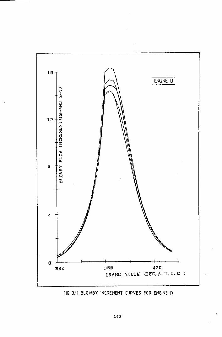
16
I ENGINE 0 I"....IlJ1
(11LVI~....
12 '"'t-ZWLW0:::uZ......~D..Ju..
8 >-III~0_JIII
4
36~ 42~CRANK i\NGLE CIJEG. t: 1. o. c )
FIG 3.11 BLOWBY INCREMENT CURVES FOR ENGINE 0
140

4 64- -+__ +- '1.
~- ---6~ ... ----_ ..------ ---- ---------------------- ----------. A~-----------------
j 10VI""1:'"'0or-
I.I.J
~ 80:~o...Ju,
>-aJ~ 6saJ
14
12
2
O'-----~O-:-
;'"..---_ ..-. ----'..---~-..---
- (OMPUTED------ MEASURED
2,0 LOAD/KW
o no
, D,.',
",",,
",,",,, ~-
o2,5 3,0
FIG 112 GRAPH OF COMPUTED AND MEASURED BlOWBY FLOW
141

SPHERICAL FLAME WITH RADIUS IV ENGULFS PISTON CROWN AS PARTAREA OF CONE BASE
ANGLE OF COVERAGE 416 IS CALCULATED FROM ENGULFMENT RADIUS
FIG 3.13 MATHEMA TICAL BASIS OF FLAME FRONT POSITION.
142
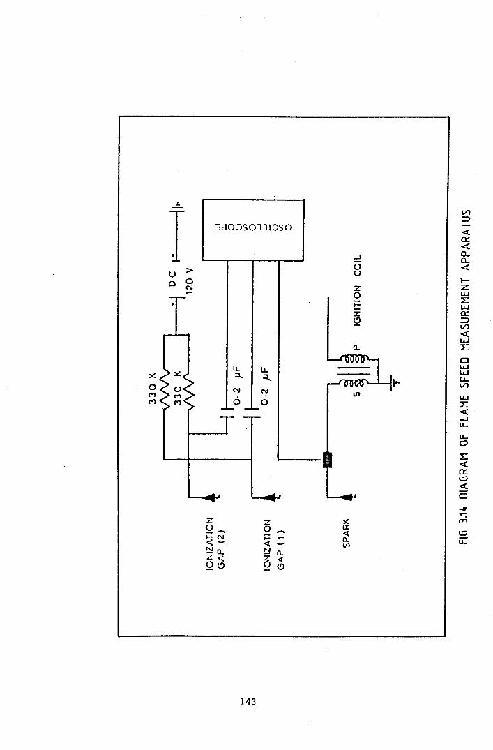
- Vl
I ::>I-3dO:JSOlll:JSO «et:-ca..J a.
0 «> uI-
UCl 0 z ZN
IJ..J.- 0 :EE IJ..JZ et:~ ::>
VI«IJ..J
a. :EClIJ..Ju, u,IJ..J:.:: :l... ~ II- a..VI0 N NIJ..JM
0 1:M 0«-Ju..LL.0
1:-cet:l:J-cCl
..:t
...-::.:: ",z z
Q-- 0 0:l:J,.. ~.....N t= .... a.. u.. .et ...... et Vl~a. N a.
Z~~ etQc> 0
143

8
I ENGINE A I"....I1II
(Yl
~vIlSI
6.......,t-ZWzWocUZ.....~0...Ju,
4 >-ID~0...Jm
2
--UNBURNT INCREMENTS
36~ 42~CRANK ANGLE (DEC. A.. 1. D. C )
FIG 3.15 COMPOSITION INCREMENT CURVES FOR ENGINE A
144
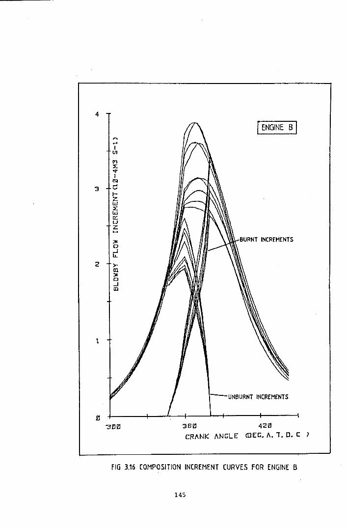
4
[ENGINE B I,.......Il1J
(Ylx'¢
IlSI....
'3 .....t-Zw~W0::uZ....~0..Ju,
2 >-Dl~0_JIII
t
-UNBURNT INCREMENTS
36~ 42~CRANK ANGLE COEG. A. 1. C. C ')
FIG 3.16 COMPOSITION INCREMENT CURVES FOR ENGINE B
145

16
I ENGINE 0 I,...r4
IVI
(TlLo;tIlSI....
12 ...,!-ZWLW~UZ......
3t0 BURNT INCREMENTS_lLL
8 >-m;;t0.Jm
--UNBURNT INCREMENTS
36~ 42~CRANK ANGLE COEG. A. 1. D. C )
4
FIG 3.17 COMPOSITION INCREMENT CURVES FOR ENGINE 0
146
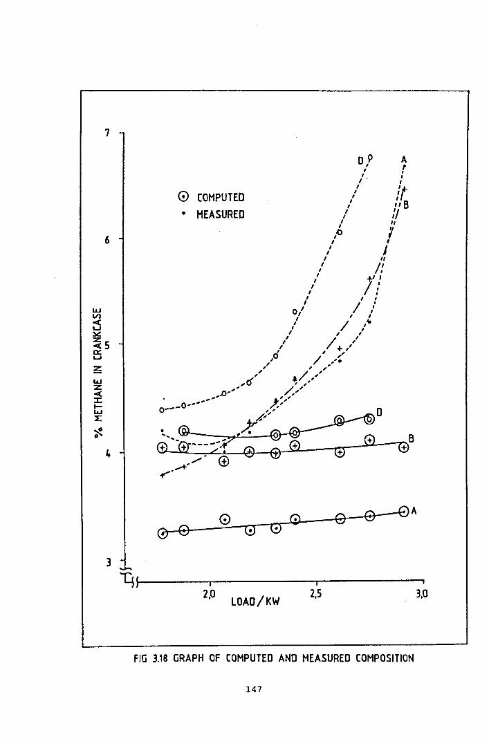
wVl~'-':lIc:
~Sa::'-'~WZ-c:::r:I-W2:
~o
7
6
4
3
os>,
o COMPUTED
• MEASURED
Ar,,,/ts",'I
"(,I"j,'
+.I'/;I ,
/ ,.,I ,
/ ",-I ,
/ + ,/, ,I'/ ,,_, "
~/",, ./",'
D
y~----~------~--------~2,0 2,5 3,0
LOAD/KW
fiG 3.18 GRAPH OF COMPUTED AND MEASURED COMPOSITION
147

--
,
/POINT OF (aNT ACT
--
II,
I
J
270 TOC 450PRESSURE DISTRIBUTION IN THE RING PACK
FIG 3.19 DIAGRAM OF COMPRESSION RING SEALING
148

Chapter 4 The Investigation of Oil in the Top Ring Zone.
4.1 Introduction
4.1.1 Lubricating oils and crankcase gas.
Blowby occurs as a result of the differential pressure between thecombustion chamber and the crankcase, by passing through the pistonring pack. It is in this region that the oil is performing its mostdemanding task - the maintenance of lubricated contact between thepiston rings and the cylinder liner. The oil is working underconditions of rapid motion, changes in both velocity and direction ofthe piston assembly, leading to high shear rates, temperatures andpressures, and the encroachment of hot blowby gases. Poor lubricationand high wear lead to excessive blowby, and so the quality of theoil's performance indirectly affects the nature of crankcase gasformation. The interaction between blowby and the oil on the cylinderliner is therefore very important, as it can reduce the effectivenessof the cylinder liner lubrication.
This section of the research project investigated the nature of thelubrication oil in the cylinder bore, at the point where the topcompression ring is at the limit of its travel (TDC). This region hasthe maximum wear of the cylinder liner. As a prerequisite to detailsof the research, the nature of the oil used is introduced.
Modern automotive multigrade lubricating oils are formulated from ablend of base oils and specific additives which, as a total package,are designed to cope with the demands of modern high performanceengines. The additives complement the properties of the base oils toprovide lubrication under a wide range of conditions. The oil has toperform the following main tasks:
(a) Lubrication of moving surfaces. The oil must prevent damagingcontact between paired surfaces,ensuring good separation under awide range of temperature and load conditions.
149
(b) Retain its chemical integrity whilst inhibiting chemical attackon the engine. The engine requires protection from bothcombustion and oil degradation products, and the oil package mustresist degradation under conditions of high temperatures,pressures and agitation.
(c) Cooling of high load areas. The engine bearings rely on oil asthe primary coolant - a fresh supply of oil is provided directlyto the region of highest load, cooling all the bearing surfaces.Secondary systems such as water cooling only affect the generaltemperature of the engine assembly.
(d) Resist thermal degradation and fractionation. The start uptemperature can be -300C or lower in cold climates, withassociated sludging problems. The normal sump temperature is 80to 950C with cylinder liner temperatures of up to 2000C , andaccompanying exposure to hot combustion gases of approximately9000C.
The modern multigrade engine oil contains a base oil mixture deriveddirectly from the distillates of a blend of crude oils. Theperformance of the base oil has shortcomings in several areas, notablythe temperature-viscosity and extreme temperature characteristics.The use of additives improves performance in these areas, and extendsthe range of other areas. The additive package in an oil formulationconsists of several chemicals, many of which enhance the properties ofthe base oil in more than one way. However, the single most importantrole of any additive is that it is compatible with both the base oiland the other additives present in the package. The properties of theadditives fall into one or several of the following classifications:
Detergent/Dispersants are designed to prevent the contamination ofmetal surfaces by oil impurities and breakdown products (e.g.carbon). This is achieved by surface adsorption onto the engineinternals, thereby creating a non-polar hydrocarbon layer above the
150

metal surface; and also by adsorption onto the impurities, enablingthem to remain in suspension within the oil matrix. This process issimilar to the action of detergents in aqueous solutions.
They fall into two major chemical groups; organic metal salts, with ahydrocarbon molecule associated with a metal anion via a polar groupin its structure; or ashless polymeric compounds with varying degreesof polar activity. These additives are selected for their ability to:
- Hold contaminants in suspension.- Coat engine internals.- Resist foaming or sludging.
Corrosion Inhibitors prevent corrosion of the engine, which can occuras the result of acid attack by combustion products dissolved in theoil. These additives usually have an anti-oxidant ability. They havetwo main modes of action - adsorption onto the metal surfaces to forma protective layer against chemical attack, and chemical reactionwithin the oil matrix to neutralise corrodant molecules. The latterfunction often includes the use of hydroxides and carbonates ofcalcium, magnesium or barium to eliminate acid molecules, or organicsulphur, nitrogen and phosphorous molecules to eliminate free radicalattack. These additives are selected for their ability to:
- Resist the promotion of the oxidation of oil and additives.- Remain in suspension both before and after reacting.- Control the pH of the oil over a large temperature/life range.- Be effective, without yielding a high ash content in the oil
(alkali metal salts).
Antioxidants are added to discourage oxidation of the base oil andadditive package - which leads to an increase in viscosity, sludgingand acidity by oxygen (from the crankcase, blowby gases anddissolved in the oil) and also by oxidising impurities. They alsocomplement the corrosion inhibitors, in that they prevent oxidation ofthe alloys within the engine. All antioxidant additives possess a
151

degree of corrosion inhibition, and vice versa. This categoryincludes the dithiophosphates and hindered phenols. The mechanism ofchemical reaction in solution is usually complex. These additives areselected for their ability to:
Inhibit peroxide free radical oxidation reactions.- Complement the corrosion inhibitors and overbase additives.
Viscosity Index Improvers are designed to maintain constant viscositythroughout the service temperature range. They are polymers, commonlymethacrylates, whose molecular structure uncoils in response to inputof thermal energy into the bonds with increasing oil temperature, thuscounteracting the coincident thinning of the base oil. At the hightemperatures developed locally at loaded surfaces within the engine,VI improvers undergo transient viscosity reduction under sheer stress,as a result of the elongated molecules becoming aligned with the oilflow. This reduces friction and allows the rapid removal of heat. VIimprovers are selected for their ability to:
- Complement the base oil's temperature/viscosity properties.- Withstand chain scission under extreme loads and temperatures.- Withstand oxidation.- Remain in suspension under all conditions.
Pour-Point Depressants prevent low temperature sludging and waxing ,thus assisting the start up and cold running of the engine. This isachieved by adsorption on the surface of organic precipitates, orpreventative co-crystalisation with wax molecules. Modern pour-pointadditives are polymer methacrylates and also have dual VI roles.
Extreme Pressure additives assist in the lubrication of movingsurfaces as the properties of the base oil tend towards breakdownunder peak load conditions. Their mode of action is viaadsorption/reaction with the loaded surfaces to give a surface layerwith a low shear strength, this effect is accelerated with increasingtemperature (i.e increasing resistance to load).
152

4.1.2 The Mechanism of Cylinder Liner Lubrication
Engine oil plays an important part in the operation of the piston andpiston rings by lubricating the cylinder liner wall. A properlylubricated cylinder wall is vital to reduce the wear of both piston,piston rings and liner. The oil film reduces friction between thepiston assembly and the cylinder wall, thereby reducing power loss.However, the amount of oil supplied must be carefully controlled. Toomuch oil results in an increase in consumption, as the excess oil isflushed into the combustion chamber and subsequently burnt. This isalso undesirable as it increases combustion chamber deposits,increases exhaust hydrocarbon emissions and provides carbon depositswhich can clog the piston rings and piston land leading to pistonscuffing. Too little oil leads to breakdown of the oil film, theincrease in friction and temperature leads to excess wear and scuffingof the piston assembly and the cylinder liner, and eventually tocomplete siezure.
Cylinder liner lubrication is dependent on the operation of the pistonrings. The oil reaches the cylinder wall by a combination of directsplashing of the sump by moving engine components, and also indirectoiling as a result of the small end oil feed or oil used to coolpiston crowns. The mechanism for individual engines varies dependingon the design of the lubrication system. Once the oil has reached thecylinder wall, it is then spread over the travel of the piston by theaction of the piston rings.
The main mechanism of oil film formation is that of hydrodynamic wedgeaction which occurs as a result of the sliding velocity of the pistonrings combined with a ring running face profile which generates ahydrodynamic wedge (Fig 4.1). Careful design of the piston ring outerprofile promotes hydrodynamic lubrication in the mid-stroke region ofpiston travel, where the sliding velocity of the piston is sufficientto force the 011 to separate the ring and liner surfaces. The oilsupplied to the cylinder wall is evenly distributed by this action,whilst any excess oil is returned to the sump via the oil control ring
153

and oil drain holes in the piston wall. Towards the limits of thepiston travel, the sliding velocity decreases thereby reducing the oilfilm thickness. However, at this stage in the cycle, the piston ringexpands towards the liner as the hydrodynamic pressure decreases. Theoil trapped between the piston ring and the cylinder wall iscompressed, and therefore pressure is developed. This squeeze effectdelays the collapse of the oil film and the expansion of the pistonring to touch the cylinder wall as the piston approaches, reaches, andpasses TDC. A well designed piston ring pack will ensure that thecombination of hydrodynamic and squeeze effect mechanisms willlubricate the cylinder wall throughout the whole combustion cycle.
The oil film formed by the action of the piston rings is notnecessarily continuous, nor is it always even. Considerable work hasbeen done to establish the nature of the oil film layer.
Early research concentrated on friction and establishing the mode oflubrication. The electrical resistance of the oil film was measuredin running engines (Fig 4.2) giving a qualitative measurement of thefilm thickness (Ref 4.1). This shows the breakdown of the oil filmtowards TDC, corresponding to the loss of full hydrodynamic action.The early theoretical studies concentrated on the piston ring profilefor ideal operation, and this has been extended to cover the combinedoperation of the whole ring pack •• Recent work has included the roleof the oil control ring in limiting the supply of oil to thecompression rings, and the extent that full hydrodynamic operation hasbeen reduced in modern engines as a result of attempts to reduce oilconsumption (Ref 4.2). The hydrodynamic lubrication mechanismcontrols the movement of the oil within the ring pack once supplied bythe oil control ring (Refs 4.3, 4.4).
Wear of the cylinder liner and the piston ring running face occursthroughout the life of the engine. During the running in period, theformation of the oil film is incomplete as a result of the mechanical"bedding in" of the cylinder components. This includes thecomplementary smoothing of both piston ring and liner surfaces,
154
between which the hydrodynamic oil film is eventually fullygenerated. Throughout the remainder of the engine's life wear occursmainly at the dead centre positions, corresponding to the breakdown ofthe hydrodynamic oil film and direct piston ring contact with thecylinder wall. This process is encouraged with engine age, as thepiston rings lose their springiness as a result of thermal effects,and fatigue due to their confinement within the cylinder. Hence, asthe engine ages, weaker piston rings find it difficult to follow anincreasingly worn cylinder profile. The ability of the rings togenerate the oil film decreases correspondingly, and blowby, oilconsumption and further wear occur as a result.
The wear of the piston rings and cylinder are the major cause of theincreasing blowby with increasing engine age. The wear of thecylinder wall near to the TDC position of the top ring compromises itsability to seal. High speed engines rely mainly on the top ring tocontrol blowby, because the pressure drop across the top ring islarge. This is because the pressure above the top ring is maintainedby the fast cycle time. In slower engines there is more time withineach cycle for the blowby gases to pass through the ring pack, and thepressure drop across the top ring is smaller. In high speed engines,it is important that the top ring provides an adequate seal, with theother compression rings playing a lesser role. The performance of thetop ring in the region of TDC determines the quantity of blowby toreach the other compression rings.
The conditions that the top ring, and any oil film lubricating andsupporting it, undergo at TDC are severe because the combustionprocess creates an agressive atmosphere of hot gas at high pressure.This, combined with the high temperature of the upper cylinder linerand piston crown provides a hostile environment for the lubricatingoil. The composition of the oil film within this region is largelyunknown, but it has been proposed that a standing ring of oil formsabove the limit of travel of the top ring. This oil will be subjectedto the agressive, hot combustion products, and forms the majorcomponent of the oil film lubricating the top ring at the limit of its
155

travel (Ref 4.5). The quality of the top ring oil controls thelubrication, wear, and therefore blowby of the engine. The supply offresh oil to this region is a compromise between adequate lubricationand reducing oil consumption. Modern engine designs use tightercontrol of lubrication by the oil control ring to reduce oilconsumption (Ref 4.4). This will also reduce the circulation of oilto and from the top ring zone. Oil is transported to this region bythe top ring on the upward stroke of the piston. Once exposed to thecombustion gases it will be partly removed by burning or evaporation.The remainder will eventually recirculate back down the cylinder walland return to the sump.
Recent research by Richard (Ref 4.5) has considered the nature andretention time of the top ring oil in a Petter AVB engine. The topring oil was extracted during normal running from a capillary hole inthe cylinder wall. The non-volatile magnesium content of both thesump and top ring samples was used to establish the amount of oil thatwas recycled from the top ring zone. This indicated that the majorityof the oil was lost, with only 42% returned to the sump on average.
4.2 Experimental.
The technique adopted by Richard (Ref 4.5) was considered ideal forthe investigation of the nature of the oil lubricating the pistonrings in the Villiers engines used in this work. The simple design ofthe air cooled single cyUnder engine allowed easy modification andaccess to the top ring zone of the cylinder liner. The natural gasfuel was also favourable, because there was no possibility of fuelcontamination of the oil samples (this is a problem with dieselengines).
The object of this experiment was to analyse the top ring oil, withthe aim of examining the lubrication of the compression ring as itpasses through TDC. The oil found in this region is subjected to theseverest conditions, which also corresponds to the greatest wear.
156

A sample hole was carefully drilled in the cylinder wall of engine A
at the point opposite the limit of travel of the top ring (Fig 4.3).
This engine was chosen because of its relatively unworn components
which allowed good development of hydrodynamic lubrication with
minimal b10wby. This combination was likely to produce the best oil
samples with the minimum of impurities such as carbon. The actual
height of the hole was selected to to ensure that oil from the upper
edge of the top ring was sampled. The hole was positioned on the
thrust side of the cylinder bore, perpendicular to the crankshaft axis.
The 1 mmsample hole in the liner had no restriction device and the
oil passed through a brass fitting inserted into the cylinder block.
The fitting located a 10 cm length of 4 mm internal diameter copper
tube which carried the sample to the collecting vessel. The length of
copper pipe was made as short as possible to prevent the oil from
burning onto its interior wall.
The initial work attempted to establish an adequate trap to collect
the oil sample. The trap had to de-mist a fast flowing gas whilst
cooling and trapping the oil. The initial runs showed that the main
problem appeared to be that the flow of gas was fast enough to force
the oil vapour through the system before it had condensed onto the
inner surface of the sample vessel. This led to a loss of sample
vapour. The first trap was not very efficient, collecting only a
trace of oil in one hour's running. The technique of collecting a
sample of top ring oil was re-examined. The important components for
a successful trap were considered to be:
(a) Water cooling of the container. This ensured the rapid cooling
of the oil vapour from the hot gases passing through the sample
trap. The continuous flow of hot gases from the engine, combined
with direct heat transfer from the cylinder head through the
collecting tube, rapidly warmed the collecting vessel, thereby
hindering the condensation of the oil. The cooling of the
container also reduced the chance of any thermal degradation of
the sample.
157

(b) A relatively large volume condensation trap. This would contain
a large amount of the condensation medium described in (c) and
would allow a longer vapour contact time as a result of the drop
in gas velocity. Better heat dissipation would also be expected •.J'.
(c) A condensing medium within the trap to collect the cooling oil
vapour. The drop in gas velocity as a result of the sample
mixture expanding into the condensation trap was not sufficient
alone to allow the oil vapour to condense. Impingement plates
were also not adequate. It was deemed necessary to pack the
condensation trap with as much condensation medium as possible.
The ideal properties for the condensing material included a high
surface area with good thermal conductivity and chemical
inertness. Various materials were tried, including glass and
wire wool, lead shot, carbon fibre matting and glass beads.
(d) positioning the trap as near to the engine as possible. The
sample probe was not cooled and the connecting pipe between the
engine and the cooler sample container was kept as short as
possible to prevent the oil vapour from burning onto its inner
wall. Ideally, the collecting pipe should be water-cooled from
its connection to the cylinder head. However, with the air
cooled Vill1ers engine this was not possible without extensive
modifications to the engine assembly.
The first successful trap (Fig 4.4 left-hand diagram) collected oil
with natural gas as a fuel. The gases passed through a brass silencer
fitting into the trap packed with steel wool. These runs were at a
load of 2 kW over a one hour period with frequent changes of the
cooling water in the cooling bath to ensure that the condensation trap
was kept at the lowest possible temperature. The second series of
experiments were run using a collecting system which had been improved
to the later version (Fig 4.4 right-hand diagram) with continuous
cooling water.
158
4.3 Results and Discussion.
The engine was run for 1 hour periods, with at least 1 hour shutdownbetween sampling runs. This was because the extent of the oilextraction was difficult to assess, and until the calculations werecompleted, no apparent rate of oil removal could be determined andcompared against the estimated rate of oil supply to the top ring.The oil used for these tests was a proprietary 20W/50 multigrade oil,as used for all the experimentation on blowby.
Unlike the reported oil from the Petter AVB (Ref 4.5), the traps usedin this work collected a mixture of oil and water. The presence ofwater can be explained by both the quality of the condensation processby the water cooling of the collection system, and the large amount ofwater in the combustion products because of the high hydrogen contentof the fuel (CH4) when compared with diesel. The sample alsocontained carbon, flushed out of the combustion chamber by thesampling process. These samples required working up before analysis.The procedure devised was:
(a) Gentle water evaporation at 500C overnight in a dark oven.The low te~perature was designed to slowly remove the waterwithout chemically degrading the oil sample.
(b) Extraction in n-pentane. This was chosen because of itsnon-polar solvent potential, and also its low boiling point(36 °C).
(c) Centrifuging of pentane insolubles from the extract. Theseconsisted mostly of carbon, and some oil breakdown products.
(d) Evaporation of the pentane to leave an oil sample. This wascarried out at room temperature in a dark, well ventilatedenclosure.
159

In all cases, the product oil sample was a dark brown viscous liquid,of great subjective difference to the corresponding sump sample. Theoil had been subjected to a fundamental change in its properties byits residence in the top ring zone. Several samples were collectedfor analysis, the extraction rate was approximately 0.5g per hour ofrunning. The oil samples were analysed by the following techniques togive the results presented in Table 4.1.
Total Base Number (TBN). This is a measure of the base content of theoil formulation. It is defined as the quantity of mineral acid(expressed as the equivalent number of milligrams of PotassiumHydroxide) required to neutralize the base content of one gram ofoil. The analysis technique (IP 177, Ref 4.6) is a titration of anoil sample by HC1, using suitable solvents. The end pOint isdetermined potentiometrically.
The results show that the TBN of the sump oil has reduced slightly,indicating that there has been some reaction between acids from thecombustion process and the oil. However, there is a dramaticdifference between the sump oil and the top ring oil. The top ringoil has suffered from severe deterioration of its alkali reserve.
Total Acid Number (TAN). This is a measure of the acid content of theoil, as a result of the acids introduced by combustion products. Itis defined as the number of milligrams of Potassium Hydroxide requiredto neutralize the acids in one gram of oil. The analysis technique(IP 177 Ref 4.6) is similar to that for TBN, using KOH titrant.
The results show that the TAN of both the new and the sump oil iszero, indicating that there is no free acid present within the oil.The top ring oil has a high TAN however. This also coincides with avery low TBN, and the top ring oil has an excess of free acid which ispotentially corrosive.
Viscosity Index Improver (VII) mean molecular weight. This wasdetermined by gel permeation chromatography (GPC), which compares the
160
molecular weight of standard chemicals to that of the sample by theirrelative position within the chromatographic column.
The results show that the VII content of the oil formulation hasdecreased by 5% in 40 hours within the sump, but that its presence inthe top ring oil is reduced to 50%.
Simulated distillation by gas chromatography. This involves thedistillation and analysis of the oil sample by a temperatureprogrammed GC. The analysis is presented as a weight within eachtemperature band.
The results show that the lighter fractions of the oil, which appearearly in the distillation have been removed from the top ring oil.
Oxidation onset by PDSC. This involves the forced oxidation of theoil sample within a calorimeter. The exothermic reaction associatedwith the oxidation of the oil only occurs after the anti-oxidantadditives have been exhausted.
The results show that the top ring oil has zero oxidation stabilityand is very poor when compared to both the sump oil and new oil. Thisindicates that the antioxidant additives have been completely consumedin the top ring oil.
Oxidation by IR spectroscopy. This involves analysis of the sample todetermine the extent of carbonyl species present.
The results show that no oxidation (as measured by the formation ofcarbonyl bonds) has occurred in any of the samples.
The oil in the top ring zone is subjected to the high temperatures andpressures experienced by the combustion chamber. There will be atendency for the oil to burn, a phenomenon reduced by engine designersby limiting the quantity of oil reaching the top ring zone, usually bymodifications to the performance of the oil control ring. However, a
161

certain amount of oil reaches the top ring zone, in its role oflubricating the top ring. Not all of this oil is burnt, but it isotherwise modified by the conditions in this region. The oil is alsosubjected to chemical attack from the combustion gases, under thefavourable conditions of high temperature and pressure. The oilsampled in this work was collected from the region at the top of thetop ring at TDC. The oil in this region can be considered to besemi-permanent, forming a ring around the cylinder liner (Ref 4.7).Its properties are controlled by a combination of the conditions atthe top ring zone as it is partially consumed, replaced by fresh oilor returned to the sump.
The TBN and TAN results show that the alkali reserve of the oilformulation has been almost totally neutralized, and that a quantityof free acid is present in the oil. The acids will be partiallyneutralized by fresh sump oil supplied by the lubrication mechanism,but inevitably some must be transported into the sump. The free acidpresent in the top ring oil must be considered as a serious corrodant.
The oil has experienced thermal degradation which will alter theviscosity in two opposing ways. The lighter fractions of the oil willbe preferentially evaporated by the high temperatures involved. Thiswill tend to increase the viscosity of the top ring oil. This isillustrated by the GC distillation results. The longer polymermolecules present in the oil will undergo chain scission. This willtend to reduce the viscosity of the oil. As the analysis of the VIIimprovers shows, the content of polymer additive has been greatlyreduced by its residence at the top of the cylinder bore.
The two results examining the oxidation of the oil indicate that thereis no remaining anti-oxidant additive in the top ring oil. However,no carbonyl oxidation is present. This suggests that the lack ofanti-oxidant is due to thermal degradation rather than chemicalreaction.
162

The oil sampled by this technique is subject to a dynamic transportsystem and is partially returned to the sump by the action of thepiston rings. By comparing the measurements for top ring and new oil,it is possible to determine the degree to which top ring oil has beenreturned to the sump. This can be expressed as a percentage as shownin equation 4.1, using the results given in table 4.1. For the TBNresults the top ring oil content in the sump (x) is:
(1.36x + 7.5 (100 - x» I 100 - 6.95 (4.1)
x - 8.79%
Similarly for VII analysis x - 10.00%
and for distillation profile x - 13.70%
These calculated results show good agreement for differing aspects ofthe oil formulation. The calculations above assume that the top ringzone is a region of significantly high chemical and thermal activitywhen compared with the sump, and that therefore all sump oildeterioration occurs as a result of the transport of top ring oil backinto the sump. This assumption is clearly valid, as illustrated bythe degradation of the top ring oil. However, antioxidant activitydoes occur within the sump, and oxidation life of 14 mins is acombination of both top ring and sump based reactions. By using avalue of x • 10% for the PDSC, an expected oxidation life of 20.7 mins(cf 14 mins) is derived. The difference can be explained by thecontinuing activity of antioxidants within the sump.
Section 4.1.2 outlined the basis of hydrodynamic piston ringlubrication. The oil control ring provides sufficient lubrication toallow hydrodynamic and squeeze mechanisms to support the piston rings,without excessive oil being burnt in the combustion chamber. However,the oil supply to the upper part of the cylinder liner, beyond thetravel of the oil control ring, is governed by the way in which thecompression rings distribute the oil film supplied. In order to
163

reduce consumption, the supply of oil is kept at a minimum, yieldingconditions where full hydrodynamic lubrication is compromised. As thetop ring approaches TDC, the deceleration results in the oil filmabove the ring being thrown onto the upper liner. This replenishesany oil lost at the top of the stroke due to evaporation, and providesa layer of oil above the normal travel of the piston ring (Ref 4.1).This ring of oil has been noted in photographic studies (Ref 4.7).The oil sampled in this work is formed as a result of this mechanism.The oil within this region is subjected to the severest conditions.
The combustion chamber temperatures are hot enough to induce bothevaporation and thermal cracking. In a high speed four stroke enginethe exposure time for evaporation is short relative to oilreplenishment by the piston on the unloaded exhaust stroke.
All the results given in Table 4.1 indicate that the top ring oil hasbeen subjected to severe thermal degradation, the only resulthighlighting a chemical change is associated with the TBN/TAN. Thelack of chemical degradation can be explained by the quenching of thecombustion within the combustion chamber, hence the top ring oil isuntouched by the flame front.
164

References Chapter 4
4.1 Department of Industry Report TRD 162, Piston and Ring Design 1974.
4.2 RUDDY B.L, DOWSON D, ECONOMOU P.N "A theoretical analysis of theTwin Land type of Oil Control ring" J Mech Eng Sci, Vol 23, 1981, pp5l-62
4.3 PARKER D.A, ADAMS D.R, "Friction losses in the reciprocatinginternal combustion engine" in Tribology - Key to the efficientengine. MEP 1982 pp3l - 39
4.4 McGEEHAN J.A "A survey of the mechanical design factors affectingengine oil consumption." SAE 790864.
4.5 RICHARD G.P "Lubricant properties in the Diesel engine piston ringzone." presented at the 9th LEEDS-LYON Symposium on Tribology, LeedsUniversity 1982.
4.6 IP177 Institute of Petroleum standards Part I 39th Ed. 1980.
4.7 GREEN A.B "Photographic recording of Dynamic Oil Filmcharacteristics in a Piston Cylinder Simulation rig." I.Mech Econference on Photography in Engineering, London 1969.
165

Figures Chapter 4.
Fig 4.1 Diagram of the hydrodynamic lubrication of a piston ring.Fig 4.2 Resistance trace between top ring and liner.Fig 4.3 Cross Section showing oil sampling system.Fig 4.4 Diagram of the two types of oil trap.
Tables Chapter 4.
Table 4.1 Comparison of the Properties of Top Ring Oil.
166

e0.~~Ilj ~'0 H Q) Q) Q).~ c: c c:>< :>.. 0 0 00 .Q Z Z Z
r-iU .~c: U) 00 0.~ P- III III b'~ c: c: III c:Ilj ~ .~ .~ c: .~
'0 Q) El El .~ J.I.~ II) Elx c: M qo 0.0 0 N r-i 0 0E-i
IJ1 4-1c: 0.~c: . II).~ ~ Q)Ilj II) .~El .~ ~Q) '0 dP J.I~ 0 lIP dP Q)>. 0 0 " 0.dP .Q r-i 0'> N 0
J.I0.
~ Q)c: .£:H Q) 4.JH 4.J rIPe- e 0 dP lIP 4-1
0 0 III 0 0dP U r-i 0'> III
c:0II)
CO .~Z r- J.II« Ilj~ 0 0 III 0.
El0U
III \0Z III 0'> M~ . r-i~ " \0 r-i
qo
r-i Q).~ r-I0 0 .QIII Ilj<, r-i 0'0 ~~ .~ c:
Q) 0 0 .~r-i N Io.l0. 0.El ~ El 0.Ilj Q) ::I 0U) Z U) E-i
167
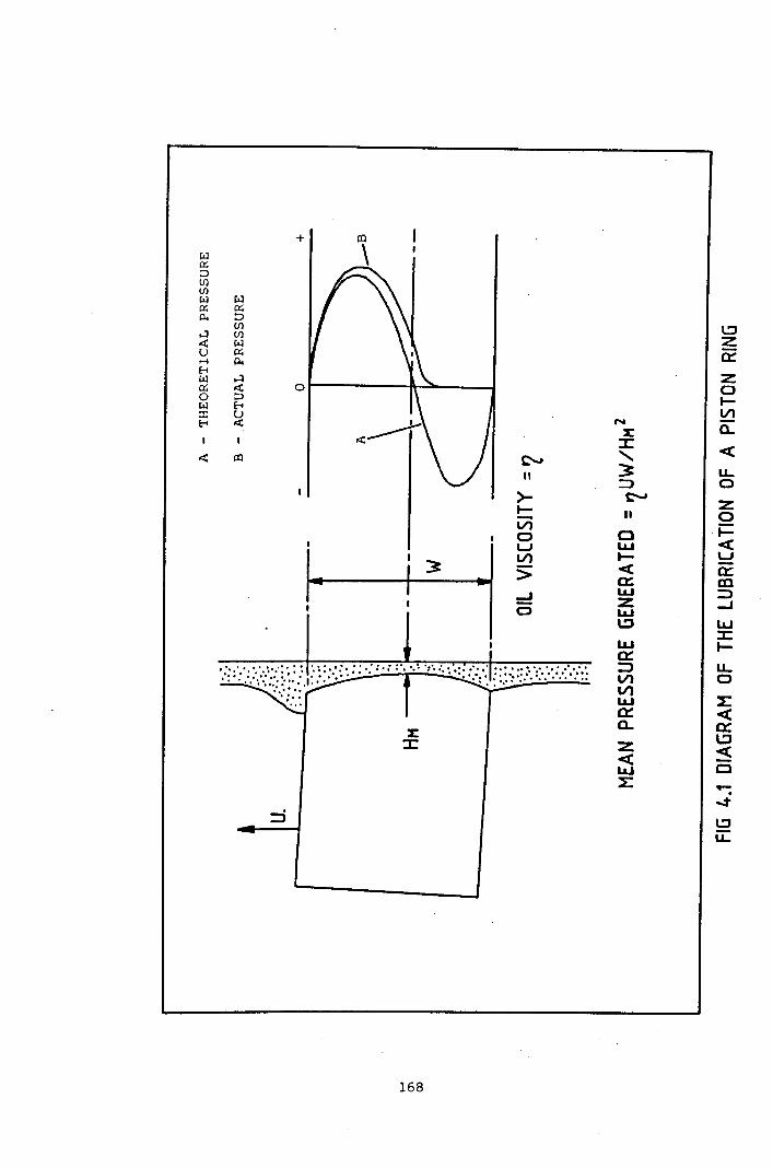
L:J~0::Z0l-V)
N a..:E
-c::z:<,
u...~ 3
0II =>
~ z>-0l- II
i=VlCl -c0I.&.J
Uw
I-0::
Vl -eCD
:> Cl::=>I.&.J-Id z
I.&.JLLJ
CJl::J ::z:I.&.J I-a::
u...::J0Vl
Vl~I.&.J -ca::0::a..l:Jz -c« CI.&.J
""":~~L:Ju...
=>
+W0::JU)(J)
wW0:0::Jp..U)
....:I (J)
~ W0:U p........
E-<HW ~0:
0 :JW E-<:r: uE-< ox:
~ al
168

0Nc-
L ~_J UJu, ~...J ...J
0 CJ
UJ0 Z..:t «I- LJ"'I
UJ l:J_J
0- ~L ~0 V) 0-W I.J..J
\ I.J..J 0a:: I-l.:JI.J..J ZOW CJ I.J..J"lCJ L&J
tTl I- <, 3I-
L&J UJ_J CDl:JZ UJ« U-c~ a::z I-
0 -c L&Jco a::: U·..-. U ZV) -cL I-:r: V)
0 V)
<, I.J..Ja:::UJ NW .Jz« ~t- OV)
u,
V)
/J\\d q\I.J..J N .- Lna::: d 0 0t- O 0 0U 800 .-« a .-I-
..-Z0W
169

UJ9:a..UJ....Ja..L«V1
0:~------_lou
Ib
_j
uClt-t--ezot-!Qo,
::E:t-szoi=-VIoa..LLJ-Io::E:LLJ-Ia..L-cV1
",
~
!:2u,
170

1
... VIW -.A Q_, 0 00(
5 0 1&.1
0)t CD
er: z VI
w 0 VI... eo 00(_,00( \.:l)t
I II
I I I I I
:c1LJo~- __a::1.::Ju.. Z
ILJ
I I I I, I I
I II
171
I I I
I I I
II I I
I I
I II I I, ' I I
I I
I II I
I I I II
0..<0::t-_J
ou..oVllLJ0..>-t-o:3t-lLJ::ct-u..oL-c0::I.!J-cCl
..:t
...:t
I.!Ju,

Chapter 5 Discussion.
5.1 Conclusions from the study of blowby gas.
The literature on crankcase gas, engine emissions and piston ring
operation reviewed during the course of this work has revealed that
several authors have commented that crankcase gas contains a large
amount of fuel (Ref 5.1, 5.2, 5.3). Very little investigation of
the nature of crankcase gas formation has been done, mainly due to
the adopted automotive technique of crankcase gas recirculation.
Indeed, the major problem with both open (air bleed into crankcase)
and closed recirculation systems is the oil mist from the engine
condensing in the induction system, or other cool areas in the
engine. However, the adoption of more stringent emission
legislations in the automotive industry is likely to encourage more
research into crankcase hydrocarbons. This is because crankcase
ventilation, unlike cold start fuelling or evaporative emissions,
does not readily lend itself to computer control.
The experimental engine work used a single cylinder Villiers C-30
engine to quantify the composition of the crankcase gas obtained
from engines of various age and wear conditions. The crankcase
system on this engine is simple, with no recirculation of the gases,
and a straightforward breather. This type of crankcase ventilation
is common on generator engines. The main conclusions that can be
drawn from this part of the work are:
(a) The fitting of a new piston and rings in a badly worn engine
reduces blowby, but not down to the level of a new engine
assembly. In this respect it is important that both the piston
and the rings are replaced. New rings in worn piston grooves
would not seal effectively. The partial reduction in blowby
can be attributed to a better seal by the piston rings, with
the measured blowby passing mainly through the piston ring gaps.
172
(b) Blowby flowrate increases with load at a rate which is greaterfor worn engines. particularly at higher loads (Fig 2.15). Thelack of rapid flow increase with load for the newer engines.despite the increase in combustion chamber pressure indicatesthat the blowby process is limited by the quality of pistonring seal. The older engines show breakdown of this sealleading to much greater flowrates.
(c) The fuel content of blowby increases with load. despite theincrease in inlet fuel composition with load. This feature iscommon to all of the engines used. and the fuel content of theworn engines is higher than that measured for newer engines.The magnitude of this difference is not large. but whencombined with the higher blowby flowrate. yields a greater lossof unburnt fuel gas. The trend of fuel blowby was similar forall fuel gases considered.
(d) The CO2 content of the blowby showed no conclusive trends,but its mechanism appears to be independent of the fuel gasblowby. The concentration of CO2 in the crankcase remainedwithin the 1% to 2% range for all engines at all loads. Theincrease in CH4 content with load did not appear to influencethe CO2 content.
The calculations confirmed that the mechanism of crankcase blowby isthrough the piston ring gaps at low load and/or low wear. withanother mechanism. piston ring seal breakdown. present underconditions of heavy load and poor liner condition. The experimentaland calculated results have also shown that the fuel content of thecrankcase occurs as a result of more than one mechanism. The StaticPiston experiment is limited in that the b10wby environment has beengreatly simplified in order to provide the basis for a simple seriesof calculations to compare with the experimental data. A far moredetailed treatment is required to further investigate the blowbymechanism. including corrections for the gases present and asophisticated model of the combustion process.
173

5.2 The use of small engines in the Biogas Industry.
The purpose of using internal combustion engines in the BiogasIndustry is to utilise the fuel produced from the digester toproduce high grade energy. Other applications, such as irrigationpumping may be considered. This work has shown that although thelarge scale digester engine is successful, the small engine has yetto be fully developed. In analysing this observation the follOWingconclusions can be reached which outline the present status of thetechnology.
(a) Most small biogas engines are derived from generator and/orautomotive designs, and therefore some design compromises arepresent. The low demand for this application results inengines (converted for natural gas) remaining largelyundeveloped and unmodified by the engine manufacturers andsuppliers. The use of a Biogas engine is tailored to the needsof the site concerned, concerted development has been hamperedby this and by the alterations in the electricity tariffs.
(b) Severe corrosion of copper based bearings is present in allengines where the fuel gas has not been scrubbed. This isshown in Figs 2.1 to 2.6 as the systematic removal of thebearing surface, which at Retford, resulted in the completedisintegration and disappearance of the bearing. Other enginewear problems, notably piston scuffing, have been reported.
(c) The need for the small biogas engine has yet to be fullyjustified, with high comparitive capital and maintenance costsmaking the production of electricity in this manner uneconomicin the current financial climate. The Biogas industry mustlook for a more viable use for their energy source.
In order to identify the future for this sector of the alternativeenergy industry, the motivation for the production and utilisationof Biogas must be considered.
174

There are two types of use for anaerobic digestion, the treatment of
an obnoxious pollutant, and the use of a material to produce a
useful fuel Biogas. Small digester owners in the former category
will view the Biogas as a by-product which they will endeavour to
use in a profitable manner. However, the viability of their project
will be related to the turnover of the digestion process itself, and
therefore the production and quality of the Biogas may suffer.
Certainly the concept of utilising prototype engine technology to
dispose of the Biogas will not appeal, because of the potential
maintenance costs and risk of system failure. A simple use for the
gas such as space (or digester) heating will be regarded
favourably. This category of user is typically:
- A small sewage farm.
- An industrial site with a pollutant requiring safe disposal.
The second type of user has installed a digester specifically to
produce gas at a long term profit. Under this approach, the
economic utilisation of the gas is of great importance. This
category is typically:
- A Third World farmer, who requires the biogas for cooking and
heating.
- A European farmer who adopts intensive farming practices.
- A small sewage farm.
The main recommendation for the Biogas industry is that engines
running on untreated Biogas should be altered to allow the use of
Aluminium-Tin based bearings and to avoid excessive H2S b10wby.
This approach is easier to implement than the alternative, the
provision of force fed lubrication. Such modifications could be
implemented during the conversion for natural gas fuelling, and
marketed as an option by engine suppliers.
175

5.3 Conclusions from the study of top ring oil.
The experimental work into collecting top ring oil has yielded veryinteresting results. The oil was a viscous liquid, which had beenseverely degraded by the action of heat from the combustionchamber. There were no signs of chemical degradation, and inparticular, no signs of oxidisation.
The longer chain polymer molecules had been pyrolysed by the hotgases from the combustion chamber, chain scission had reduced theirVII characteristics. This decreases the ability of the oil to coolthe highest stress areas at the surface of the piston rings. Theevaporation of the lighter fractions of the oil is likely to counterany deterioration in the viscosity of the oil at the top ring zone.However, the loss of VII additive is also important as the top ringoil returns to the sump.
The combination of the loss of anti-oxidant and the high acid TANcontent presents a serious corrosion threat. The implication isthat the cylinder bore wear experienced at the top of the strokecould be directly related to the corrosive lubricant present. The.combination of high temperatures. and pressures are ideal for thecorrosion of the cylinder liner.
There are other consequences related to the thermal breakdown of theadditive package. The oil will have reduced dispersant/detergentabilities, which leads to piston ring clogging problems andimpurities trapped in the ring zone. It is difficult to assess theperformance of the top ring oil, faced with the task of lubricatingthe top compression ring, with such a degraded additive package.
The top ring 011 recirculates back into the sump. The control ofthis process is governed by the supply of oil to the compressionrings. The design of future engines, and oil formulations may beable to improve both the quality of oil in this area, and alsoenhance the life of the cylinder liner. The transport mechanism
176

requires careful study to highlight the optimum method of oilsupply. The behavior of the oil additive package, particularly withengine life, should be studied to identify those additives atgreatest risk, and those with the greatest resistance.
5.4 Recommendations and Further Work.
Sections 5.1 and 5.3 have summarised the experimental results andthe implications for the use of small engines in the Biogas industryare outlined in sectio 5.2. This project has raised several areasof future interest. The main recommendations are:
(a) Further work is required to discover more about the chemistryof the top ring oil. The drastic change in the properties ofthe oil in this region imply that the piston ring and thecylinder liner are being lubricated by an organic mixture ofhigh corrosion potential, and depleted additive protection.
(b) An improved technique for measuring TAN and TBN was underinvestigation at Leicester Polytechnic. The need for a moreaccurate and consistent analysis technique was highlighted bythe difficulty in analysing the top ring oil samples.
(c) An investigation into blowby diversion, as first proposed byQuillan et al (Ref 5.4) may prove successful. This paperinvestigated the possibility of collecting the blowby prior toits entry into the crankcase. The basic engine modificationsrequired for such a proposal may be possible with a low volumeBiogas engine.
(d) A more coordinated approach to Biogas engine modification andutilisation is required. The future of the small engine in theBiogas industry relies on the commercial implementation ofengine modifications, which will improve the reliability ofBiogas generator systems.
177

References Chapter 5
5.1 PAYNE J.Q, SIGWORTH H.W "The composition and nature of b10wby andexhaust gases from passenger car engines." Proc 2nd Nat Air Poll Symp1952 Vol 2 pp 62 - 70.
5.2 BENNET! P.A et aL,.; "Reduction of air pollution by control ofemission from automotive crankcases." SAE Transactions, Vol 68, pp 514-536.
5.3 HASS G.C, SCANLIN J.R "The contreo1 of crankcase hydrocarbonlosses." In Vehicle Emissions Part II (Progress 1n Technology Vol 12)SAE 1968 pp 429 - 433.
5.4 QUILLAN R.D et a1 "Cleaner crankcases with B10wby Diversion." inVehicle Emissions Part II (Progress in Technology Vol 12) SAE 1968 pp434 - 450.
178
Appendix 1. Computer listings.
Computer program to curve fit Static Blowby data.
Program flow explanation.Program listing.
Computer simulation of blowby.
Program flow explanation.Glossary of symbols.Program listing.

Computer Program to curve fit Static Blowby Data.
Lines
10 - 30
40 - 70
100
Function
Defines FN(BB), a function of pressure (p) and crankangle (A).
User input of data points, into arrays (A), (p) and (BB).
80 Creates matrices for data handling of function parameters(C), blowby derivatives (D), and curve fit residuals (R).
90 Provides start parameters for the curve fit routine.
Starts a loop which is executed for each experimentalpoint.
110 Calculates the residual blowby (Measured blowbyCalculated blowby using FN(BB».
130 - 170
180 - 200
210 - 240
250
260
270 - 280
Calculates the blowby derivatives with respect to theequation variables, using the central differencestechnique, then closes loops.
Calculates the least squares solution to the derivatives,which are used as corrections to the numbers originallygenerated in line 90.
Checks that the change from the curve fit is stillsignificant enough to continue.
Increments the previous estimates.
Repeats curve fit routine if no solution is yet found.
Prints solution if the curve fit is complete.

Computer listing for curve fit program.
10 DEFFNRB(P.A);Pl,Al:Pl=P-l;Al=ABS(A-360)20 FNBB=Pl*(C(I.1)+C«2.1)*Pl+C(3,1)*Al)*EXP(-C(4,1)+Al)30 Ft,lEtW-10 INPllT"tlO OF POINTS TO BE ENTERED";N50 DIHA(tJ),P(t~),BB(N,I):PRINT"INPUT ANGLE,PRESS AND BLOWBY"60 FORI= 1ron. PRINT"POINT"; I, : INPUTA( I), P( I), BB( I)70 NEXTI80 MATC=ZER(4,l):MATD=ZER(N,4):MATR=ZER(N,1}90 c (1. 1 ) =BP.( 1, 1 ) / ( P ( 1 ) -1 ) ; C( 4, 1) =LOG ( C( 1, 1) *(P (N ) -1)/BB (N, I) )
/(A(H)-;lt~O)100 FOR 1=1TO:~110 H(I,l)=BB(I,l)-FNBB(P(I),A(I»120 FOR.1=lT0413 0 C ( .r . 1 ) :: C ( J, 1 ) + 1E - 6140 (l,J)=FNBB(P(I),A(I})150 C ( ..1 • 1 ) ;:C ( J, 1 ) - 2 E - 6160 D(I,J)={D(I,J}-FNBB{P{I),A(I»)*500170 C(J, 1)=C(J,1}+lE-6:NEXTJ:NEXTI130 t-i/\ TT= TRN ( D)l~O MATE=T+D200 MATDC=lNV{E}*TtR:MATPRINTDC210 Q=O220 ronr . 1T04230 IFABS(DC(I, 1»>lE-4THENQ=1240 t-lEXTI250 MATC=C+DC260 IFQ::l1IlEN100270 PRHIT"COEFFICIEt-lTS"zco M/\TPRIt~TI:

Computer program to simulate piston ring blowby.
The blowby program is written in BASIC and is menu driven allowing theinput, manipulation and display of pressure and blowby information.It is designed to run on a PET 32k microcomputer fitted with the JJ
Instruments PD4 plotter software chip. The program is specific to theVilliers C30 engine, but can be used to create new data files forextending blowby work. All new files should have four characters,representing engine type and load (e.g engine A at 2.24 kW - A224).
Lines
180-200
210-220
230-320
330-340
350-370
380-545
550-640
650-670
680-760
Function
Routine to activate JJ instruments PD4 plotter chip.
Defines major data handing arrays and program constants.
Main menu display. Uses OP as the input to initiateprogram flow.
Initialises the main program subroutines, based on themain menu alternatives and includes a failsafe return.
Soft break of program.
Pressure data input menu including failsafe inputprotection. Counter PX returned to zero.
Input routines for pressure data for tape, disk, andmanual entry into array P(I).
Examines pressure array P(I) and establishes the maximumpressure PX.
Examines the pressure data input string RN$ to determinewhich engine is involved. Allocates the calculation

770
780-790
800
810-900
910-930
940-980
990
1000
1010-1020
1030
1040-1070
coefficients Al, A2, A3 corresponding to that engine (seeequation 3.2 and Table 3.2).
Registers that pressure data is present K(O) - 1, andzeros blowby calculation flag K(l) - O. Returns to themain menu via line 340.
First of two routines associated with the plotting menu.Line 780 checks that pressure data has been entered(Option 3 on main menu).
Checks that blowby has been calculated (Option 4 on mainmenu) •
Plotting menu display. Uses PP as the input to continueprogram flow.
Initialises plotting routines, or returns to main menu.
Start of the plotting routine. All commands prefixed byan exclamation mark (e.g !HO, :MA) are unique to theplotter and are used by the plotter chip located in thecomputer board extension socket.
Sets flag K(4) to 1 to initiate partition curve plottingonly. Moves to blowby plotting routine.
Sets flag K(3) to 1 to initiate axis plotting.
Checks for pressure data and blowby calculation prior toblowby plot.
Sets scaling counter MX to max flow counter FX and thenmoves to scaling subroutine at 1830.
Selects blowby plotting routine based on flags K(3) and

1080
1090-1130
1140
1150-1190
1200-1230
1240-1270
1280-1320
1330-1390
1400-1470
1480-1550
1560-1630
1640-1700
1710-1770
K(4). Returns to plotting menu after completion.
Sets constants and print string A$ for blowby axis plotroutine.
Pressure plotting routine. 1090 sets flag K(3) for axes,1100 checks KCO) for pressure data, 1110 sets scalingcounter MX to a function of max pressure counter PX andthen moves to scaling subroutine at 1830. Returns toplotting menu after completion.
Sets constants and print string A$ for pressure axis plotroutine.
Draws X and Y axes.
Labels Y axis.
Labels X axis.
Numbers X axis.
Numbers Y axis using scaling factor II generated fromscaling subroutine.
Plots blowby increment curve using values from FCI) andscaling factor II.
Plots unburnt fraction using values from FICI).
Plots burnt fraction using values from FECI).
Plots pressure curve using values from PCI).
Labels graph with engine and load.

1780-1930
1940-1997
2000-2010
2020
2030
2040
2050
2060
2070
2080
Scaling subroutine uses MX as a counter derived from thedata to be plotted. The calculation allows for out ofrange faults and user adjustment of scales for graphsuperimposition.
Blowby calculation subroutine. Initially checks forpressure data using flag K(O) and if the calculation hasalready been done K(l).
Sets calculation variables to zero and opens calculationloop using loop counter I.
Establishes crank angle DA using loop counter I andgenerates DB (TDC - 360 and the piston position issymmetrical about TDC). Pressure is corrected to actualfrom absolute.
B10wby increment generated from equation 3.2 and storedas a whole number in array F(r).
Incremental volume calculated and stored in V(!).Accumuiated volume stored in V2.
Maximum incremental flow counter is compared.
If the flame has not reached the ignition point (see Fig3.13) then F(I) is all unburnt (- FI(I». Program movesto 2160.
3 -1Updates flame radius RF using flame speed of 36 m s •
Converts crank angle DA into radians and calculatespiston height H from TDC using equation 3.1. H is thenmodified by 3mm because this is the distance between thepiston crown and the top of the cylinder bore at TDC.

2090
2100
2110
2120-2140
2150
2160
2170
2180
2190-2260
2270
2280-2330
2340-2420
Checks to see if the flame radius RF has reached thepiston height H.
Calculates the distance that the flame has crossed thepiston crown.
Checks to see if the flame has completely engulfed thepiston.
Calculates the amount of piston covered by the flamefront as an angle BA.
Divides the blowby into burnt and unburnt fractions.
Calculates volume volumeand updatesfractionsaccumulator V3.
Restores PCI) and continues calculation loop from 2010.
Sets flag KCl) on completion of calculation. Increasescounter FX to whole number.
Calculates overall blowby flowrate and displays resultson the screen. Returns to menu on completion.
Checks flag KCO) for pressure data.
Displays pressure output menu.
Transmits pressure data PCI) to storage medium.

Glossary of symbols
AAAAIA$
B
BA
BRCC$DDADB
DCDIFXF(I}FE(I}FI(I)HI
IIK(I}L
LK$MMXNOPP(I}PPPX
Spacing constant in X axis plot.Crank angle in radians.Scaling constant for Y axis numbering.String used in coefficient determination andplotting routines.Coefficients from equation 3.2 used incalculations.Spacing constant in X axis plot.Ratio of piston crown coverage.Radius of flame front across piston crown.Spacing constant in Y axis plot.String used to number axes.Spacing constant in Y axis plot.Crank angle for increment.Angle away from TDC.Start angle for plotting calculations (300o).Increment of crank angle (2o).Counter for maximum flow.Array for flow increments.Array for burnt increments.Array for unburnt increments.Piston height.Used as a counter in all parts of the program.Modifier produced from scaling routine.Array to store program logic flags.Con rod length (127.5 mm).String for plotter chip decider.Number of readings in each data file (72).Input to scaling routine.Engine speed (3000 rpm).Output of main menu.Array for pressure data.Output of plotting menu.Counter for maximum pressure.

QRRA
RF~$SSST$U$V(I)VI(I)VIV2Xy
Output of pressure data input menu.Rotational constant for plotting characters.Cylinder bore radius (35 mm).Radius of flame.String for pressure data file name.Size constant for plotting characters.Twice the stroke (66.7 mm).String used to label graph.String used to label graph.Array for volume increments.Array for unburnt volume increments.Volume of given increment.Volume accumulator.Plotting variable for X coordinates.Plotting variable for Y coordinates.

Computer listing for blowby simulation.
180 PRINT" *** CRANKCASE BLONBY PROGRAM ***"190 INPUT" HAVE YOU ACTIVATED THE PLOTTER CHIP
(SYS 9*4096)";LK$200 IFLK$<>"Y"THEN SYS9*4096+3210 DIMP(72),F(72),V(72),FI(72),FE(72),VI(72),K(5)220 L=.1275:SS=.667:RA=.035:N=3000:DC=300:DI=2:M=72230 PRINT".******************************************"240 PRINT" *** MAIN MENU ***"250 PRINT" (1) INPUT PRESSURE DATA"260 PRINT" (2) CALCULATE BLm~BY CURVES"270 PRINT" (3) PLOT PRESSURE CURVE"280 PRINT (4) PLOT BLOWBY CURVE"290 PRINT" (5) STORE OUTPUT DATA"300 PRINT" (6) END"310 PRINT"******************************************"320 INPUT" PLEASE ENTER OPTION l";OP3300NOPGOSUB430,1990,780,800,2270,350340 GOTO 230350 PRINT" BLOWBY PROGRAM"360 PRINT" TYPE RETURN TO RESTART"370 END380 REM *************************390 REM * *400 REM * PRESSURE DATA INPUT *410 REM * *420 REM *************************430 PX=O440 PRINT"****************************************"450 PRINT" PRESSURE DATA INPUT"460 PRINT"****************************************"470 INPUT" PLEASE INPUT RUN NUMBER B224";RN$475 IFRN$=""THEN430480 PRINT" IS THE PRESSURE DATA TO BE INPUTTED"490 PRINT" FROM: TAPE (1)"500 PRIHT" DISK (2)"510 PRINT" TYPED (3)"520 PRINT"******~j(*********************************"530 INPUT" PLEASE TYPE IN NUMBER 2";Q5400NQGOT0550,565,630550 PRINT"SEARCHING FOR ";RN$5600PEN1,1,0,RN$:GOT0580565 PRINT"SEARCHIHG FOR ";RN$t'170 OPENl,8, 2, "0: "+RN$+",S, R"580 PRINT"LOADING ";RN:£590 FORI=lTOM600 INPUT£l,P(IjfilO NEXTI620 CLOSE1:GOT06506:30PRINT"TYPE IN DATA THEN RETURN"640 FORI=lTOM:F'RINT"POIt~T";I: INPUT"";P( 1) :NEXTIeso FOHI=lTOM660 IFP(I»PXTHENFX=P(I)(370 NEXTI680 REM *******t********************690 REM * *700 REM * 3.D CURV~ COEFFICIENTS *710 REM * *720 REM ******~*********************

730 A$=LEFT$(RN$,l)740 IFA$="B"THENA1=.3501:A2=-.0065:A3=.0151750 IFA$="A"THENA1=.50797:A2=-.00965:A3=.00009760 IFA$= "D"THENA1=1. 43155:A2=-. 00612:A3=. 02823770 K(O)=l:K(l)=O:RETURN780 IFK(O)<>lTHENRETURN790 GOT0810800 IFK(l)«>lTHENRETURN810 PRINT"****************************************"820 PRINT" *** PLOTTING MENU ***"830 PRINT" (I) PRESSURE PLOT WITH AXES"840 PRINT" (2) PRESSURE CURVE ONLY"850 PRINT" (3) BLOV-1BYPLOT WITH AXES"860 PRINT" (4) BLOWBY CURVE ONLY"870 PRINT" (5) PARTITION CURVE ONLY"880 PRINT" (6) RETURN TO MAIN MENU"890 PRIHT"****************************************"900 INPUT" PLEASE ENTER OPTION 6";PP9100HPPGOSUBI090,1100,1000,1010,990920 RETURN930 K(3}=0:K(4)=0:GOT0810940 REM **************************950 REM * *960 REM * J.J PLOTTING ROUTINE *970 REM * *980 REM **************************990 K(4)=1:GOTOIOIO1000 K(3)=11010 IFK(1)<>lTHENGOSUB19901020 IFK(O)<>lTHENRETURN1030 MX=FX:GOSUB18301040 PRINT" PLOTTING BLOWBY"1050 IFK(4)<>lTHENGOSOB14001060 IFK(4)=lTHENGOSUB1480:RETURN1070 IFK(3)<>lTHENRETURN1080 C=8:D=25:AI=50:A$="BLOWBY FLOW INCREMENT (10-4M3 S-l)"
:GOSUBl150:RETURN1090 K(3)=11100 IFK(O)<>lTHENRETURN1110 MX=PX*1.6:GOSUB18301120 PRINT" PLOTTING PRESSURES ":GOSUBI6401130 IFK(3)<>lTHENRETURN1140 C=8:D=25:A$="CYLINDER PRESSURE (BAR)":AI=31.25:
GOSUB1150:RETiJRN1150 !HO1160 X=45:Y~20: !MA,X,Y1170 A=5:B::25:!XA.A,B1180 X=45:Y=20: !MA.X.Y1190 !YA.C.D1200 X=.~t:Y=lO:2;!tyjA,X,Y12 10R:::2:!RO, F.:
1230 !PR,A:t1240 X=85:Y=5: !MA,X,Y12t',O At-_:;'CEANK ANGLE ( DEG A. T. D. C )"126\)R= 1 : !HO . 1;~1:270 !FE. A.t12 :jI) Y:: 12:I + :3001280 FORX=40T0140STEP501300 C:1,~=:::;THt(I)1310 !MA,X,Y: !PR,C$

1320 1=1+601:330NEXTX1340 X=33:I=01350 FORY=13T021BSTEP501360 C$=STR$(I)1370 !MA,X,Y: !PR,C$13801=1+(A1*1I):NEXTY1390 !HO:RETURN1400 X=45+«DC-300)/1.2)1410 Y=20+(10000*F(1)/11)1420 iMA,X,Y: !PD1430 FOR1=2TOM1440 X=X+(D1/l.2)1450 Y=20+(10000*F(I)/II)1460 iDA,X,Y:NEXTI1470 !HO:RETURN1480 X=45+«DC-300)/1.2)1490 Y=20+(10000*F1(I}/II)1500 !MA,X,Y: !PD1510 FORI=2TOM1520 X=X+(D1/l.2}1530 Y=20+(10000*FI(I)/II)1540 !DA,X,Y:NEXTI1550 iHO1560 X=45+«DC-300)/1.2)1570 Y=20+(10000*FE(I)/II)1580 !MA,X,Y: !PD1590 FORI=2TOM1600 X=X+(DI/l.2)1610 Y=20+(10000*FE(I)/II)1620 !DA,X,Y:NEXTI1630 !HO:RETURH1640 X=45+«DC-300)/1.2):Y=20+(P(1)*1.6/II)1650 !MA,X,Y: !PD1660 FORI=2TOM1670 X=X+(DI/l.2)1680 Y=20+(P(I)*1.6/II)1690 !DA,X,Y:NEXTI1700 !HO:RETURN1710 BB=(INT(lE7*BB}}/1001720 T$="ENGINE "+LEFT$(RN$,1)+" LOAD"1730 U$=MID$(RN$,2,1)+")"+MID$(RN$,3)+" KW"1740 X=70:Y=240: !MA,X,Y1750 S=3: ! SZ, S : R= 1 : !RO, R1760 !PR,T$,U$1770 !HO:RETURN1730 REM *********************1790 REM * *1800 REM * SCALING ROUTINE *1810 REM * *1820 REM *****.***********~***1830 IFMX<4THENII=.021840IFMX>4ANDMX<=8THENII=.041850 IFMX>8ANDMX<=16THENII=.0818GO IFMX>16ANDMX<=32THENII=.161870 IFMX>32ANDMX<=64THENII=.32FidG IFHX.d~4THEt'lPRINT"OUTOF PLOTTING RANGE" :FORI=1T03000:
UEXTI : F~ET[JRUj U90 PRINT" ~;CALING FACTOR IS ";I I1900 INPUT" DO 'lOllHANT TO CHANGE THIS1910 IFQ~t,,) "Y"THEN1930
N" ;Q$

1920 INPUT" NEW VALUE (.02,.04,.08, .16,.32) .08";II1930 RETURN1940 REM ****************************1950 REM * *1960 REM * CALCULATION SUBROUTINE *1970 REM * *1980 REM ****************************1990 IFK(O)=OTHENRETURN1995 IFK(l)=lTHENRETURN1997 PRINT" CALCULATING BLOWBY"2000 V2=0:V3=0:V4=0:FX=0:RF=02010 FORI=1TOH2020 DA=DC+«I-1*DI):DB=ABS(DA-360):P(I)=P(I)-12030 F(I)=P(I)*(A1+A2*P(I»*EXP(-A3*DB):F(I)=F(I)/100002040 Vl=F(I)/(3*N):V2=V2+Vl:V(I)=V1*1E62050 IFF(I»FXTHENFX=F(I)2060IFI<24THENFI(I)=F(I):FE(I)=0:GOT021602070 RF=RF+(36/9000)2080 AA=DA*3.141759/180:A=COS(A):H=L+SS*(1-A)/2
-SQR(L~2+SSA2*(AA2-1)/4):H=H+.0032090IFRF<HTHENFI(I)=F(I):FE(I)=0:GOT021602100 BR=SQR(RFA2-HA2)2110 IFBR>(2*RR)THENFE(I)=F{I):FI(I)=0:GOT021602120 BA=BR/(2*RR)2130IFBA=1THENBA=4*ATN(BA):GOT021502140 BA=4*(ATN(BA/SQR(-BA*BA+1»)2150 FE(I)=BA*F(I)/(2*3. 141759):FI(I)=F(I)-FE(I)2160 RI=FI(I)/F(I):VI(I)=RI*V(I):V(I)=V(I)-VI(I):V3=V3+VI(I)2170 P(I)=P(I)+l:NEXTI2180 K(1)=1:FX=10000*FX2190 BB=V2*N/120:BC=V3*N/1202200 PRINT" BLOWBY .=";BB"M3 S-1"2210 V2=V2*1E6:V4=.81*(V2-V3)/V2:V5=1-V42220 PRINT" INLET FRACTION =";'.152230 PRINT" EXHAUST FRACTION =";'142240 PRINT"TYPE ANY KEY TO RETURN"2250 GETX$:IFX$=""THEN22502260 RETURN2270 IFK(O)<>1THENRETURN2280 PRINT" ***********************************"2290 PRINT" IS THE PRESSURE DATA TO BE STORED2300 PRINT" ON: TAPE (1)"2310 PRINT" DISK (2)"2320 PRINT" ***********************************"2330 INPUT" PLEASE TYPE IN NUMBER 2";Q2340 IFQ>2THEN22302350 IFQ=1THEN23702360 IFQ=2THEN238023700PEN2,1,1,RNt:GOT023902380 OPEH2,3,15, "0: "+RN;$+", S, H"2390 FORI=lTOM2400 PRINT£l.P(I)2410 NEXTI2420 CLOSE2:RETURN