gaps in knowledge about conductor fatigue · aeolian vibration amplitudes and fatigue of conductors...
TRANSCRIPT

1WISMIG, MONTREAL, SEPTEMBER 2008
GAPS IN KNOWLEDGE ABOUT CONDUCTOR FATIGUE
Professor Louis Cloutier Eng. PhD.NSERC/HQTE Chair Holder
Overhead Transmission LinesStructural and Mechanical Aspects
Université de Sherbrooke
TECHNOLOGY WATCH

2WISMIG, MONTREAL, SEPTEMBER 2008
Technology Watch for Gaps in Knowledge about Conductor Fatigue
Presentation outlineAEOLIAN VIBRATIONS AND CONDUCTOR FATIGUE• Nature of the problem• Conductor /clamp systemsENGINEERING DESIGN TOOLS• Aeolian vibration amplitudes and fatigue of conductors
- Modelling for prediction of maximum antinode amplitudes- Safe design tension of conductors
• Bending model of conductor/clamp systems• Laboratory determination of fatigue endurance capability• In-situ measurements of conductor vibrations • Spectrum loading and cumulative damageGAPS TO BE FILLEDPROPOSAL FOR A RESEARCH PLAN

3WISMIG, MONTREAL, SEPTEMBER 2008
Technology Watch for Gaps in Knowledge about Conductor Fatigue
AEOLIAN VIBRATIONS AND CONDUCTOR FATIGUETRANSMISSION LINES ARE SPECIAL ENGINEERING STRUCTURES• Spans• CantonsEXPOSED TO DIFFERENT CLIMATIC LOADS• Terrain• Seasons

4WISMIG, MONTREAL, SEPTEMBER 2008
Technology Watch for Gaps in Knowledge about Conductor Fatigue
Nature of the problem
Laminar wind on conductors produces aeolian vibrations:
•Small vibration amplitudes exceeding rarely one conductor diameter•In the frequency range of 3 to 150 Hz•For winds of 1 to 7 m/s (2 to 15 mph)
5WISMIG, MONTREAL, SEPTEMBER 2008
Technology Watch for Gaps in Knowledge about Conductor Fatigue
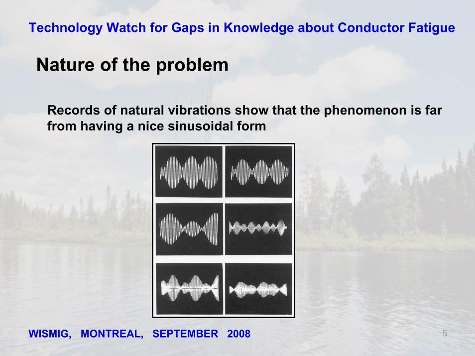
Nature of the problem
Records of natural vibrations show that the phenomenon is farfrom having a nice sinusoidal form
6WISMIG, MONTREAL, SEPTEMBER 2008
Technology Watch for Gaps in Knowledge about Conductor Fatigue
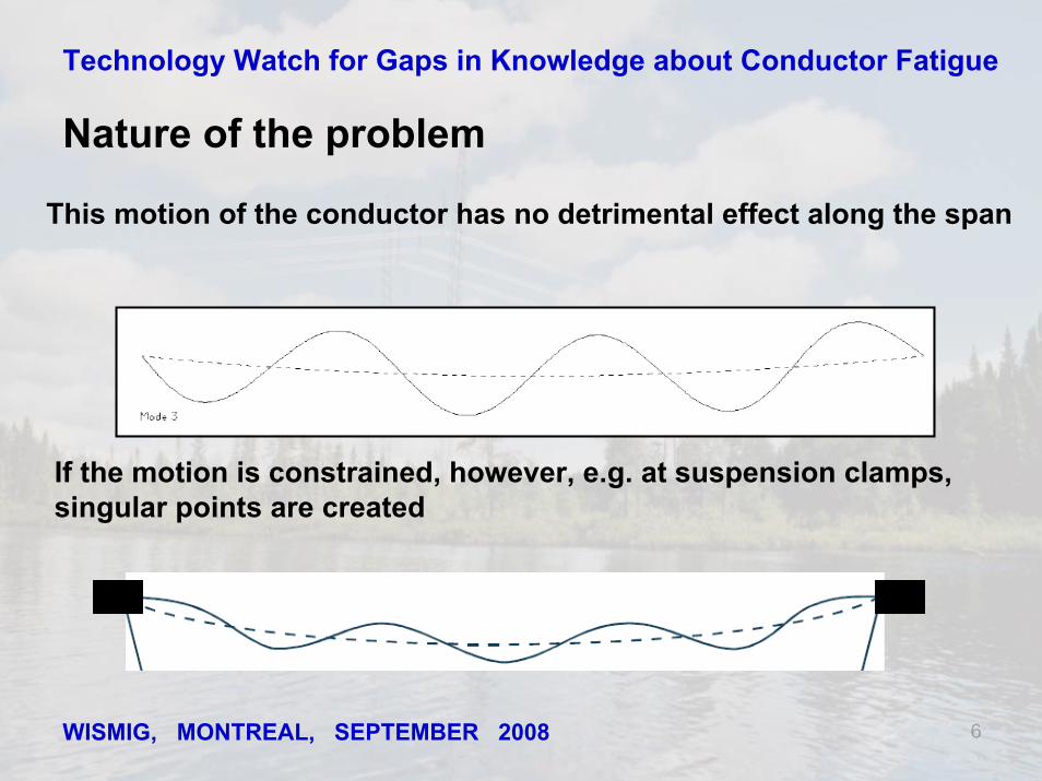
This motion of the conductor has no detrimental effect along the span
Nature of the problem
If the motion is constrained, however, e.g. at suspension clamps,singular points are created

7WISMIG, MONTREAL, SEPTEMBER 2008
Technology Watch for Gaps in Knowledge about Conductor Fatigue
Nature of the problem
At such a location, conductor curvatures are much larger than in the free span. Interstrandmicroslip amplitude increases, small cracks are generated and some propagate up to complete strand failures caused by fretting fatigue.
To a lesser extent, a similar phenomenon can occur at damper, marker or spacer clamps.

8WISMIG, MONTREAL, SEPTEMBER 2008
Technology Watch for Gaps in Knowledge about Conductor Fatigue
Conductor/clamp systems
Conductor designs are not unique, their fatigueperformance depends on their configurationConductor fatigue most often occurs at suspension clamps. Different conductor supports are availablebut a complete study of the impact of their design on the fatigue performance of a conductor has yet tobe completed.

9WISMIG, MONTREAL, SEPTEMBER 2008
Technology Watch for Gaps in Knowledge about Conductor Fatigue
CONDUCTORS
• An important component of an overhead power line, it contributesto up to 40% of total capital investment.
• Much attention is given to the selection of a conductor configuration to meet load requirements.
• It thus take different configurations to best meet those requirements.
• Most common types of bare overhead conductors are constructedfrom commercially pure aluminium e.g. AAC
• For added strength, different alloys are used e.g. AAAC
• For a better strength-to-weight ratio, a strenght member such as steelwires may be added in the core e.g. ACSR
Conductor/clamp systems

10WISMIG, MONTREAL, SEPTEMBER 2008
Technology Watch for Gaps in Knowledge about Conductor Fatigue
Conductor/clamp systems
TYPICAL CONFIGURATION OF A BARE CONDUCTOR
• Layers of round wires are stranded first around a so-called core• The stranding takes place in alternating directions from layer to layer• For conductors with equal diameter wires, each lay has six wiresmore than the previous to assure a good fit• To tailor the conductor for various strenght-to-weight ratios, unequal diameter wires are often used.

11WISMIG, MONTREAL, SEPTEMBER 2008
Technology Watch for Gaps in Knowledge about Conductor Fatigue
Conductor/clamp systemsSOME SPECIAL CONDUCTORS
Trapezoidal, Z-shaped compact, Self-damping, Expanded and River crossing conductors:

12WISMIG, MONTREAL, SEPTEMBER 2008
Technology Watch for Gaps in Knowledge about Conductor Fatigue
CLAMPING SYSTEMS (1)
Different designs of suspension clamps
Conductor/clamp systems

13WISMIG, MONTREAL, SEPTEMBER 2008
Technology Watch for Gaps in Knowledge about Conductor Fatigue
CLAMPING SYSTEMS (2)
•Newer design with elastomeric insert
•Special river crossing clamp
Conductor/clamp systems

14WISMIG, MONTREAL, SEPTEMBER 2008
Technology Watch for Gaps in Knowledge about Conductor Fatigue
CLAMPING SYSTEMS (3)
Some characteristics of the design:
• The profile of the body should theoretically follow the naturalcurvature of the conductor• In practice an optimum profile design is found taking into accountthe different load assumptions• The main profile of the body (and keeper) must be rounded and curved into a bell mouth to avoid damaging the conductor in case of exceptional overloads• The clamp should be able to rotate in a longitudinal vertical plane to accomodate asymmetrical loads• The rotation is assured by a pivot either below, above or at the conductor axis
Conductor/clamp systems

15WISMIG, MONTREAL, SEPTEMBER 2008
Technology Watch for Gaps in Knowledge about Conductor Fatigue
FATIGUE ENDURANCE OF CONDUCTOR/CLAMP SYSTEMS
• Fatigue of conductors is due to microslip movements of wiresinducing fretting fatigue• The phenomenon is complex and its exact modelling has yet to becompleted• The knowledge on fatigue performance of conductors mostly relies on results of laboratory tests made on conductors in fixed short metallic clamps• The determination of the fatigue endurance of a conductor alone isnot possible with the present knowledge of the phenomenon• The above review of conductors and supports illustrated theirdiversity of design and geometry• The direct extrapolation of fatigue data available to other types of conductors or to different types of supports is not recommended
Conductor/clamp systems

16WISMIG, MONTREAL, SEPTEMBER 2008
Technology Watch for Gaps in Knowledge about Conductor Fatigue
ENGINEERING DESIGN TOOLS
Aeolian vibration amplitudes and fatigue of conductors
•After more than 80 years of active work, the complexity of bothphenomena did not permit to propose complete solutions supported by thorough analysis taking into account the numerous parameters varyingboth in space and time
•Engineering solutions were sought concurrently. Through the years theybecame reliable design tools
•When applied correctly, within the limits inherent to their definitions, they permit to assure an acceptable control of the situation pending the completion of more complete analytical tools

17WISMIG, MONTREAL, SEPTEMBER 2008
Technology Watch for Gaps in Knowledge about Conductor Fatigue
WISMIG, MONTREAL, SEPTEMBER 2008
Technology Watch for Gaps in Knowledge about Conductor Fatigue
Aeolian vibration amplitudes and fatigue of conductors
• Both aspects were studied concurrently
• Emphasis was first put on the elimination conductor vibrations
• Hence fatigue was often retained as one of the parameters
• Two examples of such engineering design tools:
- Modelling for prediction of maximum antinode amplitudes
- Overhead conductor safe design tension
• Both approaches make use of the Energy Balance Principle (EBP)

18WISMIG, MONTREAL, SEPTEMBER 2008
Technology Watch for Gaps in Knowledge about Conductor Fatigue
Aeolian vibration amplitudes and fatigue of conductors
Modelling for prediction of maximum antinode amplitudes Damper Dimensions &
Material Properties
Conductor Mass & Stiffness
Tension
Damper Spacing
Conductor Self-Damping
Wind Power
Turbulence Effects
Locale Span Length
Conductor FatigueCharacteristic
Equationsof Motion
DamperImpedance
Impedance MatchingAnalysis
Damping Efficiency on Conductor
PowerBalanceAnalysis
VibrationAmplitude
FatigueDamageModel
Incidence of Conductor Fatigue
Shaker Test
Lab Span Test
FieldRecordings
Inspection of Line
Outline of the technologyapplied to the case of a single conductor plus damper making use of the Energy Balance Principle (EBP)
CIGRE TF B2.11.01ELECTRA # 223 DEC. 2005
(Fatigue)
(EBP)

19WISMIG, MONTREAL, SEPTEMBER 2008
Technology Watch for Gaps in Knowledge about Conductor Fatigue
Energy Balance Principle (EPB)
Aeolian vibration amplitudes and fatigue of conductors
• The EBP works in the frequency domain, one mode of vibration at a time
• The steady state solutions computed correspond to the maximum amplitude which could be excited on a conductor at that frequency
• Transient effects (e.g. wind turbulence ) cannot be taken into account
• Energy input is evaluated in a condition of laminar wind
• Conductor self-damping is the sole energy dissipator in the simplest case
• The presence of damper(s) requires an adequate modelling of itsinteraction with the conductor

20WISMIG, MONTREAL, SEPTEMBER 2008
Technology Watch for Gaps in Knowledge about Conductor Fatigue
PREDICTION OF MAXIMUM ANTINODE AMPLITUDES
• The Energy Balance Principle (EBP) is an analytical approach that can beusefully used to investigate alternatives in the design or redesign process
• Being aware of its limits, the EBP can also be used for the direct design of the damping system for a new line
• EBP permits to determine an estimate of an upper bound to the expectedvibratory motions
• The acceptable upper bound value entirely depends on the choice of a fatigue parameter for the conductor/clamp system under evaluation
• The straightforward EBP is considered acceptable for use for engineering applications
Aeolian vibration amplitudes and fatigue of conductors

21WISMIG, MONTREAL, SEPTEMBER 2008
Technology Watch for Gaps in Knowledge about Conductor Fatigue
Limitations regarding the EBP for prediction of maximum antinode amplitudes of vibrationref: Conclusion of paper « Modelling of aeolian vibrations of a single conductor plus damper: assessment of technology »,
CIGRE TF B2.11.01, Electra, No 223, December 2005 pp.28-36
« The strains predicted by the different researchers exhibitconsiderable variability. Nevertheless analytical methods based on the EBP and shaker-based technology can provide a useful tool for use in design of damping systems for the protection of single conductors against aeolian vibrations. It should be used withcircumspection and be supplemented by references to fieldexperience. Greater accuracy can be obtained by evaluating damper dissipation on laboratory span rather than on the shaker. »
Aeolian vibration amplitudes and fatigue of conductors

22WISMIG, MONTREAL, SEPTEMBER 2008
Technology Watch for Gaps in Knowledge about Conductor Fatigue
Aeolian vibration amplitudes and fatigue of conductors
• Approaches to guide an assessment of the severity of vibrations can bepragmatic, through design rules based on passed experience
• Conditions can also be assessed through measurements on existing lines
• The mechanical tension of the conductors was reckoned at the early stage as an important parameter related to the presence of conductor vibrations
• Recently, CIGRE TF B2.11.04 proposed an engineering design tool: « Overhead conductor safe design tension with respect to aeolian vibrations »CIGRE TB # 273 June 2005
OVERHEAD CONDUCTOR SAFE DESIGN TENSION

23WISMIG, MONTREAL, SEPTEMBER 2008
Technology Watch for Gaps in Knowledge about Conductor Fatigue
Aeolian vibration amplitudes and fatigue of conductorsOVERHEAD CONDUCTOR SAFE DESIGN TENSION
Effective wind recurrence
Conductor tension design guide - modelling approach
Tension
Clamping systemConductor typeConductor strandingConductor condition
Span lengthConductor size
Effective wind turbulenceWind statisticsTerrain category
Wind power input
Energy balance
Increase ordecrease tension
Resp. : Tol.= O.K. , limiting design value
ResponseIntensityRecurence
Tolerance to vibrations
Damping capacity
STRUCTURAL SYSTEM
EXCITATION
< >
(Fatigue)
(EBP)

24
WISMIG, MONTREAL, SEPTEMBER 2008
Technology Watch for Gaps in Knowledge about Conductor Fatigue
Aeolian vibration amplitudes and fatigue of conductors
OVERHEAD CONDUCTOR SAFE DESIGN TENSIONBasic assumptions underlaying model calculations
Organisation IREQ / Leblond & Hardy [25] Alcoa Fujikura / Rawlins [26]Approach Endurance Limit Endurance Limit Conductor damping capacity
Calculated on the basis of similarity laws calibrated by means of
measured data (ISWR method).
Measured (ISWR method)
Span-end damping Travelling wave approach using complex damper stiffness measured
on shaker
Measured efficiency of span-end damping arrangement
Wind power input Laminar or reduced for normally-distributed turbulence
Laminar or reduced for turbulence
Vibration mode shape
Narrow band random vibration (peak amplitudes Rayleigh-
distributed, maximum amplitude limited to 3.5 times RMS-value at
each frequency)
Sinusoidal
Conductor tolerance to vibration
Fatigue endurance as per [13] Fatigue endurance as per [13]
Clamping system Fixed metal to metal clamps Fixed metal to metal clamps
(13) Chapter 2 of « Wind induced Conductor motion » EPRI Transmission Line Reference Book,1979
(Fatigue)

25WISMIG, MONTREAL, SEPTEMBER 2008
Technology Watch for Gaps in Knowledge about Conductor Fatigue
Aeolian vibration amplitudes and fatigue of conductors
OVERHEAD CONDUCTOR SAFE DESIGN TENSION

26WISMIG, MONTREAL, SEPTEMBER 2008
Technology Watch for Gaps in Knowledge about Conductor Fatigue
Aeolian vibration amplitudes and fatigue of conductorsOVERHEAD CONDUCTOR SAFE DESIGN TENSION
• The CIGRE guide for conductor safe design tension with respect to aeolian vibrations is based on calculations making use of the EBP
• The limitations expressed previously for the use of EPB to evaluate the maximum antinode amplitudes of vibration are thus also inherent in thisengineering design tool
• Cases calculated to draw the safe zones are based on conservativeconditions of conductors supported in fixed short metallic clamps

27WISMIG, MONTREAL, SEPTEMBER 2008
Technology Watch for Gaps in Knowledge about Conductor Fatigue
•The conductor/clamp system is represented as a cantilever beam in bending• The bending amplitude Yb is defined at 89 mm from LPC
• Bending amplitude method is valid only for conductors fitted with solid metallic clamps whereLPC can be reached (armored orunarmored)
•Cushioned clamps (armored or unarmored) need special treatment. Xb=89mm
Yb
b boraσ or aε
Bending model of the conductor /clamp system
LPC
Plane of

28WISMIG, MONTREAL, SEPTEMBER 2008
Technology Watch for Gaps in Knowledge about Conductor Fatigue
An idealized bending stress (Poffenberger-Swart formula) is calculated at the outer-layer strand in the plane of the last point of contact (LPC) as function of Yb
Ea: modulus of elasticity of outer wire material (N/mm2)d: diameter of outer- layer wire (mm)p = (H/EI)½H: conductor tension at average temperature during test period (N)EI: sum of flexural rigidities of individual wires in the cable (N mm2)x: distance from the point of measurement to the last point of contact
( ) bpxa
a Ypxe
pdE+−
= − 14
2σ
Simplified Analytical Representation of the Fatigue Phenomenon (1)

29WISMIG, MONTREAL, SEPTEMBER 2008
Technology Watch for Gaps in Knowledge about Conductor FatigueSimplified Analytical Representation of the Fatigue Phenomenon (2)
The antinode amplitude of vibration, ymax, is also a useful parameter
The stress formula becomes:
Ea: Young’s modulus for the outer-layer strand material (N/mm2)d: diameter of outer- layer wire (mm)f: frequency of the motion (Hz)m: conductor mass per unit length (kg/m)EI: sum of flexural rigidities of individual wires in the cable (N mm2)
maxaa fyEImEdπσ =
30WISMIG, MONTREAL, SEPTEMBER 2008
Technology Watch for Gaps in Knowledge about Conductor Fatigue
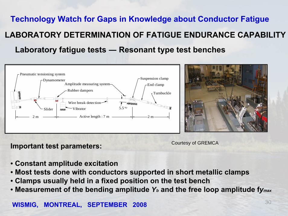
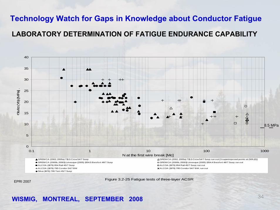
LABORATORY DETERMINATION OF FATIGUE ENDURANCE CAPABILITY
Laboratory fatigue tests ― Resonant type test benches
Pneumatic tensioning system
Slider
DynamometerAmplitude measuring system
Rubber dampers
Wire break detectionVibrator
Active length : 7 m2 m 2 m
Suspension clamp
End clamp
Turnbuckle
5.5
Important test parameters:
• Constant amplitude excitation• Most tests done with conductors supported in short metallic clamps• Clamps usually held in a fixed position on the test bench• Measurement of the bending amplitude Yb and the free loop amplitude fymax
Courtesy of GREMCA

31WISMIG, MONTREAL, SEPTEMBER 2008
Technology Watch for Gaps in Knowledge about Conductor Fatigue
LABORATORY DETERMINATION OF FATIGUE ENDURANCE CAPABILITY
Characterization of the fatigue behaviour of a conductor
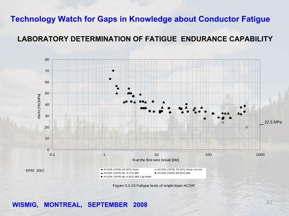
• The results of such tests ultimately lead to the presentation of a fatigue (S-N) curve •Idealized bending stress at conductor surface vs megacycles to failure•The endurance limit is determined at 500 megacycles•Stress expressed as function of Yb or fymax,
Endurance limits:stress as function of Yb:22.5 MPa for single-layer ACSR 8.5 MPa for multi-layer ACSRstress as function of fymax:22 MPa for ACSR
EPRI 1979
f(Yb)
32WISMIG, MONTREAL, SEPTEMBER 2008
Technology Watch for Gaps in Knowledge about Conductor Fatigue
Figure 3.2-23 Fatigue tests of single-layer ACSR.
0
10
20
30
40
50
60
70
80
0.1 1 10 100 1000N at the first wire break [Mc]
σ a fc
t (Y
b) [M
Pa]
ALCOA (1979) 1/0 (6/1) Susp ALCOA (1979) 1/0 (6/1) Susp; run outALCOA (1979) No. 4 (7/1) BM ALCOA (1979) 3/0 (6/1) BMALCOA (1979) No. 4 (6/1) BM; Log mean
LABORATORY DETERMINATION OF FATIGUE ENDURANCE CAPABILITY
EPRI 2007
_ 22.5 MPa

33WISMIG, MONTREAL, SEPTEMBER 2008
Technology Watch for Gaps in Knowledge about Conductor Fatigue
Figure 3.2-24 Fatigue tests of two-layer ACSR
0
5
10
15
20
25
30
35
40
45
0.1 1 10 100 1000
N at the first wire break [Mc]
σ a fc
t (Yb)
[MPa]
EPRI (1987) 795 Drake 26/7 Susp EPRI (1987) 795 Drake Susp; run outALCOA (1979) 397.5 Lark 30/7 Susp ALCOA (1979) 397.5 Lark Susp; run outGREMCA (2006a, 2001) Dalpé (1999) 795 Drake 26/7 Susp GREMCA (2006a, 2001) Dalpé (1999) 795 Drake Susp; run out [2 superimposed points at (500,19)]ALCOA (1979) 397.5 Lark 30/7 BM
LABORATORY DETERMINATION OF FATIGUE ENDURANCE CAPABILITY
EPRI 2007
34WISMIG, MONTREAL, SEPTEMBER 2008
Technology Watch for Gaps in Knowledge about Conductor Fatigue
LABORATORY DETERMINATION OF FATIGUE ENDURANCE CAPABILITY
Figure 3.2-25 Fatigue tests of three-layer ACSR
0
5
10
15
20
25
30
35
40
0.1 1 10 100 1000N at the first wire break [Mc]
σ a fc
t (Yb)
[MPa] .
GREMCA (2002, 2005a) 715.5 Crow 54/7 Susp GREMCA (2002, 2005a) 715.5 Crow 54/7 Susp; run out [3 superimposed points at (500,12)]
GREMCA (2000b, 20001) Lévesque (2005) 1354.5 Bersfort 48/7 Susp GREMCA (2000b, 20001) Lévesque (2005) 1354.4 Bersfort 48/7 Susp; run outALCOA (1979) 954 Rail 45/7 Susp ALCOA (1979) 954 Rail 45/7 Susp; run out
ALCOA (1979) 795 Condor 54/7 BM ALCOA (1979) 795 Condor 54/7 BM; run outSilva (1976) 795 Tern 45/7 Susp
EPRI 2007
__8.5 MPa

35WISMIG, MONTREAL, SEPTEMBER 2008
Technology Watch for Gaps in Knowledge about Conductor Fatigue
Figure 3.2-13a Fatigue tests of two-layer ACSR
0
10
20
30
40
50
60
70
0.1 1 10 100 1000N at the first wire break [Mc]
σa fc
t (fy
max
) [M
Pa]
Seppä (1969) 397.5 Ibis 26/7 Susp EPRI (1987) 795 Drake 26/7 SuspEPRI (1987) 795 Drake 26/7 Susp; run out GREMCA (2006a, 2001) Dalpé (1999) 795 Drake 26/7 SuspGREMCA (2006a, 2001) Dalpé (1999) 795 Drake 26/7 Susp; run out ALCOA (1979) 397.5 Lark 30/7 SuspALCOA (1979) 397.5 Lark Susp; run out ALCOA (1979) 397.5 Lark 30/7 BM
EPRI 2007

36WISMIG, MONTREAL, SEPTEMBER 2008
Technology Watch for Gaps in Knowledge about Conductor Fatigue
Figure 3.2-13b Fatigue tests of three-layer ACSR
0
10
20
30
40
50
60
70
0.1 1 10 100 1000N at the first wire break [Mc]
σa fc
t (fy
max
) [M
Pa]
GREMCA (2002, 2005a) 715.5 Crow Susp ALCOA (1979) 954 Rail 45/7 Susp
GREMCA (2002,2005a) 715.5 Crow 54/7 Susp; run out [2 superimposed points at (500,24)] ALCOA (1979) 954 Rail 45/7 Susp; run outGREMCA (2000b, 2001) Lévesque (2005) 1354.5 Bersfort 48/7 Susp; run out ALCOA (1979) 795 Condor 54/7 BM
GREMCA (2000b, 2001) Lévesque (2005) 1354.5 Bersfort 48/7 Susp ALCOA (1979) 795 Condor 54/7 BM; run outSilva (1976) 795 Tern 45/7 Susp
LABORATORY DETERMINATION OF FATIGUE ENDURANCE CAPABILITY
EPRI 2007
_22 MPa

37WISMIG, MONTREAL, SEPTEMBER 2008
Technology Watch for Gaps in Knowledge about Conductor Fatigue
LABORATORY DETERMINATION OF FATIGUE ENDURANCE CAPABILITY
Conversion of fymax to Yb endurance limits
Ratio Yb/fymax should be obtained experimentally for given axial load and conductor/clamp system. The values of stresses at the outer layer strand are different surrogates for the actual fatigue–initiating stress at the strand contacts where failures originate.
Endurance limits that have been established in terms of fymax may beconverted to Yb endurance limits by experimental determination in a laboratoryspan of the value of Yb that corresponds to the fymax endurance limit. This should be done at the fymax endurance limit. Yb does not always vary linearlywith fymax.

38WISMIG, MONTREAL, SEPTEMBER 2008
Technology Watch for Gaps in Knowledge about Conductor Fatigue
Statistical representation of twoSS--N N curvescurves::
• Average (50 %)
• 95% probability of survival
LABORATORY DETERMINATION OF FATIGUE ENDURANCE CAPABILITY
1 10 100 1000N = Megacycles to failure
0
10
20
30
40
Pof
fenb
erge
r-Sw
art s
tress
rela
tive
to Y
b (M
Pa)
Average S-N curve (50%)95% probability of survival curve

39WISMIG, MONTREAL, SEPTEMBER 2008
Technology Watch for Gaps in Knowledge about Conductor Fatigue
Estimated bendingamplitude endurance limits for ACSR
LABORATORY DETERMINATION OF FATIGUE ENDURANCE CAPABILITY
EPRI 1979

40WISMIG, MONTREAL, SEPTEMBER 2008
Technology Watch for Gaps in Knowledge about Conductor Fatigue
Bending Amplitude Recorders
In-situ measurement of conductor vibation
Vibrec 400 Pavica

41WISMIG, MONTREAL, SEPTEMBER 2008
Technology Watch for Gaps in Knowledge about Conductor Fatigue
Spectrum loading and cumulative damage
• When S/N curves are available, it is possible to determine an endurance limit applicable to the cases studied.
• The systematic use of the endurance limit as the maximum value of bending amplitude acceptable represents a safe design choice, but could imply an unnecessary margin of overdesign.
• To go from the constant to the variable amplitude situation, the usualapproach is to use a cumulative damage law .
• Miner’s rule is widely used because of its simplicity despite the following two limitations:
It is independent of the cycle sequence.
Stress levels below the endurance limit are ignored.

42WISMIG, MONTREAL, SEPTEMBER 2008
Technology Watch for Gaps in Knowledge about Conductor Fatigue
Usually based on cumulative damage theory (Miner’s rule) withthe following hypotheses:
Total damage D at several stress levels σi cumulates linearly:
D= Σ ni/NiFailure is predicted when:
D = Σ ni/Ni =1
Note: the use of D=1 has not been confirmed experimentally for conductors.
Constant Amplitude Data and Variable Amplitudes Vibrations
Spectrum loading and cumulative damage

43WISMIG, MONTREAL, SEPTEMBER 2008
Technology Watch for Gaps in Knowledge about Conductor Fatigue
GAPS TO BE FILLED (1)Two of the engineering design tools available are aimed at limiting the
amplitudes of vibration1. Model to predict acceptable antinode vibration amplitudes2. Model to evaluate tension to avoid detrimental vibrations
Both approaches are based on some empirical knowledge or somesimplified models.e.g. both use EBP where wind input, conductor self damping, damper characteristics and damper/conductor interaction are complex situations that are difficult to model accurately.In both cases, the limit for the calculations is a criterion related tothe fatigue of conductors. For the moment, the only reliable criterion for conductor fatigue isthe bending amplitude method applied to the case of a conductorsupported in a short metallic clamp.It severely limits their application to cases with different supports.

44WISMIG, MONTREAL, SEPTEMBER 2008
Technology Watch for Gaps in Knowledge about Conductor Fatigue
GAPS TO BE FILLED (2)
Although the present conductor fatigue criterion, related to bendingamplitudes, presents severe limitations it has been a useful tool until nowbecause of the frequent choice of short metallic supension clamps to support a conductor.The laboratory fatigue results available when the first EPRI Orange Book was published (1979) was limited to cases with short support clamps. It did not permit to consider the influence of the clamp geometry as an important parameter.More recent work rather lead towards the consideration of the clampdesign as an important parameter for the fatigue performance of the conductor.• Incorporated elastomeric inserts, are good examples.• The clamp design (geometry) should be part of the study.
Influence of clamp design

45WISMIG, MONTREAL, SEPTEMBER 2008
Technology Watch for Gaps in Knowledge about Conductor Fatigue
GAPS TO BE FILLED (3)
Conductor configuration
The results of laboratory fatigue tests that were made until now mostlyrefer to ACSR conductors supported in a short metallic clamp.It is important to conduct similar tests on conductor of differentconfigurations and to take advantage of the present data available to assess the importance of the strand geometry, size and material, the importance of the choice of the number of layers on the fatigue endurance of the conductor.
Armour rods
With the advantage of measuring Yb and fymax in a fatigue test, the influence of the presence of armour rods could be evaluated.Armour rods , for a given fymax, will affect the value of Yb at the clamp.(They could also reduce fymax at given wind conditions)

46WISMIG, MONTREAL, SEPTEMBER 2008
Technology Watch for Gaps in Knowledge about Conductor Fatigue
GAPS TO BE FILLED (4)
Spectrum loading and cumulative damage
Laboratory tests at variable amplitudes are necessary to determine an appropriate cumulative law and to indicate its limits. e.g. Miner’s Law
N.b.. Amplitudes of conductor vibrations are not constant values and design with endurance limits is a very conservative when the S/N curve isknown.
Fatigue tests with large amplitudes
The occurrence of galop on the lines indicated that in some occasion that phenomenon may have been the cause of strand failures.Tests at large amplitudes are necessary to identify the nature of the strand failures.

47WISMIG, MONTREAL, SEPTEMBER 2008
Technology Watch for Gaps in Knowledge about Conductor Fatigue
GAPS TO BE FILLED (5)
In situ measurements
• Instruments to detect strand failures
• Instruments (in span) to measure antinode amplitudes(present recorders measure a curvature parameter at the clamps)

48
Technology Watch for Gaps in Knowledge about Conductor Fatigue
GAPS TO BE FILLED (6)
Limitations to present methods for the characterization of fatigue performance
• Dispersion of fatigue results, use of statistical approach
• Detection of broken strands, relation between first and subsequent breaks
• Criteria for test termination
• Modification to laboratory test bench to better evaluate special supports
WISMIG, MONTREAL, SEPTEMBER 2008

49WISMIG, MONTREAL, SEPTEMBER 2008
Technology Watch for Gaps in Knowledge about Conductor Fatigue
GAPS TO BE FILLED (7)
•Definition of an adequate model related to the cause of the strand failures: fretting fatigue.
- contact mechanics for the analysis of crack initiation
- fracture mechanics for the analysis of crack propagation
Note: It is of paramount importance that such work takes into account the knowledge already available through studies related to the simplified flexion model, in order to keep making good use of the data bank presently developed.

50WISMIG, MONTREAL, SEPTEMBER 2008
Technology Watch for Gaps in Knowledge about Conductor Fatigue
PROPOSAL FOR A RESEARCH PLANWith reference to actual bending model
Laboratory tests, constant amplitudes:• Conductor configuration: strand geometry, size, material,
and # of layers.• Presence of armored rods• Influence of clamp design:
elastomeric inserts (continuous or at the ends), inserts and armored rods (AGS)geometry of metallic clamps (length, curvature)
• Large amplitudes (conditions of galop)
Laboratory tests, spectrum loading (for evaluation of cumulative damage laws)
Note: Labo tests are the 1st avenue to explore before trying to definelinks to the flexion model

51WISMIG, MONTREAL, SEPTEMBER 2008
Technology Watch for Gaps in Knowledge about Conductor Fatigue
PROPOSAL FOR A RESEARCH PLAN
2. Other aspects related to laboratory tests
• Detection of strand failures, relationship between first and subsequent
• Dispersion of results, statistical approach• Criteria for test termination• Modification to test bench to accomodate special supports
e.g. symmetric excitation
3. In situ measurements
• Instrument to detect strand failure(s)• In span instrument to measure antinode amplitudes
( present recorders measure a curvature parameter at clamps)

52WISMIG, MONTREAL, SEPTEMBER 2008
Technology Watch for Gaps in Knowledge about Conductor Fatigue
PROPOSAL FOR A RESEARCH PLAN
4. More fundamental work
Definition of a new fatigue criterion (index) related to fretting(still related to Yb via interstrand micro slip)
The avenues for such a modelisation are:
• contact mechanics, to identify conditions of micro cracks initiation
• fracture mechanics, to define conditions of cracks propagation

53WISMIG, MONTREAL, SEPTEMBER 2008
Technology Watch for Gaps in Knowledge about Conductor Fatigue
DISCUSSION