ga2xxxxnvc-bxxxx - home - fireboy-xintexclean agent novec 1230 ga2xxxxnvc-bxxxx sizes: 1200-4000 cu....
TRANSCRIPT
1 Part Number 18022, Revision A, 04/15/2015
CG2 & MA2 Series
Clean Agent Novec 1230
GA2XXXXNVC-BXXXX Sizes: 1200-4000 cu. ft.
Owner’s Manual &
Installation Instructions
Project ID: 0003053255
U.S. Coast Guard Approved
No. 162.029/254/0
Read and comply with all instructions, warnings and limitations before installing, servicing or removing this device.

2 Part Number 18022, Revision A, 04/15/2015
Additional copies this of manual are available at no charge by contacting the manufacturer, distributor or dealer. Fireboy-Xintex reserves the right to change features without notice.
General Information 3
Specifications 4
Operation of Fireboy Fire Extinguisher 6
Marine Installation Instructions 7
Before Installation 7
Selecting a Location 7
Mounting Fireboy System 9
Installing Discharge Piping 10
Installing Discharge Piping Supports 12
Installing Temperature Sensors 12
Installing GA-Link Hose 13
Cable Installation (P/N: E-4209-XXX, XXX= Length in Feet) 15
Routing the Cable 15
Escutcheon Plate and T-Handle 16
Connecting Cable to Cylinder 18
Arming GA System 21
Accommodating Diesel Engines 22
Installing Indicator Lamp (P/N: 90107) 22
Mounting Indicator Lamp 22
Wiring Indicator Lamp 23
Connecting to Powered Ventilation 24
Installation Checklist 25
Maintaining Fireboy Fire Extinguisher 26
Maintaining the Indicator Lamp Circuit 28
Additional Equipment 28
Health and Safety 29
MSDS 31
Returning Fireboy-Xintex Equipment 39
Recharging Fireboy Extinguishers 39
Warranty 40
3 Part Number 18022, Revision A, 04/15/2015
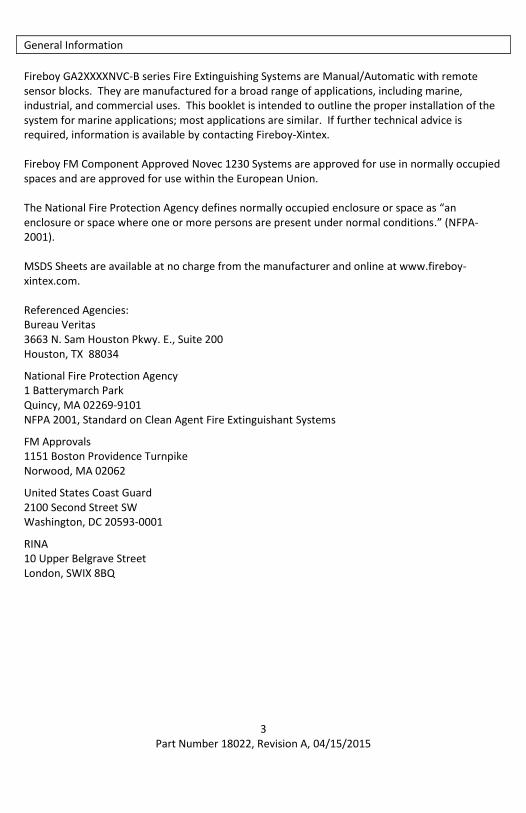
General Information
Fireboy GA2XXXXNVC-B series Fire Extinguishing Systems are Manual/Automatic with remote sensor blocks. They are manufactured for a broad range of applications, including marine, industrial, and commercial uses. This booklet is intended to outline the proper installation of the system for marine applications; most applications are similar. If further technical advice is required, information is available by contacting Fireboy-Xintex. Fireboy FM Component Approved Novec 1230 Systems are approved for use in normally occupied spaces and are approved for use within the European Union. The National Fire Protection Agency defines normally occupied enclosure or space as “an enclosure or space where one or more persons are present under normal conditions.” (NFPA-2001). MSDS Sheets are available at no charge from the manufacturer and online at www.fireboy-xintex.com. Referenced Agencies: Bureau Veritas 3663 N. Sam Houston Pkwy. E., Suite 200 Houston, TX 88034 National Fire Protection Agency 1 Batterymarch Park Quincy, MA 02269-9101 NFPA 2001, Standard on Clean Agent Fire Extinguishant Systems FM Approvals 1151 Boston Providence Turnpike Norwood, MA 02062 United States Coast Guard 2100 Second Street SW Washington, DC 20593-0001 RINA 10 Upper Belgrave Street London, SWIX 8BQ

4 Part Number 18022, Revision A, 04/15/2015
General Information Continued
WARNING:
1. NEVER INSTALL A FIREBOY SYSTEM ON THE UNDERSIDE OF A HATCH COVER OR ON AN ACCESS DOOR THAT MAY OPEN OR SEPARATE IN AN EXPLOSION
2. NEVER INSTALL THE ACTUATOR OR SENSOR BLOCK OF A FIREBOY SYSTEM IN CLOSE PROXIMITY TO EXHAUST MANIFOLDS OR TURBOCHARGERS. RADIATED HEAT MAY CAUSE PREMATURE ACTUATION
3. NEVER INSTALL A FIREBOY GA CYLINDER HORIZONTALLY OR UPSIDE DOWN 4. NEVER INSTALL A FIREBOY SYSTEM WHERE IT WILL TRAP OR BE IN DIRECT CONTACT
WITH WATER 5. NEVER INSTALL A FIREBOY UNIT IN A COMPARTMENT LARGER THAN ITS VOLUME
RATING 6. NEVER COMBINE THE VOLUME RATING OF TWO OR MORE FIREBOY UNITS TO PROTECT
A GIVEN COMPARTMENT 7. THIS DEVICE SHALL NOT BE INSTALLED OR USED IN AIRCRAFT AND/OR RACING VEHICLES 8. DIESEL POWERED CRAFT MUST ALSO INSTALL THE AUTOMATIC ENGINE SHUTDOWN
SYSTEM OR THIS SYSTEM MAY NOT EXTINGUISH THE FIRE (SEE ADDITIONAL EQUIPMENT)
9. FIREBOY SYSTEMS ARE NOT, NOR ARE THEY INTENDED TO BE, EXPLOSION SUPPRESSION DEVICES. THEY DO NOT LESSEN THE NEED TO INSPECT FOR FIRE HAZARDS AND TO VENTILATE ANY AREA WHERE FLAMMABLE FUMES MAY ACCUMULATE.
10. IN CASE OF ACCIDENTAL DISCHARGE, EVACUATE PROTECTED SPACE AND VENTILATE. DO NOT RETURN TO AREA UNTIL SPACE IS CLEAR OF AGENT. REFER TO HEALTH AND SAFETY SECTION (PAGE 29).
NOTE:
TO DETERMINE SYSTEM SPECIFICATIONS, REFER TO FACTORY PROVIDED WORKSHEETS.
Specifications
GA2XXXXNVC-B series extinguishers discharge automatically at a temperature of 175°F (79° C) or may be discharged manually at any temperature. All models introduce an atmospheric concentration of 5.85% into the protected space. This concentration includes a 30% safety factor to the 4.5% Minimum Extinguishing Concentration (MEC). Operational temperature range of extinguishers is 32°F (0°C) to 130°F (54°C).

5 Part Number 18022, Revision A, 04/15/2015
Volume
Protected Diameter Total Height
Agent Weight
Per Cylinder
Shipping Weight
Per Cylinder
System Pressure (@70° F)
Model Number ft^3 m^3 in mm in mm lbs kgs lbs kgs psi
GA21200NVC-BXXXX 1200 34.0 10 254 27.1 689 32.2 14.6 70 31.8 360 GA21300NVC-BXXXX 1300 36.8 10 254 27.1 689 34.9 15.8 73 33.1 360 GA21400NVC-BXXXX 1400 39.6 10 254 27.1 689 37.6 17.1 76 34.5 360 GA21500NVC -BXXXX 1500 42.5 10 254 27.1 689 40.3 18.3 78 35.4 360 GA21600NVC-BXXXX 1600 45.3 10 254 27.1 689 43.0 19.5 81 36.7 360 GA21700NVC-BXXXX 1700 48.1 10 254 27.1 689 45.7 20.7 84 38.1 360 GA21800NVC-BXXXX 1800 51.0 10 254 33.3 846 48.4 22.0 91 41.3 360 GA21900NVC-BXXXX 1900 53.8 10 254 33.3 846 51.0 23.1 94 42.6 360 GA22000NVC-BXXXX 2000 56.6 10 254 33.3 846 53.7 24.4 97 44.0 360 GA22100NVC-BXXXX 2100 59.5 10 254 33.3 846 56.4 25.6 99 44.9 360 GA22200NVC-BXXXX 2200 62.3 10 254 33.3 846 59.1 26.8 102 46.3 360 GA22300NVC-BXXXX 2300 65.1 10 254 33.3 846 61.8 28.0 105 47.6 360 GA22400NVC-BXXXX 2400 68.0 10 254 33.3 846 64.5 29.3 108 49.0 360 GA22500NVC-BXXXX 2500 70.8 10 254 38.1 968 67.2 30.5 117 53.1 360 GA22600NVC-BXXXX 2600 73.6 10 254 38.1 968 69.8 31.7 120 54.4 360 GA22700NVC-BXXXX 2700 76.5 10 254 38.1 968 72.5 32.9 123 55.8 360 GA22800NVC-BXXXX 2800 79.3 10 254 38.1 968 75.2 34.1 125 56.7 360 GA22900NVC-BXXXX 2900 82.0 10 254 38.1 968 77.9 35.3 128 58.1 360 GA23000NVC-BXXXX 3000 85.0 10 254 38.1 968 80.6 36.6 131 59.4 360 GA23100NVC-BXXXX 3100 87.8 10 254 47.3 1202 83.3 37.8 141 64.0 360
GA23200NVC-BXXXX 3200 90.6 10 254 47.3 1202 86.0 39.0 144 65.3 360
GA23300NVC-BXXXX 3300 93.4 10 254 47.3 1202 88.7 40.2 147 66.7 360
GA23400NVC-BXXXX 3400 96.3 10 254 47.3 1202 91.3 41.4 149 67.6 360
GA23500NVC-BXXXX 3500 99.1 10 254 47.3 1202 94.0 42.6 152 69.0 360
GA23600NVC-BXXXX 3600 101.9 10 254 47.3 1202 96.7 43.9 155 70.3 360
GA23700NVC-BXXXX 3700 104.8 10 254 47.3 1202 99.4 45.1 157 71.2 360
GA23800NVC-BXXXX 3800 107.6 10 254 47.3 1202 102.1 46.3 160 72.6 360
GA23900NVC-BXXXX 3900 110.4 10 254 47.3 1202 104.8 48.5 163 73.9 360
GA24000NVC-BXXXX 4000 113.2 10 254 47.3 1202 107.5 48.8 166 75.3 360 All above models are approved under U.S.C.G. # 162.029/254/0. When specifications listed on the label differ from this manual, the information listed on the label is correct. 360psi = 2482kPa = 24.8 Bar

6 Part Number 18022, Revision A, 04/15/2015
Operation of Fireboy Fire Extinguisher
Manual operation of GA2XXXXNVC-B Systems 1. In case of fire, do not wait for automatic actuation. 2. Close all hatches leading to the protected compartment. 3. Shutdown all forced ventilation devices, engines, generators and electrical systems. 4. Remove the safety pin from the “FIRE” T-handle, and pull firmly.
Automatic operation of GA2XXXXNVC-B systems
Automatic Actuation of a Fireboy fire extinguisher occurs at 175°F (79°C) and is entirely dependent on the intensity of the fire.
Signs of actuation 1. A loud sound similar to small arms fire. 2. A loud sound of rushing air. 3. The green indicator lamp is not illuminated. 4. A stalled engine.
When actuation occurs
1. Immediately shutdown all engines, powered ventilation, and electrical systems.
2. Extinguish all smoking materials.
3. Do not open the engine compartment.
4. The protected space may see an increase in pressure during discharge. Appropriate relief vents may be needed where structural integrity of protected space is in question.
After actuation 1. Before inspecting for damage, allow the agent to “soak” the compartment for at least
15 minutes and wait for hot metals or fuels to cool. 2. Have approved portable extinguishers in hand and ready for use. 3. Do not breathe fumes or vapors caused by the fire and/or suppression agent. They are
hazardous and toxic. Refer to Health and Safety section (Page 29). 4. Forced ventilation will often be necessary. Care should be taken to readily dissipate
hazardous atmospheres and not merely move them to another location. Consideration should be given to exhaust paths when opening or venting the enclosure after discharge. Ventilation should not be directed near any area that might be used as a gathering spot for personnel.

7 Part Number 18022, Revision A, 04/15/2015
Marine Installation Instructions
Before Installation 1. Check the system for damage during shipment. 2. Check the pressure gauge to be sure the gauge pointer lies within the green zone at 70°F
(21°C). 3. The correct weight is shown on the label for the appropriate model. 4. Select an interior location not directly subject to weather or seawater. 5. Confirm the volume of the compartment to be protected in cubic feet or cubic meters
by multiplying the width, by the length, by the depth at the keel; make no deductions for installed equipment.
6. Verify calculated volume with volume shown on label and model specifications section.
Selecting a Location 1. Do not install a Fireboy system rated for less cubic volume than the gross volume of the
compartment to be protected. 2. The maximum approved distance from the nozzle to ceiling is 24in (610mm). 3. Orientation:
Mount system in vertical orientation only.
Install Cylinders on the forward or aft vertical bulkhead of the engine compartment as near to the centerline of the vessel (keel) as possible.
Separate individual cylinders as much as possible 4. To prevent accelerated corrosion, do not mount directly to an aluminum/metal surface.
Maintain galvanic isolation between the extinguisher and metal mounting surface. 5. Maintain a minimum distance of 2.0in (50.8mm) between floor and bottom of
Extinguisher.
8 Part Number 18022, Revision A, 04/15/2015
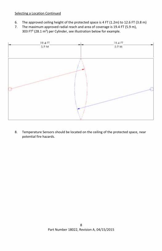
Selecting a Location Continued
6. The approved ceiling height of the protected space is 4 FT (1.2m) to 12.6 FT (3.8 m) 7. The maximum approved radial reach and area of coverage is 19.4 FT (5.9 m),
303 FT² (28.1 m²) per Cylinder, see illustration below for example.
8. Temperature Sensors should be located on the ceiling of the protected space, near
potential fire hazards.

9 Part Number 18022, Revision A, 04/15/2015
Mounting Fireboy system
DANGER:
ACCIDENTAL DISCHARGE DURING HANDLING OR INSTALLATION MAY CAUSE SERIOUS INJURY. DO NOT LIFT, CARRY, OR HANDLE BY ACTUATOR, PRESSURE SWITCH, OR CABLE. WEAR EYE PROTECTION WHEN INSTALLING OR SERVICING CYLINDER. DO NOT REMOVE SAFETY NUTS UNTIL SYSTEM IS FULLY INSTALLED. REFER TO HEALTH AND SAFETY SECTION (PAGE 29).
Mounting Extinguisher 1. Use appropriate size and length bolts and lock washers and fasten to bulk head. 2. Mount the Shelf Brackets using the 6 mounting holes. Be sure to include unistrut
while mounting bracket. 3. Locate upper bracket 1” below the top weld seam of cylinder. Be sure to include
spacer while mounting unistrut. 4. Install Clamps in Unistrut and tighten with provided fasteners. 5. Models 2500-4000 will include a third clamp, to be located at the midpoint
between the other two clamps.
0.56” Dia. Through Hole 10 Places
Shelf Bracket (P/N: 93050-100)
Unistrut (P/N: 93053)
Clamp (P/N: 93054)
Spacer (P/N: 93052)
Washer (P/N: 61007) Nut (P/N: 61009)
Bolt (P/N: 61006)

10 Part Number 18022, Revision A, 04/15/2015
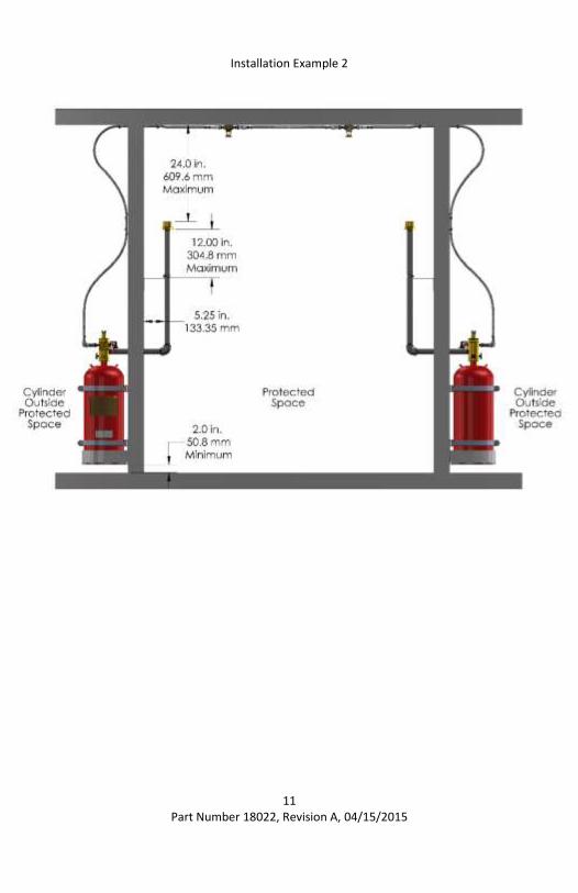
Installing Discharge Piping
1. Pipe must be 1in NPT, schedule 40. Galvanized, Stainless, and Black Steel Pipe are acceptable.
2. Total pipe length cannot exceed 76 in (193.1 cm). Minimum individual pipe length is 4 in (10.2 cm). Maximum individual pipe length is 72 in (182.9 cm).
3. Piping must include one 90° elbow. 4. Teflon Tape Mil-Spec T-27730A should be used for all threaded connections. 5. Install Nozzle with indicator arrow pointed away and perpendicular to cylinder
mounting wall.
Installation Example 1
11 Part Number 18022, Revision A, 04/15/2015
Installation Example 2

12 Part Number 18022, Revision A, 04/15/2015
Installing Discharge Piping Supports
1. At least one Pipe Support must be used on vertical pipe run, no more than 12” from discharge nozzle. Two Pipe Supports must be used on vertical pipe runs greater than 40”.
2. Use appropriate size and length bolts and lock washers and fasten to bulk head. 3. Mount the Pipe Support using the 4 mounting holes. 4. Lower Pipe Support, if required, should be placed at the midpoint between the top
Pipe Support and the Elbow of the Discharge Piping.
Installing Temperature Sensors
1. Locate Temperature Sensors in previously determined location. 2. Use appropriate size and length hardware to mount to ceiling. 3. Mount the Temperature Sensor using the 4 mounting holes.
Discharge Nozzle
Upper Pipe Support (P/N: 100360) No further than 12” from Discharge Nozzle
Elbow
Lower Pipe Support (P/N: 100360) Midpoint of Upper Pipe Support and Elbow
0.19” Mounting Holes
13 Part Number 18022, Revision A, 04/15/2015
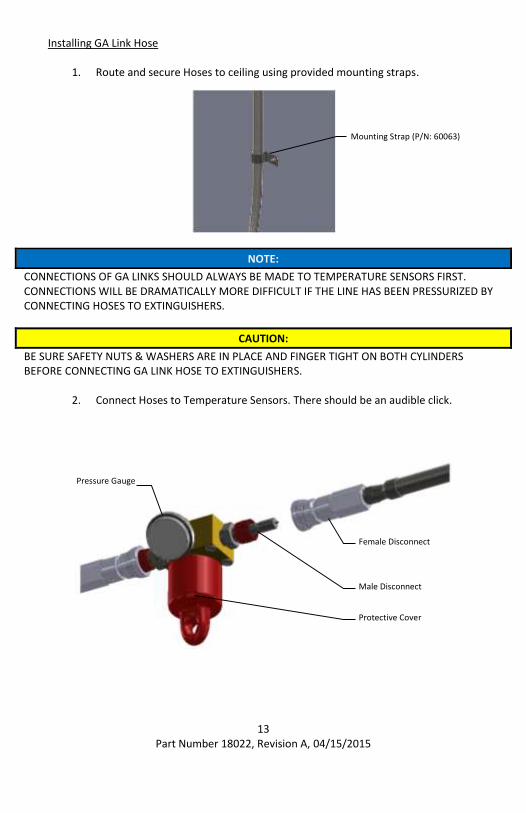
Installing GA Link Hose
1. Route and secure Hoses to ceiling using provided mounting straps.
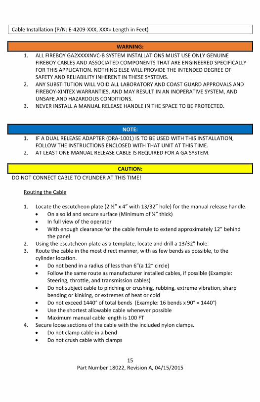
NOTE:
CONNECTIONS OF GA LINKS SHOULD ALWAYS BE MADE TO TEMPERATURE SENSORS FIRST. CONNECTIONS WILL BE DRAMATICALLY MORE DIFFICULT IF THE LINE HAS BEEN PRESSURIZED BY CONNECTING HOSES TO EXTINGUISHERS.
CAUTION:
BE SURE SAFETY NUTS & WASHERS ARE IN PLACE AND FINGER TIGHT ON BOTH CYLINDERS BEFORE CONNECTING GA LINK HOSE TO EXTINGUISHERS.
2. Connect Hoses to Temperature Sensors. There should be an audible click.
Female Disconnect
Male Disconnect
Pressure Gauge
Protective Cover
Mounting Strap (P/N: 60063)

14 Part Number 18022, Revision A, 04/15/2015
Installing GA Link Hose Continued
3. Connect Hose to Extinguishers. There should be an audible click. The male connector will be under pressure, which will require more force to make the connection.
4. Once all connections have been made, wait approximately 15 minutes and verify that the reading on the pressure gauge on Temperature Sensors is in the Green zone.
Pressure Gauge
Extinguisher Male Disconnect
Hose Female Disconnect
15 Part Number 18022, Revision A, 04/15/2015
Cable Installation (P/N: E-4209-XXX, XXX= Length in Feet)
WARNING:
1. ALL FIREBOY GA2XXXXNVC-B SYSTEM INSTALLATIONS MUST USE ONLY GENUINE FIREBOY CABLES AND ASSOCIATED COMPONENTS THAT ARE ENGINEERED SPECIFICALLY FOR THIS APPLICATION. NOTHING ELSE WILL PROVIDE THE INTENDED DEGREE OF SAFETY AND RELIABILITY INHERENT IN THESE SYSTEMS.
2. ANY SUBSTITUTION WILL VOID ALL LABORATORY AND COAST GUARD APPROVALS AND FIREBOY-XINTEX WARRANTIES, AND MAY RESULT IN AN INOPERATIVE SYSTEM, AND UNSAFE AND HAZARDOUS CONDITIONS.
3. NEVER INSTALL A MANUAL RELEASE HANDLE IN THE SPACE TO BE PROTECTED.
NOTE:
1. IF A DUAL RELEASE ADAPTER (DRA-1001) IS TO BE USED WITH THIS INSTALLATION, FOLLOW THE INSTRUCTIONS ENCLOSED WITH THAT UNIT AT THIS TIME.
2. AT LEAST ONE MANUAL RELEASE CABLE IS REQUIRED FOR A GA SYSTEM.
CAUTION:
DO NOT CONNECT CABLE TO CYLINDER AT THIS TIME! Routing the Cable 1. Locate the escutcheon plate (2 ½” x 4” with 13/32” hole) for the manual release handle.
On a solid and secure surface (Minimum of ¼” thick)
In full view of the operator
With enough clearance for the cable ferrule to extend approximately 12” behind the panel
2. Using the escutcheon plate as a template, locate and drill a 13/32” hole. 3. Route the cable in the most direct manner, with as few bends as possible, to the
cylinder location.
Do not bend in a radius of less than 6”(a 12“ circle)
Follow the same route as manufacturer installed cables, if possible (Example: Steering, throttle, and transmission cables)
Do not subject cable to pinching or crushing, rubbing, extreme vibration, sharp bending or kinking, or extremes of heat or cold
Do not exceed 1440° of total bends (Example: 16 bends x 90° = 1440°)
Use the shortest allowable cable whenever possible
Maximum manual cable length is 100 FT 4. Secure loose sections of the cable with the included nylon clamps.
Do not clamp cable in a bend
Do not crush cable with clamps

16 Part Number 18022, Revision A, 04/15/2015
Escutcheon Panel and T-Handle
Cable P/N: 90033-XXX
3/8”-24 Nut P/N: 50002
Safety Pin P/N: ALPP-0247-01
Helm
13/32” Hole
Lock Washer P/N: 14104
Escutcheon Plate P/N: EP-MR-02-A
Ferrule P/N: F-1001-01
T-Handle P/N: K-2016R
Drill 13/32” hole in desired location for Pull Station.
O-Ring P/N: AS 568-202
3/8”-24 Nut
Lock Washer
Helm
Peel off paper and Press escutcheon plate firmly press in place. Install 3/8”-24 Nut and Lock Washer on Cable and position through hole. Leave enough space to tighten later.
NOTE: Temperature must be above +50°F (10°C) for proper adhesion.
Escutcheon Plate
Thread Ferrule onto Cable using 3 full revolutions. Adjust Ferrule so that holes are parallel to the floor and tighten Nut.
Note: Do NOT thread further than Ferrule’s internal threads.
Ferrule

17 Part Number 18022, Revision A, 04/15/2015
Push T-Handle into Ferrule to align through holes. There will be resistance from O-Ring.
With Cable DISCONNECTED from extinguisher, take this time to test Cable operation. Cable should slide freely.
O-Ring
T-Handle Slide O-Ring onto Cable. Thread T-Handle onto Cable 7 Full turns. Make sure not to obstruct through hole.
Tamper Seal
Pin
Insert Pin into Ferrule and T-Handle through holes. Wrap Tamper Seal through loop of Safety Pin and around Ferrule. Insert end of seal into side marked “ENTER” and pull tight.

18 Part Number 18022, Revision A, 04/15/2015
Connecting Cable to Cylinder
Safety Pin
Safety Nut & Washer
CAUTION:
1. EXTINGUISHER SHOULD BE SECURELY MOUNTED. 2. CABLE SHOULD BE ROUTED AND SECURED. 3. BE SURE THE SAFETY PIN IS IN PLACE. 4. BE SURE SAFETY NUT & WASHER ARE IN PLACE AND FINGER
TIGHT.
Insert extinguisher end of Cable through hole in Actuator Block past retaining slot on Cable.
Cable Retaining Slot
Actuation Block

19 Part Number 18022, Revision A, 04/15/2015
Insert S-Hook into hole at the Bottom of Actuation Lever.
S-Hook
Actuation Lever
Align retaining slot of Cable with retaining slot of Actuation Block.
Actuation Block Retaining Slot
S-Hook
Actuation Lever
20 Part Number 18022, Revision A, 04/15/2015
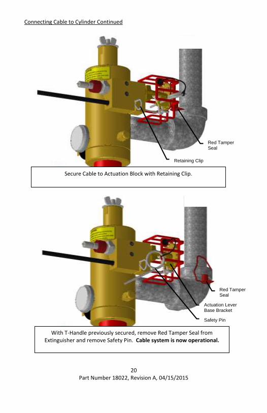
Connecting Cable to Cylinder Continued
Secure Cable to Actuation Block with Retaining Clip.
Retaining Clip
Red Tamper Seal
With T-Handle previously secured, remove Red Tamper Seal from Extinguisher and remove Safety Pin. Cable system is now operational.
Safety Pin
Actuation Lever Base Bracket
Red Tamper Seal
21 Part Number 18022, Revision A, 04/15/2015
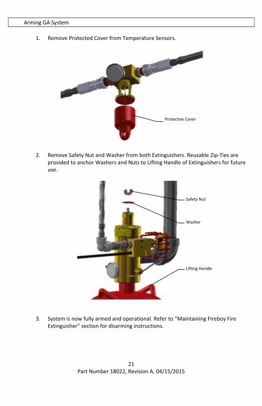
Arming GA System
1. Remove Protected Cover from Temperature Sensors.
2. Remove Safety Nut and Washer from both Extinguishers. Reusable Zip-Ties are
provided to anchor Washers and Nuts to Lifting Handle of Extinguishers for future use.
3. System is now fully armed and operational. Refer to “Maintaining Fireboy Fire
Extinguisher” section for disarming instructions.
Safety Nut
Washer
Lifting Handle
Protective Cover
22 Part Number 18022, Revision A, 04/15/2015
Accommodating Diesel Engines
WARNING:
FAILURE TO INSTALL AN ENGINE SHUTDOWN BOX WITH A FIREBOY SYSTEM IN ANY DIESEL ENGINE APPLICATION IMPEDES THE FIRE EXTINGUISHER AND MAY PREVENT FIRE EXTINGUISHMENT.
CAUTION:
FAILURE TO CONNECT A POWERED VENTILATION SYSTEM IN THE MANNER DESCRIBED BELOW IMPEDES FIRE EXTINGUISHER AND MAY PREVENT FIRE FROM BEING EXTINGUISHED.
1. Automatic Engine Shutdown units are available through your Fireboy-Xintex
distributor, dealer or retailer in three, five, eight, and ten circuit models. 2. Follow the installation instructions included with the Automatic Engine Shutdown
for proper installation. 3. Technical Support for Automatic Engine Shutdowns is available by calling Fireboy-
Xintex or visiting our website at www.fireboy-xintex.com.
Installing Indicator Lamp (P/N: 90107)
Mounting Indicator Lamp
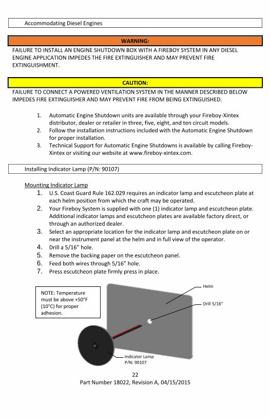
1. U.S. Coast Guard Rule 162.029 requires an indicator lamp and escutcheon plate at each helm position from which the craft may be operated.
2. Your Fireboy System is supplied with one (1) indicator lamp and escutcheon plate. Additional indicator lamps and escutcheon plates are available factory direct, or through an authorized dealer.
3. Select an appropriate location for the indicator lamp and escutcheon plate on or near the instrument panel at the helm and in full view of the operator.
4. Drill a 5/16” hole.
5. Remove the backing paper on the escutcheon panel.
6. Feed both wires through 5/16” hole.
7. Press escutcheon plate firmly press in place.
Drill 5/16”
Helm
Indicator Lamp P/N: 90107
NOTE: Temperature must be above +50°F (10°C) for proper adhesion.

23 Part Number 18022, Revision A, 04/15/2015
NOTE:
THE INDICATOR LAMP SUPPLIED IS FOR 12 VDC USE ONLY
WARNING:
1. AN ELECTRICAL SHORT MAY RESULT IN ELECTRICAL BURN, INJURY OR FIRE 2. BEFORE ATTEMPTING TO WIRE THE INDICATOR LAMP, TURN OFF ALL ELECTRICAL
CURRENT TO THE IGNITION SWITCH 3. ALL FIREBOY WIRING MUST COMPLY WITH THE AMERICAN BOAT AND YACHT
COUNCIL STANDARD E-11, TITLED AC AND DC ELECTRICAL SYSTEMS ON BOATS, AVAILABLE FROM ABYC, WWW.ABYCINC.ORG
Wiring Indicator Lamp
1. Review all wiring instructions below. 2. Consult a qualified marine electrician if you have any doubts about your ability to
safely and properly complete the wiring. Ignition systems and electrical systems vary from boat to boat, and the directions which follow, may not apply to your boat.
3. Assemble the supplies you will need that are not included with your Fireboy System.
The necessary length of insulated 16 gauge (minimum) stranded wire
A one-half (.5) ampere in-line fuse and fuse holder or circuit breaker
Properly sized insulated crimp-on wire connectors 4. Connect one lead of the fuse to the “ON” position of the starter switch. 5. Connect the other lead of the fuse to the red (+) wire of the LED indicator lamp. 6. Connect the black (-) wire of the indicator lamp to one of the pigtail wires on the
Fireboy System (as shown below). 7. Do not reverse red and black wire, indicator lamp will not function. 8. Connect the remaining wire from the Fireboy system to ground.
ON OFF
START
IGNITION
LED INDICATOR
LAMP
0.5 AMP RED (+)
BLACK (-)
24 Part Number 18022, Revision A, 04/15/2015
Connecting to Powered Ventilation
Engine compartments not equipped with a powered ventilation system require no further wiring. If the engine compartment is equipped with a powered ventilation system, U.S. Coast Guard Rule 162.029 requires that the ground connection of the ventilation system be connected to the Fireboy system.
CAUTION:
FAILURE TO CONNECT A POWERED VENTILATION SYSTEM IN THE MANNER DESCRIBED BELOW IMPEDES FIRE EXTINGUISHER AND MAY PREVENT FIRE FROM BEING EXTINGUISHED.
Powered Ventilation Systems (Blowers) 1. Determine the maximum current draw of the powered ventilation system. 2. For current draw not exceeding 5 amps connect the negative (-) wire from the
ventilation blower to the pressure switch at the same point as the indicator lamp. 3. For current draw exceeding 5 amps, use a Fireboy Automatic Engine Shutdown
system.
NOTE:
THE ESCUTCHEON PLATE LED IS CONNECTED TO THE PRESSURE SWITCH AT THE SAME POINT THAT AUXILIARY DEVICES CAN BE CONNECTED. CARE MUST BE TAKEN WHEN WIRING OTHER DEVICES TO THE PRESSURE SWITCH TO ENSURE THE PRESENCE OF THE LED DOES NOT AFFECT THE OPERATION OF THE DEVICE. CONTACT FIREBOY-XINTEX TECHNICAL SUPPORT REGARDING ANY INSTALLATION QUESTIONS.
Use of indicator lamp
The Fireboy System indicator lamp is designed to announce to the helmsman the state of the fire extinguisher when the ignition key is in the ON position.
A GLOWING green light indicates the Fireboy system is CHARGED.
A NON GLOWING light indicates the Fireboy system is DISCHARGED or is in need of service due to a loss in pressure.

25 Part Number 18022, Revision A, 04/15/2015
Installation Checklist
Verified Volume of Protected Space
Verified Extinguisher Model is for Volume of Protected Space
Mounted Extinguisher according to installation instructions
Located extinguisher according to installation instructions
Located Temperature Sensors according to installation instructions
Orientated extinguisher according to installation instructions
Nozzle is installed no greater than 24 inches from ceiling
Secured Extinguisher Bracket according to installation instructions
Installed Discharge Piping according to installation instructions
Installed Discharge Piping Supports according to installation instructions
Installed Temperature Sensor according to installation instructions
Installed GA Link Hose according to installation instructions
Verified reading of Pressure Gauge on Temperature Sensor
Installed Cable According to installation instructions
Located Manual Release Handle according to installation instructions
Routed Cable according to installation instructions
No more than Sixteen 90° Bends (16 x 90° = 1440°)
Secured Cable according to installation instructions
Installed Manual Release Handle according to installation instructions
Connected Cable to extinguisher according to installation instructions
Removed Safety Pin from Extinguisher (Cable System is operational)
Armed GA System according to installation instructions
Removed Protected Cover from Temperature Sensor
Removed Safety Nut & Washer from Extinguishers and stored for future use
Installed Indicator Lamp According to installation instructions
Located Indicator Lamp according to installation instructions
Mounted Indicator Lamp according to installation instructions
Wired Indicator Lamp according to installation instructions
Review Maintenance of system
Review Health and Safety Section of Manual
Installed Fireboy Automatic Engine Shutdown if required
26 Part Number 18022, Revision A, 04/15/2015
Maintaining Fireboy Extinguishing System
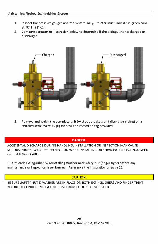
1. Inspect the pressure gauges and the system daily. Pointer must indicate in green zone
at 70° F (21° C). 2. Compare actuator to illustration below to determine if the extinguisher is charged or
discharged.
3. Remove and weigh the complete unit (without brackets and discharge piping) on a certified scale every six (6) months and record on tag provided.
DANGER:
ACCIDENTAL DISCHARGE DURING HANDLING, INSTALLATION OR INSPECTION MAY CAUSE SERIOUS INJURY. WEAR EYE PROTECTION WHEN INSTALLING OR SERVICING FIRE EXTINGUISHER OR DISCHARGE CABLE. Disarm each Extinguisher by reinstalling Washer and Safety Nut (finger tight) before any maintenance or inspection is performed. (Reference the illustration on page 21)
CAUTION:
BE SURE SAFETY NUT & WASHER ARE IN PLACE ON BOTH EXTINGUISHERS AND FINGER TIGHT BEFORE DISCONNECTING GA LINK HOSE FROM EITHER EXTINGUISHER.
Charged Discharged

27 Part Number 18022, Revision A, 04/15/2015
Disconnect GA Link Hose by pushing the raised portion of the female disconnect toward the male disconnect.
Remove Discharge Piping and Pipe Supports. Remove and inspect manual discharge cable annually when inspecting the fire extinguisher.
Do not remove the safety pin on the T-handle when disconnecting the manual discharge cable from the fire extinguisher manifold.
Carefully reinstall Safety Nut & Washer to threaded portion on top of extinguisher valve (hand tight). (Reference the illustration on page 21)
Carefully reinstall safety pin through actuation lever. Safety pin should secure actuation lever in actuation lever base. (See Page 20)
Remove the retaining clip securing the cable located at the slot in the actuation block of extinguisher valve. (See Page 20)
Carefully push the cable from the backside of the manifold towards the actuator far enough to allow the flexible center strand to bend.
Remove the “S” hook from the actuation lever.
Once the “S” hook is free of the actuation lever, pull the cable out and away from the manifold.
4. Remove fire extinguisher from service immediately for repair or replacement if
measured gross weight is greater than 5% below what is stated on unit’s label (Label Gross Weight x .95 = Minimum Allowable Weight).
5. Inspect cylinder in accordance with CGA C-6, every 5 years OR have cylinder hydrostatic tested every 12 years.
Refer to “Marine Installation Instructions” and “Cable Installation” to reinstall and re-arm Extinguishers and Manual Cable after maintenance or service is complete.
Female Disconnect Male Disconnect
Safety Nut & Washer
28 Part Number 18022, Revision A, 04/15/2015
Maintaining the Indicator Lamp Circuit
Should the indicator lamp fail to come ON when the ignition key is ON 1. Check the pressure gauge and actuator to see if the system has adequate pressure or
has been discharged. 2. Check fuse. 3. Using a continuity tester, check the electrical pressure switch on the system bottle itself:
Pull the connectors off the spade terminals and place the probes of the continuity tester directly on the spade connectors
A closed circuit indicates a functioning pressure switch 4. Check the continuity of the remaining wiring circuit. 5. The indicator lamp is an LED (light emitting diode) and cannot be tested with a
continuity tester. A simple method to test LED’s is to remove the lamp and touch the Red wire to the + terminal and the black wire to the – terminal of an ordinary 9 volt battery.
6. Should the continuity of the pressure switch indicate an open circuit, the system will have to be returned to the factory for either replacement or repair, depending upon the model involved.
Additional Equipment
Coast Guard Regulation 162.029 requires an indicator lamp be installed at each helm station from which the vessel may be operated.
An Automatic Discharge Alarm provides both an audible and visual alarm when the system discharges. Includes a 2” round instrument with a simple three (3) wire hookup. Automatic Engine Shutdown/Override System is required for use with Fireboy systems in diesel powered craft. These additional equipment options are available factory direct or through your dealer. Outside the U.S.A. and Canada, see your dealer.
29 Part Number 18022, Revision A, 04/15/2015
Health and Safety
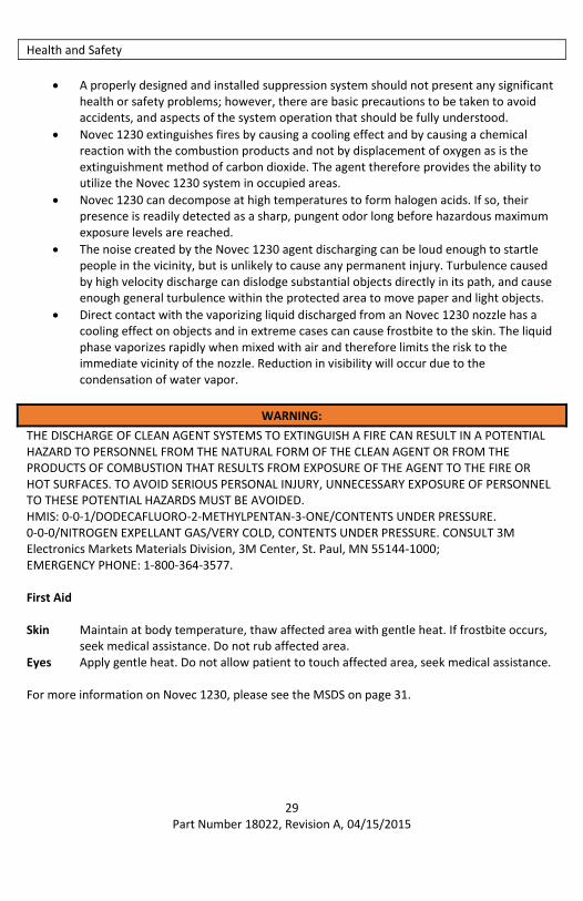
A properly designed and installed suppression system should not present any significant health or safety problems; however, there are basic precautions to be taken to avoid accidents, and aspects of the system operation that should be fully understood.
Novec 1230 extinguishes fires by causing a cooling effect and by causing a chemical reaction with the combustion products and not by displacement of oxygen as is the extinguishment method of carbon dioxide. The agent therefore provides the ability to utilize the Novec 1230 system in occupied areas.
Novec 1230 can decompose at high temperatures to form halogen acids. If so, their presence is readily detected as a sharp, pungent odor long before hazardous maximum exposure levels are reached.
The noise created by the Novec 1230 agent discharging can be loud enough to startle people in the vicinity, but is unlikely to cause any permanent injury. Turbulence caused by high velocity discharge can dislodge substantial objects directly in its path, and cause enough general turbulence within the protected area to move paper and light objects.
Direct contact with the vaporizing liquid discharged from an Novec 1230 nozzle has a cooling effect on objects and in extreme cases can cause frostbite to the skin. The liquid phase vaporizes rapidly when mixed with air and therefore limits the risk to the immediate vicinity of the nozzle. Reduction in visibility will occur due to the condensation of water vapor.
WARNING:
THE DISCHARGE OF CLEAN AGENT SYSTEMS TO EXTINGUISH A FIRE CAN RESULT IN A POTENTIAL HAZARD TO PERSONNEL FROM THE NATURAL FORM OF THE CLEAN AGENT OR FROM THE PRODUCTS OF COMBUSTION THAT RESULTS FROM EXPOSURE OF THE AGENT TO THE FIRE OR HOT SURFACES. TO AVOID SERIOUS PERSONAL INJURY, UNNECESSARY EXPOSURE OF PERSONNEL TO THESE POTENTIAL HAZARDS MUST BE AVOIDED. HMIS: 0-0-1/DODECAFLUORO-2-METHYLPENTAN-3-ONE/CONTENTS UNDER PRESSURE. 0-0-0/NITROGEN EXPELLANT GAS/VERY COLD, CONTENTS UNDER PRESSURE. CONSULT 3M Electronics Markets Materials Division, 3M Center, St. Paul, MN 55144-1000; EMERGENCY PHONE: 1-800-364-3577. First Aid Skin Maintain at body temperature, thaw affected area with gentle heat. If frostbite occurs,
seek medical assistance. Do not rub affected area. Eyes Apply gentle heat. Do not allow patient to touch affected area, seek medical assistance. For more information on Novec 1230, please see the MSDS on page 31.
30 Part Number 18022, Revision A, 04/15/2015
Health and Safety Continued
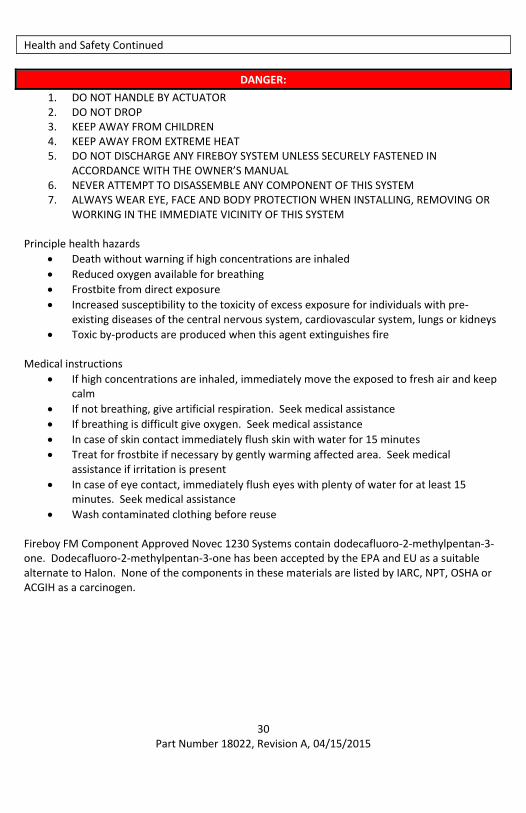
DANGER:
1. DO NOT HANDLE BY ACTUATOR 2. DO NOT DROP 3. KEEP AWAY FROM CHILDREN 4. KEEP AWAY FROM EXTREME HEAT 5. DO NOT DISCHARGE ANY FIREBOY SYSTEM UNLESS SECURELY FASTENED IN
ACCORDANCE WITH THE OWNER’S MANUAL 6. NEVER ATTEMPT TO DISASSEMBLE ANY COMPONENT OF THIS SYSTEM 7. ALWAYS WEAR EYE, FACE AND BODY PROTECTION WHEN INSTALLING, REMOVING OR
WORKING IN THE IMMEDIATE VICINITY OF THIS SYSTEM Principle health hazards
Death without warning if high concentrations are inhaled
Reduced oxygen available for breathing
Frostbite from direct exposure
Increased susceptibility to the toxicity of excess exposure for individuals with pre-existing diseases of the central nervous system, cardiovascular system, lungs or kidneys
Toxic by-products are produced when this agent extinguishes fire Medical instructions
If high concentrations are inhaled, immediately move the exposed to fresh air and keep calm
If not breathing, give artificial respiration. Seek medical assistance
If breathing is difficult give oxygen. Seek medical assistance
In case of skin contact immediately flush skin with water for 15 minutes
Treat for frostbite if necessary by gently warming affected area. Seek medical assistance if irritation is present
In case of eye contact, immediately flush eyes with plenty of water for at least 15 minutes. Seek medical assistance
Wash contaminated clothing before reuse Fireboy FM Component Approved Novec 1230 Systems contain dodecafluoro-2-methylpentan-3-one. Dodecafluoro-2-methylpentan-3-one has been accepted by the EPA and EU as a suitable alternate to Halon. None of the components in these materials are listed by IARC, NPT, OSHA or ACGIH as a carcinogen.
31 Part Number 18022, Revision A, 04/15/2015
MSDS
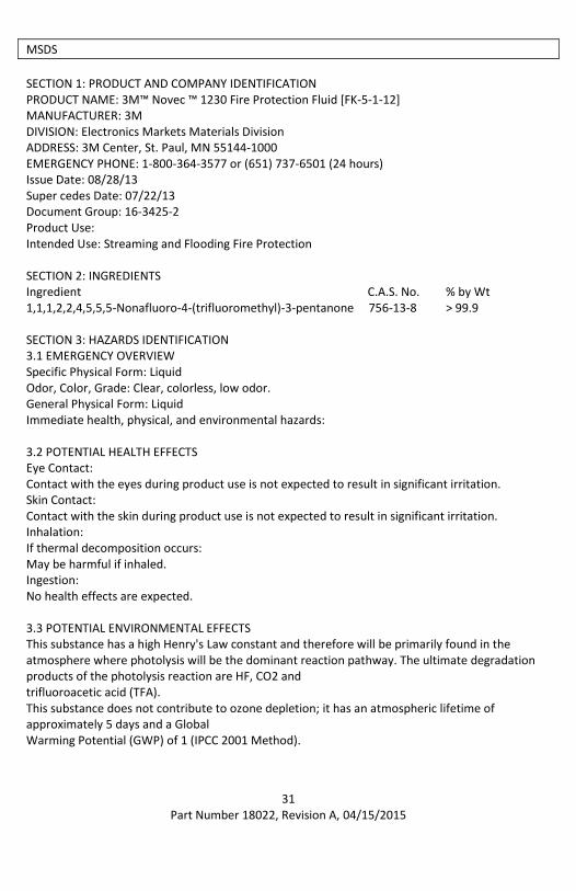
SECTION 1: PRODUCT AND COMPANY IDENTIFICATION PRODUCT NAME: 3M™ Novec ™ 1230 Fire Protection Fluid [FK-5-1-12] MANUFACTURER: 3M DIVISION: Electronics Markets Materials Division ADDRESS: 3M Center, St. Paul, MN 55144-1000 EMERGENCY PHONE: 1-800-364-3577 or (651) 737-6501 (24 hours) Issue Date: 08/28/13 Super cedes Date: 07/22/13 Document Group: 16-3425-2 Product Use: Intended Use: Streaming and Flooding Fire Protection SECTION 2: INGREDIENTS Ingredient C.A.S. No. % by Wt 1,1,1,2,2,4,5,5,5-Nonafluoro-4-(trifluoromethyl)-3-pentanone 756-13-8 > 99.9 SECTION 3: HAZARDS IDENTIFICATION 3.1 EMERGENCY OVERVIEW Specific Physical Form: Liquid Odor, Color, Grade: Clear, colorless, low odor. General Physical Form: Liquid Immediate health, physical, and environmental hazards: 3.2 POTENTIAL HEALTH EFFECTS Eye Contact: Contact with the eyes during product use is not expected to result in significant irritation. Skin Contact: Contact with the skin during product use is not expected to result in significant irritation. Inhalation: If thermal decomposition occurs: May be harmful if inhaled. Ingestion: No health effects are expected. 3.3 POTENTIAL ENVIRONMENTAL EFFECTS This substance has a high Henry's Law constant and therefore will be primarily found in the atmosphere where photolysis will be the dominant reaction pathway. The ultimate degradation products of the photolysis reaction are HF, CO2 and trifluoroacetic acid (TFA). This substance does not contribute to ozone depletion; it has an atmospheric lifetime of approximately 5 days and a Global Warming Potential (GWP) of 1 (IPCC 2001 Method).

32 Part Number 18022, Revision A, 04/15/2015
MSDS Continued
SECTION 4: FIRST AID MEASURES 4.1 FIRST AID PROCEDURES The following first aid recommendations are based on an assumption that appropriate personal and industrial hygiene practices are followed. Eye Contact: No need for first aid is anticipated. Skin Contact: No need for first aid is anticipated. Inhalation: If signs/symptoms develop, remove person to fresh air. If signs/symptoms persist, get medical attention. If Swallowed: No need for first aid is anticipated. SECTION 5: FIRE FIGHTING MEASURES 5.1 FLAMMABLE PROPERTIES Auto ignition temperature Not Applicable Flash Point No flash point Flammable Limits (LEL): None detected Flammable Limits (UEL): None detected 5.2 EXTINGUISHING MEDIA Product is a fire-extinguishing agent. 5.3 PROTECTION OF FIRE FIGHTERS Special Fire Fighting Procedures: Exposure to extreme heat can give rise to thermal decomposition. Wear full protective equipment (Bunker Gear) and a self-contained breathing apparatus (SCBA). Unusual Fire and Explosion Hazards: No unusual effects are anticipated during fire extinguishing operations. Avoid breathing the products and substances that may result from the thermal decomposition of the product or the other substances in the fire zone. Keep containers cool with water spray when exposed to fire to avoid rupture. Note: See STABILITY AND REACTIVITY (SECTION 10) for hazardous combustion and thermal decomposition information. SECTION 6: ACCIDENTAL RELEASE MEASURES 6.1. Personal precautions, protective equipment and emergency procedures Ventilate the area with fresh air. 6.2. Environmental precautions For larger spills, cover drains and build dikes to prevent entry into sewer systems or bodies of water. Collect the resulting residue containing solution. Place in a metal container approved for transportation by appropriate authorities. Dispose of collected material as soon as possible. Clean-up methods

33 Part Number 18022, Revision A, 04/15/2015
Observe precautions from other sections. Call 3M- HELPS line (1-800-364-3577) for more information on handling and managing the spill. Contain spill. Working from around the edges of the spill inward, cover with bentonite, vermiculite, or commercially available inorganic absorbent material. Mix in sufficient absorbent until it appears dry. Collect as much of the spilled material as possible. Clean up residue. Clean up residue with detergent and water. Seal the container. In the event of a release of this material, the user should determine if the release qualifies as reportable according to local, state, and federal regulations. SECTION 7: HANDLING AND STORAGE 7.1 HANDLING For industrial or professional use only. Contents may be under pressure, open carefully. Do not breathe thermal decomposition products. 7.2 STORAGE Keep container in well-ventilated area. Store out of direct sunlight. Store away from heat. Store away from strong bases, amines, and alcohols. SECTION 8: EXPOSURE CONTROLS/PERSONAL PROTECTION 8.1 ENGINEERING CONTROLS Provide appropriate local exhaust ventilation on open containers. For those situations where the material might be exposed to extreme overheating due to misuse or equipment failure, use with appropriate local exhaust ventilation sufficient to maintain levels of thermal decomposition products below their exposure guidelines. 8.2 PERSONAL PROTECTIVE EQUIPMENT (PPE) 8.2.1 Eye/Face Protection Not applicable. 8.2.2 Skin Protection Not applicable. Gloves are not required. Select and use gloves and/or protective clothing to prevent skin contact based on the results of an exposure assessment. Consult with your glove and/or protective clothing manufacturer for selection of appropriate compatible materials. Gloves made from the following material(s) are recommended: Butyl Rubber 8.2.3 Respiratory Protection As a good industrial hygiene practice: Avoid breathing of vapors, mists or spray. Under normal use conditions, airborne exposures are not expected to be significant enough to require respiratory protection. If thermal decomposition occurs: Do not breathe vapors. If thermal decomposition occurs, wear supplied air respiratory protection.
34 Part Number 18022, Revision A, 04/15/2015
MSDS Continued
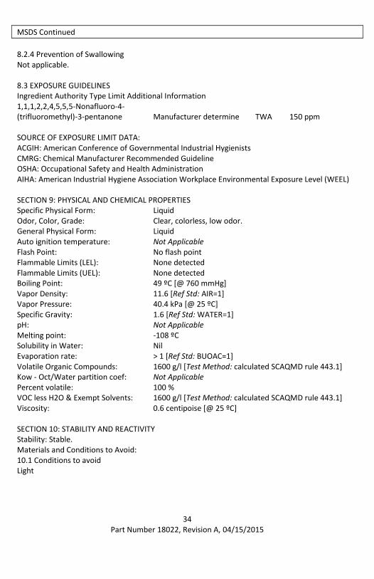
8.2.4 Prevention of Swallowing Not applicable. 8.3 EXPOSURE GUIDELINES Ingredient Authority Type Limit Additional Information 1,1,1,2,2,4,5,5,5-Nonafluoro-4- (trifluoromethyl)-3-pentanone Manufacturer determine TWA 150 ppm SOURCE OF EXPOSURE LIMIT DATA: ACGIH: American Conference of Governmental Industrial Hygienists CMRG: Chemical Manufacturer Recommended Guideline OSHA: Occupational Safety and Health Administration AIHA: American Industrial Hygiene Association Workplace Environmental Exposure Level (WEEL) SECTION 9: PHYSICAL AND CHEMICAL PROPERTIES Specific Physical Form: Liquid Odor, Color, Grade: Clear, colorless, low odor. General Physical Form: Liquid Auto ignition temperature: Not Applicable Flash Point: No flash point Flammable Limits (LEL): None detected Flammable Limits (UEL): None detected Boiling Point: 49 ºC [@ 760 mmHg] Vapor Density: 11.6 [Ref Std: AIR=1] Vapor Pressure: 40.4 kPa [@ 25 ºC] Specific Gravity: 1.6 [Ref Std: WATER=1] pH: Not Applicable Melting point: -108 ºC Solubility in Water: Nil Evaporation rate: > 1 [Ref Std: BUOAC=1] Volatile Organic Compounds: 1600 g/l [Test Method: calculated SCAQMD rule 443.1] Kow - Oct/Water partition coef: Not Applicable Percent volatile: 100 % VOC less H2O & Exempt Solvents: 1600 g/l [Test Method: calculated SCAQMD rule 443.1] Viscosity: 0.6 centipoise [@ 25 ºC] SECTION 10: STABILITY AND REACTIVITY Stability: Stable. Materials and Conditions to Avoid: 10.1 Conditions to avoid Light
35 Part Number 18022, Revision A, 04/15/2015
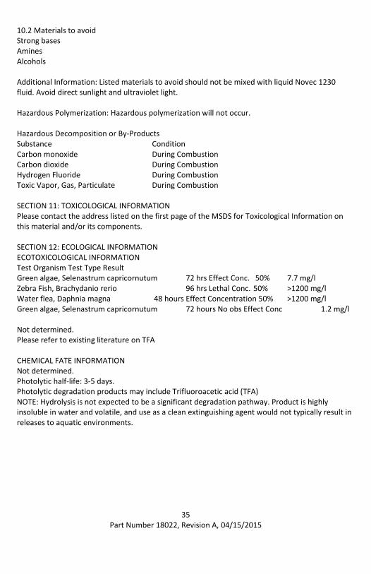
10.2 Materials to avoid Strong bases Amines Alcohols Additional Information: Listed materials to avoid should not be mixed with liquid Novec 1230 fluid. Avoid direct sunlight and ultraviolet light. Hazardous Polymerization: Hazardous polymerization will not occur. Hazardous Decomposition or By-Products Substance Condition Carbon monoxide During Combustion Carbon dioxide During Combustion Hydrogen Fluoride During Combustion Toxic Vapor, Gas, Particulate During Combustion SECTION 11: TOXICOLOGICAL INFORMATION Please contact the address listed on the first page of the MSDS for Toxicological Information on this material and/or its components. SECTION 12: ECOLOGICAL INFORMATION ECOTOXICOLOGICAL INFORMATION Test Organism Test Type Result Green algae, Selenastrum capricornutum 72 hrs Effect Conc. 50% 7.7 mg/l Zebra Fish, Brachydanio rerio 96 hrs Lethal Conc. 50% >1200 mg/l Water flea, Daphnia magna 48 hours Effect Concentration 50% >1200 mg/l Green algae, Selenastrum capricornutum 72 hours No obs Effect Conc 1.2 mg/l Not determined. Please refer to existing literature on TFA CHEMICAL FATE INFORMATION Not determined. Photolytic half-life: 3-5 days. Photolytic degradation products may include Trifluoroacetic acid (TFA) NOTE: Hydrolysis is not expected to be a significant degradation pathway. Product is highly insoluble in water and volatile, and use as a clean extinguishing agent would not typically result in releases to aquatic environments.

36 Part Number 18022, Revision A, 04/15/2015
MSDS Continued
SECTION 13: DISPOSAL CONSIDERATIONS Waste Disposal Method: Reclaim if feasible. To reclaim or return, contact your 3M sales representative. Incinerate in an industrial or commercial facility in the presence of a combustible material. As a disposal alternative, dispose of waste product in a facility permitted to accept chemical waste. Combustion products will include HF. Facility must be capable of handling halogenated materials. For information on product return, contact your distributor. EPA Hazardous Waste Number (RCRA): Not regulated Since regulations vary, consult applicable regulations or authorities before disposal. SECTION 14: TRANSPORT INFORMATION ID Number(s): 98-0212-3031-7, 98-0212-3201-6, 98-0212-3203-2, 98-0212-3217-2, 98-0212-3371-7, 98-0212-3414-5, 98-0212-3588-6 Novec 1230 by itself is not regulated by DOT Or – If packaged as a charged Fire Extinguisher…
DOT UN number: 1044
Proper shipping name: Fire Extinguishers Class: 2.2 (Non-Flammable Gas) Labelling No. : 2.2
IATA_C UN number: 1044 Proper shipping name: Fire Extinguishers Class: 2.2 (Non-Flammable Gas) Labelling No. : 2.2
IMDG UN number: 1044 Proper shipping name: Fire Extinguishers Class: 2.2 (Non-Flammable Gas)
Labelling No. : 2.2

37 Part Number 18022, Revision A, 04/15/2015
SECTION 15: REGULATORY INFORMATION US FEDERAL REGULATIONS Contact 3M for more information. 311/312 Hazard Categories: Fire Hazard – No Pressure Hazard – No Reactivity Hazard – No Immediate Hazard – No Delayed Hazard - No STATE REGULATIONS Contact 3M for more information. CHEMICAL INVENTORIES The components of this product are in compliance with the chemical notification requirements of TSCA. All the components of this product are listed on China's Inventory of Chemical Substances. The components of this material are in compliance with the new chemical notification requirements for the Korean Existing Chemicals Inventory. Contact 3M for more information. Additional Information: The components of this product are in compliance with the chemical notification requirements of the National Industrial Chemical Notification and Assessment Scheme (NICNAS) of Australia, the Canadian Environmental Protection Act (CEPA) and the Ministry of Economy, Trade and Industry of Japan. This product is notified in the Philippines as PMPIN-2005-3. INTERNATIONAL REGULATIONS Contact 3M for more information. ADDITIONAL INFORMATION U.S. EPA. Significant New Alternatives Policy Program (SNAP) approved for uses is streaming and flooding fire protection application. This MSDS has been prepared to meet the U.S. OSHA Hazard Communication Standard, 29 CFR 1910.1200.
38 Part Number 18022, Revision A, 04/15/2015
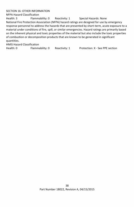
SECTION 16: OTHER INFORMATION NFPA Hazard Classification Health: 3 Flammability: 0 Reactivity: 1 Special Hazards: None National Fire Protection Association (NFPA) hazard ratings are designed for use by emergency response personnel to address the hazards that are presented by short-term, acute exposure to a material under conditions of fire, spill, or similar emergencies. Hazard ratings are primarily based on the inherent physical and toxic properties of the material but also include the toxic properties of combustion or decomposition products that are known to be generated in significant quantities. HMIS Hazard Classification Health: 0 Flammability: 0 Reactivity: 1 Protection: X - See PPE section

39 Part Number 18022, Revision A, 04/15/2015
Returning Fireboy-Xintex Equipment
No product may be returned for credit or repair without a written “Returned Material Authorization” (RMA) form. Purchaser must call or email Fireboy-Xintex 616-735-9380 or [email protected] for a RMA. If due to extenuating circumstances a product is to be returned, after approval it must be received in 100% new/resalable condition. Products stored by the buyer for more than 26 weeks may not be returned for any reason. Maintaining fresh and current inventory is the responsibility of the buyer.
Recharging Fireboy Extinguishers
Fireboy-Xintex cylinders comply with DOT specification 4BW/360 which allows for recharging as long as the extinguisher was not discharged due to a fire and passes visual inspection in accordance with CGA C-6, or a hydrostatic test. Extinguisher cannot be recharged or refilled in the field. Contact manufacturer for details on the recharging process.
40 Part Number 18022, Revision A, 04/15/2015
3 Year Limited Warranty
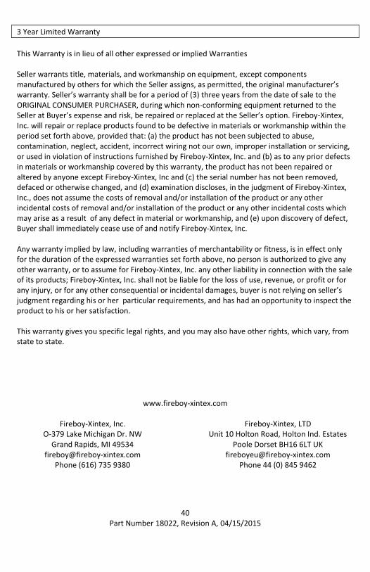
This Warranty is in lieu of all other expressed or implied Warranties Seller warrants title, materials, and workmanship on equipment, except components manufactured by others for which the Seller assigns, as permitted, the original manufacturer’s warranty. Seller’s warranty shall be for a period of (3) three years from the date of sale to the ORIGINAL CONSUMER PURCHASER, during which non-conforming equipment returned to the Seller at Buyer’s expense and risk, be repaired or replaced at the Seller’s option. Fireboy-Xintex, Inc. will repair or replace products found to be defective in materials or workmanship within the period set forth above, provided that: (a) the product has not been subjected to abuse, contamination, neglect, accident, incorrect wiring not our own, improper installation or servicing, or used in violation of instructions furnished by Fireboy-Xintex, Inc. and (b) as to any prior defects in materials or workmanship covered by this warranty, the product has not been repaired or altered by anyone except Fireboy-Xintex, Inc and (c) the serial number has not been removed, defaced or otherwise changed, and (d) examination discloses, in the judgment of Fireboy-Xintex, Inc., does not assume the costs of removal and/or installation of the product or any other incidental costs of removal and/or installation of the product or any other incidental costs which may arise as a result of any defect in material or workmanship, and (e) upon discovery of defect, Buyer shall immediately cease use of and notify Fireboy-Xintex, Inc. Any warranty implied by law, including warranties of merchantability or fitness, is in effect only for the duration of the expressed warranties set forth above, no person is authorized to give any other warranty, or to assume for Fireboy-Xintex, Inc. any other liability in connection with the sale of its products; Fireboy-Xintex, Inc. shall not be liable for the loss of use, revenue, or profit or for any injury, or for any other consequential or incidental damages, buyer is not relying on seller’s judgment regarding his or her particular requirements, and has had an opportunity to inspect the product to his or her satisfaction. This warranty gives you specific legal rights, and you may also have other rights, which vary, from state to state.
www.fireboy-xintex.com
Fireboy-Xintex, Inc. O-379 Lake Michigan Dr. NW
Grand Rapids, MI 49534 [email protected]
Phone (616) 735 9380
Fireboy-Xintex, LTD Unit 10 Holton Road, Holton Ind. Estates
Poole Dorset BH16 6LT UK [email protected]
Phone 44 (0) 845 9462