g l swir c goldeye g/cl - allied vision
TRANSCRIPT
GIGE VISION & CAMERA LINK SWIR CAMERAS
Goldeye G/CL
User Guide
V4.4.1
Allied Vision Technologies GmbH // Taschenweg 2a, 07646 Stadtroda, Germany
2022-Jan-21
Read before use
Read before use
EN - English
SafetyBefore using the camera, read these safety instructions. Observe the warnings at all times. Use the camera only as stated in the Intended use on page 33.
Intended useIntended use of Allied Vision product is the integration into vision systems by professionals. All Allied Vision product is sold in a B2B setting.
Quick links
• Goldeye G/CL cameras at a glance on page 14
• Contact us on page 16
• Contents on page 17
CAUTION
Risk of burns
A camera in operation can reach temperature levels which could cause burns.
CAUTION
Injury by falling cameras or lenses
A falling camera or lens can cause injury.
CAUTION
Risk of cuts by sharp edges of lens mounts
The threads of the lens mount can have sharp edges.
2Goldeye G/CL User Guide V4.4.1
Read before use
DA - Dansk
SikkerhedLæs sikkerhedsanvisningerne, før kameraet bruges. Overhold alle advarsler. Brug kun kameraet som anført i Intended use på side 33.
Tilsigtet brugAllied Vision produktets tilsigtede brug er en indbygning i et visionssystem, udført af fagfolk. Alle Allied Vision produkter sælges i B2B.
FORSIGTIG
Forbrændingsfare
Når kameraet bruges, kan det blive meget varmt og forårsage forbrændinger.
FORSIGTIG
Kvæstelser, hvis kameraet eller linser falder ned
Falder kameraet eller linsen ned, kan dette forårsage kvæstelser.
FORSIGTIG
Fare for snitsår på linsemodulets skarpe kanter
Linsemodulets gevind kan have skarpe kanter.
3Goldeye G/CL User Guide V4.4.1
Read before use
DE - Deutsch
SicherheitBevor Sie die Kamera benutzen, lesen Sie diese Sicherheitshinweise. Beachten Sie diese Hinweise immer. Verwenden Sie die Kamera nur wie beschrieben in Intended use auf Seite 33.
Bestimmungsgemäßer GebrauchAllied Vision Produkte sind bestimmt für die Integration in Bildverarbeitungs- systeme durch Fachpersonal. Alle Allied Vision Produkte werden in einer B2B-Umgebung verkauft.
VORSICHT
Gefahr von Verbrennungen
Im Betrieb kann die Kamera Temperaturen erreichen, die zu Verbrennungen führen.
VORSICHT
Verletzung durch fallende Kameras oder Objektive
Eine fallende Kamera oder ein fallendes Objektiv kann Verletzungen verursachen.
VORSICHT
Schnitte durch scharfkantige Objektivgewinde
Objektivgewinde können scharfe Kanten haben.
4Goldeye G/CL User Guide V4.4.1
Read before use
ES - Español
SeguridadAntes de utilizar la cámara lea estas instrucciones de seguridad. Observe las advertencias en todo momento. Utilice la cámara solo tal y como se estipula en el Intended use en la página 33.
Uso previstoEl uso previsto del producto Allied Vision es la integración en el sistema de visión por parte de profesionales. Todos los productos Allied Vision se venden dentro de una relación B2B.
ATENCIÓN
Riesgo de quemaduras
Una cámara en funcionamiento puede alcanzar temperaturas que podrían provocar quemaduras.
ATENCIÓN
Lesiones en caso de que las cámaras o las lentes se caigan
Si una cámara o una lente se cae puede provocar lesiones.
ATENCIÓN
Riesgo de cortes debido a los bordes afilados del objetivo
Las roscas de los objetivos pueden tener bordes afilados.
5Goldeye G/CL User Guide V4.4.1
Read before use
FI - Suomi
TurvallisuusLue nämä turvallisuusohjeet ennen kameran käyttöä. Noudata varoituksia joka hetki. Käytä kameraa ainoastaan kohdassa Intended use sivulla 33 kuvatulla tavalla.
KäyttötarkoitusAllied Vision -tuotteen käyttötarkoitus on integrointi kuvajärjestelmiin ammattilaisten toimesta. Kaikki Allied Vision -tuotteet myydään B2B-ympäristössä.
HUOMIO
Palovammojen vaara
Käytössä olevan kameran saavuttamat lämpötilatasot voivat aiheuttaa palovammoja.
HUOMIO
Putoavien kameroiden tai linssien aiheuttamat vammat
Putoava kamera tai linssi voi aiheuttaa vammoja.
HUOMIO
Linssien kiinnikkeiden terävien reunojen aiheuttamien viiltovammojen vaara
Linssin kiinnikkeiden kierteiden reunat voivat olla teräviä.
6Goldeye G/CL User Guide V4.4.1
Read before use
FR - Français
SécuritéVeuillez lire ces consignes de sécurité avant d’utiliser la caméra. Respectez continuellement les avertissements. Utilisez la caméra uniquement comme indiqué sous Intended use, page 33.
Utilisation prévueL’utilisation prévue du produit Allied Vision est son intégration dans des systèmes de vision par le soin de professionnels. Tout produit Allied Vision est vendu dans un cadre B2B.
ATTENTION
Risque de brûlures
Une caméra en service peut atteindre des niveaux de température susceptibles d’entraîner des brûlures.
ATTENTION
Blessures en cas de chute de caméras ou d’objectifs
La chute d’une caméra ou d’un objectif peut entraîner des blessures.
ATTENTION
Risque de coupures sur les bords tranchants des montures d’objectif
Les filetages des montures d’objectif peuvent présenter des bords tranchants.
7Goldeye G/CL User Guide V4.4.1
Read before use
IT - Italiano
SicurezzaLeggere queste istruzioni per la sicurezza prima di utilizzare la telecamera. Osservare sempre tutte le avvertenze. Utilizzare la telecamera come descritto alla sezione Intended use a pagina 33.
Uso previstoIl prodotto Allied Vision è concepito per essere integrato in sistemi di monitoraggio in campo professionale. Tutti i prodotti Allied Vision sono venduti in uno scenario B2B.
ATTENZIONE
Pericolo di ustioni
Durante il funzionamento una telecamera può raggiungere temperature elevate che possono essere causa di ustioni.
ATTENZIONE
Lesioni dovute alla caduta di telecamere o lenti
La caduta di una telecamera o di una lente può causare delle lesioni.
ATTENZIONE
Pericolo di tagliarsi sui bordi affilati degli attacchi della lente
I bordi della filettatura dell’attacco della lente possono essere affilati.
8Goldeye G/CL User Guide V4.4.1
Read before use
JA - 日本語
安全性本カメラを使用する前に、この安全の手引きをお読みください。常に、警告事項を守ってください。必ず、Intended use 33 ページの通りに、本カ
メラを使用してください。
用途Allied Vision製品は、専門家が視覚装置に統合することを意図したものです。すべてのAllied Vision製品は、企業間取り引き用に販売されています。
注意
やけどの危険性
作動中のカメラは、やけどを引き起こす温度まで熱くなる恐れがあります。
注意
カメラまたはレンズの落下によるけが
カメラまたはレンズが落下すると、けがをする恐れがあります。
注意
レンズマウントの鋭利な端部で切り傷の危険性
レンズマウントのギザギザの部分が鋭利である可能性があります。
9Goldeye G/CL User Guide V4.4.1
Read before use
NL - Nederlands
VeiligheidLees deze veiligheidsinstructies voordat u de camera gaat gebruiken. Neem deze waarschuwingen altijd in acht. Gebruik de camera uitsluitend, zoals aangegeven in het Intended use op pagina 33.
Beoogd gebruikHet beoogde gebruik van het Allied Vision-product is de integratie in optische systemen door professionals. Alle Allied Vision-producten worden verkocht in de B2B-markt.
VOORZICHTIG
Risico van verbranding
Een camera die gebruikt wordt, kan temperatuurwaarden bereiken die brandwonden kunnen veroorzaken.
VOORZICHTIG
Letsel door vallende camera's of lenzen
Een vallende camera of lens kan letsel veroorzaken.
VOORZICHTIG
Risico van snijwonden door scherpe randen van lensbevestigingen
Het schroefdraad van de lensbevestiging kan scherpe randen hebben.
10Goldeye G/CL User Guide V4.4.1
Read before use
NO - Norsk
SikkerhetLes disse sikkerhetsinstruksene før du bruker kameraet. Følg advarslene til en hver tid. Bruk kun kameraet i samsvar med Intended use på side 33.
Tiltenkt brukDen tiltenkte bruken av Allied Vision-produktet er integrering i visjonssystemer av profesjonelle. Alle Allied Vision-produkter selges i en forretning til forretning-situasjon.
FORSIKTIG
Risiko for brannskader
Et kamera i bruk kan nå temperaturnivåer som kan forårsake brannskader.
FORSIKTIG
Skade ved fallende kameraer eller linser
Et fallende kamera eller en fallende linse kan forårsake skade.
FORSIKTIG
Risiko for kutt fra skarpe kanter på linsefester
Sporene på linsefestet kan ha skarpe kanter.
11Goldeye G/CL User Guide V4.4.1
Read before use
SV - Svenska
SäkerhetLäs igenom säkerhetsinstruktionerna innan du använder kameran. Var hela tiden särskilt uppmärksam på varningarna. Använd enbart kameran på det sätt som anges i Intended use på sida 33.
Avsedd användningDen avsedda användningen av Allied Vision-produkter är integrering i visionssystem av fackmän. Samtliga Allied Vision-produkter säljs i en B2B-miljö.
VARNING
Risk för brännskada
En kamera i drift kan komma upp i temperaturer som kan orsaka brännskador.
VARNING
Risk för skador från fallande kameror eller objektiv
Fallande kameror eller objektiv kan förorsaka skador.
VARNING
Risk för skärsår från vassa kanter på objektivfattningar
Objektivets gängor kan ha vassa kanter.
12Goldeye G/CL User Guide V4.4.1
Read before use
ZH - 简体中文版
安全需知使用本相机前,请阅读本安全说明书。请务必遵守相关警告 和 Intended use
于第 33 页 .
预期用途Allied Vision 产品的预期用途是由专业人士整合到视觉系统中。所有 Allied Vision 的产品均通过 B2B 渠道销售。
注意事项烫伤风险
相机操作过程中温度可能上升并导致烫伤风险。
注意事项相机或者镜头跌落造成伤害
相机或者镜头可能会跌落并造成伤害。
注意事项镜头接口的锐利边缘划伤风险
镜头接口螺纹边缘可能较为锐利。
13Goldeye G/CL User Guide V4.4.1
Goldeye G/CL cameras at a glance
Goldeye G/CL User Guide V4.4.1
This chapter includes:
Overview ............................................................................... 15Scope of delivery................................................................... 15What else do you need? ....................................................... 15
14
Goldeye G/CL cameras at a glance
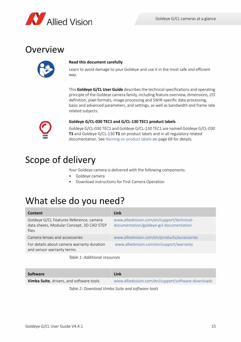
Overview
This Goldeye G/CL User Guide describes the technical specifications and operating principle of the Goldeye camera family, including feature overview, dimensions, I/O definition, pixel formats, image processing and SWIR-specific data processing, basic and advanced parameters, and settings, as well as bandwidth and frame rate related subjects.
Scope of deliveryYour Goldeye camera is delivered with the following components:
• Goldeye camera
• Download instructions for First Camera Operation
What else do you need?
Read this document carefully
Learn to avoid damage to your Goldeye and use it in the most safe and efficient way.
Goldeye G/CL-030 TEC1 and G/CL-130 TEC1 product labels
Goldeye G/CL-030 TEC1 and Goldeye G/CL-130 TEC1 are named Goldeye G/CL-030 T1 and Goldeye G/CL-130 T1 on product labels and in all regulatory related documentation. See Naming on product labels on page 69 for details.
Content Link
Goldeye G/CL Features Reference, camera data sheets, Modular Concept, 3D CAD STEP files
www.alliedvision.com/en/support/technical-documentation/goldeye-gcl-documentation
Camera lenses and accessories www.alliedvision.com/en/products/accessories
For details about camera warranty duration and sensor warranty terms.
www.alliedvision.com/en/support/warranty
Table 1: Additional resources
Software Link
Vimba Suite, drivers, and software tools www.alliedvision.com/en/support/software-downloads
Table 2: Download Vimba Suite and software tools
15Goldeye G/CL User Guide V4.4.1
Contact us
16Goldeye G/CL User Guide V4.4.1
Contact us
Website, emailGeneralwww.alliedvision.com/en/[email protected]
Distribution partnerswww.alliedvision.com/en/avt-locations/avt-distributors
Supportwww.alliedvision.com/en/supportwww.alliedvision.com/en/about-us/contact-us/technical-support-repair-/-rma
OfficesEurope, Middle East, and Africa(Headquarters)
Allied Vision Technologies GmbHTaschenweg 2a07646 Stadtroda, GermanyT// +49 36428 677-0 (Reception)T// +49 36428 677-230 (Sales)F// +49 36428 677-28
Asia-Pacific
China
Allied Vision Technologies(Shanghai) Co., Ltd.2-2109 Hongwell Int. Plaza1602# ZhongShanXi RoadShanghai 200235, ChinaT// +86 21 64861133
Singapore
Allied Vision Technologies Asia Pte. Ltd82 Playfair Rd, #07-02 D'LithiumSingapore 368001T// +65 6634 9027
North, Central, and South America
Canada
Allied Vision Technologies Canada Inc.300 – 4621 Canada WayBurnaby, BC V5G 4X8, CanadaT// +1 604 875 8855
USA
Allied Vision Technologies, Inc.102 Pickering Way - Suite 502Exton, PA 19341, USAToll-free// +1-877-USA-1394T// +1 978 225 2030
Contents
ContentsRead before use 2EN - English . . . . . . . . . . . . . . . . . . . . . . . . . . . . . . . . . . . . . . . . . . . . . . . . . . . . . . . . . . . . . . . . . . . . . . . . . . . . . . . 2DA - Dansk . . . . . . . . . . . . . . . . . . . . . . . . . . . . . . . . . . . . . . . . . . . . . . . . . . . . . . . . . . . . . . . . . . . . . . . . . . . . . . . . 3DE - Deutsch. . . . . . . . . . . . . . . . . . . . . . . . . . . . . . . . . . . . . . . . . . . . . . . . . . . . . . . . . . . . . . . . . . . . . . . . . . . . . . . 4ES - Español . . . . . . . . . . . . . . . . . . . . . . . . . . . . . . . . . . . . . . . . . . . . . . . . . . . . . . . . . . . . . . . . . . . . . . . . . . . . . . . 5FI - Suomi . . . . . . . . . . . . . . . . . . . . . . . . . . . . . . . . . . . . . . . . . . . . . . . . . . . . . . . . . . . . . . . . . . . . . . . . . . . . . . . . . 6FR - Français . . . . . . . . . . . . . . . . . . . . . . . . . . . . . . . . . . . . . . . . . . . . . . . . . . . . . . . . . . . . . . . . . . . . . . . . . . . . . . . 7IT - Italiano . . . . . . . . . . . . . . . . . . . . . . . . . . . . . . . . . . . . . . . . . . . . . . . . . . . . . . . . . . . . . . . . . . . . . . . . . . . . . . . . 8JA -日本語 9NL - Nederlands . . . . . . . . . . . . . . . . . . . . . . . . . . . . . . . . . . . . . . . . . . . . . . . . . . . . . . . . . . . . . . . . . . . . . . . . . . . 10NO - Norsk . . . . . . . . . . . . . . . . . . . . . . . . . . . . . . . . . . . . . . . . . . . . . . . . . . . . . . . . . . . . . . . . . . . . . . . . . . . . . . . 11SV - Svenska . . . . . . . . . . . . . . . . . . . . . . . . . . . . . . . . . . . . . . . . . . . . . . . . . . . . . . . . . . . . . . . . . . . . . . . . . . . . . . 12ZH - 简体中文版 13
Goldeye G/CL cameras at a glance 14Overview . . . . . . . . . . . . . . . . . . . . . . . . . . . . . . . . . . . . . . . . . . . . . . . . . . . . . . . . . . . . . . . . . . . . . . . . . . . . . . . . 15Scope of delivery . . . . . . . . . . . . . . . . . . . . . . . . . . . . . . . . . . . . . . . . . . . . . . . . . . . . . . . . . . . . . . . . . . . . . . . . . . 15What else do you need? . . . . . . . . . . . . . . . . . . . . . . . . . . . . . . . . . . . . . . . . . . . . . . . . . . . . . . . . . . . . . . . . . . . . 15
Contact us 16
Document history and conventions 23Document history . . . . . . . . . . . . . . . . . . . . . . . . . . . . . . . . . . . . . . . . . . . . . . . . . . . . . . . . . . . . . . . . . . . . . . . . . 24Manual conventions . . . . . . . . . . . . . . . . . . . . . . . . . . . . . . . . . . . . . . . . . . . . . . . . . . . . . . . . . . . . . . . . . . . . . . . 27
Typographic styles . . . . . . . . . . . . . . . . . . . . . . . . . . . . . . . . . . . . . . . . . . . . . . . . . . . . . . . . . . . . . . . . . . . . . 27Symbols and notes . . . . . . . . . . . . . . . . . . . . . . . . . . . . . . . . . . . . . . . . . . . . . . . . . . . . . . . . . . . . . . . . . . . . . 27Acronyms and terms. . . . . . . . . . . . . . . . . . . . . . . . . . . . . . . . . . . . . . . . . . . . . . . . . . . . . . . . . . . . . . . . . . . . 28
Compliance, safety, and intended use 30Compliance notifications . . . . . . . . . . . . . . . . . . . . . . . . . . . . . . . . . . . . . . . . . . . . . . . . . . . . . . . . . . . . . . . . . . . 31
For customers in the US . . . . . . . . . . . . . . . . . . . . . . . . . . . . . . . . . . . . . . . . . . . . . . . . . . . . . . . . . . . . . . . . . 31For customers in Canada . . . . . . . . . . . . . . . . . . . . . . . . . . . . . . . . . . . . . . . . . . . . . . . . . . . . . . . . . . . . . . . . 32Pour utilisateurs au Canada . . . . . . . . . . . . . . . . . . . . . . . . . . . . . . . . . . . . . . . . . . . . . . . . . . . . . . . . . . . . . . 32Avoid electromagnetic interferences . . . . . . . . . . . . . . . . . . . . . . . . . . . . . . . . . . . . . . . . . . . . . . . . . . . . . . 32
Intended use . . . . . . . . . . . . . . . . . . . . . . . . . . . . . . . . . . . . . . . . . . . . . . . . . . . . . . . . . . . . . . . . . . . . . . . . . . . . . 33Copyright and trademarks . . . . . . . . . . . . . . . . . . . . . . . . . . . . . . . . . . . . . . . . . . . . . . . . . . . . . . . . . . . . . . . . . . 33Your safety . . . . . . . . . . . . . . . . . . . . . . . . . . . . . . . . . . . . . . . . . . . . . . . . . . . . . . . . . . . . . . . . . . . . . . . . . . . . . . . 34
Handling lens mounts. . . . . . . . . . . . . . . . . . . . . . . . . . . . . . . . . . . . . . . . . . . . . . . . . . . . . . . . . . . . . . . . . . . 34Handling hot cameras. . . . . . . . . . . . . . . . . . . . . . . . . . . . . . . . . . . . . . . . . . . . . . . . . . . . . . . . . . . . . . . . . . . 34Providing optimum heat dissipation . . . . . . . . . . . . . . . . . . . . . . . . . . . . . . . . . . . . . . . . . . . . . . . . . . . . . . . 34Camera mounting . . . . . . . . . . . . . . . . . . . . . . . . . . . . . . . . . . . . . . . . . . . . . . . . . . . . . . . . . . . . . . . . . . . . . . 34
Product safety . . . . . . . . . . . . . . . . . . . . . . . . . . . . . . . . . . . . . . . . . . . . . . . . . . . . . . . . . . . . . . . . . . . . . . . . . . . . 35Electrical connections. . . . . . . . . . . . . . . . . . . . . . . . . . . . . . . . . . . . . . . . . . . . . . . . . . . . . . . . . . . . . . . . . . . 35Optical components . . . . . . . . . . . . . . . . . . . . . . . . . . . . . . . . . . . . . . . . . . . . . . . . . . . . . . . . . . . . . . . . . . . . 36
17Goldeye G/CL User Guide V4.4.1
Contents
Installing the camera (GigE) 37Touching hot cameras. . . . . . . . . . . . . . . . . . . . . . . . . . . . . . . . . . . . . . . . . . . . . . . . . . . . . . . . . . . . . . . . . . . . . . 38Electrostatic discharge . . . . . . . . . . . . . . . . . . . . . . . . . . . . . . . . . . . . . . . . . . . . . . . . . . . . . . . . . . . . . . . . . . . . . 38Mounting the camera . . . . . . . . . . . . . . . . . . . . . . . . . . . . . . . . . . . . . . . . . . . . . . . . . . . . . . . . . . . . . . . . . . . . . . 38
Mounting non-Cool models . . . . . . . . . . . . . . . . . . . . . . . . . . . . . . . . . . . . . . . . . . . . . . . . . . . . . . . . . . . . . . 39Mounting Cool models . . . . . . . . . . . . . . . . . . . . . . . . . . . . . . . . . . . . . . . . . . . . . . . . . . . . . . . . . . . . . . . . . . 39Adapting maximum torque values . . . . . . . . . . . . . . . . . . . . . . . . . . . . . . . . . . . . . . . . . . . . . . . . . . . . . . . . 401/4” -20 UNC mounting thread . . . . . . . . . . . . . . . . . . . . . . . . . . . . . . . . . . . . . . . . . . . . . . . . . . . . . . . . . . . 41
Mounting the lens . . . . . . . . . . . . . . . . . . . . . . . . . . . . . . . . . . . . . . . . . . . . . . . . . . . . . . . . . . . . . . . . . . . . . . . . . 41Configuring the host computer . . . . . . . . . . . . . . . . . . . . . . . . . . . . . . . . . . . . . . . . . . . . . . . . . . . . . . . . . . . . . . 42
Installing the NIC driver . . . . . . . . . . . . . . . . . . . . . . . . . . . . . . . . . . . . . . . . . . . . . . . . . . . . . . . . . . . . . . . . . 43Optional: Modifying NIC IP address . . . . . . . . . . . . . . . . . . . . . . . . . . . . . . . . . . . . . . . . . . . . . . . . . . . . . . . 43Optimizing system performance . . . . . . . . . . . . . . . . . . . . . . . . . . . . . . . . . . . . . . . . . . . . . . . . . . . . . . . . . . 44Enabling jumbo packets . . . . . . . . . . . . . . . . . . . . . . . . . . . . . . . . . . . . . . . . . . . . . . . . . . . . . . . . . . . . . . . . . 44
Connecting your camera. . . . . . . . . . . . . . . . . . . . . . . . . . . . . . . . . . . . . . . . . . . . . . . . . . . . . . . . . . . . . . . . . . . . 45Powering up the camera. . . . . . . . . . . . . . . . . . . . . . . . . . . . . . . . . . . . . . . . . . . . . . . . . . . . . . . . . . . . . . . . . . . . 45
Hardware Selection . . . . . . . . . . . . . . . . . . . . . . . . . . . . . . . . . . . . . . . . . . . . . . . . . . . . . . . . . . . . . . . . . . . . 47Powering the camera via PoE . . . . . . . . . . . . . . . . . . . . . . . . . . . . . . . . . . . . . . . . . . . . . . . . . . . . . . . . . . . . 47
Connecting to the host computer . . . . . . . . . . . . . . . . . . . . . . . . . . . . . . . . . . . . . . . . . . . . . . . . . . . . . . . . . . . . 47Allied Vision software . . . . . . . . . . . . . . . . . . . . . . . . . . . . . . . . . . . . . . . . . . . . . . . . . . . . . . . . . . . . . . . . . . . 48Third-party software. . . . . . . . . . . . . . . . . . . . . . . . . . . . . . . . . . . . . . . . . . . . . . . . . . . . . . . . . . . . . . . . . . . . 48Configuring your camera . . . . . . . . . . . . . . . . . . . . . . . . . . . . . . . . . . . . . . . . . . . . . . . . . . . . . . . . . . . . . . . . 49
Accessories. . . . . . . . . . . . . . . . . . . . . . . . . . . . . . . . . . . . . . . . . . . . . . . . . . . . . . . . . . . . . . . . . . . . . . . . . . . . . . . 50
Installing the camera (CL) 51Touching hot cameras. . . . . . . . . . . . . . . . . . . . . . . . . . . . . . . . . . . . . . . . . . . . . . . . . . . . . . . . . . . . . . . . . . . . . . 52Electrostatic discharge . . . . . . . . . . . . . . . . . . . . . . . . . . . . . . . . . . . . . . . . . . . . . . . . . . . . . . . . . . . . . . . . . . . . . 52Mounting the camera . . . . . . . . . . . . . . . . . . . . . . . . . . . . . . . . . . . . . . . . . . . . . . . . . . . . . . . . . . . . . . . . . . . . . . 52
Mounting non-Cool models . . . . . . . . . . . . . . . . . . . . . . . . . . . . . . . . . . . . . . . . . . . . . . . . . . . . . . . . . . . . . . 53Mounting Cool models . . . . . . . . . . . . . . . . . . . . . . . . . . . . . . . . . . . . . . . . . . . . . . . . . . . . . . . . . . . . . . . . . . 53Adapting maximum torque values . . . . . . . . . . . . . . . . . . . . . . . . . . . . . . . . . . . . . . . . . . . . . . . . . . . . . . . . 541/4” -20 UNC mounting thread . . . . . . . . . . . . . . . . . . . . . . . . . . . . . . . . . . . . . . . . . . . . . . . . . . . . . . . . . . . 55
Mounting the lens . . . . . . . . . . . . . . . . . . . . . . . . . . . . . . . . . . . . . . . . . . . . . . . . . . . . . . . . . . . . . . . . . . . . . . . . . 55Installing hardware and software . . . . . . . . . . . . . . . . . . . . . . . . . . . . . . . . . . . . . . . . . . . . . . . . . . . . . . . . . . . . 56
Frame grabbers . . . . . . . . . . . . . . . . . . . . . . . . . . . . . . . . . . . . . . . . . . . . . . . . . . . . . . . . . . . . . . . . . . . . . . . . 56Installing a frame grabber . . . . . . . . . . . . . . . . . . . . . . . . . . . . . . . . . . . . . . . . . . . . . . . . . . . . . . . . . . . . . . . 56Installing camera software. . . . . . . . . . . . . . . . . . . . . . . . . . . . . . . . . . . . . . . . . . . . . . . . . . . . . . . . . . . . . . . 56
Connecting your camera. . . . . . . . . . . . . . . . . . . . . . . . . . . . . . . . . . . . . . . . . . . . . . . . . . . . . . . . . . . . . . . . . . . . 57Powering up the camera. . . . . . . . . . . . . . . . . . . . . . . . . . . . . . . . . . . . . . . . . . . . . . . . . . . . . . . . . . . . . . . . . . . . 57Connecting to the host computer . . . . . . . . . . . . . . . . . . . . . . . . . . . . . . . . . . . . . . . . . . . . . . . . . . . . . . . . . . . . 58
Allied Vision software . . . . . . . . . . . . . . . . . . . . . . . . . . . . . . . . . . . . . . . . . . . . . . . . . . . . . . . . . . . . . . . . . . . 59Third-party software. . . . . . . . . . . . . . . . . . . . . . . . . . . . . . . . . . . . . . . . . . . . . . . . . . . . . . . . . . . . . . . . . . . . 59Configuring your camera . . . . . . . . . . . . . . . . . . . . . . . . . . . . . . . . . . . . . . . . . . . . . . . . . . . . . . . . . . . . . . . . 60
Camera control and image viewing . . . . . . . . . . . . . . . . . . . . . . . . . . . . . . . . . . . . . . . . . . . . . . . . . . . . . . . . . . . 60Vimba with frame grabber specific viewer. . . . . . . . . . . . . . . . . . . . . . . . . . . . . . . . . . . . . . . . . . . . . . . . . . 60Using a custom application . . . . . . . . . . . . . . . . . . . . . . . . . . . . . . . . . . . . . . . . . . . . . . . . . . . . . . . . . . . . . . 66Using frame grabber transport layer. . . . . . . . . . . . . . . . . . . . . . . . . . . . . . . . . . . . . . . . . . . . . . . . . . . . . . . 66Troubleshooting . . . . . . . . . . . . . . . . . . . . . . . . . . . . . . . . . . . . . . . . . . . . . . . . . . . . . . . . . . . . . . . . . . . . . . . 67
18Goldeye G/CL User Guide V4.4.1
Contents
Specifications 68Model naming . . . . . . . . . . . . . . . . . . . . . . . . . . . . . . . . . . . . . . . . . . . . . . . . . . . . . . . . . . . . . . . . . . . . . . . . . . . . 69
Name affix for temperature control . . . . . . . . . . . . . . . . . . . . . . . . . . . . . . . . . . . . . . . . . . . . . . . . . . . . . . . 69Name affix for housing size . . . . . . . . . . . . . . . . . . . . . . . . . . . . . . . . . . . . . . . . . . . . . . . . . . . . . . . . . . . . . . 70
Applied standards . . . . . . . . . . . . . . . . . . . . . . . . . . . . . . . . . . . . . . . . . . . . . . . . . . . . . . . . . . . . . . . . . . . . . . . . . 71Camera Link standard (CL models) . . . . . . . . . . . . . . . . . . . . . . . . . . . . . . . . . . . . . . . . . . . . . . . . . . . . . . . . 71GenICam . . . . . . . . . . . . . . . . . . . . . . . . . . . . . . . . . . . . . . . . . . . . . . . . . . . . . . . . . . . . . . . . . . . . . . . . . . . . . 71GenCP . . . . . . . . . . . . . . . . . . . . . . . . . . . . . . . . . . . . . . . . . . . . . . . . . . . . . . . . . . . . . . . . . . . . . . . . . . . . . . . 71GigE Vision (GigE models) . . . . . . . . . . . . . . . . . . . . . . . . . . . . . . . . . . . . . . . . . . . . . . . . . . . . . . . . . . . . . . . 71IP class . . . . . . . . . . . . . . . . . . . . . . . . . . . . . . . . . . . . . . . . . . . . . . . . . . . . . . . . . . . . . . . . . . . . . . . . . . . . . . . 71Shock and vibration . . . . . . . . . . . . . . . . . . . . . . . . . . . . . . . . . . . . . . . . . . . . . . . . . . . . . . . . . . . . . . . . . . . . 72
Maximum and ROI frame rates . . . . . . . . . . . . . . . . . . . . . . . . . . . . . . . . . . . . . . . . . . . . . . . . . . . . . . . . . . . . . . 74Frame rates and temperature control . . . . . . . . . . . . . . . . . . . . . . . . . . . . . . . . . . . . . . . . . . . . . . . . . . . . . 74
Specifications (GigE models) . . . . . . . . . . . . . . . . . . . . . . . . . . . . . . . . . . . . . . . . . . . . . . . . . . . . . . . . . . . . . . . . 75Goldeye G-008 TEC1. . . . . . . . . . . . . . . . . . . . . . . . . . . . . . . . . . . . . . . . . . . . . . . . . . . . . . . . . . . . . . . . . . . . 75Goldeye G-008 Cool TEC1 . . . . . . . . . . . . . . . . . . . . . . . . . . . . . . . . . . . . . . . . . . . . . . . . . . . . . . . . . . . . . . . 79Goldeye G-030 TEC1. . . . . . . . . . . . . . . . . . . . . . . . . . . . . . . . . . . . . . . . . . . . . . . . . . . . . . . . . . . . . . . . . . . . 83Goldeye G-032 TEC1. . . . . . . . . . . . . . . . . . . . . . . . . . . . . . . . . . . . . . . . . . . . . . . . . . . . . . . . . . . . . . . . . . . . 87Goldeye G-032 Cool TEC2 . . . . . . . . . . . . . . . . . . . . . . . . . . . . . . . . . . . . . . . . . . . . . . . . . . . . . . . . . . . . . . . 91Goldeye G-033 TEC1. . . . . . . . . . . . . . . . . . . . . . . . . . . . . . . . . . . . . . . . . . . . . . . . . . . . . . . . . . . . . . . . . . . . 95Goldeye G-033 TECless. . . . . . . . . . . . . . . . . . . . . . . . . . . . . . . . . . . . . . . . . . . . . . . . . . . . . . . . . . . . . . . . . . 99Goldeye G-034 TEC1. . . . . . . . . . . . . . . . . . . . . . . . . . . . . . . . . . . . . . . . . . . . . . . . . . . . . . . . . . . . . . . . . . . 103Goldeye G-130 TEC1. . . . . . . . . . . . . . . . . . . . . . . . . . . . . . . . . . . . . . . . . . . . . . . . . . . . . . . . . . . . . . . . . . . 107
Specifications (CL models) . . . . . . . . . . . . . . . . . . . . . . . . . . . . . . . . . . . . . . . . . . . . . . . . . . . . . . . . . . . . . . . . . 112Goldeye CL-008 TEC1 . . . . . . . . . . . . . . . . . . . . . . . . . . . . . . . . . . . . . . . . . . . . . . . . . . . . . . . . . . . . . . . . . .112Goldeye CL-008 Cool TEC1. . . . . . . . . . . . . . . . . . . . . . . . . . . . . . . . . . . . . . . . . . . . . . . . . . . . . . . . . . . . . .117Goldeye CL-030 TEC1 . . . . . . . . . . . . . . . . . . . . . . . . . . . . . . . . . . . . . . . . . . . . . . . . . . . . . . . . . . . . . . . . . .122Goldeye CL-032 TEC1 . . . . . . . . . . . . . . . . . . . . . . . . . . . . . . . . . . . . . . . . . . . . . . . . . . . . . . . . . . . . . . . . . .127Goldeye CL-032 Cool TEC2. . . . . . . . . . . . . . . . . . . . . . . . . . . . . . . . . . . . . . . . . . . . . . . . . . . . . . . . . . . . . .132Goldeye CL-033 TEC1 . . . . . . . . . . . . . . . . . . . . . . . . . . . . . . . . . . . . . . . . . . . . . . . . . . . . . . . . . . . . . . . . . .137Goldeye CL-033 TECless . . . . . . . . . . . . . . . . . . . . . . . . . . . . . . . . . . . . . . . . . . . . . . . . . . . . . . . . . . . . . . . . 142Goldeye CL-034 TEC1 . . . . . . . . . . . . . . . . . . . . . . . . . . . . . . . . . . . . . . . . . . . . . . . . . . . . . . . . . . . . . . . . . .147Goldeye CL-130 TEC1 . . . . . . . . . . . . . . . . . . . . . . . . . . . . . . . . . . . . . . . . . . . . . . . . . . . . . . . . . . . . . . . . . .152
Camera dimensions (GigE models) . . . . . . . . . . . . . . . . . . . . . . . . . . . . . . . . . . . . . . . . . . . . . . . . . . . . . . . . . . 157Technical drawings by model. . . . . . . . . . . . . . . . . . . . . . . . . . . . . . . . . . . . . . . . . . . . . . . . . . . . . . . . . . . . 157Goldeye G with fixed C-Mount . . . . . . . . . . . . . . . . . . . . . . . . . . . . . . . . . . . . . . . . . . . . . . . . . . . . . . . . . . 158Goldeye G with C-Mount adapter . . . . . . . . . . . . . . . . . . . . . . . . . . . . . . . . . . . . . . . . . . . . . . . . . . . . . . . . 159Goldeye G with F-Mount adapter . . . . . . . . . . . . . . . . . . . . . . . . . . . . . . . . . . . . . . . . . . . . . . . . . . . . . . . .160Goldeye G with M42-Mount adapter . . . . . . . . . . . . . . . . . . . . . . . . . . . . . . . . . . . . . . . . . . . . . . . . . . . . . 161Goldeye G-034 TEC1 with C-Mount adapter . . . . . . . . . . . . . . . . . . . . . . . . . . . . . . . . . . . . . . . . . . . . . . .162Goldeye G-034 TEC1 with F-Mount adapter . . . . . . . . . . . . . . . . . . . . . . . . . . . . . . . . . . . . . . . . . . . . . . . 163Goldeye G-034 TEC1 with M42-Mount adapter . . . . . . . . . . . . . . . . . . . . . . . . . . . . . . . . . . . . . . . . . . . . 164Goldeye G Cool with C-Mount adapter. . . . . . . . . . . . . . . . . . . . . . . . . . . . . . . . . . . . . . . . . . . . . . . . . . . . 165Goldeye G Cool with F-Mount adapter . . . . . . . . . . . . . . . . . . . . . . . . . . . . . . . . . . . . . . . . . . . . . . . . . . .166Goldeye G Cool with M42-Mount adapter . . . . . . . . . . . . . . . . . . . . . . . . . . . . . . . . . . . . . . . . . . . . . . . . .167
Camera dimensions (CL models) . . . . . . . . . . . . . . . . . . . . . . . . . . . . . . . . . . . . . . . . . . . . . . . . . . . . . . . . . . . .168Technical drawings by model. . . . . . . . . . . . . . . . . . . . . . . . . . . . . . . . . . . . . . . . . . . . . . . . . . . . . . . . . . . . 168You can find drawings for the corresponding models on pages: . . . . . . . . . . . . . . . . . . . . . . . . . . . . . . .168
19Goldeye G/CL User Guide V4.4.1
Contents
Goldeye CL with fixed C-Mount. . . . . . . . . . . . . . . . . . . . . . . . . . . . . . . . . . . . . . . . . . . . . . . . . . . . . . . . . .169Goldeye CL with C-Mount adapter . . . . . . . . . . . . . . . . . . . . . . . . . . . . . . . . . . . . . . . . . . . . . . . . . . . . . . . 170Goldeye CL with F-Mount adapter . . . . . . . . . . . . . . . . . . . . . . . . . . . . . . . . . . . . . . . . . . . . . . . . . . . . . . .171Goldeye CL with M42-Mount adapter . . . . . . . . . . . . . . . . . . . . . . . . . . . . . . . . . . . . . . . . . . . . . . . . . . . .172Goldeye CL-034 TEC1 with C-Mount adapter . . . . . . . . . . . . . . . . . . . . . . . . . . . . . . . . . . . . . . . . . . . . . . 173Goldeye CL-034 TEC1 with F-Mount adapter. . . . . . . . . . . . . . . . . . . . . . . . . . . . . . . . . . . . . . . . . . . . . . . 174Goldeye CL-034 TEC1 with M42-Mount adapter . . . . . . . . . . . . . . . . . . . . . . . . . . . . . . . . . . . . . . . . . . .175Goldeye CL Cool with C-Mount adapter . . . . . . . . . . . . . . . . . . . . . . . . . . . . . . . . . . . . . . . . . . . . . . . . . . . 176
Sensor position accuracy . . . . . . . . . . . . . . . . . . . . . . . . . . . . . . . . . . . . . . . . . . . . . . . . . . . . . . . . . . . . . . . . . . 177
Accessories 178Electrical connections . . . . . . . . . . . . . . . . . . . . . . . . . . . . . . . . . . . . . . . . . . . . . . . . . . . . . . . . . . . . . . . . . . . . .179Power supplies. . . . . . . . . . . . . . . . . . . . . . . . . . . . . . . . . . . . . . . . . . . . . . . . . . . . . . . . . . . . . . . . . . . . . . . . . . . 179
Goldeye G/CL models . . . . . . . . . . . . . . . . . . . . . . . . . . . . . . . . . . . . . . . . . . . . . . . . . . . . . . . . . . . . . . . . . .179Goldeye G/CL Cool models. . . . . . . . . . . . . . . . . . . . . . . . . . . . . . . . . . . . . . . . . . . . . . . . . . . . . . . . . . . . . .179AC supply cables for power supplies . . . . . . . . . . . . . . . . . . . . . . . . . . . . . . . . . . . . . . . . . . . . . . . . . . . . . 180Hirose 4-pin power cables for Goldeye Cool models . . . . . . . . . . . . . . . . . . . . . . . . . . . . . . . . . . . . . . . .180
Ethernet adapters . . . . . . . . . . . . . . . . . . . . . . . . . . . . . . . . . . . . . . . . . . . . . . . . . . . . . . . . . . . . . . . . . . . . . . . .181Camera Link cables . . . . . . . . . . . . . . . . . . . . . . . . . . . . . . . . . . . . . . . . . . . . . . . . . . . . . . . . . . . . . . . . . . . . . . . 181
MDR-26 to SDR-26 cables . . . . . . . . . . . . . . . . . . . . . . . . . . . . . . . . . . . . . . . . . . . . . . . . . . . . . . . . . . . . . . 181SDR-26 to SDR-26 cables . . . . . . . . . . . . . . . . . . . . . . . . . . . . . . . . . . . . . . . . . . . . . . . . . . . . . . . . . . . . . . .182
Hirose 12-pin I/O connectors and cables . . . . . . . . . . . . . . . . . . . . . . . . . . . . . . . . . . . . . . . . . . . . . . . . . . . . . 182Lens mount adapters . . . . . . . . . . . . . . . . . . . . . . . . . . . . . . . . . . . . . . . . . . . . . . . . . . . . . . . . . . . . . . . . . . . . . 183Optical filters and accessories . . . . . . . . . . . . . . . . . . . . . . . . . . . . . . . . . . . . . . . . . . . . . . . . . . . . . . . . . . . . . . 184
Filter mounting sets . . . . . . . . . . . . . . . . . . . . . . . . . . . . . . . . . . . . . . . . . . . . . . . . . . . . . . . . . . . . . . . . . . .184Bandpass filter 1450 nm (water filter) . . . . . . . . . . . . . . . . . . . . . . . . . . . . . . . . . . . . . . . . . . . . . . . . . . . . 184Filters for cameras with fixed C-Mount . . . . . . . . . . . . . . . . . . . . . . . . . . . . . . . . . . . . . . . . . . . . . . . . . . 185
Heat sink set. . . . . . . . . . . . . . . . . . . . . . . . . . . . . . . . . . . . . . . . . . . . . . . . . . . . . . . . . . . . . . . . . . . . . . . . . . . . .186
Using lens mounts and filters 187Camera models and lens mounts. . . . . . . . . . . . . . . . . . . . . . . . . . . . . . . . . . . . . . . . . . . . . . . . . . . . . . . . . . . . 188Changing the lens adapter . . . . . . . . . . . . . . . . . . . . . . . . . . . . . . . . . . . . . . . . . . . . . . . . . . . . . . . . . . . . . . . . . 188C-Mount lens adapter . . . . . . . . . . . . . . . . . . . . . . . . . . . . . . . . . . . . . . . . . . . . . . . . . . . . . . . . . . . . . . . . . . . . .189
Specifications of the C-Mount adapter. . . . . . . . . . . . . . . . . . . . . . . . . . . . . . . . . . . . . . . . . . . . . . . . . . . . 189Changing the filter in the C-Mount adapter . . . . . . . . . . . . . . . . . . . . . . . . . . . . . . . . . . . . . . . . . . . . . . . . 190
F-Mount lens adapter . . . . . . . . . . . . . . . . . . . . . . . . . . . . . . . . . . . . . . . . . . . . . . . . . . . . . . . . . . . . . . . . . . . . .192Specifications of the F-Mount adapter . . . . . . . . . . . . . . . . . . . . . . . . . . . . . . . . . . . . . . . . . . . . . . . . . . .192Changing the filter in the F-Mount adapter . . . . . . . . . . . . . . . . . . . . . . . . . . . . . . . . . . . . . . . . . . . . . . . . 193
M42-Mount lens adapter . . . . . . . . . . . . . . . . . . . . . . . . . . . . . . . . . . . . . . . . . . . . . . . . . . . . . . . . . . . . . . . . . .194Specifications of the M42-Mount adapter . . . . . . . . . . . . . . . . . . . . . . . . . . . . . . . . . . . . . . . . . . . . . . . .195Changing the filter in the M42-Mount adapter . . . . . . . . . . . . . . . . . . . . . . . . . . . . . . . . . . . . . . . . . . . . .195
Adjusting the C-Mount . . . . . . . . . . . . . . . . . . . . . . . . . . . . . . . . . . . . . . . . . . . . . . . . . . . . . . . . . . . . . . . . . . . .197Preconditions . . . . . . . . . . . . . . . . . . . . . . . . . . . . . . . . . . . . . . . . . . . . . . . . . . . . . . . . . . . . . . . . . . . . . . . .197Instructions . . . . . . . . . . . . . . . . . . . . . . . . . . . . . . . . . . . . . . . . . . . . . . . . . . . . . . . . . . . . . . . . . . . . . . . . . . 198
Replacing filters on cameras with fixed C-Mount. . . . . . . . . . . . . . . . . . . . . . . . . . . . . . . . . . . . . . . . . . . . . . . 198Preconditions . . . . . . . . . . . . . . . . . . . . . . . . . . . . . . . . . . . . . . . . . . . . . . . . . . . . . . . . . . . . . . . . . . . . . . . .198Inserting filters . . . . . . . . . . . . . . . . . . . . . . . . . . . . . . . . . . . . . . . . . . . . . . . . . . . . . . . . . . . . . . . . . . . . . . . 199Removing filters . . . . . . . . . . . . . . . . . . . . . . . . . . . . . . . . . . . . . . . . . . . . . . . . . . . . . . . . . . . . . . . . . . . . . . 199
20Goldeye G/CL User Guide V4.4.1
Contents
Filter specifications . . . . . . . . . . . . . . . . . . . . . . . . . . . . . . . . . . . . . . . . . . . . . . . . . . . . . . . . . . . . . . . . . . . . . . . 200General terms explained . . . . . . . . . . . . . . . . . . . . . . . . . . . . . . . . . . . . . . . . . . . . . . . . . . . . . . . . . . . . . . .200Bandpass filters . . . . . . . . . . . . . . . . . . . . . . . . . . . . . . . . . . . . . . . . . . . . . . . . . . . . . . . . . . . . . . . . . . . . . . . 200
Camera interfaces 204GigE port, back panel, and status LEDs (GigE) . . . . . . . . . . . . . . . . . . . . . . . . . . . . . . . . . . . . . . . . . . . . . . . . . 205
Gigabit Ethernet port . . . . . . . . . . . . . . . . . . . . . . . . . . . . . . . . . . . . . . . . . . . . . . . . . . . . . . . . . . . . . . . . . . 205Back panel . . . . . . . . . . . . . . . . . . . . . . . . . . . . . . . . . . . . . . . . . . . . . . . . . . . . . . . . . . . . . . . . . . . . . . . . . . . 205GigE status LEDs . . . . . . . . . . . . . . . . . . . . . . . . . . . . . . . . . . . . . . . . . . . . . . . . . . . . . . . . . . . . . . . . . . . . . . 206
CL port, back panel, and status LED (CL) . . . . . . . . . . . . . . . . . . . . . . . . . . . . . . . . . . . . . . . . . . . . . . . . . . . . . . 207Camera Link port. . . . . . . . . . . . . . . . . . . . . . . . . . . . . . . . . . . . . . . . . . . . . . . . . . . . . . . . . . . . . . . . . . . . . .207Back panel . . . . . . . . . . . . . . . . . . . . . . . . . . . . . . . . . . . . . . . . . . . . . . . . . . . . . . . . . . . . . . . . . . . . . . . .207Camera Link status LED . . . . . . . . . . . . . . . . . . . . . . . . . . . . . . . . . . . . . . . . . . . . . . . . . . . . . . . . . . . . . . 208
Power supply (GigE and CL models) . . . . . . . . . . . . . . . . . . . . . . . . . . . . . . . . . . . . . . . . . . . . . . . . . . . . . . . . . 209Power supply via Hirose connector. . . . . . . . . . . . . . . . . . . . . . . . . . . . . . . . . . . . . . . . . . . . . . . . . . . . . . . 210Power supply via Gigabit Ethernet (Goldeye G only). . . . . . . . . . . . . . . . . . . . . . . . . . . . . . . . . . . . . . . . .210
I/O description (GigE and CL models) . . . . . . . . . . . . . . . . . . . . . . . . . . . . . . . . . . . . . . . . . . . . . . . . . . . . . . . .211I/O connectors and pin assignment . . . . . . . . . . . . . . . . . . . . . . . . . . . . . . . . . . . . . . . . . . . . . . . . . . . . . . 211I/O definitions . . . . . . . . . . . . . . . . . . . . . . . . . . . . . . . . . . . . . . . . . . . . . . . . . . . . . . . . . . . . . . . . . . . . . . . . 215
Frame grabber requirements (CL) . . . . . . . . . . . . . . . . . . . . . . . . . . . . . . . . . . . . . . . . . . . . . . . . . . . . . . . . . . . 223Timing (CL) . . . . . . . . . . . . . . . . . . . . . . . . . . . . . . . . . . . . . . . . . . . . . . . . . . . . . . . . . . . . . . . . . . . . . . . . . . . . . .224
Changing the clock frequency . . . . . . . . . . . . . . . . . . . . . . . . . . . . . . . . . . . . . . . . . . . . . . . . . . . . . . . . . . .224Adjusting the gaps . . . . . . . . . . . . . . . . . . . . . . . . . . . . . . . . . . . . . . . . . . . . . . . . . . . . . . . . . . . . . . . . . . . .225Sequential overview . . . . . . . . . . . . . . . . . . . . . . . . . . . . . . . . . . . . . . . . . . . . . . . . . . . . . . . . . . . . . . . . . . . 226
Starting the acquisition automatically (CL) . . . . . . . . . . . . . . . . . . . . . . . . . . . . . . . . . . . . . . . . . . . . . . . . . . . . 228
Triggering 229Trigger timing diagram . . . . . . . . . . . . . . . . . . . . . . . . . . . . . . . . . . . . . . . . . . . . . . . . . . . . . . . . . . . . . . . . . . . .230
Trigger definitions. . . . . . . . . . . . . . . . . . . . . . . . . . . . . . . . . . . . . . . . . . . . . . . . . . . . . . . . . . . . . . . . . . . . .230Trigger rules . . . . . . . . . . . . . . . . . . . . . . . . . . . . . . . . . . . . . . . . . . . . . . . . . . . . . . . . . . . . . . . . . . . . . . . . . . . . .231
Triggering during the Idle state . . . . . . . . . . . . . . . . . . . . . . . . . . . . . . . . . . . . . . . . . . . . . . . . . . . . . . . . . .231Triggering during the readout state . . . . . . . . . . . . . . . . . . . . . . . . . . . . . . . . . . . . . . . . . . . . . . . . . . . . . . 231
Image data flow 232Image data flow . . . . . . . . . . . . . . . . . . . . . . . . . . . . . . . . . . . . . . . . . . . . . . . . . . . . . . . . . . . . . . . . . . . . . . . . . .233Image corrections . . . . . . . . . . . . . . . . . . . . . . . . . . . . . . . . . . . . . . . . . . . . . . . . . . . . . . . . . . . . . . . . . . . . . . . .234
Determination and storage of correction data . . . . . . . . . . . . . . . . . . . . . . . . . . . . . . . . . . . . . . . . . . . . . 234Non-uniformity correction . . . . . . . . . . . . . . . . . . . . . . . . . . . . . . . . . . . . . . . . . . . . . . . . . . . . . . . . . . . . . .234Background correction . . . . . . . . . . . . . . . . . . . . . . . . . . . . . . . . . . . . . . . . . . . . . . . . . . . . . . . . . . . . . . . . .235Defect pixel correction . . . . . . . . . . . . . . . . . . . . . . . . . . . . . . . . . . . . . . . . . . . . . . . . . . . . . . . . . . . . . . . . .235
Image processing. . . . . . . . . . . . . . . . . . . . . . . . . . . . . . . . . . . . . . . . . . . . . . . . . . . . . . . . . . . . . . . . . . . . . . . . .236Black level . . . . . . . . . . . . . . . . . . . . . . . . . . . . . . . . . . . . . . . . . . . . . . . . . . . . . . . . . . . . . . . . . . . . . . . . . . . 236Gain . . . . . . . . . . . . . . . . . . . . . . . . . . . . . . . . . . . . . . . . . . . . . . . . . . . . . . . . . . . . . . . . . . . . . . . . . . . . . . . .236Look-up table . . . . . . . . . . . . . . . . . . . . . . . . . . . . . . . . . . . . . . . . . . . . . . . . . . . . . . . . . . . . . . . . . . . . . . . .236Binning . . . . . . . . . . . . . . . . . . . . . . . . . . . . . . . . . . . . . . . . . . . . . . . . . . . . . . . . . . . . . . . . . . . . . . . . . . . . . .237Decimation . . . . . . . . . . . . . . . . . . . . . . . . . . . . . . . . . . . . . . . . . . . . . . . . . . . . . . . . . . . . . . . . . . . . . . . . . . 237
Automatic image control . . . . . . . . . . . . . . . . . . . . . . . . . . . . . . . . . . . . . . . . . . . . . . . . . . . . . . . . . . . . . . . . . . 238Definitions . . . . . . . . . . . . . . . . . . . . . . . . . . . . . . . . . . . . . . . . . . . . . . . . . . . . . . . . . . . . . . . . . . . . . . . . . . . 238
21Goldeye G/CL User Guide V4.4.1
Contents
Automatic exposure control . . . . . . . . . . . . . . . . . . . . . . . . . . . . . . . . . . . . . . . . . . . . . . . . . . . . . . . . . . . .241Contrast control . . . . . . . . . . . . . . . . . . . . . . . . . . . . . . . . . . . . . . . . . . . . . . . . . . . . . . . . . . . . . . . . . . . . . . 243
Other image controls . . . . . . . . . . . . . . . . . . . . . . . . . . . . . . . . . . . . . . . . . . . . . . . . . . . . . . . . . . . . . . . . . . . . . 245Frame memory . . . . . . . . . . . . . . . . . . . . . . . . . . . . . . . . . . . . . . . . . . . . . . . . . . . . . . . . . . . . . . . . . . . . . . . 245Trigger-induced distortion correction. . . . . . . . . . . . . . . . . . . . . . . . . . . . . . . . . . . . . . . . . . . . . . . . . . . . .245
Value changes by feature interdependencies . . . . . . . . . . . . . . . . . . . . . . . . . . . . . . . . . . . . . . . . . . . . . . . . . 247
Temperature control 248Influence of temperature on the sensor . . . . . . . . . . . . . . . . . . . . . . . . . . . . . . . . . . . . . . . . . . . . . . . . . . . . . . 249Control of the sensor temperature . . . . . . . . . . . . . . . . . . . . . . . . . . . . . . . . . . . . . . . . . . . . . . . . . . . . . . . . . . 250
Warm-up period . . . . . . . . . . . . . . . . . . . . . . . . . . . . . . . . . . . . . . . . . . . . . . . . . . . . . . . . . . . . . . . . . . . . . .250Temperature stabilization and active cooling . . . . . . . . . . . . . . . . . . . . . . . . . . . . . . . . . . . . . . . . . . . . . . 250Passive camera cooling. . . . . . . . . . . . . . . . . . . . . . . . . . . . . . . . . . . . . . . . . . . . . . . . . . . . . . . . . . . . . . . . .251Additional heating for G/CL-008, G/CL-x30 . . . . . . . . . . . . . . . . . . . . . . . . . . . . . . . . . . . . . . . . . . . . . . . .251
Neutralization of the temperature influence . . . . . . . . . . . . . . . . . . . . . . . . . . . . . . . . . . . . . . . . . . . . . . . . . . 253Temperature setpoints. . . . . . . . . . . . . . . . . . . . . . . . . . . . . . . . . . . . . . . . . . . . . . . . . . . . . . . . . . . . . . . . .253Switching temperature setpoints . . . . . . . . . . . . . . . . . . . . . . . . . . . . . . . . . . . . . . . . . . . . . . . . . . . . . . . .255Temperature setpoint settling time . . . . . . . . . . . . . . . . . . . . . . . . . . . . . . . . . . . . . . . . . . . . . . . . . . . . . . 258Operational statuses. . . . . . . . . . . . . . . . . . . . . . . . . . . . . . . . . . . . . . . . . . . . . . . . . . . . . . . . . . . . . . . . . . . 261Features for temperature control . . . . . . . . . . . . . . . . . . . . . . . . . . . . . . . . . . . . . . . . . . . . . . . . . . . . . . . . 262
Firmware update 263Firmware loader application . . . . . . . . . . . . . . . . . . . . . . . . . . . . . . . . . . . . . . . . . . . . . . . . . . . . . . . . . . . . . . .264
How to obtain the latest firmware version. . . . . . . . . . . . . . . . . . . . . . . . . . . . . . . . . . . . . . . . . . . . . . . . .264
Cleaning optical components 265Avoiding the necessity of camera cleaning . . . . . . . . . . . . . . . . . . . . . . . . . . . . . . . . . . . . . . . . . . . . . . . . . . . . 266Identifying contaminations. . . . . . . . . . . . . . . . . . . . . . . . . . . . . . . . . . . . . . . . . . . . . . . . . . . . . . . . . . . . . . . . .266
Where is the contamination? — Locating contaminations. . . . . . . . . . . . . . . . . . . . . . . . . . . . . . . . . . . . 267Removing optical filters . . . . . . . . . . . . . . . . . . . . . . . . . . . . . . . . . . . . . . . . . . . . . . . . . . . . . . . . . . . . . . . . . . . 267Cleaning instructions. . . . . . . . . . . . . . . . . . . . . . . . . . . . . . . . . . . . . . . . . . . . . . . . . . . . . . . . . . . . . . . . . . . . . .268
Use of compressed air . . . . . . . . . . . . . . . . . . . . . . . . . . . . . . . . . . . . . . . . . . . . . . . . . . . . . . . . . . . . . . . . 270
Index 271
22Goldeye G/CL User Guide V4.4.1
Document history and conventions
Goldeye G/CL User Guide V4.4.1
This chapter includes:
Document history ................................................................. 24Manual conventions.............................................................. 27
23
Document history and conventions
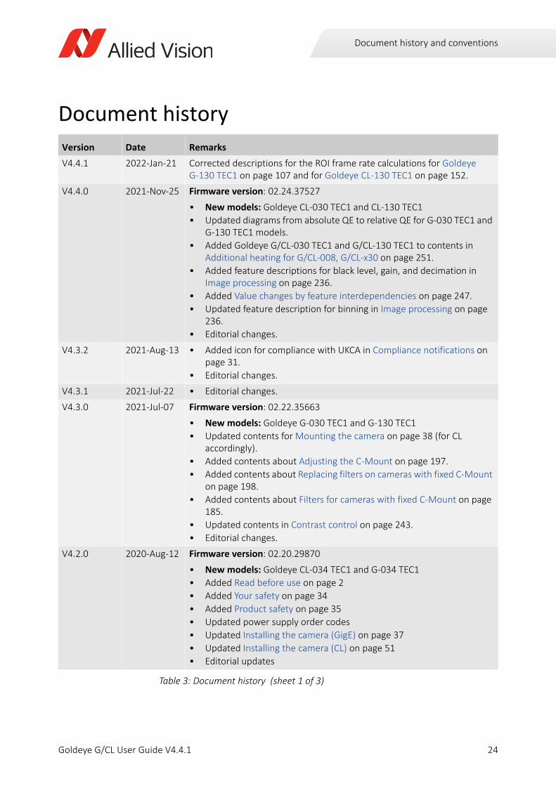
Document history
Version Date Remarks
V4.4.1 2022-Jan-21 Corrected descriptions for the ROI frame rate calculations for Goldeye G-130 TEC1 on page 107 and for Goldeye CL-130 TEC1 on page 152.
V4.4.0 2021-Nov-25 Firmware version: 02.24.37527
• New models: Goldeye CL-030 TEC1 and CL-130 TEC1
• Updated diagrams from absolute QE to relative QE for G-030 TEC1 and G-130 TEC1 models.
• Added Goldeye G/CL-030 TEC1 and G/CL-130 TEC1 to contents in Additional heating for G/CL-008, G/CL-x30 on page 251.
• Added feature descriptions for black level, gain, and decimation in Image processing on page 236.
• Added Value changes by feature interdependencies on page 247.
• Updated feature description for binning in Image processing on page 236.
• Editorial changes.
V4.3.2 2021-Aug-13 • Added icon for compliance with UKCA in Compliance notifications on page 31.
• Editorial changes.
V4.3.1 2021-Jul-22 • Editorial changes.
V4.3.0 2021-Jul-07 Firmware version: 02.22.35663
• New models: Goldeye G-030 TEC1 and G-130 TEC1
• Updated contents for Mounting the camera on page 38 (for CL accordingly).
• Added contents about Adjusting the C-Mount on page 197.
• Added contents about Replacing filters on cameras with fixed C-Mount on page 198.
• Added contents about Filters for cameras with fixed C-Mount on page 185.
• Updated contents in Contrast control on page 243.
• Editorial changes.
V4.2.0 2020-Aug-12 Firmware version: 02.20.29870
• New models: Goldeye CL-034 TEC1 and G-034 TEC1
• Added Read before use on page 2
• Added Your safety on page 34
• Added Product safety on page 35
• Updated power supply order codes
• Updated Installing the camera (GigE) on page 37
• Updated Installing the camera (CL) on page 51
• Editorial updates
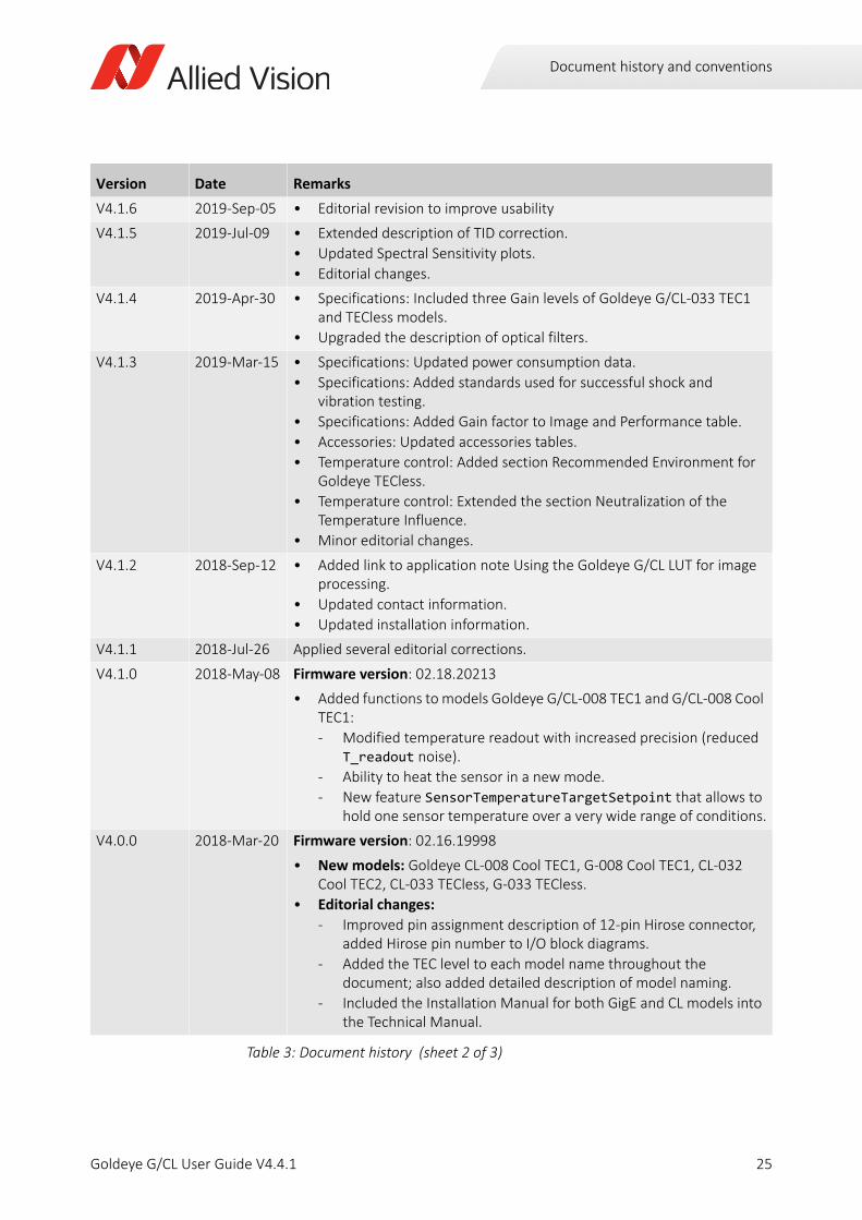
Table 3: Document history (sheet 1 of 3)
24Goldeye G/CL User Guide V4.4.1
Document history and conventions
V4.1.6 2019-Sep-05 • Editorial revision to improve usability
V4.1.5 2019-Jul-09 • Extended description of TID correction.
• Updated Spectral Sensitivity plots.
• Editorial changes.
V4.1.4 2019-Apr-30 • Specifications: Included three Gain levels of Goldeye G/CL-033 TEC1 and TECless models.
• Upgraded the description of optical filters.
V4.1.3 2019-Mar-15 • Specifications: Updated power consumption data.
• Specifications: Added standards used for successful shock and vibration testing.
• Specifications: Added Gain factor to Image and Performance table.
• Accessories: Updated accessories tables.
• Temperature control: Added section Recommended Environment for Goldeye TECless.
• Temperature control: Extended the section Neutralization of the Temperature Influence.
• Minor editorial changes.
V4.1.2 2018-Sep-12 • Added link to application note Using the Goldeye G/CL LUT for image processing.
• Updated contact information.
• Updated installation information.
V4.1.1 2018-Jul-26 Applied several editorial corrections.
V4.1.0 2018-May-08 Firmware version: 02.18.20213
• Added functions to models Goldeye G/CL-008 TEC1 and G/CL-008 Cool TEC1:
- Modified temperature readout with increased precision (reduced T_readout noise).
- Ability to heat the sensor in a new mode.
- New feature SensorTemperatureTargetSetpoint that allows to hold one sensor temperature over a very wide range of conditions.
V4.0.0 2018-Mar-20 Firmware version: 02.16.19998
• New models: Goldeye CL-008 Cool TEC1, G-008 Cool TEC1, CL-032 Cool TEC2, CL-033 TECless, G-033 TECless.
• Editorial changes:
- Improved pin assignment description of 12-pin Hirose connector, added Hirose pin number to I/O block diagrams.
- Added the TEC level to each model name throughout the document; also added detailed description of model naming.
- Included the Installation Manual for both GigE and CL models into the Technical Manual.
Version Date Remarks
Table 3: Document history (sheet 2 of 3)
25Goldeye G/CL User Guide V4.4.1
Document history and conventions
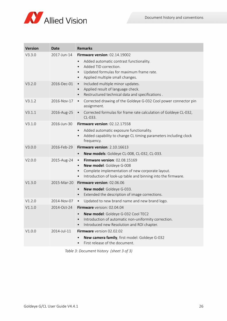
V3.3.0 2017-Jun-14 Firmware version: 02.14.19002
• Added automatic contrast functionality.
• Added TID correction.
• Updated formulas for maximum frame rate.
• Applied multiple small changes.
V3.2.0 2016-Dec-01 • Included multiple minor updates.
• Applied result of language check.
• Restructured technical data and specifications .
V3.1.2 2016-Nov-17 • Corrected drawing of the Goldeye G-032 Cool power connector pin assignment.
V3.1.1 2016-Aug-25 • Corrected formulas for frame rate calculation of Goldeye CL-032, CL-033.
V3.1.0 2016-Jun-30 Firmware version: 02.12.17558
• Added automatic exposure functionality.
• Added capability to change CL timing parameters including clock frequency.
V3.0.0 2016-Feb-29 Firmware version: 2.10.16613
• New models: Goldeye CL-008, CL-032, CL-033.
V2.0.0 2015-Aug-24 • Firmware version: 02.08.15169
• New model: Goldeye G-008
• Complete implementation of new corporate layout.
• Introduction of look-up table and binning into the firmware.
V1.3.0 2015-Mar-20 Firmware version: 02.06.06
• New model: Goldeye G-033.
• Extended the description of image corrections.
V1.2.0 2014-Nov-07 • Updated to new brand name and new brand logo.
V1.1.0 2014-Oct-24 Firmware version: 02.04.04
• New model: Goldeye G-032 Cool TEC2
• Introduction of automatic non-uniformity correction.
• Introduced new Resolution and ROI chapter.
V1.0.0 2014-Jul-11 Firmware version 02.02.02
• New camera family, first model: Goldeye G-032
• First release of the document.
Version Date Remarks
Table 3: Document history (sheet 3 of 3)
26Goldeye G/CL User Guide V4.4.1
Document history and conventions
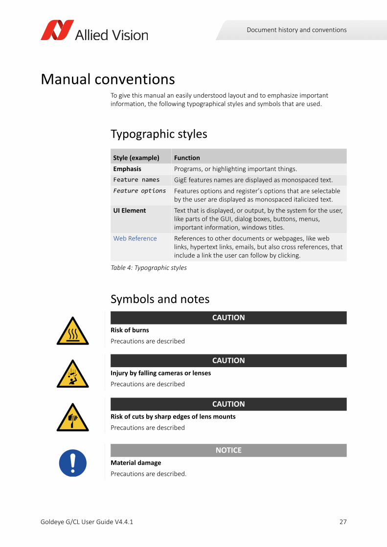
Manual conventionsTo give this manual an easily understood layout and to emphasize important information, the following typographical styles and symbols that are used.
Typographic styles
Symbols and notes
Style (example) Function
Emphasis Programs, or highlighting important things.
Feature names GigE features names are displayed as monospaced text.
Feature options Features options and register’s options that are selectable by the user are displayed as monospaced italicized text.
UI Element Text that is displayed, or output, by the system for the user, like parts of the GUI, dialog boxes, buttons, menus, important information, windows titles.
Web Reference References to other documents or webpages, like web links, hypertext links, emails, but also cross references, that include a link the user can follow by clicking.
Table 4: Typographic styles
CAUTION
Risk of burns
Precautions are described
CAUTION
Injury by falling cameras or lenses
Precautions are described
CAUTION
Risk of cuts by sharp edges of lens mounts
Precautions are described
NOTICE
Material damage
Precautions are described.
27Goldeye G/CL User Guide V4.4.1
Document history and conventions
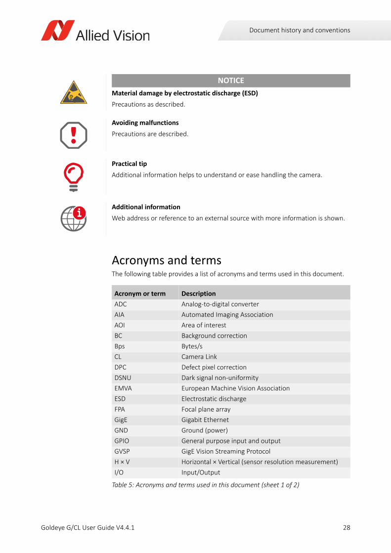
Acronyms and termsThe following table provides a list of acronyms and terms used in this document.
NOTICE
Material damage by electrostatic discharge (ESD)
Precautions as described.
Avoiding malfunctions
Precautions are described.
Practical tip
Additional information helps to understand or ease handling the camera.
Additional information
Web address or reference to an external source with more information is shown.
Acronym or term Description
ADC Analog-to-digital converter
AIA Automated Imaging Association
AOI Area of interest
BC Background correction
Bps Bytes/s
CL Camera Link
DPC Defect pixel correction
DSNU Dark signal non-uniformity
EMVA European Machine Vision Association
ESD Electrostatic discharge
FPA Focal plane array
GigE Gigabit Ethernet
GND Ground (power)
GPIO General purpose input and output
GVSP GigE Vision Streaming Protocol
H × V Horizontal × Vertical (sensor resolution measurement)
I/O Input/Output
Table 5: Acronyms and terms used in this document (sheet 1 of 2)
i
28Goldeye G/CL User Guide V4.4.1
Document history and conventions
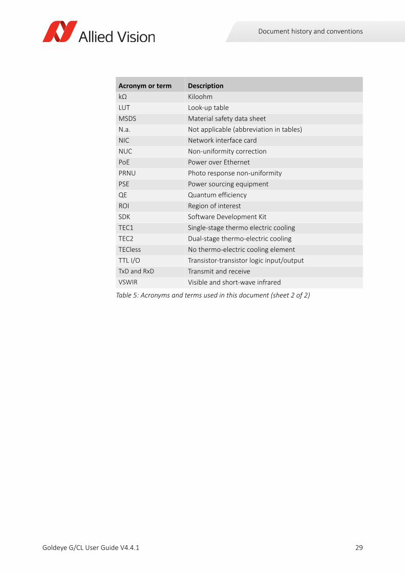
kΩ Kiloohm
LUT Look-up table
MSDS Material safety data sheet
N.a. Not applicable (abbreviation in tables)
NIC Network interface card
NUC Non-uniformity correction
PoE Power over Ethernet
PRNU Photo response non-uniformity
PSE Power sourcing equipment
QE Quantum efficiency
ROI Region of interest
SDK Software Development Kit
TEC1 Single-stage thermo electric cooling
TEC2 Dual-stage thermo-electric cooling
TECless No thermo-electric cooling element
TTL I/O Transistor-transistor logic input/output
TxD and RxD Transmit and receive
VSWIR Visible and short-wave infrared
Acronym or term Description
Table 5: Acronyms and terms used in this document (sheet 2 of 2)
29Goldeye G/CL User Guide V4.4.1
Compliance, safety, and intended use
Goldeye G/CL User Guide V4.4.1
This chapter includes:
Compliance notifications ...................................................... 31Intended use ......................................................................... 33Copyright and trademarks .................................................... 33Your safety............................................................................. 34Product safety ....................................................................... 35
30

Compliance, safety, and intended use
Compliance notifications
National regulations on disposal must be followed.
For customers in the US
Supplier Declaration of Conformity
Goldeye G/CL cameras comply with Part 15 of the FCC Rules. Operation is subject to the following two conditions:
1. This device may not cause harmful interference, and
2. This device must accept any interference received, including interference that may cause undesired operation.
Class B digital device
Note: This equipment has been tested and found to comply with the limits for a Class B digital device, pursuant to part 15 of the FCC Rules. These limits are designed to provide reasonable protection against harmful interference in a residential installation. This equipment generates, uses and can radiate radio frequency energy and, if not installed and used in accordance with the instructions, may cause harmful interference to radio communications. However, there is no guarantee that interference does not occur in a particular installation. If this equipment does cause harmful interference to radio or television reception, which can be determined by turning the equipment off and on, the user is encouraged to try to correct the interference by one or more of the following measures:
• Reorient or relocate the receiving antenna.
• Increase the separation between the equipment and receiver.
• Connect the equipment into an outlet on a circuit different from that to which the receiver is connected.
• Consult the dealer or an experienced radio/TV technician for help.
We caution the user that changes or modifications not expressly approved by the party responsible for compliance could void the user's authority to operate the equipment.
31Goldeye G/CL User Guide V4.4.1

Compliance, safety, and intended use
Party issuing Supplier's Declaration of ConformityAllied Vision Technologies GmbHTaschenweg 2a 07646 Stadtroda, Germany
T// +49 (36428) [email protected]
Responsible party - US contact informationAllied Vision Technologies, Inc.102 Pickering Way – Suite 502Exton, PA 19341, USA
T// +1 978 225 2030
Note: changes or modifications not expressly approved by the party responsible for compliance could void the user's authority to operate the equipment.
For customers in CanadaThis apparatus complies with the Class B limits for radio noise emissions set out in the Radio Interference Regulations.
CAN ICES-3 (B) / NMB-3 (B)
Pour utilisateurs au CanadaCet appareil est conforme aux normes classe B pour bruits radioélectriques, spécifiées dans le Règlement sur le brouillage radioélectrique.
CAN ICES-3 (B) / NMB-3 (B)
Avoid electromagnetic interferencesFor all power and interface connections, only use shielded cables or cables recommended by Allied Vision.
32Goldeye G/CL User Guide V4.4.1
Compliance, safety, and intended use
Intended useAllied Vision’s objective is the development, design, production, maintenance, servicing and distribution of digital cameras and components for image processing. We are offering standard products as well as customized solutions.
Intended use of Allied Vision product is the integration into Vision systems by professionals. All Allied Vision product is sold in a B2B setting.
Allied Vision isn’t a legal manufacturer of medical product. Instead, Allied Vision cameras and accessories may be used as components for medical product after design-in by the medical device manufacturer and based on a quality assurance agreement (QAA) between Allied Vision (supplier) and medical device manufacturer (customer). Allied Vision’s duties in that respect are defined by ISO 13485, clause 7.2 (customer-related processes, equivalent to ISO 9001, clause 8.2).
Copyright and trademarksAll text, pictures, and graphics are protected by copyright and other laws protecting intellectual property. All content is subject to change without notice.
All trademarks, logos, and brands cited in this document are property and/or copyright material of their respective owners. Use of these trademarks, logos, and brands does not imply endorsement.
Copyright © 2022 Allied Vision GmbH. All rights reserved.
33Goldeye G/CL User Guide V4.4.1
Compliance, safety, and intended use
Your safetyThis section informs about issues related to your personal safety. Descriptions explain how to avoid hazards and operate Goldeye G/CL cameras safely.
Handling lens mountsThe lens mount thread has sharp edges. Be careful these edges do not cut your skin when mounting or unmounting lenses.
Handling hot camerasIf you hold the camera in your hands during operation, your skin may get hurt. If you touch the camera when it is heated up, we recommend wearing protective gloves.
Providing optimum heat dissipationOperation outside the allowed temperature range can damage the camera. For best performance and to protect the camera from damage, keep the housing temperature in the specified operating temperature range.
Observe the following:
• To avoid camera crashes, operate the camera with a lens or lens adapter attached only.
• For maximum heat dissipation, affix the camera to a heat sink, using the mounting holes.
• Use mounting base and heat sink with large surface areas.
• Use a mounting base with a high thermal conductivity.
• Reduce ambient temperature. For example, in an outdoor application with direct sunlight, provide shading by an enclosure.
• Provide ventilation or other active cooling of camera, mounting base, and heat sink.
Camera mountingGoldeye G/CL cameras must be mounted using the mounting threads. If vibration is higher than specified, cameras can disconnect from the mounting. Falling cameras can hurt you. To avoid personal injury:
• Mount the camera according to the instructions in the installation chapters.
• Ensure, shock and vibration do not exceed the specified range as specified in the specifications chapter.
• For heavy or long lenses, use a lens support and apply tests.
34Goldeye G/CL User Guide V4.4.1
Compliance, safety, and intended use
Product safetyTo prevent material damage, read the following to understand how to safely handle and operate the camera.
Electrical connections
ESDESD is dangerous for electronic devices, especially when tools or hands get in contact with connectors. We recommend measures to avoid damage by ESD:
• Unpacking: Remove the camera from its anti-static packaging only when your body is grounded.
• Workplace: Use a static-safe workplace with static-dissipative mat and air ionization.
• Wrist strap: Wear a static-dissipative wrist strap to ground your body.
• Clothing: Wear ESD-protective clothing. Keep components away from your body and clothing. Even if you are wearing a wrist strap, your body is grounded but your clothes are not.
Cable connectionsProvide sufficient strain relief for all cable connections to avoid short circuits and malfunctions.
Camera powerOperating the camera beyond the specified range damages the camera.
Cameras can be powered using the I/O connector at an input range of 12 to 24 VDC, using a limited power source (LPS), according to IEC 62368-1 with maximum 2.0 A. The camera is not intended to be connected to a DC distribution network.
Alternatively, cameras can be powered over Ethernet. However, power consumption and heat generation are higher than with external power, using the I/O connector.
• Make sure that PoE power sourcing equipment is at least compliant to IEEE 802.3af/at.
• Only use power supplies that meet the insulation requirement according to PELV or SELV. For details, please refer to IEC 61140.
• If using external power supplies by third-party manufacturers, observe polarity to avoid damage to the camera electronics.
35Goldeye G/CL User Guide V4.4.1
Compliance, safety, and intended use
Optical componentsProvide the following conditions to keep dirt and droplets out of the optical system of camera and lens:
• Dust-free environment
• Low relative humidity
• No condensation.
When camera or lens are stored:
• Cover the lens mount with a protection foil or cap.
• Cover front and back lens with caps.
SensorSensors are sensitive to excessive radiation: focused sunlight, lasers, and X-rays can damage the sensor. Dirt and scratches can damage the sensor as well.
Goldeye G/CL cameras do not need additional cleaning. Cameras are cleaned before shipping. Incorrect cleaning can damage the sensor or the optical filter. Therefore, never clean the sensor or the optical filter.
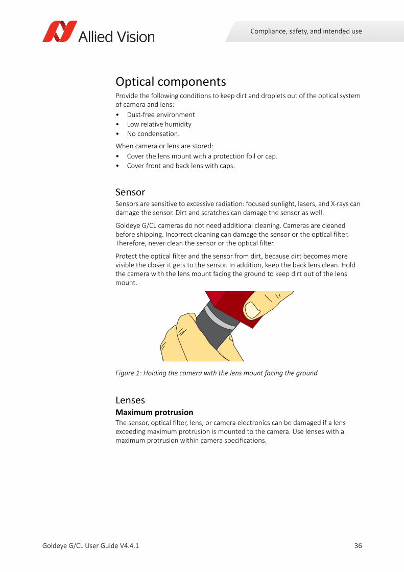
Protect the optical filter and the sensor from dirt, because dirt becomes more visible the closer it gets to the sensor. In addition, keep the back lens clean. Hold the camera with the lens mount facing the ground to keep dirt out of the lens mount.
LensesMaximum protrusionThe sensor, optical filter, lens, or camera electronics can be damaged if a lens exceeding maximum protrusion is mounted to the camera. Use lenses with a maximum protrusion within camera specifications.
Figure 1: Holding the camera with the lens mount facing the ground
36Goldeye G/CL User Guide V4.4.1
Installing the camera (GigE)
Goldeye G/CL User Guide V4.4.1
This chapter includes:
Touching hot cameras ........................................................... 38Electrostatic discharge .......................................................... 38Mounting the camera ........................................................... 38Mounting the lens................................................................. 41Configuring the host computer ............................................ 42Connecting your camera....................................................... 45Powering up the camera....................................................... 45Connecting to the host computer ........................................ 47Accessories............................................................................ 50
37
Installing the camera (GigE)
Touching hot cameras
Electrostatic discharge
Mounting the camera
CAUTION
Risk of burns
A camera in operation can reach temperature levels which could cause burns.
• Wear protective gloves when you touch a camera that is heated up.
• Ensure proper cooling of the camera.
NOTICE
ESD is dangerous for electronic devices, especially when tools or hands get in contact with connectors. We recommend measures to avoid damage by ESD:
• Unpacking: Remove the camera from its anti-static packaging only when your body is grounded.
• Workplace: Use a static-safe workplace with static-dissipative mat and air ionization.
• Wrist strap: Wear a static-dissipative wrist strap to ground your body.
• Clothing: Wear ESD-protective clothing. Keep components away from your body and clothing. Even if you are wearing a wrist strap, your body is grounded but your clothes are not.
CAUTION
Injury by falling cameras or lenses
A falling camera or lens can cause injury.
• Ensure proper mounting of cameras and lenses, especially for dynamic applications.
• Mount cameras as described in the instructions.
• Use all mounting holes of a camera side.
• Always make sure the mounting threads are intact.
• Fasten screws with maximum torque, using the entire thread engagement. For less thread engagement, see Adapting maximum torque values on page 40.
• We recommend you to apply thread locking.
• Use a lens support for heavy lenses.
38Goldeye G/CL User Guide V4.4.1
Installing the camera (GigE)
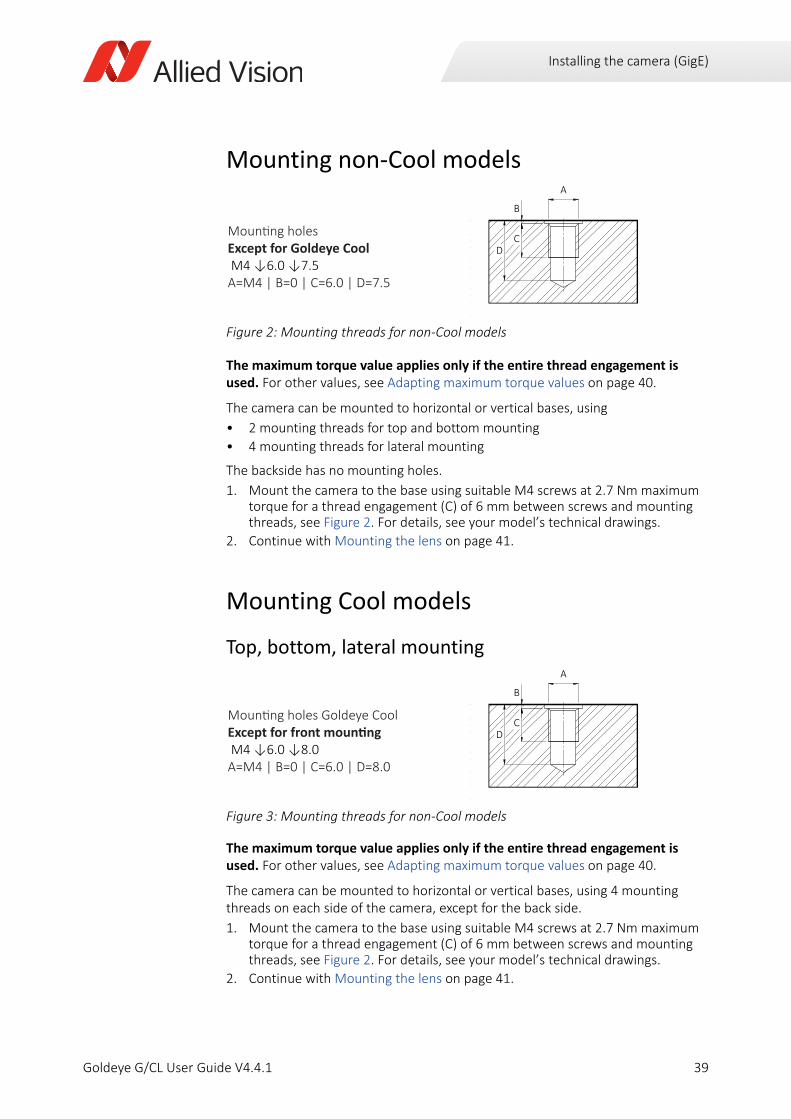
Mounting non-Cool models
The maximum torque value applies only if the entire thread engagement is used. For other values, see Adapting maximum torque values on page 40.
The camera can be mounted to horizontal or vertical bases, using
• 2 mounting threads for top and bottom mounting
• 4 mounting threads for lateral mounting
The backside has no mounting holes.
1. Mount the camera to the base using suitable M4 screws at 2.7 Nm maximum torque for a thread engagement (C) of 6 mm between screws and mounting threads, see Figure 2. For details, see your model’s technical drawings.
2. Continue with Mounting the lens on page 41.
Mounting Cool models
Top, bottom, lateral mounting
The maximum torque value applies only if the entire thread engagement is used. For other values, see Adapting maximum torque values on page 40.
The camera can be mounted to horizontal or vertical bases, using 4 mounting threads on each side of the camera, except for the back side.
1. Mount the camera to the base using suitable M4 screws at 2.7 Nm maximum torque for a thread engagement (C) of 6 mm between screws and mounting threads, see Figure 2. For details, see your model’s technical drawings.
2. Continue with Mounting the lens on page 41.
Figure 2: Mounting threads for non-Cool models
Figure 3: Mounting threads for non-Cool models
Except for Goldeye Cool D
B
C
A
D
B
C
A
39Goldeye G/CL User Guide V4.4.1
Installing the camera (GigE)
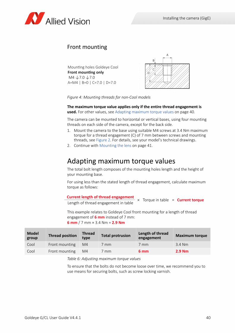
Front mounting
The maximum torque value applies only if the entire thread engagement is used. For other values, see Adapting maximum torque values on page 40.
The camera can be mounted to horizontal or vertical bases, using four mounting threads on each side of the camera, except for the back side.
1. Mount the camera to the base using suitable M4 screws at 3.4 Nm maximum torque for a thread engagement (C) of 7 mm between screws and mounting threads, see Figure 2. For details, see your model’s technical drawings.
2. Continue with Mounting the lens on page 41.
Adapting maximum torque valuesThe total bolt length composes of the mounting holes length and the height of your mounting base.
For using less than the stated length of thread engagement, calculate maximum torque as follows:
This example relates to Goldeye Cool front mounting for a length of thread engagement of 6 mm instead of 7 mm:6 mm / 7 mm × 3.4 Nm = 2.9 Nm
To ensure that the bolts do not become loose over time, we recommend you to use means for securing bolts, such as screw locking varnish.
Figure 4: Mounting threads for non-Cool models
Current length of thread engagement× Torque in table = Current torque
Length of thread engagement in table
Model group
Thread position Thread type
Total protrusion Length of thread engagement
Maximum torque
Cool Front mounting M4 7 mm 7 mm 3.4 Nm
Cool Front mounting M4 7 mm 6 mm 2.9 Nm
Table 6: Adjusting maximum torque values
D
B
C
A
40Goldeye G/CL User Guide V4.4.1
Installing the camera (GigE)
1/4” -20 UNC mounting threadTo attach the camera to the common mounting plate of tripods used in photography, a 1/4” -20 UNC mounting thread is located on the camera bottom.
Mounting the lens
Goldeye G cameras offer various lens mounts for installing a lens including C-Mount, F-Mount, and M42-Mount. Lenses can be purchased directly from Allied Vision or from an Allied Vision distribution partner. Users need to select the desired focal length of the lens and appropriate optical format for the target camera model.
CAUTION
Injury by falling cameras or lenses
A falling camera or lens can cause injury.
• Ensure proper mounting of cameras and lenses, especially for dynamic applications.
• Mount cameras as described in the instructions.
• Use a lens support for heavy lenses.
CAUTION
Risk of cuts by sharp edges of lens mounts
The threads of the lens mount can have sharp edges.
Be careful when mounting or unmounting lenses.
NOTICE
Provide the following conditions to keep dirt and droplets out of the optical system of camera and lens:
• Dust-free environment
• Low relative humidity
• No condensation
To keep dirt out of the lens mount, hold the camera with the lens mount facing the ground. Keep optical filter and camera back lens clean, because dirt becomes more visible the closer it gets to the sensor.
NOTICE
Image sensors are sensitive to excessive radiation: focused sunlight, lasers, and X-rays can damage the sensor.
41Goldeye G/CL User Guide V4.4.1
Installing the camera (GigE)
For more information on lens mount options for your Goldeye G camera, see the Modular Concept. For information on available lenses and accessories for your camera, see the Accessories webpage.
Configuring the host computerGoldeye G cameras can operate on 100 Megabit or Gigabit speed NICs. To reach the maximum camera frame rate, a Gigabit speed NIC with jumbo packet support is required.
If your host computer has an available Ethernet port, this can be used with your Goldeye G camera. We recommend that your camera system uses a dedicated Ethernet port not shared with internet or local area networks. If more ports are needed, or your existing NIC is unable to operate at Gigabit Ethernet speeds, installing additional hardware may be required.
• For desktop systems, install a PCI Express bus NIC.
• For laptops, use an expansion slot via a Gigabit Ethernet Express card.
Usage on mixed-use networks (with printers, internet or email, and other devices) is possible but may impact camera performance, for example, frame rate. Check with your IT administrator if required for network configuration.
For a list of Ethernet adapters available for purchase from Allied Vision, please contact Allied Vision sales representative or your local Allied Vision distribution partner.
Compatible interface slot
Verify that there is an available and compatible interface slot on the host computer before purchasing the desired NIC.
42Goldeye G/CL User Guide V4.4.1
Installing the camera (GigE)
Installing the NIC driverInstall the network card driver from your network card manufacturer. If no installation application is provided, update the driver manually.
To update the driver manually1. Click the Start icon and select Control Panel in the menu.
2. Click View by Large Icons and select Device Manager in the list.
3. Under Network Adapters, locate the Ethernet NIC, right-click the entry, and select Update Driver Software in the menu.
4. Select the Search automatically for updated driver software or Browse my computer for driver software.
5. Click Close after the driver has been installed.
Optional: Modifying NIC IP addressAfter the initial NIC hardware installation, connect the NIC directly to the camera. The default configuration assigns an IP address automatically using the Link-Local Address range of 169.254.xxx.xxx or an address defined by the DHCP server, if present.
Users can fix the NIC address to minimize the time required for a camera to be recognized by the host application.
To connect to the camera, edit the host computer’s adapter settings and configure the following settings:
• IP Address: 169.254.100.1
• Subnet mask: 255.255.0.0
• Default gateway: blank
When systems employ multiple NICs connected to multiple cameras the address of the NICs should be set. Each NIC or NIC card port requires a unique IP address.
For example:
NIC 1:
• IP Address: 169.254.100.1
• Subnet mask: 255.255.0.0
• Default gateway: blank
NIC 2:
• IP Address: 169.254.100.2
• Subnet mask: 255.255.0.0
• Default gateway: blank
43Goldeye G/CL User Guide V4.4.1
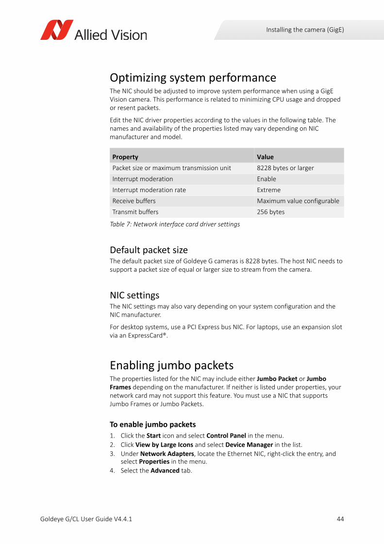
Installing the camera (GigE)
Optimizing system performanceThe NIC should be adjusted to improve system performance when using a GigE Vision camera. This performance is related to minimizing CPU usage and dropped or resent packets.
Edit the NIC driver properties according to the values in the following table. The names and availability of the properties listed may vary depending on NIC manufacturer and model.
Default packet sizeThe default packet size of Goldeye G cameras is 8228 bytes. The host NIC needs to support a packet size of equal or larger size to stream from the camera.
NIC settingsThe NIC settings may also vary depending on your system configuration and the NIC manufacturer.
For desktop systems, use a PCI Express bus NIC. For laptops, use an expansion slot via an ExpressCard®.
Enabling jumbo packetsThe properties listed for the NIC may include either Jumbo Packet or Jumbo Frames depending on the manufacturer. If neither is listed under properties, your network card may not support this feature. You must use a NIC that supports Jumbo Frames or Jumbo Packets.
To enable jumbo packets
1. Click the Start icon and select Control Panel in the menu.
2. Click View by Large Icons and select Device Manager in the list.
3. Under Network Adapters, locate the Ethernet NIC, right-click the entry, and select Properties in the menu.
4. Select the Advanced tab.
Property Value
Packet size or maximum transmission unit 8228 bytes or larger
Interrupt moderation Enable
Interrupt moderation rate Extreme
Receive buffers Maximum value configurable
Transmit buffers 256 bytes
Table 7: Network interface card driver settings
44Goldeye G/CL User Guide V4.4.1
Installing the camera (GigE)
5. Select the property Jumbo Packet and set the value to 9014 Bytes.
6. Click OK to save the setting.
Connecting your cameraUse a CAT5e or higher rated Ethernet cable to connect the camera to the NIC. Crossover cabling is not required but does work. The camera has circuitry to determine if a crossover cable is being used.
Powering up the cameraA camera power adapter for each Goldeye G camera is available from Allied Vision. See the Specifications chapter for connector definition and voltage specifications.
Support by various Gigabit Ethernet cards
The settings list in the advanced adapter settings may vary between various types and brands of Gigabit Ethernet network cards. Common expressions are Jumbo Frames or Jumbo Packet.
If Jumbo Frames or Jumbo Packet does not appear in this list, your network card may not support it. Without this capability, you may not be able to achieve the full performance of the camera. Refer to Specifications (GigE models) on page 75 for details on power consumption.
We recommend CAT5e or higher rated Ethernet cables. A cable with a lower rating may not sustain peak interface bandwidth; leading to lost connectivity or dropped frames coming from the camera.
A 12 V power adapter with Hirose connector is available for purchase from Allied Vision:
• Order code: 13867 (Desktop power supply Goldeye G Cool)
• Order code: 13869 (Desktop power supply Goldeye G)
• Order code: 13866 (AC power cable, 1.8 m, US to C13)
• Order code: 13865 (AC power cable, 1.8 m, EU to C13)
45Goldeye G/CL User Guide V4.4.1
Installing the camera (GigE)
NOTICE
• Use only DC power supplies with insulated cases.
• For all power connections, use only shielded cables to avoid electromagnetic interference.
• Goldeye G cameras can source power from:
- IEEE 802.3at Type 1 Class 0 (Goldeye G TEC1, Goldeye G TECless), IEEE 802.3at Type 1 compliant PoE power sourcing equipment devices such as switches, injectors, or NICs.
- IEEE 802.3at Type 2 Class 4 (Goldeye G Cool TEC2 models only), IEEE 802.3at Type 2 compliant PoE power sourcing equipment devices such as switches, injectors, or NICs.
NOTICE
Verify all external connections in terms of voltage levels, power requirements, voltage polarity, and signal integrity prior to powering the device.
NOTICE
Don’t operate the camera beyond the environmental specifications. See environmental specifications limits in the Specifications section of this document. Special care must be taken to maintain an operating temperature as specified in the Specifications chapter.
NOTICE
Operation outside the allowed temperature range can damage the camera. For best performance and to protect the camera from damage, keep the housing temperature in the specified operating temperature range.
Observe the following:
• To avoid camera crashes, operate the camera with a lens or lens adapter attached only.
• For maximum heat dissipation, affix the camera to a heat sink, using the mounting holes.
- Use mounting base and heat sink with large surface areas.
- Use a mounting base with a high thermal conductivity.
• Reduce ambient temperature. For example, in an outdoor application with direct sunlight, provide shading by an enclosure.
• Provide ventilation or other active cooling of camera, mounting base, and heat sink.
The camera is not intended to be connected to a DC distribution network. The maximum length for I/O cables must not exceed 30 meters.
46Goldeye G/CL User Guide V4.4.1
Installing the camera (GigE)
To power up the camera, plug the 12-pin Hirose connector into the camera and wait for the boot phase to complete. For Cool models, use the 4-pin Hirose connector. The boot phase is indicated by a steady flashing of the Ethernet status LEDs.
For all available power supply options and all suitable connectors refer to Power supplies on page 179.
Hardware SelectionCameras powered by both the Hirose I/O port and the Gigabit Ethernet port use the power provided by Hirose I/O port only.
Powering the camera via PoENote the following when using PoE accessories with PoE-capable GigE cameras:
• Goldeye G TEC1 and Goldeye G TECless cameras conform to the IEEE 802.3af (PoE) Type 1 Class 0 standard.
• Goldeye G Cool TEC2 models cameras conform to the IEEE 802.3at (PoE+) Type 2 Class 4 standard.
• Ensure that your PSE provides data over all four pairs.
• If the PSE uses only two out of four pairs for data, operation is limited to 10/100 Mbps. This translates to lower frame rates.
• If the PSE uses all four pairs for data, operation is in Gigabit (1000 Mbps) mode. Thus, allowing you to achieve the maximum possible frame rate.
Connecting to the host computerAfter you have installed Vimba Viewer or a third-party application to your host computer, connect your Goldeye G camera via an Ethernet cable. If your camera is not PoE powered, connect the Hirose cable to power the camera. Goldeye G cameras are GigE Vision v1.2 compliant. This means they are compatible with third-party software that offers a GigE Vision driver.
Goldeye G cameras work with the following software options:
• Vimba Viewer or Vimba SDK
• Third-party software solutions
47Goldeye G/CL User Guide V4.4.1
Installing the camera (GigE)
Allied Vision softwareSoftware packages provided by Allied Vision are free of charge and contain such as:
• Drivers
• SDK for camera control and image acquisition
• Examples based on the provided APIs of the SDK
• Documentation and release notes
• Viewer application to operate and configure the cameras
Vimba is Allied Vision's GenICam-based SDK with transport layers for all Allied Vision cameras with GigE Vision, USB3 Vision, IEEE 1394, and Camera Link (CL) interface. Vimba runs on Windows, Linux, and Linux for ARM. You can port your source code from Windows to Linux or cross-compile from a Linux PC to an embedded system.
Vimba provides APIs for C, C++, and .NET. Users who quickly want to develop a straightforward application love the simplicity of the C API or the .NET API.
Advanced users with high demands appreciate the C++ API, which is designed as a highly efficient and sophisticated API for advanced object-oriented programming including the STL (standard template library), shared pointers, and interface classes.
Vimba includes programming examples in C, C++, and C# and an extensive user documentation.
Third-party softwareIn addition to the software provided by Allied Vision, there are numerous GigE Vision standard compliant third-party software options available. In general, third-party software provides increased functionality such as image processing and video recording.
GenICam-based third-party software automatically connects with Vimba's transport layers. Additionally, Vimba includes the Cognex Adapter for VisionPro.
Download Vimba SDK from www.alliedvision.com/en/products/software. After installing, documentation is located under \Program Files\Allied Vision\Vimba.
i
48Goldeye G/CL User Guide V4.4.1
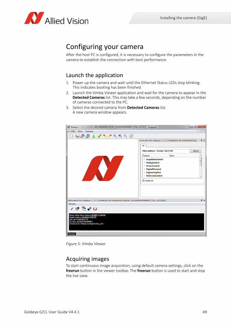
Installing the camera (GigE)
Configuring your cameraAfter the host PC is configured, it is necessary to configure the parameters in the camera to establish the connection with best performance.
Launch the application1. Power up the camera and wait until the Ethernet Status LEDs stop blinking.
This indicates booting has been finished.
2. Launch the Vimba Viewer application and wait for the camera to appear in the Detected Cameras list. This may take a few seconds, depending on the number of cameras connected to the PC.
3. Select the desired camera from Detected Cameras list. A new camera window appears.
Acquiring imagesTo start continuous image acquisition, using default camera settings, click on the freerun button in the viewer toolbar. The freerun button is used to start and stop the live view.
Figure 5: Vimba Viewer
49Goldeye G/CL User Guide V4.4.1
Installing the camera (GigE)
Troubleshooting
Is the camera getting power?Check the GigE status LED at the GigE port on the backside of the camera. Once the camera is booted, the green LED remains lit as long as the camera is connected to power.
The status LED codes for Goldeye G cameras are described in the section GigE status LEDs on page 206.
AccessoriesWe offer a wide range of accessories for use with Goldeye G cameras including:
• GigE accessories such as standard GigE components and PoE/PoE+ capable GigE components.
• Lenses for corresponding sensor sizes and resolutions.
Contact your Allied Vision Sales team or your local Allied Vision distribution partner for information on accessories and lens recommendations.
50Goldeye G/CL User Guide V4.4.1
Installing the camera (CL)
Goldeye G/CL User Guide V4.4.1
This chapter includes:
Touching hot cameras ........................................................... 52Electrostatic discharge .......................................................... 52Mounting the camera ........................................................... 52Mounting the lens................................................................. 55Installing hardware and software ......................................... 56Connecting your camera....................................................... 57Powering up the camera....................................................... 57Connecting to the host computer ........................................ 58Camera control and image viewing ...................................... 60
51

Installing the camera (CL)
Touching hot cameras
Electrostatic discharge
Mounting the camera
CAUTION
Risk of burns
A camera in operation can reach temperature levels which could cause burns.
• Wear protective gloves when you touch a camera that is heated up.
• Ensure proper cooling of the camera.
NOTICE
ESD is dangerous for electronic devices, especially when tools or hands get in contact with connectors. We recommend measures to avoid damage by ESD:
• Unpacking: Remove the camera from its anti-static packaging only when your body is grounded.
• Workplace: Use a static-safe workplace with static-dissipative mat and air ionization.
• Wrist strap: Wear a static-dissipative wrist strap to ground your body.
• Clothing: Wear ESD-protective clothing. Keep components away from your body and clothing. Even if you are wearing a wrist strap, your body is grounded but your clothes are not.
CAUTION
Injury by falling cameras or lenses
A falling camera or lens can cause injury.
• Ensure proper mounting of cameras and lenses, especially for dynamic applications.
• Mount cameras as described in the instructions.
• Use all mounting holes of a camera side.
• Always make sure the mounting threads are intact.
• Fasten screws with maximum torque, using the entire thread engagement. For less thread engagement, see Adapting maximum torque values on page 54.
• We recommend you to apply thread locking.
• Use a lens support for heavy lenses.
52Goldeye G/CL User Guide V4.4.1

Installing the camera (CL)
Mounting non-Cool models
The maximum torque value applies only if the entire thread engagement is used. For other values, see Adapting maximum torque values on page 54.
The camera can be mounted to horizontal or vertical bases, using
• 2 mounting threads for top and bottom mounting
• 4 mounting threads for lateral mounting
The backside has no mounting holes.
1. Mount the camera to the base using suitable M4 screws at 2.7 Nm maximum torque for a thread engagement (C) of 6 mm between screws and mounting threads, see Figure 6. For details, see your model’s technical drawings.
2. Continue with Mounting the lens on page 55.
Mounting Cool models
Top, bottom, lateral mounting
The maximum torque value applies only if the entire thread engagement is used. For other values, see Adapting maximum torque values on page 54.
The camera can be mounted to horizontal or vertical bases, using 4 mounting threads on each side of the camera, except for the back side.
1. Mount the camera to the base using suitable M4 screws at 2.7 Nm maximum torque for a thread engagement (C) of 6 mm between screws and mounting threads, see Figure 6. For details, see your model’s technical drawings.
2. Continue with Mounting the lens on page 55.
Figure 6: Mounting threads for non-Cool models
Figure 7: Mounting threads for non-Cool models
Except for Goldeye Cool D
B
C
A
D
B
C
A
53Goldeye G/CL User Guide V4.4.1

Installing the camera (CL)
Front mounting
The maximum torque value applies only if the entire thread engagement is used. For other values, see Adapting maximum torque values on page 54.
The camera can be mounted to horizontal or vertical bases, using four mounting threads on each side of the camera, except for the back side.
1. Mount the camera to the base using suitable M4 screws at 3.4 Nm maximum torque for a thread engagement (C) of 7 mm between screws and mounting threads, see Figure 6. For details, see your model’s technical drawings.
2. Continue with Mounting the lens on page 55.
Adapting maximum torque valuesThe total bolt length composes of the mounting holes length and the height of your mounting base.
For using less than the stated length of thread engagement, calculate maximum torque as follows:
This example relates to Goldeye Cool front mounting for a length of thread engagement of 6 mm instead of 7 mm:6 mm / 7 mm × 3.4 Nm = 2.9 Nm
To ensure that the bolts do not become loose over time, we recommend you to use means for securing bolts, such as screw locking varnish.
Figure 8: Mounting threads for non-Cool models
Current length of thread engagement× Torque in table = Current torque
Length of thread engagement in table
Model group
Thread position Thread type
Total protrusion Length of thread engagement
Maximum torque
Cool Front mounting M4 7 mm 7 mm 3.4 Nm
Cool Front mounting M4 7 mm 6 mm 2.9 Nm
Table 8: Adjusting maximum torque values
D
B
C
A
54Goldeye G/CL User Guide V4.4.1
Installing the camera (CL)
1/4” -20 UNC mounting threadTo attach the camera to the common mounting plate of tripods used in photography, a 1/4” -20 UNC mounting thread is located on the camera bottom.
Mounting the lens
Goldeye CL cameras offer various lens mounts for installing a lens including C-Mount, F-Mount, and M42-Mount. Lenses can be purchased directly from Allied Vision or from an Allied Vision distribution partner. Users need to select the desired focal length of the lens and appropriate optical format for the target camera model.
CAUTION
Injury by falling cameras or lenses
A falling camera or lens can cause injury.
• Ensure proper mounting of cameras and lenses, especially for dynamic applications.
• Mount cameras as described in the instructions.
• Use a lens support for heavy lenses.
CAUTION
Risk of cuts by sharp edges of lens mounts
The threads of the lens mount can have sharp edges.
Be careful when mounting or unmounting lenses.
NOTICE
Provide the following conditions to keep dirt and droplets out of the optical system of camera and lens:
• Dust-free environment
• Low relative humidity
• No condensation
To keep dirt out of the lens mount, hold the camera with the lens mount facing the ground. Keep optical filter and camera back lens clean, because dirt becomes more visible the closer it gets to the sensor.
NOTICE
Image sensors are sensitive to excessive radiation: focused sunlight, lasers, and X-rays can damage the sensor.
55Goldeye G/CL User Guide V4.4.1
Installing the camera (CL)
For more information on lens mount options for your Goldeye CL camera, see the Modular Concept. For information on available lenses and accessories for your camera, see the Accessories webpage.
Installing hardware and software
Frame grabbersAlmost every frame grabber compatible to Camera Link Base can be used to operate a Goldeye CL camera.
Installing a frame grabberFor the installation of a frame grabber, the computer must meet the minimum system requirements of the frame grabber.
Find the requirements in the technical manual of the frame grabber.
Refer also to the frame grabber installation manual provided by the manufacturer regarding installation details.
Installing frame grabber softwareRead the frame grabber software installation guide provided by the frame grabber manufacturer.
Installing camera softwareThis section presents instructions for software installation specific to Windows 7. Goldeye CL cameras can be operated under later versions of Windows as well. Allied Vision offers Vimba as the main SDK for its CL cameras.
Application Note: Usage of frame grabbers with Goldeye CL cameras
Refer to this application note for detailed requirements:
www.alliedvision.com/fileadmin/content/documents/products/cameras/Goldeye_2/appnote/Goldeye-Framegrabber_AppNote_en.pdf
More information about frame grabbers:
For more information about compatibility of various frame grabber models and system installation refer to the application note Usage of Frame grabbers with Goldeye CL Cameras, which is available from the Allied Vision website:
www.alliedvision.com/en/support/technical-documentation/goldeye-gcl-documentation
i
i
56Goldeye G/CL User Guide V4.4.1
Installing the camera (CL)
To install the Vimba SDK plus corresponding Vimba Viewer, read Installing Vimba Viewer on Windows on page 57.
Note that there is no Linux support for Camera Link with Vimba.
Installing Vimba Viewer on WindowsYou can install the Vimba Viewer on Windows 7, Windows 8.1, and Windows 10. To install the Vimba Viewer on Windows, follow these steps:
Step 1: To start the installation, run the file Vimba_v2.0_Windows.exe.
Step 2: Select an installation level suitable for you.
Step 3: Click Start. The installer will guide you through the installation process.
Connecting your cameraTo connect the camera to the host application, use a Camera Link cable with an SDR-26 connector for the camera side.
To retrieve information about the required connector type for the frame grabber (either MDR-26 or SDR-26), refer to the frame grabber manual. A list of compatible Camera Link cables is provided on our website.
Powering up the cameraA camera power adapter for each Goldeye CL camera is available from Allied Vision. See the Specifications chapter for connector definition and voltage specifications.
Frame grabber configuration files
Some frame grabbers applications use configuration files to setup the grabber for a certain camera. Allied Vision can provide files for the Goldeye CL series for various frame grabbers.
For more information, please visit www.alliedvision.com/en/about-us/contact-us/technical-support-repair-/-rma.
A 12 V power adapter with Hirose connector is available for purchase from Allied Vision:
• Order code: 13867 (Desktop power supply Goldeye CL Cool)
• Order code: 13869 (Desktop power supply Goldeye CL)
• Order code: 13866 (AC power cable, 1.8 m, US to C13)
• Order code: 13865 (AC power cable, 1.8 m, EU to C13)
i
57Goldeye G/CL User Guide V4.4.1
Installing the camera (CL)
To power up the camera, plug the 12-pin Hirose connector into the camera and wait for the boot phase to complete. For Goldeye Cool models, use the 4-pin Hirose connector. The boot phase is indicated by a steady flashing of the Camera Link status LED.
Connecting to the host computerAfter you have installed Vimba Viewer or a third-party application to your host computer, connect your Goldeye CL camera via Camera Link cable with an SDR-26 connector for the camera side.
NOTICE
Verify all external connections in terms of voltage levels, power requirements, voltage polarity, and signal integrity prior to powering the device.
NOTICE
Don’t operate the camera beyond the environmental specifications. See environmental specifications limits in the Specifications section of this document. Special care must be taken to maintain an operating temperature as specified in the Specifications chapter.
NOTICE
Operation outside the allowed temperature range can damage the camera. For best performance and to protect the camera from damage, keep the housing temperature in the specified operating temperature range.
Observe the following:
• To avoid camera crashes, operate the camera with a lens or lens adapter attached only.
• For maximum heat dissipation, affix the camera to a heat sink, using the mounting holes.
- Use mounting base and heat sink with large surface areas.
- Use a mounting base with a high thermal conductivity.
• Reduce ambient temperature. For example, in an outdoor application with direct sunlight, provide shading by an enclosure.
• Provide ventilation or other active cooling of camera, mounting base, and heat sink.
The camera is not intended to be connected to a DC distribution network. The maximum length for I/O cables must not exceed 30 meters.
58Goldeye G/CL User Guide V4.4.1
Installing the camera (CL)
To retrieve information about the required connector type for the frame grabber (either MDR-26 or SDR-26), refer to the frame grabber manual.
Goldeye CL cameras work with the following software options:
• Vimba Viewer or Vimba SDK
• Third-party software solutions
To acquire images the frame grabber SDK must be used.
Allied Vision softwareAll software packages provided by Allied Vision are free of charge and contain the following components:
• Drivers
• SDK for camera control and image acquisition
• Examples based on the provided APIs of the SDK
• Documentation and release notes
• Viewer application to operate and configure the cameras
Vimba is Allied Vision's GenICam-based SDK with transport layers for all Allied Vision cameras with GigE Vision, USB3 Vision, IEEE 1394, and Camera Link interface. Vimba runs on Windows, Linux, and Linux for ARM. You can port your source code from Windows to Linux or cross-compile from a Linux PC to an embedded system.
Vimba provides APIs for C, C++, and .NET. Users who quickly want to develop a straightforward application love the simplicity of the C API or the .NET API.
Advanced users with high demands appreciate the C++ API, which is designed as a highly efficient and sophisticated API for advanced object-oriented programming including the STL (standard template library), shared pointers, and interface classes.
Vimba includes programming examples in C, C++, and C# and an extensive user documentation.
Third-party softwareIn addition to the software provided by Allied Vision, there are numerous GigE Vision standard compliant third-party software options available. In general, third-party software provides increased functionality such as image processing and video recording.
Vimba Viewer documentation
Vimba Viewer documentation is included with the software download. After Vimba Viewer is installed on your host computer, documentation is located under \Program Files\Allied Vision\Vimba.
59Goldeye G/CL User Guide V4.4.1
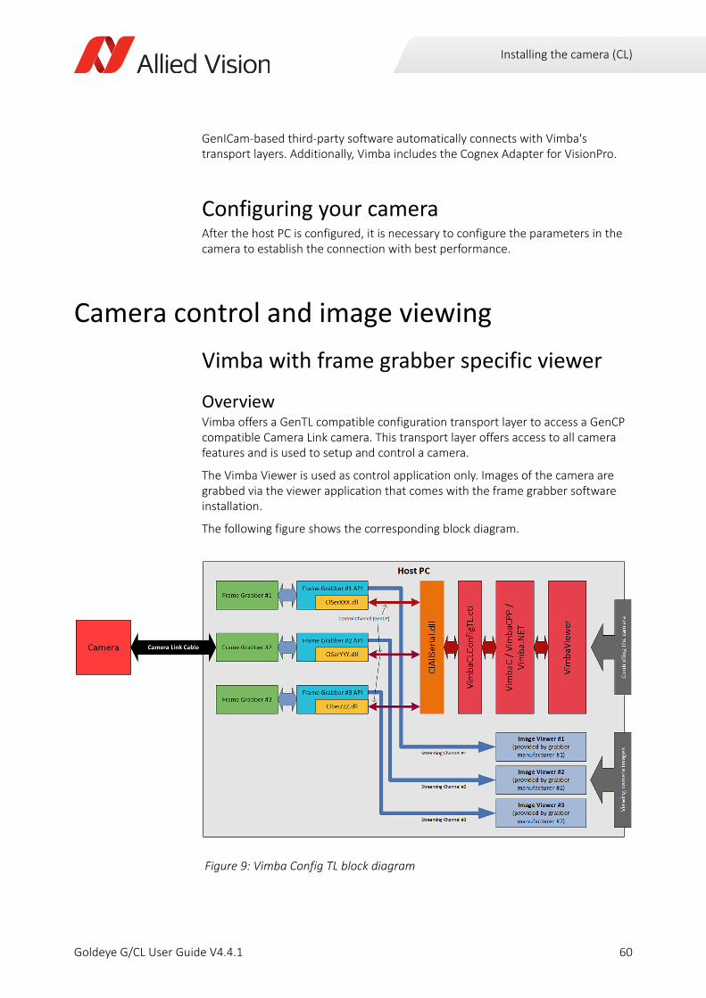
Installing the camera (CL)
GenICam-based third-party software automatically connects with Vimba's transport layers. Additionally, Vimba includes the Cognex Adapter for VisionPro.
Configuring your cameraAfter the host PC is configured, it is necessary to configure the parameters in the camera to establish the connection with best performance.
Camera control and image viewing
Vimba with frame grabber specific viewer
OverviewVimba offers a GenTL compatible configuration transport layer to access a GenCP compatible Camera Link camera. This transport layer offers access to all camera features and is used to setup and control a camera.
The Vimba Viewer is used as control application only. Images of the camera are grabbed via the viewer application that comes with the frame grabber software installation.
The following figure shows the corresponding block diagram.
Figure 9: Vimba Config TL block diagram
60Goldeye G/CL User Guide V4.4.1
Installing the camera (CL)
Adjusting the transfer speed for your frame grabberNot all frame grabbers support the same maximum data transfer speed. The maximum bit rate supported by various frame grabbers is vastly different. Therefore, the default bit rate for use of Vimba with Camera Link is set to the minimum bit rate of 9600 bits per second.
If your frame grabber supports a higher bit rate, it is advantageous to increase the bit rate in Vimba to the highest bit rate that the frame grabber supports.
To increase the bit rate, follow these steps:
Step 1: Open the file VimbaCLConfigTL.xml. You find it in the VIMBA_HOME directory, which is typically one of the following (for Vimba 2.1 - adjust the path for Vimba 2.0 accordingly).
• C:\Program Files\Allied Vision\Vimba_2.1\VimbaCLConfigTL\bin\Win32
• C:\Program Files\Allied Vision\Vimba_2.1\VimbaCLConfigTL\bin\Win64
These XML files include the modifiable settings, by default the bit rate is denoted as follows:
Set this number to the highest bit rate that your frame grabber supports, the highest possible value is 912600 bits per second.Save the file and close.
Step 2: Restart Vimba and restart the Goldeye CL camera.
Result: All operations requiring data exchange, especially a firmware update, increase significantly in speed.
Take note when changing the transfer speed
• Always change the bit rate using Vimba. Do not try to change the bit rate from within the camera, this might cause the camera to stop working and require a restart.
• The steps outlined are applicable for Vimba, they are not applicable for any frame grabber SDK.
<DefaultBaudRate>9600</DefaultBaudRate>
61Goldeye G/CL User Guide V4.4.1
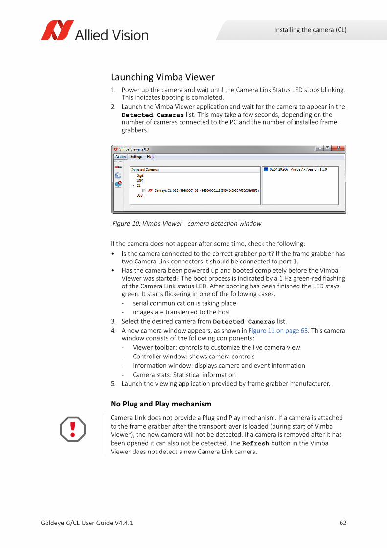
Installing the camera (CL)
Launching Vimba Viewer1. Power up the camera and wait until the Camera Link Status LED stops blinking.
This indicates booting is completed.
2. Launch the Vimba Viewer application and wait for the camera to appear in the Detected Cameras list. This may take a few seconds, depending on the number of cameras connected to the PC and the number of installed frame grabbers.
If the camera does not appear after some time, check the following:
• Is the camera connected to the correct grabber port? If the frame grabber has two Camera Link connectors it should be connected to port 1.
• Has the camera been powered up and booted completely before the Vimba Viewer was started? The boot process is indicated by a 1 Hz green-red flashing of the Camera Link status LED. After booting has been finished the LED stays green. It starts flickering in one of the following cases.
- serial communication is taking place
- images are transferred to the host
3. Select the desired camera from Detected Cameras list.
4. A new camera window appears, as shown in Figure 11 on page 63. This camera window consists of the following components:
- Viewer toolbar: controls to customize the live camera view
- Controller window: shows camera controls
- Information window: displays camera and event information
- Camera stats: Statistical information
5. Launch the viewing application provided by frame grabber manufacturer.
No Plug and Play mechanism
Figure 10: Vimba Viewer - camera detection window
Camera Link does not provide a Plug and Play mechanism. If a camera is attached to the frame grabber after the transport layer is loaded (during start of Vimba Viewer), the new camera will not be detected. If a camera is removed after it has been opened it can also not be detected. The Refresh button in the Vimba Viewer does not detect a new Camera Link camera.
62Goldeye G/CL User Guide V4.4.1
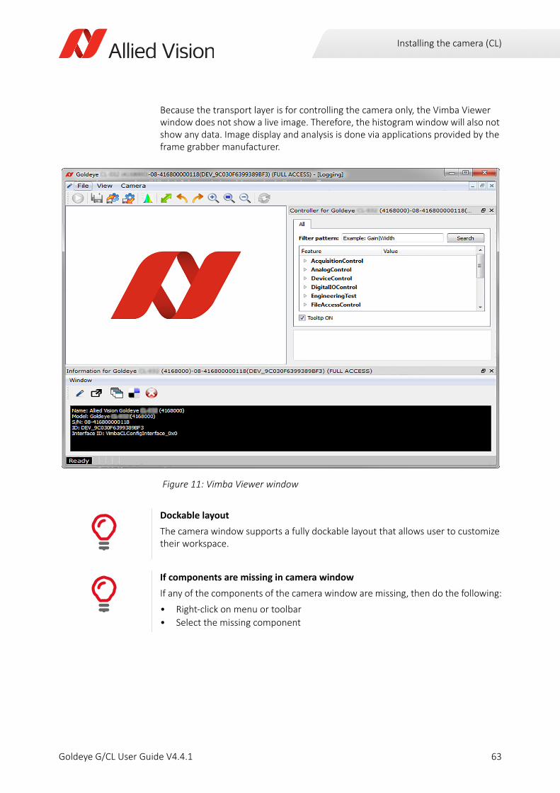
Installing the camera (CL)
Because the transport layer is for controlling the camera only, the Vimba Viewer window does not show a live image. Therefore, the histogram window will also not show any data. Image display and analysis is done via applications provided by the frame grabber manufacturer.
Figure 11: Vimba Viewer window
Dockable layout
The camera window supports a fully dockable layout that allows user to customize their workspace.
If components are missing in camera window
If any of the components of the camera window are missing, then do the following:
• Right-click on menu or toolbar
• Select the missing component
63Goldeye G/CL User Guide V4.4.1
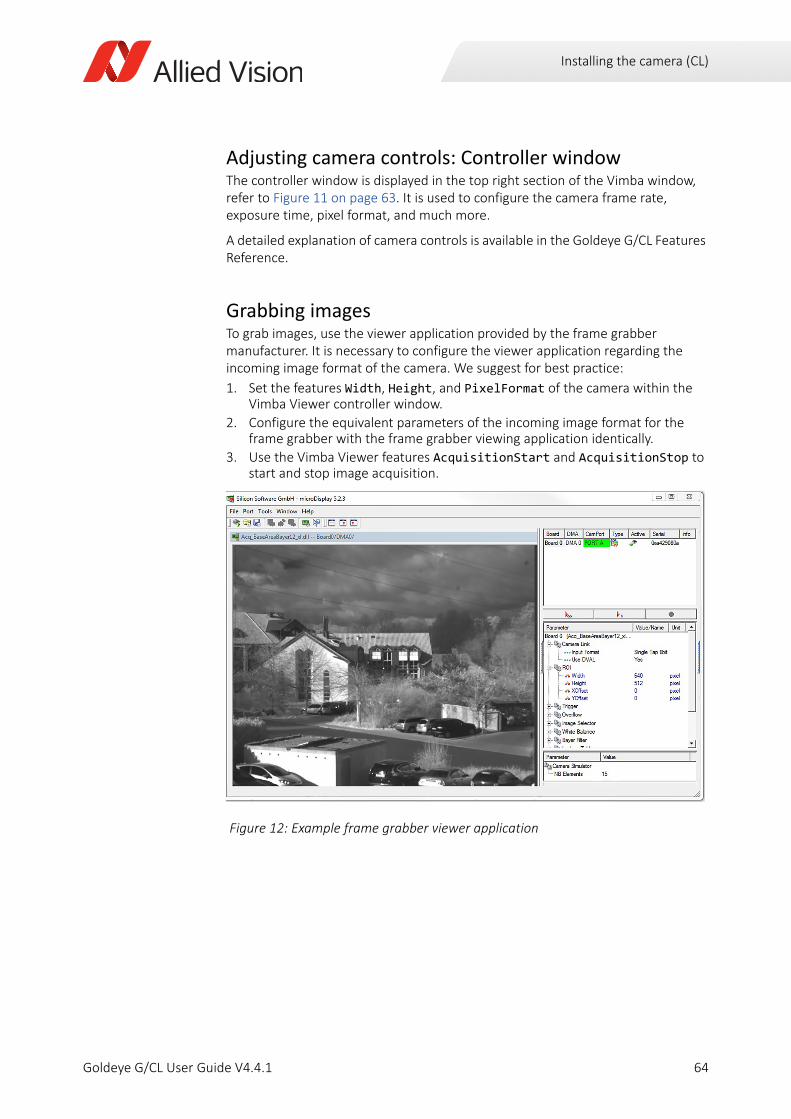
Installing the camera (CL)
Adjusting camera controls: Controller windowThe controller window is displayed in the top right section of the Vimba window, refer to Figure 11 on page 63. It is used to configure the camera frame rate, exposure time, pixel format, and much more.
A detailed explanation of camera controls is available in the Goldeye G/CL Features Reference.
Grabbing imagesTo grab images, use the viewer application provided by the frame grabber manufacturer. It is necessary to configure the viewer application regarding the incoming image format of the camera. We suggest for best practice:
1. Set the features Width, Height, and PixelFormat of the camera within the Vimba Viewer controller window.
2. Configure the equivalent parameters of the incoming image format for the frame grabber with the frame grabber viewing application identically.
3. Use the Vimba Viewer features AcquisitionStart and AcquisitionStop to start and stop image acquisition.
Figure 12: Example frame grabber viewer application
64Goldeye G/CL User Guide V4.4.1
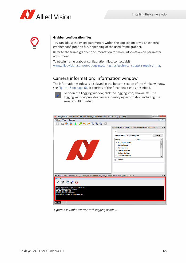
Installing the camera (CL)
Camera information: Information windowThe information window is displayed in the bottom section of the Vimba window, see Figure 15 on page 66. It consists of the functionalities as described.
Grabber configuration files
You can adjust the image parameters within the application or via an external grabber configuration file, depending of the used frame grabber.
Refer to the frame grabber documentation for more information on parameter adjustment.
To obtain frame grabber configuration files, contact visit www.alliedvision.com/en/about-us/contact-us/technical-support-repair-/-rma.
To open the Logging window, click the logging icon, shown left. The logging window provides camera identifying information including the serial and ID number.
Figure 13: Vimba Viewer with logging window
65Goldeye G/CL User Guide V4.4.1
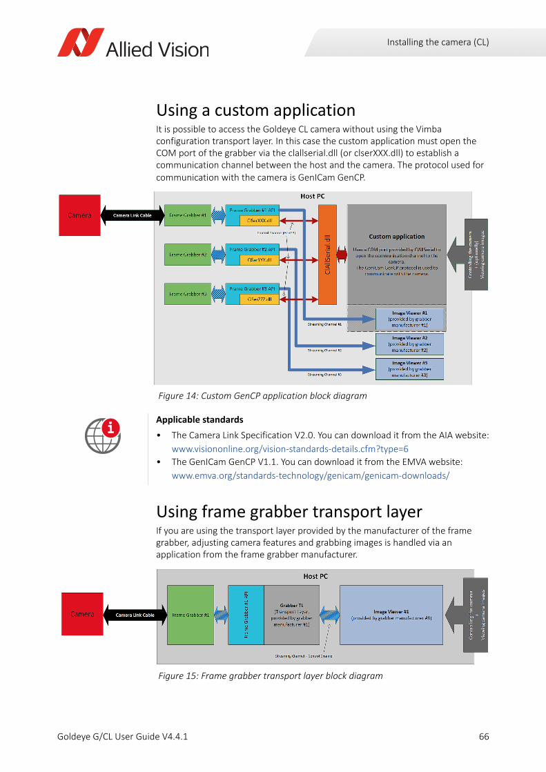
Installing the camera (CL)
Using a custom applicationIt is possible to access the Goldeye CL camera without using the Vimba configuration transport layer. In this case the custom application must open the COM port of the grabber via the clallserial.dll (or clserXXX.dll) to establish a communication channel between the host and the camera. The protocol used for communication with the camera is GenICam GenCP.
Using frame grabber transport layerIf you are using the transport layer provided by the manufacturer of the frame grabber, adjusting camera features and grabbing images is handled via an application from the frame grabber manufacturer.
Figure 14: Custom GenCP application block diagram
Applicable standards
• The Camera Link Specification V2.0. You can download it from the AIA website:
www.visiononline.org/vision-standards-details.cfm?type=6
• The GenICam GenCP V1.1. You can download it from the EMVA website:
www.emva.org/standards-technology/genicam/genicam-downloads/
Figure 15: Frame grabber transport layer block diagram
i
66Goldeye G/CL User Guide V4.4.1
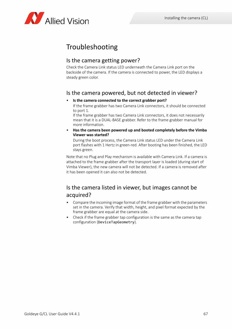
Installing the camera (CL)
Troubleshooting
Is the camera getting power?Check the Camera Link status LED underneath the Camera Link port on the backside of the camera. If the camera is connected to power, the LED displays a steady green color.
Is the camera powered, but not detected in viewer?• Is the camera connected to the correct grabber port?
If the frame grabber has two Camera Link connectors, it should be connected to port 1. If the frame grabber has two Camera Link connectors, it does not necessarily mean that it is a DUAL-BASE grabber. Refer to the frame grabber manual for more information.
• Has the camera been powered up and booted completely before the Vimba Viewer was started?
During the boot process, the Camera Link status LED under the Camera Link port flashes with 1 Hertz in green-red. After booting has been finished, the LED stays green.
Note that no Plug and Play mechanism is available with Camera Link. If a camera is attached to the frame grabber after the transport layer is loaded (during start of Vimba Viewer), the new camera will not be detected. If a camera is removed after it has been opened it can also not be detected.
Is the camera listed in viewer, but images cannot be acquired?• Compare the incoming image format of the frame grabber with the parameters
set in the camera. Verify that width, height, and pixel format expected by the frame grabber are equal at the camera side.
• Check if the frame grabber tap configuration is the same as the camera tap configuration (DeviceTapGeometry).
67Goldeye G/CL User Guide V4.4.1
Specifications
Goldeye G/CL User Guide V4.4.1
This chapter includes:
Model naming ....................................................................... 69Applied standards ................................................................. 71Maximum and ROI frame rates............................................. 74Specifications (GigE models)................................................. 75Specifications (CL models) .................................................. 112Camera dimensions (GigE models) ..................................... 157Camera dimensions (CL models) ........................................ 168Sensor position accuracy .................................................... 177
68
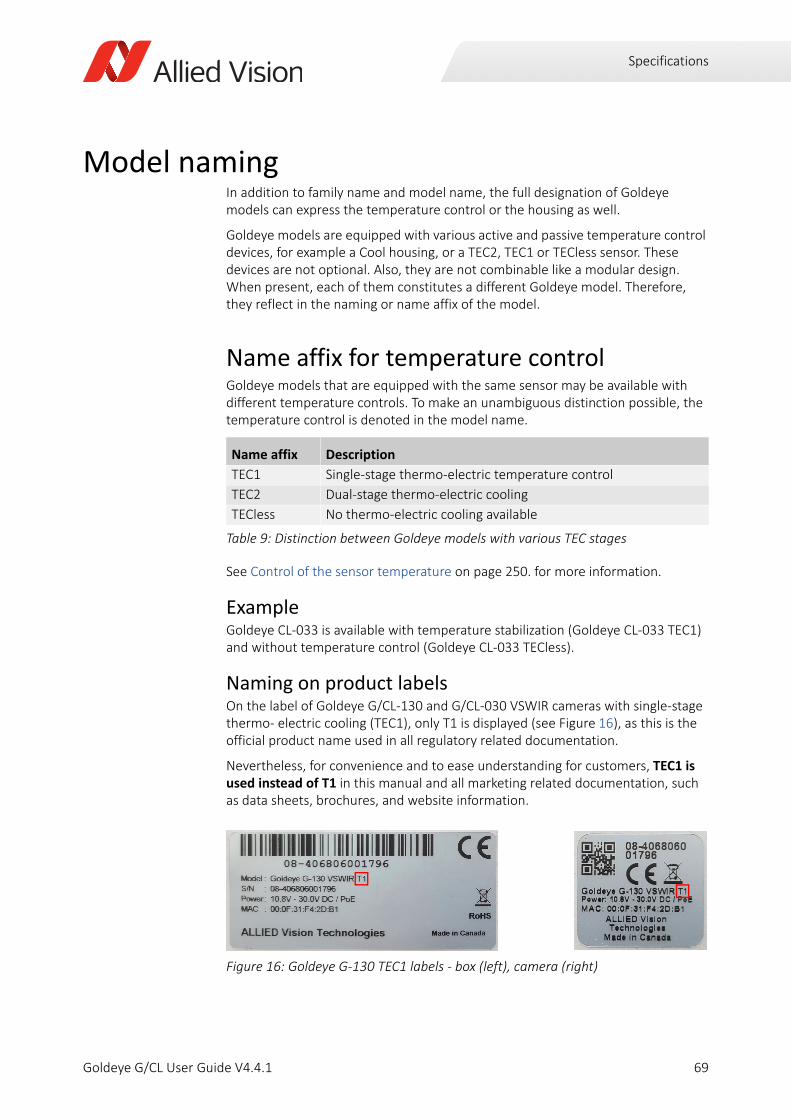
Specifications
Model namingIn addition to family name and model name, the full designation of Goldeye models can express the temperature control or the housing as well.
Goldeye models are equipped with various active and passive temperature control devices, for example a Cool housing, or a TEC2, TEC1 or TECless sensor. These devices are not optional. Also, they are not combinable like a modular design. When present, each of them constitutes a different Goldeye model. Therefore, they reflect in the naming or name affix of the model.
Name affix for temperature controlGoldeye models that are equipped with the same sensor may be available with different temperature controls. To make an unambiguous distinction possible, the temperature control is denoted in the model name.
See Control of the sensor temperature on page 250. for more information.
ExampleGoldeye CL-033 is available with temperature stabilization (Goldeye CL-033 TEC1) and without temperature control (Goldeye CL-033 TECless).
Naming on product labelsOn the label of Goldeye G/CL-130 and G/CL-030 VSWIR cameras with single-stage thermo- electric cooling (TEC1), only T1 is displayed (see Figure 16), as this is the official product name used in all regulatory related documentation.
Nevertheless, for convenience and to ease understanding for customers, TEC1 is used instead of T1 in this manual and all marketing related documentation, such as data sheets, brochures, and website information.
Name affix Description
TEC1 Single-stage thermo-electric temperature control
TEC2 Dual-stage thermo-electric cooling
TECless No thermo-electric cooling available
Table 9: Distinction between Goldeye models with various TEC stages
Figure 16: Goldeye G-130 TEC1 labels - box (left), camera (right)
69Goldeye G/CL User Guide V4.4.1
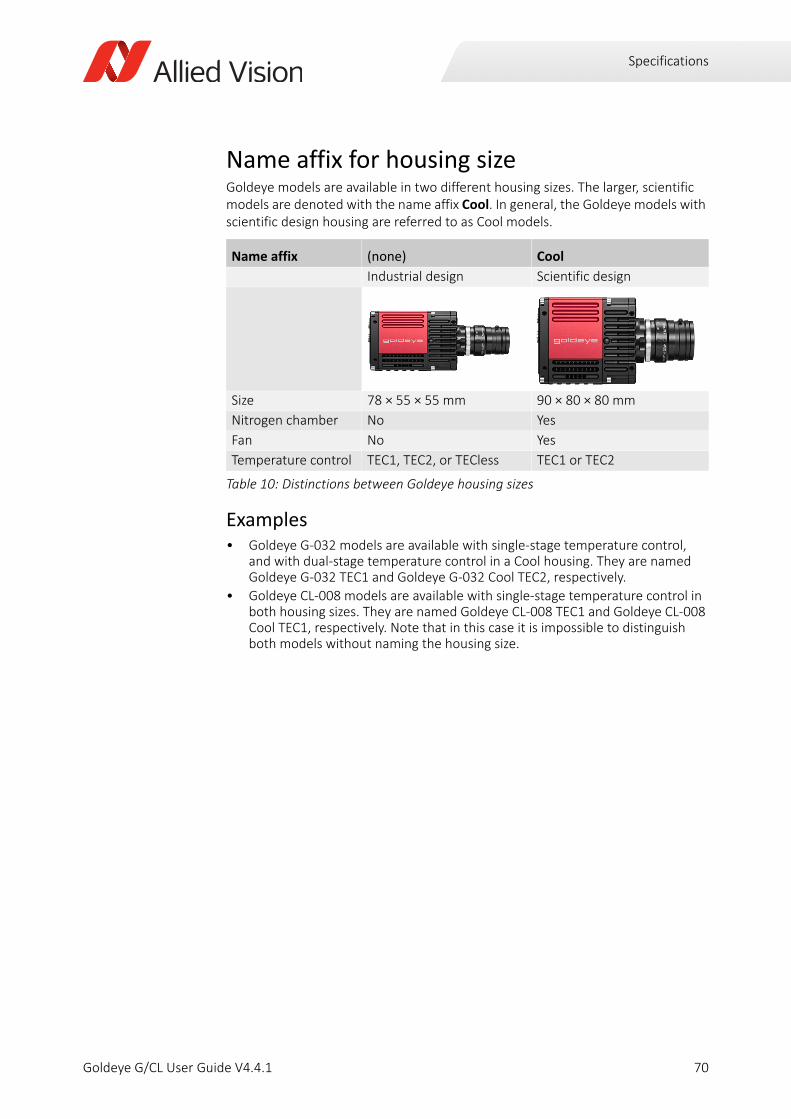
Specifications
Name affix for housing sizeGoldeye models are available in two different housing sizes. The larger, scientific models are denoted with the name affix Cool. In general, the Goldeye models with scientific design housing are referred to as Cool models.
Examples• Goldeye G-032 models are available with single-stage temperature control,
and with dual-stage temperature control in a Cool housing. They are named Goldeye G-032 TEC1 and Goldeye G-032 Cool TEC2, respectively.
• Goldeye CL-008 models are available with single-stage temperature control in both housing sizes. They are named Goldeye CL-008 TEC1 and Goldeye CL-008 Cool TEC1, respectively. Note that in this case it is impossible to distinguish both models without naming the housing size.
Name affix (none) Cool
Industrial design Scientific design
Size 78 × 55 × 55 mm 90 × 80 × 80 mm
Nitrogen chamber No Yes
Fan No Yes
Temperature control TEC1, TEC2, or TECless TEC1 or TEC2
Table 10: Distinctions between Goldeye housing sizes
70Goldeye G/CL User Guide V4.4.1
Specifications
Applied standards
Camera Link standard (CL models)Camera Link is a communication interface for vision applications that reduces time and costs necessary for support. Goldeye CL cameras are compliant with the Camera Link V2.0 standard. Goldeye CL cameras work with standard frame grabbers and cables.
GenICamGenICam is the command structure for the GigE Vision camera control. GenICam is administered by the European Machine Vision Association.
GenICam establishes a common camera control interface so that third-party software can communicate with cameras from various manufacturers without customization. It is incorporated as part of the GigE Vision standard.
GenCPThe camera is to be controlled using the GenICam GenCP Generic Control Protocol. GenCP is packet based and it uses a virtual 64-bit address space that contains all control registers of the camera.
GigE Vision (GigE models)GigE Vision is an interface standard for digital machine vision cameras, developed and maintained by the Automated Imaging Association. It is built on the Gigabit Ethernet communication protocol and widely supported in the industrial imaging industry.
IP classEquipped with a lens as intended, Goldeye G/CL cameras comply with
• IP40 class for all cameras except Cool models
• IP20 class for Cool models only
according to IEC 60529.
In the following, a short introduction to GenCP will be given, however it is recommended to also refer to the standard which can be downloaded here:
www.emva.org/wp-content/uploads/GenCP_1.1.pdf
i
71Goldeye G/CL User Guide V4.4.1
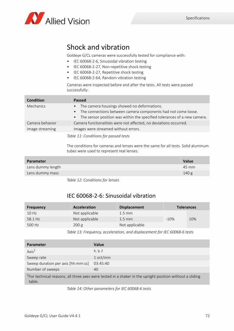
Specifications
Shock and vibrationGoldeye G/CL cameras were successfully tested for compliance with:
• IEC 60068-2-6, Sinusoidal vibration testing
• IEC 60068-2-27, Non-repetitive shock testing
• IEC 60068-2-27, Repetitive shock testing
• IEC 60068-2-64, Random vibration testing
Cameras were inspected before and after the tests. All tests were passed successfully:
The conditions for cameras and lenses were the same for all tests. Solid aluminum tubes were used to represent real lenses:
IEC 60068-2-6: Sinusoidal vibration
Condition Passed
Mechanics • The camera housings showed no deformations.
• The connections between camera components had not come loose.
• The sensor position was within the specified tolerances of a new camera.
Camera behavior Camera functionalities were not affected, no deviations occurred.
Image streaming Images were streamed without errors.
Table 11: Conditions for passed tests
Parameter Value
Lens dummy length 45 mm
Lens dummy mass 140 g
Table 12: Conditions for lenses
Frequency Acceleration Displacement Tolerances
10 Hz Not applicable 1.5 mm
-10% 10%58.1 Hz Not applicable 1.5 mm
500 Hz 200 g Not applicable
Table 13: Frequency, acceleration, and displacement for IEC 60068-6 tests
Parameter Value
Axis1 x, y, z
Sweep rate 1 oct/min
Sweep duration per axis [hh:mm:ss] 03:45:40
Number of sweeps 401For technical reasons, all three axes were tested in a shaker in the upright position without a sliding table.
Table 14: Other parameters for IEC 60068-6 tests
72Goldeye G/CL User Guide V4.4.1
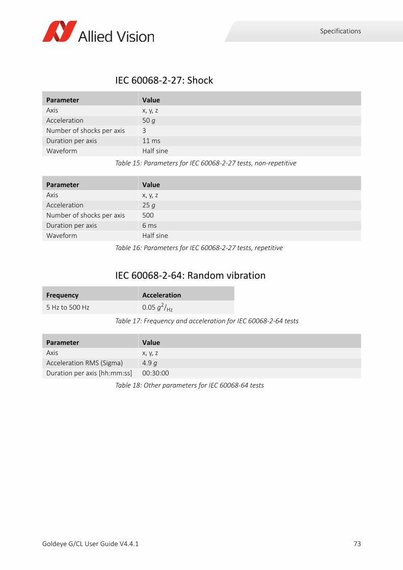
Specifications
IEC 60068-2-27: Shock
IEC 60068-2-64: Random vibration
Parameter Value
Axis x, y, z
Acceleration 50 g
Number of shocks per axis 3
Duration per axis 11 ms
Waveform Half sine
Table 15: Parameters for IEC 60068-2-27 tests, non-repetitive
Parameter Value
Axis x, y, z
Acceleration 25 g
Number of shocks per axis 500
Duration per axis 6 ms
Waveform Half sine
Table 16: Parameters for IEC 60068-2-27 tests, repetitive
Frequency Acceleration
5 Hz to 500 Hz 0.05 g2/Hz
Table 17: Frequency and acceleration for IEC 60068-2-64 tests
Parameter Value
Axis x, y, z
Acceleration RMS (Sigma) 4.9 g
Duration per axis [hh:mm:ss] 00:30:00
Table 18: Other parameters for IEC 60068-64 tests
73Goldeye G/CL User Guide V4.4.1
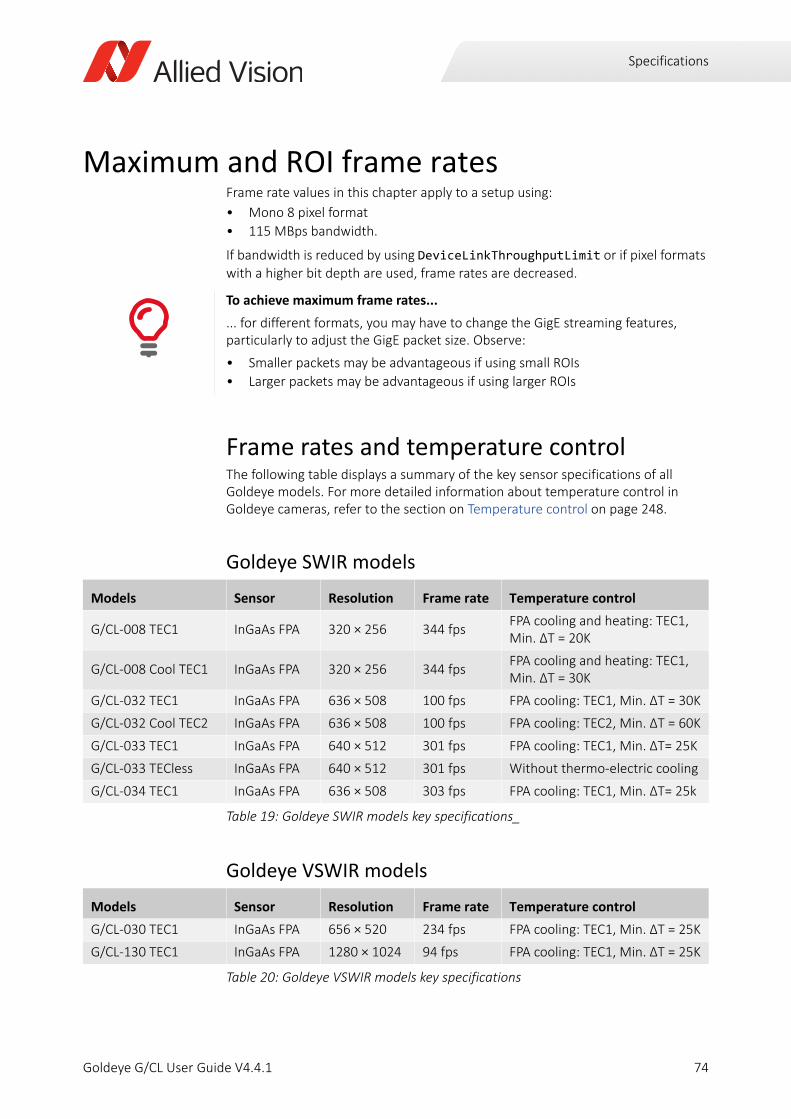
Specifications
Maximum and ROI frame ratesFrame rate values in this chapter apply to a setup using:
• Mono 8 pixel format
• 115 MBps bandwidth.
If bandwidth is reduced by using DeviceLinkThroughputLimit or if pixel formats with a higher bit depth are used, frame rates are decreased.
Frame rates and temperature controlThe following table displays a summary of the key sensor specifications of all Goldeye models. For more detailed information about temperature control in Goldeye cameras, refer to the section on Temperature control on page 248.
Goldeye SWIR models
Goldeye VSWIR models
To achieve maximum frame rates...
... for different formats, you may have to change the GigE streaming features, particularly to adjust the GigE packet size. Observe:
• Smaller packets may be advantageous if using small ROIs
• Larger packets may be advantageous if using larger ROIs
Models Sensor Resolution Frame rate Temperature control
G/CL-008 TEC1 InGaAs FPA 320 × 256 344 fpsFPA cooling and heating: TEC1, Min. ΔT = 20K
G/CL-008 Cool TEC1 InGaAs FPA 320 × 256 344 fpsFPA cooling and heating: TEC1, Min. ΔT = 30K
G/CL-032 TEC1 InGaAs FPA 636 × 508 100 fps FPA cooling: TEC1, Min. ΔT = 30K
G/CL-032 Cool TEC2 InGaAs FPA 636 × 508 100 fps FPA cooling: TEC2, Min. ΔT = 60K
G/CL-033 TEC1 InGaAs FPA 640 × 512 301 fps FPA cooling: TEC1, Min. ΔT= 25K
G/CL-033 TECless InGaAs FPA 640 × 512 301 fps Without thermo-electric cooling
G/CL-034 TEC1 InGaAs FPA 636 × 508 303 fps FPA cooling: TEC1, Min. ΔT= 25k
Table 19: Goldeye SWIR models key specifications_
Models Sensor Resolution Frame rate Temperature control
G/CL-030 TEC1 InGaAs FPA 656 × 520 234 fps FPA cooling: TEC1, Min. ΔT = 25K
G/CL-130 TEC1 InGaAs FPA 1280 × 1024 94 fps FPA cooling: TEC1, Min. ΔT = 25K
Table 20: Goldeye VSWIR models key specifications
74Goldeye G/CL User Guide V4.4.1
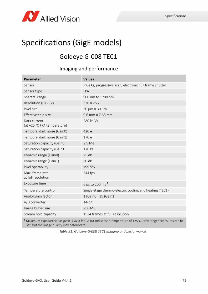
Specifications
Specifications (GigE models)
Goldeye G-008 TEC1
Imaging and performance
Parameter Values
Sensor InGaAs, progressive scan, electronic full frame shutter
Sensor type FPA
Spectral range 900 nm to 1700 nm
Resolution (H) × (V) 320 × 256
Pixel size 30 μm × 30 μm
Effective chip size 9.6 mm × 7.68 mm
Dark current (at +25 °C FPA temperature)
280 ke¯/s
Temporal dark noise (Gain0) 420 e¯
Temporal dark noise (Gain1) 170 e¯
Saturation capacity (Gain0) 2.5 Me¯
Saturation capacity (Gain1) 170 ke¯
Dynamic range (Gain0) 75 dB
Dynamic range (Gain1) 60 dB
Pixel operability >99.5%
Max. frame rate at full resolution
344 fps
Exposure time 6 µs to 200 ms 1
Temperature control Single-stage thermo-electric cooling and heating (TEC1)
Analog gain factor 1 (Gain0), 15 (Gain1)
A/D converter 14-bit
Image buffer size 256 MB
Stream hold capacity 1524 frames at full resolution
1 Maximum exposure value given is valid for Gain0 and sensor temperature of +25°C. Even longer exposures can be set, but the image quality may deteriorate.
Table 21: Goldeye G-008 TEC1 imaging and performance
75Goldeye G/CL User Guide V4.4.1

Specifications
Output
GPIOs
Mechanics
Parameter Values
Digital interface GigE Vision (based on IEEE 802.3 1000BASE-T)
Bit depth 8-bit, 12-bit, 14-bit
Pixel formats Mono 8, Mono 12, Mono 12Packed, Mono 14
Table 22: Goldeye G-008 TEC1 output
Parameter Values
Opto-isolated I/Os 1 input, 2 outputs
RS232 up to 115,200 bits per second, 8N1 (adjustable)
LVTTL I/Os 1 input, 1 output
Table 23: Goldeye G-008 TEC1 GPIOs
Parameter Values
Body dimensions (L × W × H)without lens adapter
78 × 55 × 55 mm
Lens mounts C-Mount, F-Mount, M42-Mount
Mass, body only, without adapter 320 g
Mass, with C-Mount adapter 340 g
Mass, with F-Mount adapter 390 g
Mass, with M42-Mount adapter 360 g
Table 24: Goldeye G-008 TEC1 mechanics
76Goldeye G/CL User Guide V4.4.1
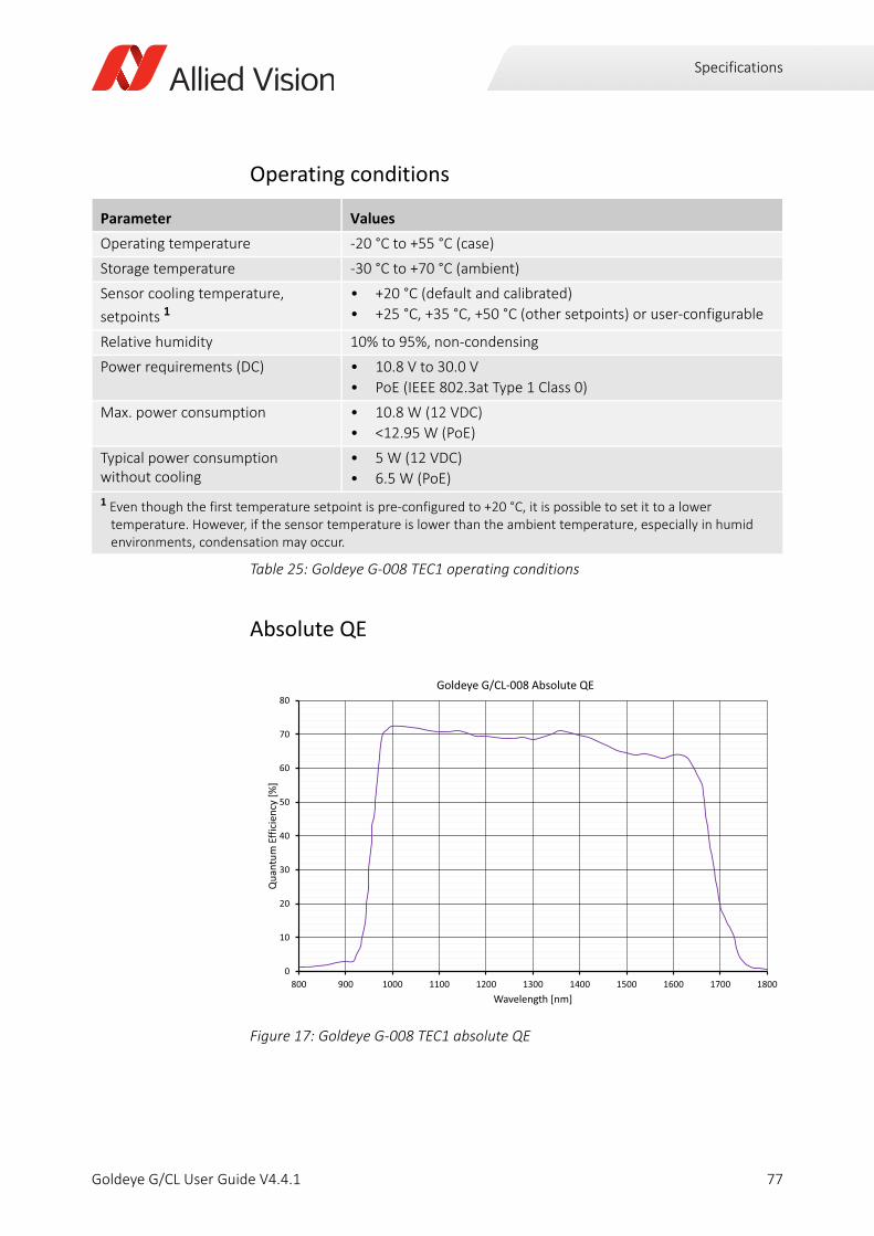
Specifications
Operating conditions
Absolute QE
Parameter Values
Operating temperature -20 °C to +55 °C (case)
Storage temperature -30 °C to +70 °C (ambient)
Sensor cooling temperature,
setpoints 1• +20 °C (default and calibrated)
• +25 °C, +35 °C, +50 °C (other setpoints) or user-configurable
Relative humidity 10% to 95%, non-condensing
Power requirements (DC) • 10.8 V to 30.0 V
• PoE (IEEE 802.3at Type 1 Class 0)
Max. power consumption • 10.8 W (12 VDC)
• <12.95 W (PoE)
Typical power consumption without cooling
• 5 W (12 VDC)
• 6.5 W (PoE)
1 Even though the first temperature setpoint is pre-configured to +20 °C, it is possible to set it to a lower temperature. However, if the sensor temperature is lower than the ambient temperature, especially in humid environments, condensation may occur.
Table 25: Goldeye G-008 TEC1 operating conditions
Figure 17: Goldeye G-008 TEC1 absolute QE
0
10
20
30
40
50
60
70
80
800 900 1000 1100 1200 1300 1400 1500 1600 1700 1800
Qua
ntum
Effic
ienc
y[%
]
Wavelength [nm]
Goldeye G/CL 008 Absolute QE
77Goldeye G/CL User Guide V4.4.1
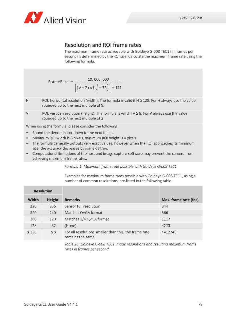
Specifications
Resolution and ROI frame ratesThe maximum frame rate achievable with Goldeye G-008 TEC1 (in frames per second) is determined by the ROI size. Calculate the maximum frame rate using the following formula.
Examples for maximum frame rates possible with Goldeye G-008 TEC1, using a number of common resolutions, are listed in the following table.
H ROI: horizontal resolution (width). The formula is valid if H ≥ 128. For H always use the value rounded up to the next multiple of 8.
V ROI: vertical resolution (height). The formula is valid if V ≥ 8. For V always use the value rounded up to the next multiple of 2.
When using the formula, please consider the following:
• Round the denominator down to the next full µs.
• Minimum ROI width is 8 pixels, minimum ROI height is 4 pixels.
• The formula generally outputs very exact values, however when the ROI approaches its minimum size, the accuracy decreases by some degree.
• Computational limitations of the host and image capture software may prevent the camera from achieving maximum frame rates.
Formula 1: Maximum frame rate possible with Goldeye G-008 TEC1
Resolution
Remarks Max. frame rate [fps]Width Height
320 256 Sensor full resolution 344
320 240 Matches QVGA format 366
160 120 Matches 1/4 QVGA format 1117
128 32 (None) 4273
≤ 128 ≤ 8 For all resolutions smaller than this, the frame rate remains the same.
>=12345
Table 26: Goldeye G-008 TEC1 image resolutions and resulting maximum frame rates in frames per second
FrameRate10 000 000, ,
V 2+ H4---- 32+ 171+
------------------------------------------------------------------------=
78Goldeye G/CL User Guide V4.4.1
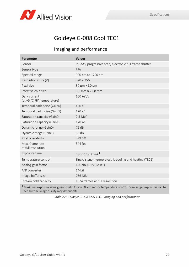
Specifications
Goldeye G-008 Cool TEC1
Imaging and performance
Parameter Values
Sensor InGaAs, progressive scan, electronic full frame shutter
Sensor type FPA
Spectral range 900 nm to 1700 nm
Resolution (H) × (V) 320 × 256
Pixel size 30 μm × 30 μm
Effective chip size 9.6 mm × 7.68 mm
Dark current (at +5 °C FPA temperature)
160 ke¯/s
Temporal dark noise (Gain0) 420 e¯
Temporal dark noise (Gain1) 170 e¯
Saturation capacity (Gain0) 2.5 Me¯
Saturation capacity (Gain1) 170 ke¯
Dynamic range (Gain0) 75 dB
Dynamic range (Gain1) 60 dB
Pixel operability >99.5%
Max. frame rate at full resolution
344 fps
Exposure time 6 µs to 1250 ms 1
Temperature control Single-stage thermo-electric cooling and heating (TEC1)
Analog gain factor 1 (Gain0), 15 (Gain1)
A/D converter 14-bit
Image buffer size 256 MB
Stream hold capacity 1524 frames at full resolution
1 Maximum exposure value given is valid for Gain0 and sensor temperature of +5°C. Even longer exposures can be set, but the image quality may deteriorate.
Table 27: Goldeye G-008 Cool TEC1 imaging and performance
79Goldeye G/CL User Guide V4.4.1
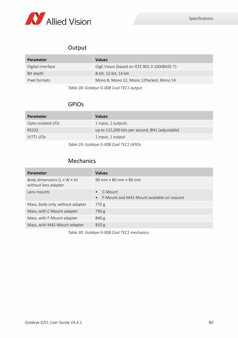
Specifications
Output
GPIOs
Mechanics
Parameter Values
Digital interface GigE Vision (based on IEEE 802.3 1000BASE-T)
Bit depth 8-bit, 12-bit, 14-bit
Pixel formats Mono 8, Mono 12, Mono 12Packed, Mono 14
Table 28: Goldeye G-008 Cool TEC1 output
Parameter Values
Opto-isolated I/Os 1 input, 2 outputs
RS232 up to 115,200 bits per second, 8N1 (adjustable)
LVTTL I/Os 1 input, 1 output
Table 29: Goldeye G-008 Cool TEC1 GPIOs
Parameter Values
Body dimensions (L × W × H)without lens adapter
90 mm × 80 mm × 80 mm
Lens mounts • C-Mount
• F-Mount and M42-Mount available on request
Mass, body only, without adapter 770 g
Mass, with C-Mount adapter 790 g
Mass, with F-Mount adapter 840 g
Mass, with M42-Mount adapter 810 g
Table 30: Goldeye G-008 Cool TEC1 mechanics
80Goldeye G/CL User Guide V4.4.1

Specifications
Operating conditions
Absolute QE
Parameter Values
Operating temperature -20 °C to +55 °C (case)
Storage temperature -30 °C to +70 °C (ambient)
Sensor cooling temperature, setpoints
• +5 °C (default and calibrated)
• -5 °C, +10 °C, +20 °C (other setpoints) or user-configurable
Relative humidity 10% to 95%, non-condensing
Power requirements (DC) • 10.8 V to 30.0 V
• PoE (IEEE 802.3at Type 1 Class 0)
Max. power consumption • 10.7 W (12 VDC)
• <12.95 W (PoE)
Typical power consumption without cooling
• 4.9 W (12 VDC)
• 6.6 W (PoE)
Table 31: Goldeye G-008 Cool TEC1 operating conditions
Figure 18: Goldeye G-008 Cool TEC1 absolute QE
0
10
20
30
40
50
60
70
80
800 900 1000 1100 1200 1300 1400 1500 1600 1700 1800
Qua
ntum
Effic
ienc
y[%
]
Wavelength [nm]
Goldeye G/CL 008 Absolute QE
81Goldeye G/CL User Guide V4.4.1
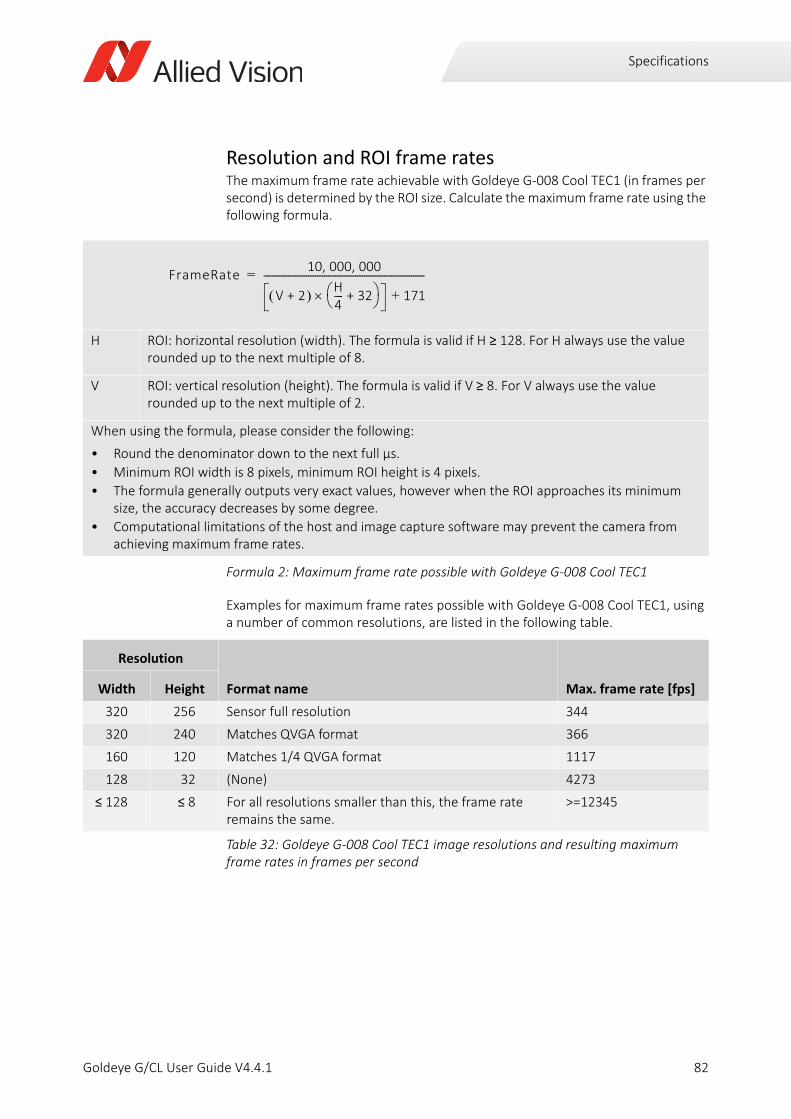
Specifications
Resolution and ROI frame ratesThe maximum frame rate achievable with Goldeye G-008 Cool TEC1 (in frames per second) is determined by the ROI size. Calculate the maximum frame rate using the following formula.
Examples for maximum frame rates possible with Goldeye G-008 Cool TEC1, using a number of common resolutions, are listed in the following table.
H ROI: horizontal resolution (width). The formula is valid if H ≥ 128. For H always use the value rounded up to the next multiple of 8.
V ROI: vertical resolution (height). The formula is valid if V ≥ 8. For V always use the value rounded up to the next multiple of 2.
When using the formula, please consider the following:
• Round the denominator down to the next full µs.
• Minimum ROI width is 8 pixels, minimum ROI height is 4 pixels.
• The formula generally outputs very exact values, however when the ROI approaches its minimum size, the accuracy decreases by some degree.
• Computational limitations of the host and image capture software may prevent the camera from achieving maximum frame rates.
Formula 2: Maximum frame rate possible with Goldeye G-008 Cool TEC1
Resolution
Format name Max. frame rate [fps]Width Height
320 256 Sensor full resolution 344
320 240 Matches QVGA format 366
160 120 Matches 1/4 QVGA format 1117
128 32 (None) 4273
≤ 128 ≤ 8 For all resolutions smaller than this, the frame rate remains the same.
>=12345
Table 32: Goldeye G-008 Cool TEC1 image resolutions and resulting maximum frame rates in frames per second
FrameRate10 000 000, ,
V 2+ H4---- 32+ 171+
------------------------------------------------------------------------=
82Goldeye G/CL User Guide V4.4.1

Specifications
Goldeye G-030 TEC1
Imaging and performance
Parameter Values
Sensor model Sony IMX991 SenSWIR
Sensor type InGaAs
Sensor format Type 1/4 (4.1 mm diagonal)
Shutter type Global shutter
Spectral range 400 nm to 1700 nm
Resolution 656 (H) × 520 (V)
Pixel size 5 μm × 5 μm
Effective chip size 3.28 mm × 2.6 mm
Dark current (at +20 °C FPA temperature)
4.8 ke¯/s
Temporal dark noise (0 dB) 250 e¯
Temporal dark noise (18 dB) 210 e¯
Saturation capacity (0 dB) 165 ke¯
Saturation capacity (18 dB) 17.2 ke¯
Dynamic range (0 dB) 56.4 dB
Dynamic range (18 dB) 38.2 dB
Pixel operability >99.5%
Exposure time 16 µs to 200 ms 1
Max. frame rate at full resolution 234 fps
Temperature control Single-stage thermo-electric cooling (TEC1)
Analog gain factor 1 (0 dB), 7.9 (18 dB)
A/D converter 12-bit
Image buffer size 256 MB
Stream hold capacity 370 frames at full resolution
1 Maximum exposure value given is valid for 0 dB and sensor temperature of +20°C. Even longer exposures can be set, but the image quality may deteriorate.
Table 33: Goldeye G-030 TEC1 imaging and performance
83Goldeye G/CL User Guide V4.4.1
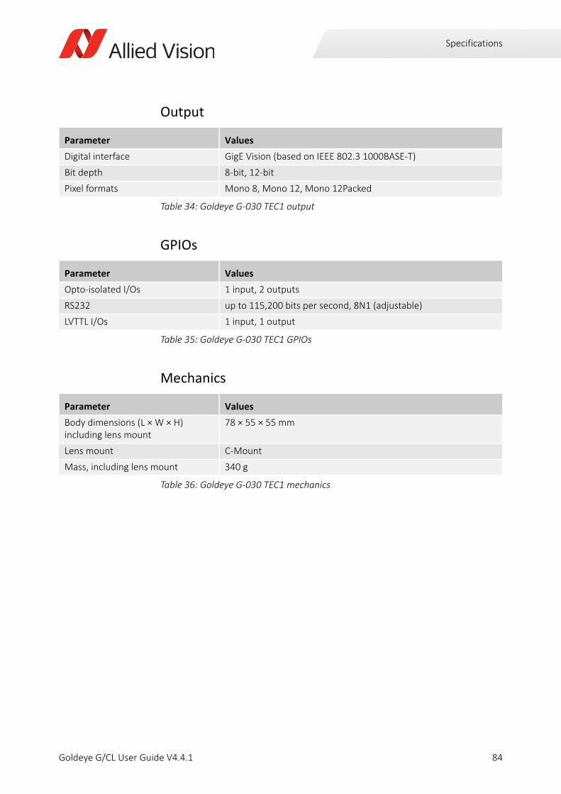
Specifications
Output
GPIOs
Mechanics
Parameter Values
Digital interface GigE Vision (based on IEEE 802.3 1000BASE-T)
Bit depth 8-bit, 12-bit
Pixel formats Mono 8, Mono 12, Mono 12Packed
Table 34: Goldeye G-030 TEC1 output
Parameter Values
Opto-isolated I/Os 1 input, 2 outputs
RS232 up to 115,200 bits per second, 8N1 (adjustable)
LVTTL I/Os 1 input, 1 output
Table 35: Goldeye G-030 TEC1 GPIOs
Parameter Values
Body dimensions (L × W × H)including lens mount
78 × 55 × 55 mm
Lens mount C-Mount
Mass, including lens mount 340 g
Table 36: Goldeye G-030 TEC1 mechanics
84Goldeye G/CL User Guide V4.4.1
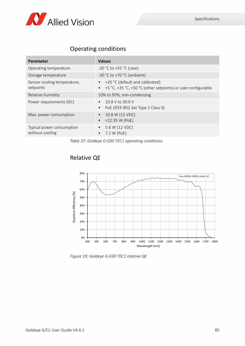
Specifications
Operating conditions
Relative QE
Parameter Values
Operating temperature -20 °C to +55 °C (case)
Storage temperature -30 °C to +70 °C (ambient)
Sensor cooling temperature, setpoints
• +20 °C (default and calibrated)
• +5 °C, +35 °C, +50 °C (other setpoints) or user-configurable
Relative humidity 10% to 95%, non-condensing
Power requirements (DC) • 10.8 V to 30.0 V
• PoE (IEEE 802.3at Type 1 Class 0)
Max. power consumption • 10.8 W (12 VDC)
• <12.95 W (PoE)
Typical power consumption without cooling
• 5.6 W (12 VDC)
• 7.2 W (PoE)
Table 37: Goldeye G-030 TEC1 operating conditions
Figure 19: Goldeye G-030 TEC1 relative QE
0%
10%
20%
30%
40%
50%
60%
70%
80%
400 500 600 700 800 900 1000 1100 1200 1300 1400 1500 1600 1700 1800
Qua
ntum
Eci
ency
[%]
Wavelength [nm]
Sony IMX990, IMX991 QE
85Goldeye G/CL User Guide V4.4.1
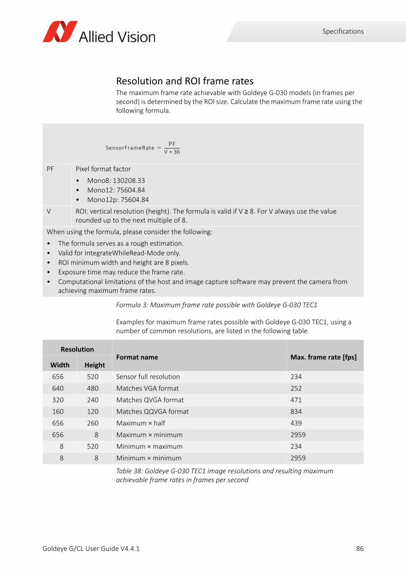
Specifications
Resolution and ROI frame ratesThe maximum frame rate achievable with Goldeye G-030 models (in frames per second) is determined by the ROI size. Calculate the maximum frame rate using the following formula.
Examples for maximum frame rates possible with Goldeye G-030 TEC1, using a number of common resolutions, are listed in the following table.
PF Pixel format factor
• Mono8: 130208.33
• Mono12: 75604.84
• Mono12p: 75604.84
V ROI: vertical resolution (height). The formula is valid if V ≥ 8. For V always use the value rounded up to the next multiple of 8.
When using the formula, please consider the following:
• The formula serves as a rough estimation.
• Valid for IntegrateWhileRead-Mode only.
• ROI minimum width and height are 8 pixels.
• Exposure time may reduce the frame rate.
• Computational limitations of the host and image capture software may prevent the camera from achieving maximum frame rates.
Formula 3: Maximum frame rate possible with Goldeye G-030 TEC1
ResolutionFormat name Max. frame rate [fps]
Width Height
656 520 Sensor full resolution 234
640 480 Matches VGA format 252
320 240 Matches QVGA format 471
160 120 Matches QQVGA format 834
656 260 Maximum × half 439
656 8 Maximum × minimum 2959
8 520 Minimum × maximum 234
8 8 Minimum × minimum 2959
Table 38: Goldeye G-030 TEC1 image resolutions and resulting maximum achievable frame rates in frames per second
SensorFrameRatePF
V 36+----------------=
86Goldeye G/CL User Guide V4.4.1

Specifications
Goldeye G-032 TEC1
Imaging and performance
Parameter Values
Sensor InGaAs, progressive scan, electronic full frame shutter
Sensor type FPA
Spectral range 900 nm to 1700 nm
Resolution (H) × (V) 636 × 508
Pixel size 25 μm × 25 μm
Effective chip size 15.9 mm × 12.7 mm
Dark current (at +20 °C FPA temperature)
380 ke¯/s
Temporal dark noise (Gain0) 400 e¯
Temporal dark noise (Gain1) 170 e¯
Saturation capacity (Gain0) 1.9 Me¯
Saturation capacity (Gain1) 39 ke¯
Dynamic range (Gain0) 73 dB
Dynamic range (Gain1) 47 dB
Pixel operability >99.5%
Exposure time 6 µs to 200 ms 1
Max. frame rate at full resolution
100 fps
Temperature control Single-stage thermo-electric cooling (TEC1)
Analog gain factor 1 (Gain0), 50 (Gain1)
A/D converter 14-bit
Image buffer size 256 MB
Stream hold capacity 397 frames at full resolution
1 Maximum exposure value given is valid for Gain0 and sensor temperature of +25°C. Even longer exposures can be set, but the image quality may deteriorate.
Table 39: Goldeye G-032 TEC1 imaging and performance
87Goldeye G/CL User Guide V4.4.1

Specifications
Output
GPIOs
Mechanics
Parameter Values
Digital interface GigE Vision (based on IEEE 802.3 1000BASE-T)
Bit depth 8-bit, 12-bit, 14-bit
Pixel formats Mono 8, Mono 12, Mono 12Packed, Mono 14
Table 40: Goldeye G-032 TEC1 output
Parameter Values
Opto-isolated I/Os 1 input, 2 outputs
RS232 up to 115,200 bits per second, 8N1 (adjustable)
LVTTL I/Os 1 input, 1 output
Table 41: Goldeye G-032 TEC1 GPIOs
Parameter Values
Body dimensions (L × W × H)without lens adapter
78 mm × 55 mm × 55 mm
Lens mounts C-Mount, F-Mount, M42-Mount
Mass, body only, without adapter 350 g
Mass, with C-Mount adapter 370 g
Mass, with F-Mount adapter 420 g
Mass, with M42-Mount adapter 390 g
Table 42: Goldeye G-032 TEC1 mechanics
88Goldeye G/CL User Guide V4.4.1

Specifications
Operating conditions
Absolute QE
Parameter Values
Operating temperature -20 °C to +55 °C (case)
Storage temperature -30 °C to +70 °C (ambient)
Sensor cooling temperature, setpoints
• +20 °C (default and calibrated)
• +5 °C, +35 °C, +50 °C (other setpoints) or user-configurable
Relative humidity 10% to 95%, non-condensing
Power requirements (DC) • 10.8 V to 30.0 V
• PoE (IEEE 802.3at Type 1 Class 0)
Max. power consumption • 10.8 W (12 VDC)
• <12.95 W (PoE)
Typical power consumption without cooling
• 5 W (12 VDC)
• 6.5 W (PoE)
Table 43: Goldeye G-032 TEC1 operating conditions
Figure 20: Goldeye G-032 TEC1 absolute QE
0
10
20
30
40
50
60
70
80
800 900 1000 1100 1200 1300 1400 1500 1600 1700 1800
Qua
ntum
Effic
ienc
y[%
]
Wavelength [nm]
Goldeye G/CL 032 Absolute QE
89Goldeye G/CL User Guide V4.4.1
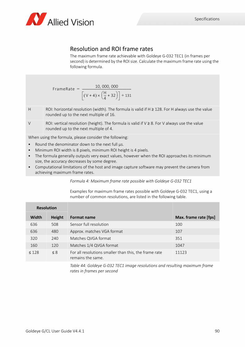
Specifications
Resolution and ROI frame ratesThe maximum frame rate achievable with Goldeye G-032 TEC1 (in frames per second) is determined by the ROI size. Calculate the maximum frame rate using the following formula.
Examples for maximum frame rates possible with Goldeye G-032 TEC1, using a number of common resolutions, are listed in the following table.
H ROI: horizontal resolution (width). The formula is valid if H ≥ 128. For H always use the value rounded up to the next multiple of 16.
V ROI: vertical resolution (height). The formula is valid if V ≥ 8. For V always use the value rounded up to the next multiple of 4.
When using the formula, please consider the following:
• Round the denominator down to the next full µs.
• Minimum ROI width is 8 pixels, minimum ROI height is 4 pixels.
• The formula generally outputs very exact values, however when the ROI approaches its minimum size, the accuracy decreases by some degree.
• Computational limitations of the host and image capture software may prevent the camera from achieving maximum frame rates.
Formula 4: Maximum frame rate possible with Goldeye G-032 TEC1
Resolution
Format name Max. frame rate [fps]Width Height
636 508 Sensor full resolution 100
636 480 Approx. matches VGA format 107
320 240 Matches QVGA format 351
160 120 Matches 1/4 QVGA format 1047
≤ 128 ≤ 8 For all resolutions smaller than this, the frame rate remains the same.
11123
Table 44: Goldeye G-032 TEC1 image resolutions and resulting maximum frame rates in frames per second
FrameRate10 000 000, ,
V 4+ H4---- 32+ 131+
-----------------------------------------------------------------------=
90Goldeye G/CL User Guide V4.4.1

Specifications
Goldeye G-032 Cool TEC2
Imaging and performance
Parameter Values
Sensor InGaAs, progressive scan, electronic full frame shutter
Sensor type FPA
Spectral range 900 nm to 1700 nm
Resolution (H) × (V) 636 × 508
Pixel size 25 μm × 25 μm
Effective chip size 15.9 mm × 12.7 mm
Dark current (at -20 °C FPA temperature)
30 ke¯/s
Temporal dark noise (Gain0) 400 e¯
Temporal dark noise (Gain1) 170 e¯
Saturation capacity (Gain0) 1.9 Me¯
Saturation capacity (Gain1) 39 ke¯
Dynamic range (Gain0) 73 dB
Dynamic range (Gain1) 47 dB
Pixel operability >99.5%
Exposure time 6 µs to 1250 ms 1
Max. frame rate at full resolution
100 fps
Temperature control Dual-stage thermo-electric cooling (TEC2)
Analog gain factor 1 (Gain0), 50 (Gain1)
A/D converter 14-bit
Image buffer size 256 MB
Stream hold capacity 397 frames at full resolution
1 Maximum exposure value given is valid for Gain0 and sensor temperature of -20°C. Even longer exposures can be set, but the image quality may deteriorate.
Table 45: Goldeye G-032 Cool TEC2 imaging and performance
91Goldeye G/CL User Guide V4.4.1
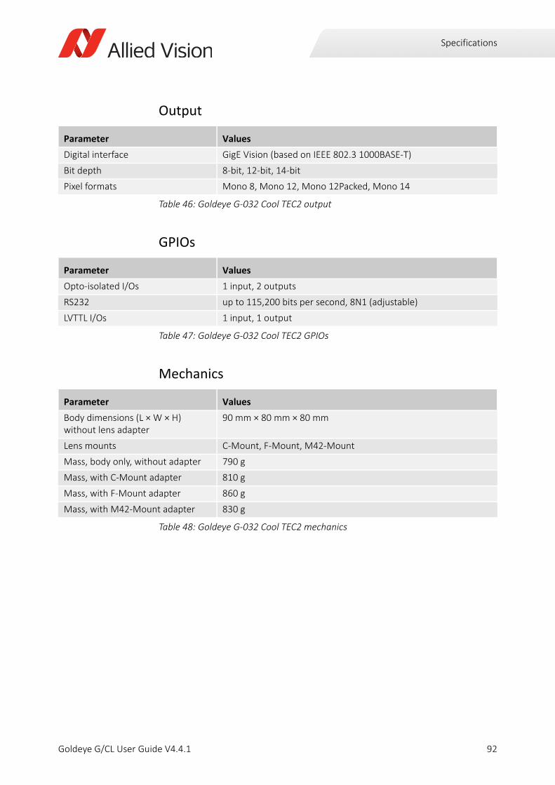
Specifications
Output
GPIOs
Mechanics
Parameter Values
Digital interface GigE Vision (based on IEEE 802.3 1000BASE-T)
Bit depth 8-bit, 12-bit, 14-bit
Pixel formats Mono 8, Mono 12, Mono 12Packed, Mono 14
Table 46: Goldeye G-032 Cool TEC2 output
Parameter Values
Opto-isolated I/Os 1 input, 2 outputs
RS232 up to 115,200 bits per second, 8N1 (adjustable)
LVTTL I/Os 1 input, 1 output
Table 47: Goldeye G-032 Cool TEC2 GPIOs
Parameter Values
Body dimensions (L × W × H)without lens adapter
90 mm × 80 mm × 80 mm
Lens mounts C-Mount, F-Mount, M42-Mount
Mass, body only, without adapter 790 g
Mass, with C-Mount adapter 810 g
Mass, with F-Mount adapter 860 g
Mass, with M42-Mount adapter 830 g
Table 48: Goldeye G-032 Cool TEC2 mechanics
92Goldeye G/CL User Guide V4.4.1
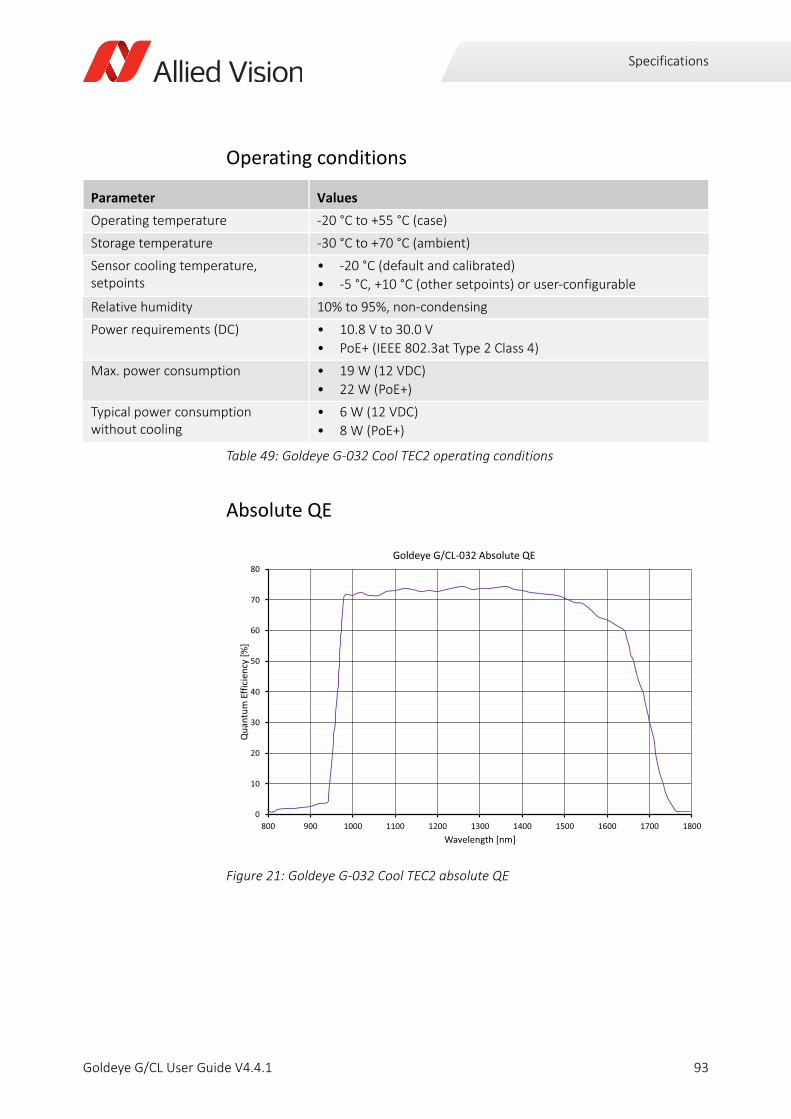
Specifications
Operating conditions
Absolute QE
Parameter Values
Operating temperature -20 °C to +55 °C (case)
Storage temperature -30 °C to +70 °C (ambient)
Sensor cooling temperature, setpoints
• -20 °C (default and calibrated)
• -5 °C, +10 °C (other setpoints) or user-configurable
Relative humidity 10% to 95%, non-condensing
Power requirements (DC) • 10.8 V to 30.0 V
• PoE+ (IEEE 802.3at Type 2 Class 4)
Max. power consumption • 19 W (12 VDC)
• 22 W (PoE+)
Typical power consumption without cooling
• 6 W (12 VDC)
• 8 W (PoE+)
Table 49: Goldeye G-032 Cool TEC2 operating conditions
Figure 21: Goldeye G-032 Cool TEC2 absolute QE
0
10
20
30
40
50
60
70
80
800 900 1000 1100 1200 1300 1400 1500 1600 1700 1800
Qua
ntum
Effic
ienc
y[%
]
Wavelength [nm]
Goldeye G/CL 032 Absolute QE
93Goldeye G/CL User Guide V4.4.1
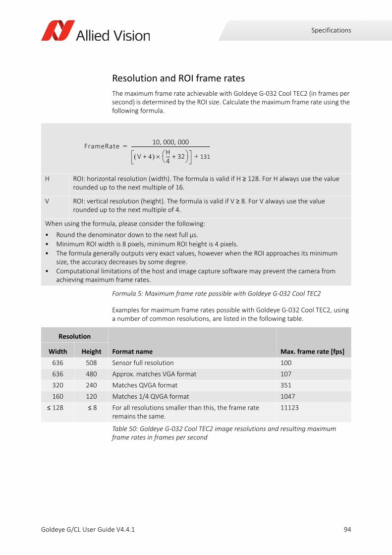
Specifications
Resolution and ROI frame rates
The maximum frame rate achievable with Goldeye G-032 Cool TEC2 (in frames per second) is determined by the ROI size. Calculate the maximum frame rate using the following formula.
Examples for maximum frame rates possible with Goldeye G-032 Cool TEC2, using a number of common resolutions, are listed in the following table.
H ROI: horizontal resolution (width). The formula is valid if H ≥ 128. For H always use the value rounded up to the next multiple of 16.
V ROI: vertical resolution (height). The formula is valid if V ≥ 8. For V always use the value rounded up to the next multiple of 4.
When using the formula, please consider the following:
• Round the denominator down to the next full µs.
• Minimum ROI width is 8 pixels, minimum ROI height is 4 pixels.
• The formula generally outputs very exact values, however when the ROI approaches its minimum size, the accuracy decreases by some degree.
• Computational limitations of the host and image capture software may prevent the camera from achieving maximum frame rates.
Formula 5: Maximum frame rate possible with Goldeye G-032 Cool TEC2
Resolution
Format name Max. frame rate [fps]Width Height
636 508 Sensor full resolution 100
636 480 Approx. matches VGA format 107
320 240 Matches QVGA format 351
160 120 Matches 1/4 QVGA format 1047
≤ 128 ≤ 8 For all resolutions smaller than this, the frame rate remains the same.
11123
Table 50: Goldeye G-032 Cool TEC2 image resolutions and resulting maximum frame rates in frames per second
FrameRate10 000 000, ,
V 4+ H4---- 32+ 131+
-----------------------------------------------------------------------=
94Goldeye G/CL User Guide V4.4.1
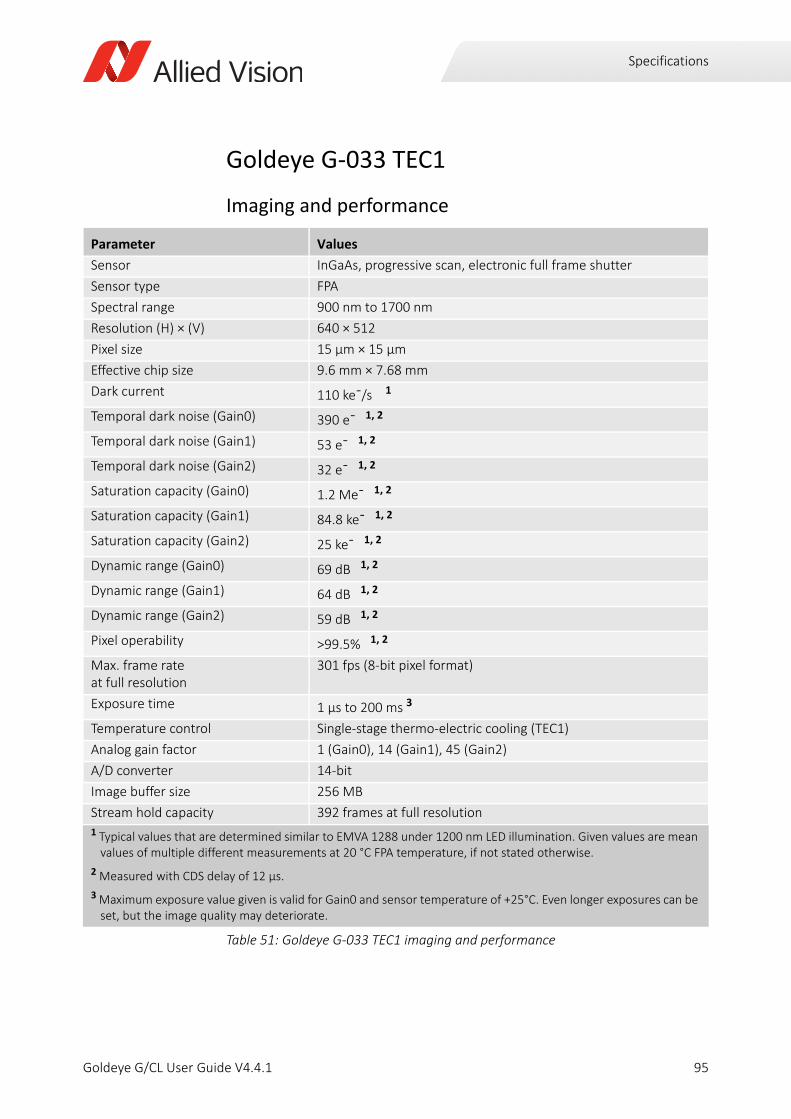
Specifications
Goldeye G-033 TEC1
Imaging and performance
Parameter Values
Sensor InGaAs, progressive scan, electronic full frame shutter
Sensor type FPA
Spectral range 900 nm to 1700 nm
Resolution (H) × (V) 640 × 512
Pixel size 15 μm × 15 μm
Effective chip size 9.6 mm × 7.68 mm
Dark current 110 ke¯/s 1
Temporal dark noise (Gain0) 390 e¯ 1, 2
Temporal dark noise (Gain1) 53 e¯ 1, 2
Temporal dark noise (Gain2) 32 e¯ 1, 2
Saturation capacity (Gain0) 1.2 Me¯ 1, 2
Saturation capacity (Gain1) 84.8 ke¯ 1, 2
Saturation capacity (Gain2) 25 ke¯ 1, 2
Dynamic range (Gain0) 69 dB 1, 2
Dynamic range (Gain1) 64 dB 1, 2
Dynamic range (Gain2) 59 dB 1, 2
Pixel operability >99.5% 1, 2
Max. frame rate at full resolution
301 fps (8-bit pixel format)
Exposure time 1 µs to 200 ms 3
Temperature control Single-stage thermo-electric cooling (TEC1)
Analog gain factor 1 (Gain0), 14 (Gain1), 45 (Gain2)
A/D converter 14-bit
Image buffer size 256 MB
Stream hold capacity 392 frames at full resolution
1 Typical values that are determined similar to EMVA 1288 under 1200 nm LED illumination. Given values are mean values of multiple different measurements at 20 °C FPA temperature, if not stated otherwise.
2 Measured with CDS delay of 12 µs.
3 Maximum exposure value given is valid for Gain0 and sensor temperature of +25°C. Even longer exposures can be set, but the image quality may deteriorate.
Table 51: Goldeye G-033 TEC1 imaging and performance
95Goldeye G/CL User Guide V4.4.1

Specifications
Output
GPIOs
Mechanics
Parameter Values
Digital interface GigE Vision (based on IEEE 802.3 1000BASE-T)
Bit depth 8-bit, 12-bit, 14-bit
Pixel formats Mono 8, Mono 12, Mono 12Packed, Mono 14
Table 52: Goldeye G-033 TEC1 output
Parameter Values
Opto-isolated I/Os 1 input, 2 outputs
RS232 up to 115,200 bits per second, 8N1 (adjustable)
LVTTL I/Os 1 input, 1 output
Table 53: Goldeye G-033 TEC1 GPIOs
Parameter Values
Body dimensions (L × W × H)without lens adapter
78 mm × 55 mm × 55 mm
Lens mounts C-Mount, F-Mount, M42-Mount
Mass, body only, without adapter 350 g
Mass, with C-Mount adapter 370 g
Mass, with F-Mount adapter 430 g
Mass, with M42-Mount adapter 390 g
Table 54: Goldeye G-033 TEC1 mechanics
96Goldeye G/CL User Guide V4.4.1

Specifications
Operating conditions
Absolute QE
Parameter Values
Operating temperature -20 °C to +55 °C (case)
Storage temperature -30 °C to +70 °C (ambient)
Sensor cooling temperature, setpoints
• +20 °C (default and calibrated)
• +5 °C, +35 °C, +50 °C (other setpoints) or user-configurable
Relative humidity 10% to 95%, non-condensing
Power requirements (DC) • 10.8 V to 30.0 V
• PoE (IEEE 802.3at Type 1 Class 0)
Max. power consumption • 10.8 W (12 VDC)
• <12.95 W (PoE)
Typical power consumption without cooling
• 6.3W (12 VDC)
• 8 W (PoE)
Table 55: Goldeye G-033 TEC1 operating conditions
Figure 22: Goldeye G-033 TEC1 absolute QE
0
10
20
30
40
50
60
70
80
90
800 900 1000 1100 1200 1300 1400 1500 1600 1700 1800
Qua
ntum
Effic
ienc
y[%
]
Wavelength [nm]
Goldeye G/CL 033 Absolute QE
97Goldeye G/CL User Guide V4.4.1
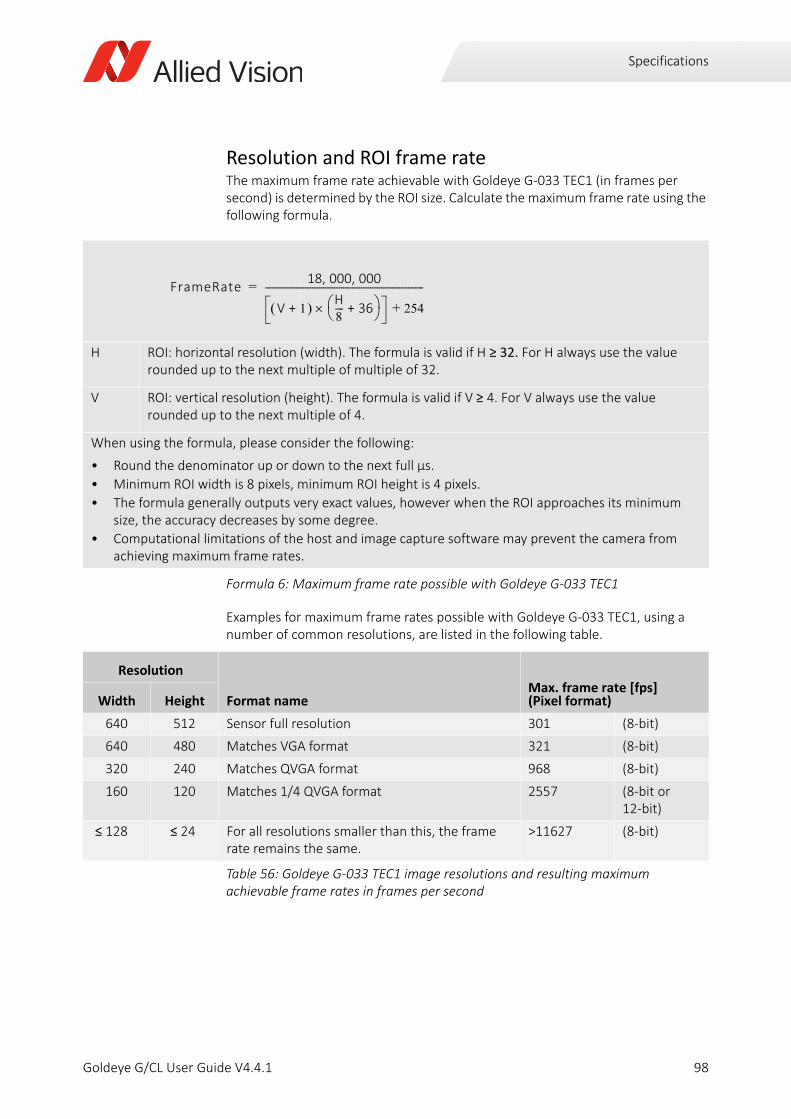
Specifications
Resolution and ROI frame rateThe maximum frame rate achievable with Goldeye G-033 TEC1 (in frames per second) is determined by the ROI size. Calculate the maximum frame rate using the following formula.
Examples for maximum frame rates possible with Goldeye G-033 TEC1, using a number of common resolutions, are listed in the following table.
H ROI: horizontal resolution (width). The formula is valid if H ≥ 32. For H always use the value rounded up to the next multiple of multiple of 32.
V ROI: vertical resolution (height). The formula is valid if V ≥ 4. For V always use the value rounded up to the next multiple of 4.
When using the formula, please consider the following:
• Round the denominator up or down to the next full µs.
• Minimum ROI width is 8 pixels, minimum ROI height is 4 pixels.
• The formula generally outputs very exact values, however when the ROI approaches its minimum size, the accuracy decreases by some degree.
• Computational limitations of the host and image capture software may prevent the camera from achieving maximum frame rates.
Formula 6: Maximum frame rate possible with Goldeye G-033 TEC1
Resolution
Format nameMax. frame rate [fps](Pixel format)Width Height
640 512 Sensor full resolution 301 (8-bit)
640 480 Matches VGA format 321 (8-bit)
320 240 Matches QVGA format 968 (8-bit)
160 120 Matches 1/4 QVGA format 2557 (8-bit or 12-bit)
≤ 128 ≤ 24 For all resolutions smaller than this, the frame rate remains the same.
>11627 (8-bit)
Table 56: Goldeye G-033 TEC1 image resolutions and resulting maximum achievable frame rates in frames per second
FrameRate18 000 000, ,
V 1+ H8---- 36+ 254+
-----------------------------------------------------------------------=
98Goldeye G/CL User Guide V4.4.1
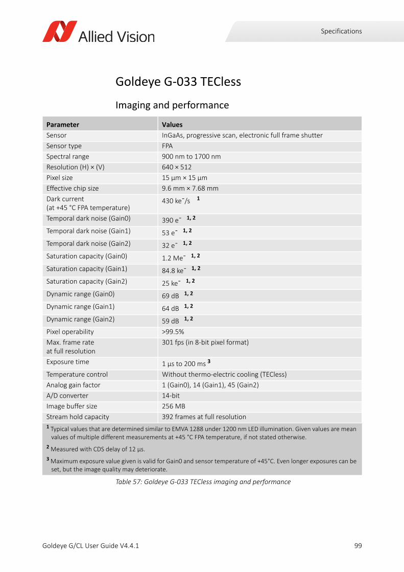
Specifications
Goldeye G-033 TECless
Imaging and performance
Parameter Values
Sensor InGaAs, progressive scan, electronic full frame shutter
Sensor type FPA
Spectral range 900 nm to 1700 nm
Resolution (H) × (V) 640 × 512
Pixel size 15 μm × 15 μm
Effective chip size 9.6 mm × 7.68 mm
Dark current (at +45 °C FPA temperature)
430 ke¯/s 1
Temporal dark noise (Gain0) 390 e¯ 1, 2
Temporal dark noise (Gain1) 53 e¯ 1, 2
Temporal dark noise (Gain2) 32 e¯ 1, 2
Saturation capacity (Gain0) 1.2 Me¯ 1, 2
Saturation capacity (Gain1) 84.8 ke¯ 1, 2
Saturation capacity (Gain2) 25 ke¯ 1, 2
Dynamic range (Gain0) 69 dB 1, 2
Dynamic range (Gain1) 64 dB 1, 2
Dynamic range (Gain2) 59 dB 1, 2
Pixel operability >99.5%
Max. frame rate at full resolution
301 fps (in 8-bit pixel format)
Exposure time 1 µs to 200 ms 3
Temperature control Without thermo-electric cooling (TECless)
Analog gain factor 1 (Gain0), 14 (Gain1), 45 (Gain2)
A/D converter 14-bit
Image buffer size 256 MB
Stream hold capacity 392 frames at full resolution1 Typical values that are determined similar to EMVA 1288 under 1200 nm LED illumination. Given values are mean
values of multiple different measurements at +45 °C FPA temperature, if not stated otherwise.
2 Measured with CDS delay of 12 µs.
3 Maximum exposure value given is valid for Gain0 and sensor temperature of +45°C. Even longer exposures can be set, but the image quality may deteriorate.
Table 57: Goldeye G-033 TECless imaging and performance
99Goldeye G/CL User Guide V4.4.1

Specifications
Output
GPIOs
Mechanics
Parameter Values
Digital interface GigE Vision (based on IEEE 802.3 1000BASE-T)
Bit depth 8-bit, 12-bit, 14-bit
Pixel formats Mono 8, Mono 12, Mono 12Packed, Mono 14
Table 58: Goldeye G-033 TECless output
Parameter Values
Opto-isolated I/Os 1 input, 2 outputs
RS232 up to 115,200 bits per second, 8N1 (adjustable)
LVTTL I/Os 1 input, 1 output
Table 59: Goldeye G-033 TECless GPIOs
Parameter Values
Body dimensions (L × W × H)without lens adapter
78 mm × 55 mm × 55 mm
Lens mounts • C-Mount
• F-Mount and M42-Mount available on request
Mass, body only, without adapter 330 g
Mass, with C-Mount adapter 350 g
Mass, with F-Mount adapter 400 g
Mass, with M42-Mount adapter 370 g
Table 60: Goldeye G-033 TECless mechanics
100Goldeye G/CL User Guide V4.4.1

Specifications
Operating conditions
Absolute QE
Parameter Values
Operating temperature -20 °C to +55 °C (case)
Storage temperature -30 °C to +70 °C (ambient)
Sensor cooling temperature, setpoints
(Not applicable to TECless models.)
Relative humidity 10% to 95%, non-condensing
Power requirements (DC) • 10.8 V to 30.0 V
• PoE (IEEE 802.3at Type 1 Class 0)
Max. power consumption • 6.0 W (12 VDC)
• <7.5 W (PoE)
Typical power consumption without cooling
• 6.0 W (12 VDC)
• 6.0 W (PoE)
Table 61: Goldeye G-033 TECless operating conditions
Figure 23: Goldeye G-033 TECless absolute QE
0
10
20
30
40
50
60
70
80
90
800 900 1000 1100 1200 1300 1400 1500 1600 1700 1800
Qua
ntum
Effic
ienc
y[%
]
Wavelength [nm]
Goldeye G/CL 033 Absolute QE
101Goldeye G/CL User Guide V4.4.1
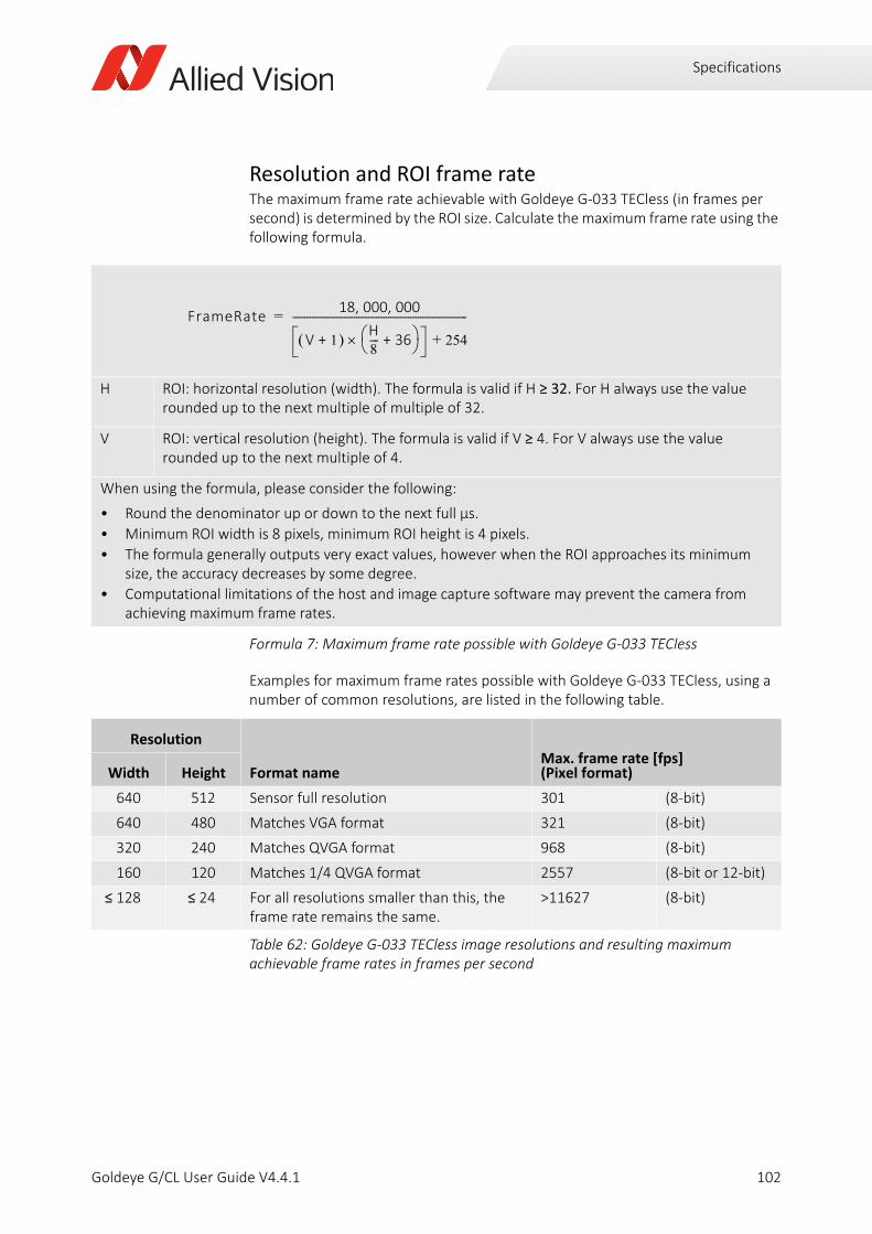
Specifications
Resolution and ROI frame rateThe maximum frame rate achievable with Goldeye G-033 TECless (in frames per second) is determined by the ROI size. Calculate the maximum frame rate using the following formula.
Examples for maximum frame rates possible with Goldeye G-033 TECless, using a number of common resolutions, are listed in the following table.
H ROI: horizontal resolution (width). The formula is valid if H ≥ 32. For H always use the value rounded up to the next multiple of multiple of 32.
V ROI: vertical resolution (height). The formula is valid if V ≥ 4. For V always use the value rounded up to the next multiple of 4.
When using the formula, please consider the following:
• Round the denominator up or down to the next full µs.
• Minimum ROI width is 8 pixels, minimum ROI height is 4 pixels.
• The formula generally outputs very exact values, however when the ROI approaches its minimum size, the accuracy decreases by some degree.
• Computational limitations of the host and image capture software may prevent the camera from achieving maximum frame rates.
Formula 7: Maximum frame rate possible with Goldeye G-033 TECless
Resolution
Format nameMax. frame rate [fps](Pixel format)Width Height
640 512 Sensor full resolution 301 (8-bit)
640 480 Matches VGA format 321 (8-bit)
320 240 Matches QVGA format 968 (8-bit)
160 120 Matches 1/4 QVGA format 2557 (8-bit or 12-bit)
≤ 128 ≤ 24 For all resolutions smaller than this, the frame rate remains the same.
>11627 (8-bit)
Table 62: Goldeye G-033 TECless image resolutions and resulting maximum achievable frame rates in frames per second
FrameRate18 000 000, ,
V 1+ H8---- 36+ 254+
-----------------------------------------------------------------------=
102Goldeye G/CL User Guide V4.4.1
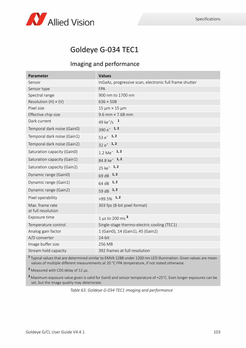
Specifications
Goldeye G-034 TEC1
Imaging and performance
Parameter Values
Sensor InGaAs, progressive scan, electronic full frame shutter
Sensor type FPA
Spectral range 900 nm to 1700 nm
Resolution (H) × (V) 636 × 508
Pixel size 15 μm × 15 μm
Effective chip size 9.6 mm × 7.68 mm
Dark current 49 ke¯/s 1
Temporal dark noise (Gain0) 390 e¯ 1, 2
Temporal dark noise (Gain1) 53 e¯ 1, 2
Temporal dark noise (Gain2) 32 e¯ 1, 2
Saturation capacity (Gain0) 1.2 Me¯ 1, 2
Saturation capacity (Gain1) 84.8 ke¯ 1, 2
Saturation capacity (Gain2) 25 ke¯ 1, 2
Dynamic range (Gain0) 69 dB 1, 2
Dynamic range (Gain1) 64 dB 1, 2
Dynamic range (Gain2) 59 dB 1, 2
Pixel operability >99.5% 1, 2
Max. frame rate at full resolution
303 fps (8-bit pixel format)
Exposure time 1 µs to 200 ms 3
Temperature control Single-stage thermo-electric cooling (TEC1)
Analog gain factor 1 (Gain0), 14 (Gain1), 45 (Gain2)
A/D converter 14-bit
Image buffer size 256 MB
Stream hold capacity 392 frames at full resolution1 Typical values that are determined similar to EMVA 1288 under 1200 nm LED illumination. Given values are mean
values of multiple different measurements at 20 °C FPA temperature, if not stated otherwise.
2 Measured with CDS delay of 12 µs.
3 Maximum exposure value given is valid for Gain0 and sensor temperature of +25°C. Even longer exposures can be set, but the image quality may deteriorate.
Table 63: Goldeye G-034 TEC1 imaging and performance
103Goldeye G/CL User Guide V4.4.1

Specifications
Output
GPIOs
Mechanics
Parameter Values
Digital interface GigE Vision (based on IEEE 802.3 1000BASE-T)
Bit depth 8-bit, 12-bit, 14-bit
Pixel formats Mono 8, Mono 12, Mono 12Packed, Mono 14
Table 64: Goldeye G-034 TEC1 output
Parameter Values
Opto-isolated I/Os 1 input, 2 outputs
RS232 up to 115,200 bits per second, 8N1 (adjustable)
LVTTL I/Os 1 input, 1 output
Table 65: Goldeye G-034 TEC1 GPIOs
Parameter Values
Body dimensions (L × W × H)without lens adapter
78 mm × 55 mm × 55 mm
Lens mounts C-Mount, F-Mount, M42-Mount
Mass, body only, without adapter 350 g
Mass, with C-Mount adapter 370 g
Mass, with F-Mount adapter 430 g
Mass, with M42-Mount adapter 390 g
Table 66: Goldeye G-034 TEC1 mechanics
104Goldeye G/CL User Guide V4.4.1

Specifications
Operating conditions
Absolute QE
Parameter Values
Operating temperature -20 °C to +55 °C (case)
Storage temperature -30 °C to +70 °C (ambient)
Sensor cooling temperature, setpoints
• +20 °C (default and calibrated)
• +5 °C, +35 °C, +50 °C (other setpoints) or user-configurable
Relative humidity 10% to 95%, non-condensing
Power requirements (DC) • 10.8 V to 30.0 V
• PoE (IEEE 802.3at Type 1 Class 0)
Max. power consumption • 10.8 W (12 VDC)
• <12.95 W (PoE)
Typical power consumption without cooling
• 6.3 W (12 VDC)
• 8 W (PoE)
Table 67: Goldeye G-034 TEC1 operating conditions
Figure 24: Goldeye G-034 TEC1 absolute QE
0
10
20
30
40
50
60
70
80
90
800 900 1000 1100 1200 1300 1400 1500 1600 1700 1800
Qua
ntum
Effic
ienc
y[%
]
Wavelength [nm]
Goldeye G/CL 034 Absolute QE
105Goldeye G/CL User Guide V4.4.1
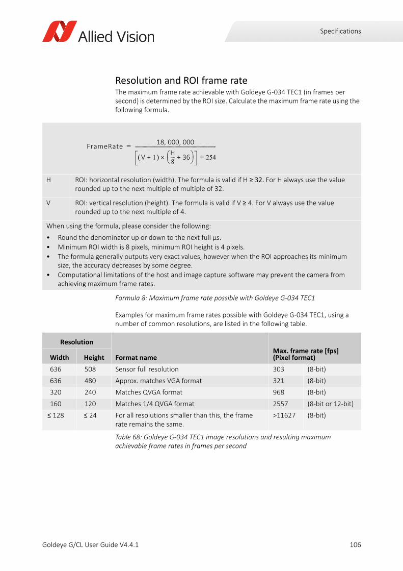
Specifications
Resolution and ROI frame rateThe maximum frame rate achievable with Goldeye G-034 TEC1 (in frames per second) is determined by the ROI size. Calculate the maximum frame rate using the following formula.
Examples for maximum frame rates possible with Goldeye G-034 TEC1, using a number of common resolutions, are listed in the following table.
H ROI: horizontal resolution (width). The formula is valid if H ≥ 32. For H always use the value rounded up to the next multiple of multiple of 32.
V ROI: vertical resolution (height). The formula is valid if V ≥ 4. For V always use the value rounded up to the next multiple of 4.
When using the formula, please consider the following:
• Round the denominator up or down to the next full µs.
• Minimum ROI width is 8 pixels, minimum ROI height is 4 pixels.
• The formula generally outputs very exact values, however when the ROI approaches its minimum size, the accuracy decreases by some degree.
• Computational limitations of the host and image capture software may prevent the camera from achieving maximum frame rates.
Formula 8: Maximum frame rate possible with Goldeye G-034 TEC1
Resolution
Format nameMax. frame rate [fps](Pixel format)Width Height
636 508 Sensor full resolution 303 (8-bit)
636 480 Approx. matches VGA format 321 (8-bit)
320 240 Matches QVGA format 968 (8-bit)
160 120 Matches 1/4 QVGA format 2557 (8-bit or 12-bit)
≤ 128 ≤ 24 For all resolutions smaller than this, the frame rate remains the same.
>11627 (8-bit)
Table 68: Goldeye G-034 TEC1 image resolutions and resulting maximum achievable frame rates in frames per second
FrameRate18 000 000, ,
V 1+ H8---- 36+ 254+
-----------------------------------------------------------------------=
106Goldeye G/CL User Guide V4.4.1

Specifications
Goldeye G-130 TEC1
Imaging and performance
Parameter Values
Sensor model Sony IMX990 SenSWIR
Sensor type InGaAs
Sensor format Type 1/2 (8.2 mm diagonal)
Shutter type Global shutter
Spectral range 400 nm to 1700 nm
Resolution 1280 (H) × 1024 (V)
Pixel size 5 μm × 5 μm
Effective chip size 6.4 mm × 5.12 mm
Dark current (at +20 °C FPA temperature)
4.8 ke¯/s
Temporal dark noise (0 dB) 250 e¯
Temporal dark noise (18 dB) 210 e¯
Saturation capacity (0 dB) 165 ke¯
Saturation capacity (18 dB) 17.2 ke¯
Dynamic range (0 dB) 56.4 dB
Dynamic range (18 dB) 38.2 dB
Pixel operability >99.5%
Exposure time 18 µs to 200 ms 1
Max. frame rate at full resolution 94 fps
Temperature control Single-stage thermo-electric cooling (TEC1)
Analog gain factor 1 (0 dB), 7.9 (18 dB)
A/D converter 12-bit
Image buffer size 256 MB
Stream hold capacity 95 frames at full resolution
1 Maximum exposure value given is valid for 0 dB and sensor temperature of +20°C. Even longer exposures can be set, but the image quality may deteriorate.
Table 69: Goldeye G-130 TEC1 imaging and performance
107Goldeye G/CL User Guide V4.4.1

Specifications
Output
GPIOs
Mechanics
Parameter Values
Digital interface GigE Vision (based on IEEE 802.3 1000BASE-T)
Bit depth 8-bit, 12-bit
Pixel formats Mono 8, Mono 12, Mono 12Packed
Table 70: Goldeye G-130 TEC1 output
Parameter Values
Opto-isolated I/Os 1 input, 2 outputs
RS232 up to 115,200 bits per second, 8N1 (adjustable)
LVTTL I/Os 1 input, 1 output
Table 71: Goldeye G-130 TEC1 GPIOs
Parameter Values
Body dimensions (L × W × H)including lens mount
78 × 55 × 55 mm
Lens mount C-Mount
Mass, including lens mount 340 g
Table 72: Goldeye G-130 TEC1 mechanics
108Goldeye G/CL User Guide V4.4.1

Specifications
Operating conditions
Relative QE
Parameter Values
Operating temperature -20 °C to +55 °C (case)
Storage temperature -30 °C to +70 °C (ambient)
Sensor cooling temperature, setpoints
• +20 °C (default and calibrated)
• +5 °C, +35 °C, +50 °C (other setpoints) or user-configurable
Relative humidity 10% to 95%, non-condensing
Power requirements (DC) • 10.8 V to 30.0 V
• PoE (IEEE 802.3at Type 1 Class 0)
Max. power consumption • 10.8 W (12 VDC)
• <12.95 W (PoE)
Typical power consumption without cooling
• 6.1 W (12 VDC)
• 7.4 W (PoE)
Table 73: Goldeye G-130 TEC1 operating conditions
Figure 25: Goldeye G-130 TEC1 relative QE
0%
10%
20%
30%
40%
50%
60%
70%
80%
400 500 600 700 800 900 1000 1100 1200 1300 1400 1500 1600 1700 1800
Qua
ntum
Eci
ency
[%]
Wavelength [nm]
Sony IMX990, IMX991 QE
109Goldeye G/CL User Guide V4.4.1
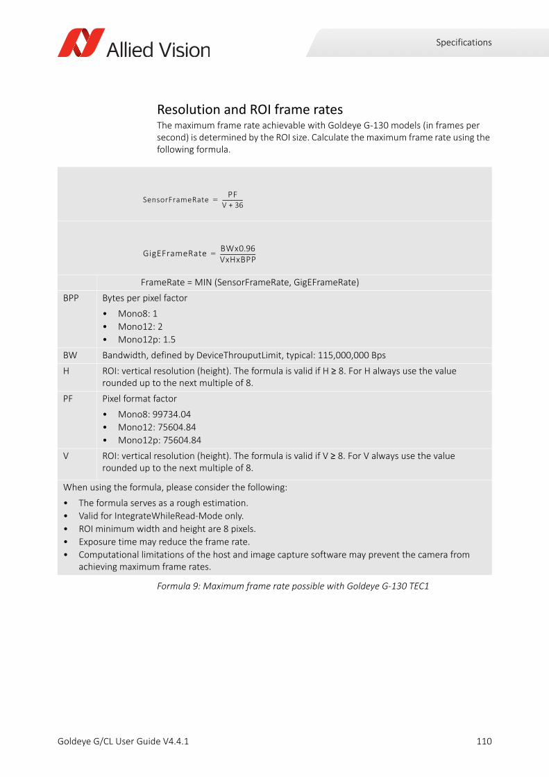
Specifications
Resolution and ROI frame ratesThe maximum frame rate achievable with Goldeye G-130 models (in frames per second) is determined by the ROI size. Calculate the maximum frame rate using the following formula.
FrameRate = MIN (SensorFrameRate, GigEFrameRate)
BPP Bytes per pixel factor
• Mono8: 1
• Mono12: 2
• Mono12p: 1.5
BW Bandwidth, defined by DeviceThrouputLimit, typical: 115,000,000 Bps
H ROI: vertical resolution (height). The formula is valid if H ≥ 8. For H always use the value rounded up to the next multiple of 8.
PF Pixel format factor
• Mono8: 99734.04
• Mono12: 75604.84
• Mono12p: 75604.84
V ROI: vertical resolution (height). The formula is valid if V ≥ 8. For V always use the value rounded up to the next multiple of 8.
When using the formula, please consider the following:
• The formula serves as a rough estimation.
• Valid for IntegrateWhileRead-Mode only.
• ROI minimum width and height are 8 pixels.
• Exposure time may reduce the frame rate.
• Computational limitations of the host and image capture software may prevent the camera from achieving maximum frame rates.
Formula 9: Maximum frame rate possible with Goldeye G-130 TEC1
SensorFrameRatePF
V 36+----------------=
GigEFrameRateBWx0.96VxHxBPP----------------------------=
110Goldeye G/CL User Guide V4.4.1
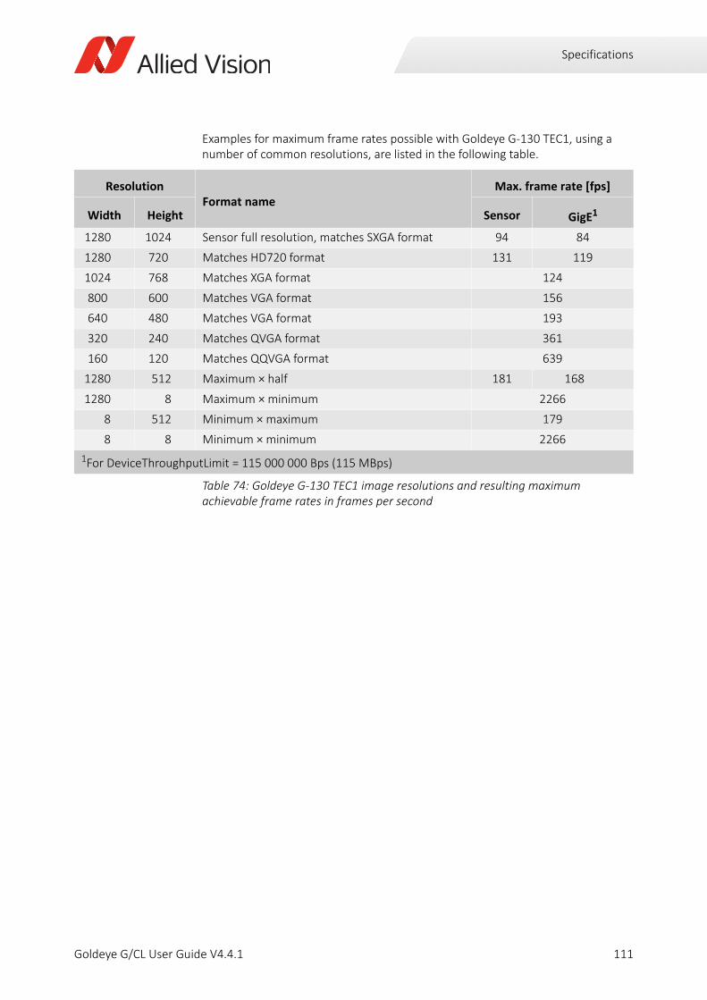
Specifications
Examples for maximum frame rates possible with Goldeye G-130 TEC1, using a number of common resolutions, are listed in the following table.
ResolutionFormat name
Max. frame rate [fps]
Width Height Sensor GigE1
1280 1024 Sensor full resolution, matches SXGA format 94 84
1280 720 Matches HD720 format 131 119
1024 768 Matches XGA format 124
800 600 Matches VGA format 156
640 480 Matches VGA format 193
320 240 Matches QVGA format 361
160 120 Matches QQVGA format 639
1280 512 Maximum × half 181 168
1280 8 Maximum × minimum 2266
8 512 Minimum × maximum 179
8 8 Minimum × minimum 2266
1For DeviceThroughputLimit = 115 000 000 Bps (115 MBps)
Table 74: Goldeye G-130 TEC1 image resolutions and resulting maximum achievable frame rates in frames per second
111Goldeye G/CL User Guide V4.4.1
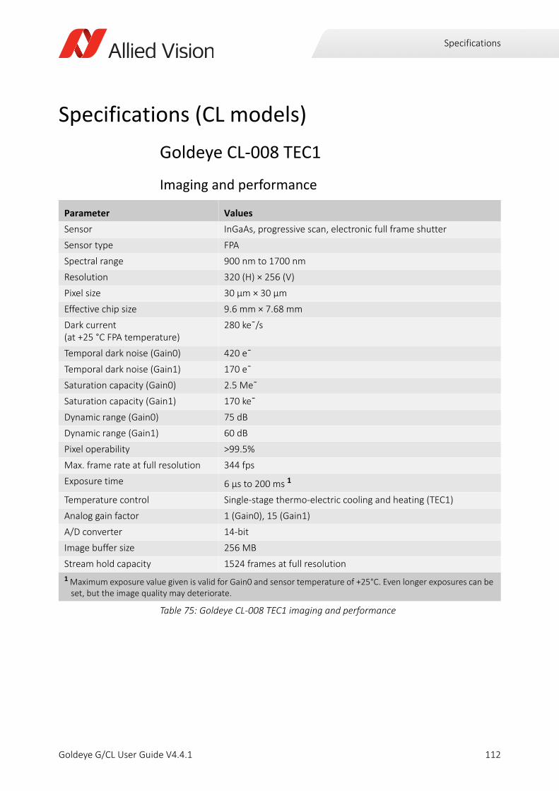
Specifications
Specifications (CL models)
Goldeye CL-008 TEC1
Imaging and performance
Parameter Values
Sensor InGaAs, progressive scan, electronic full frame shutter
Sensor type FPA
Spectral range 900 nm to 1700 nm
Resolution 320 (H) × 256 (V)
Pixel size 30 μm × 30 μm
Effective chip size 9.6 mm × 7.68 mm
Dark current (at +25 °C FPA temperature)
280 ke¯/s
Temporal dark noise (Gain0) 420 e¯
Temporal dark noise (Gain1) 170 e¯
Saturation capacity (Gain0) 2.5 Me¯
Saturation capacity (Gain1) 170 ke¯
Dynamic range (Gain0) 75 dB
Dynamic range (Gain1) 60 dB
Pixel operability >99.5%
Max. frame rate at full resolution 344 fps
Exposure time 6 µs to 200 ms 1
Temperature control Single-stage thermo-electric cooling and heating (TEC1)
Analog gain factor 1 (Gain0), 15 (Gain1)
A/D converter 14-bit
Image buffer size 256 MB
Stream hold capacity 1524 frames at full resolution
1 Maximum exposure value given is valid for Gain0 and sensor temperature of +25°C. Even longer exposures can be set, but the image quality may deteriorate.
Table 75: Goldeye CL-008 TEC1 imaging and performance
112Goldeye G/CL User Guide V4.4.1
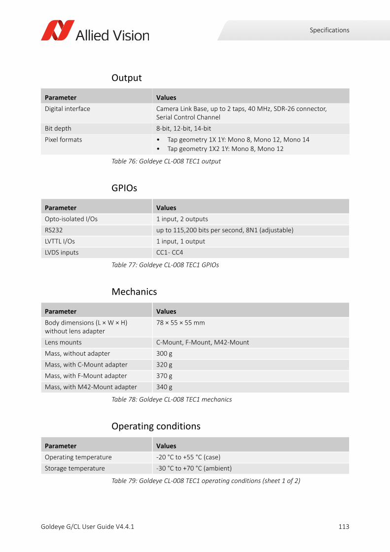
Specifications
Output
GPIOs
Mechanics
Operating conditions
Parameter Values
Digital interface Camera Link Base, up to 2 taps, 40 MHz, SDR-26 connector, Serial Control Channel
Bit depth 8-bit, 12-bit, 14-bit
Pixel formats • Tap geometry 1X 1Y: Mono 8, Mono 12, Mono 14
• Tap geometry 1X2 1Y: Mono 8, Mono 12
Table 76: Goldeye CL-008 TEC1 output
Parameter Values
Opto-isolated I/Os 1 input, 2 outputs
RS232 up to 115,200 bits per second, 8N1 (adjustable)
LVTTL I/Os 1 input, 1 output
LVDS inputs CC1 - CC4
Table 77: Goldeye CL-008 TEC1 GPIOs
Parameter Values
Body dimensions (L × W × H) without lens adapter
78 × 55 × 55 mm
Lens mounts C-Mount, F-Mount, M42-Mount
Mass, without adapter 300 g
Mass, with C-Mount adapter 320 g
Mass, with F-Mount adapter 370 g
Mass, with M42-Mount adapter 340 g
Table 78: Goldeye CL-008 TEC1 mechanics
Parameter Values
Operating temperature -20 °C to +55 °C (case)
Storage temperature -30 °C to +70 °C (ambient)
Table 79: Goldeye CL-008 TEC1 operating conditions (sheet 1 of 2)
113Goldeye G/CL User Guide V4.4.1
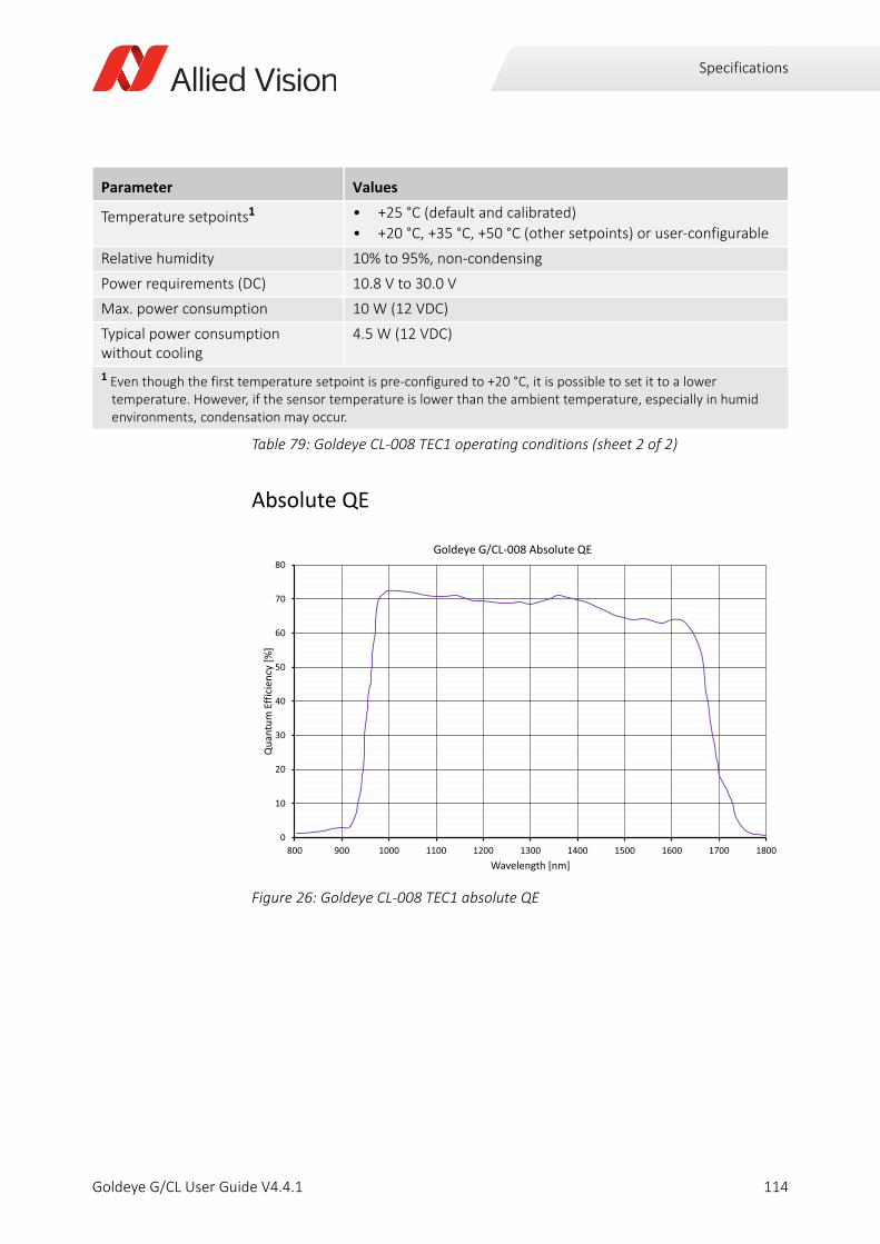
Specifications
Absolute QE
Temperature setpoints1 • +25 °C (default and calibrated)
• +20 °C, +35 °C, +50 °C (other setpoints) or user-configurable
Relative humidity 10% to 95%, non-condensing
Power requirements (DC) 10.8 V to 30.0 V
Max. power consumption 10 W (12 VDC)
Typical power consumption without cooling
4.5 W (12 VDC)
1 Even though the first temperature setpoint is pre-configured to +20 °C, it is possible to set it to a lower temperature. However, if the sensor temperature is lower than the ambient temperature, especially in humid environments, condensation may occur.
Figure 26: Goldeye CL-008 TEC1 absolute QE
Parameter Values
Table 79: Goldeye CL-008 TEC1 operating conditions (sheet 2 of 2)
0
10
20
30
40
50
60
70
80
800 900 1000 1100 1200 1300 1400 1500 1600 1700 1800
Qua
ntum
Effic
ienc
y[%
]
Wavelength [nm]
Goldeye G/CL 008 Absolute QE
114Goldeye G/CL User Guide V4.4.1
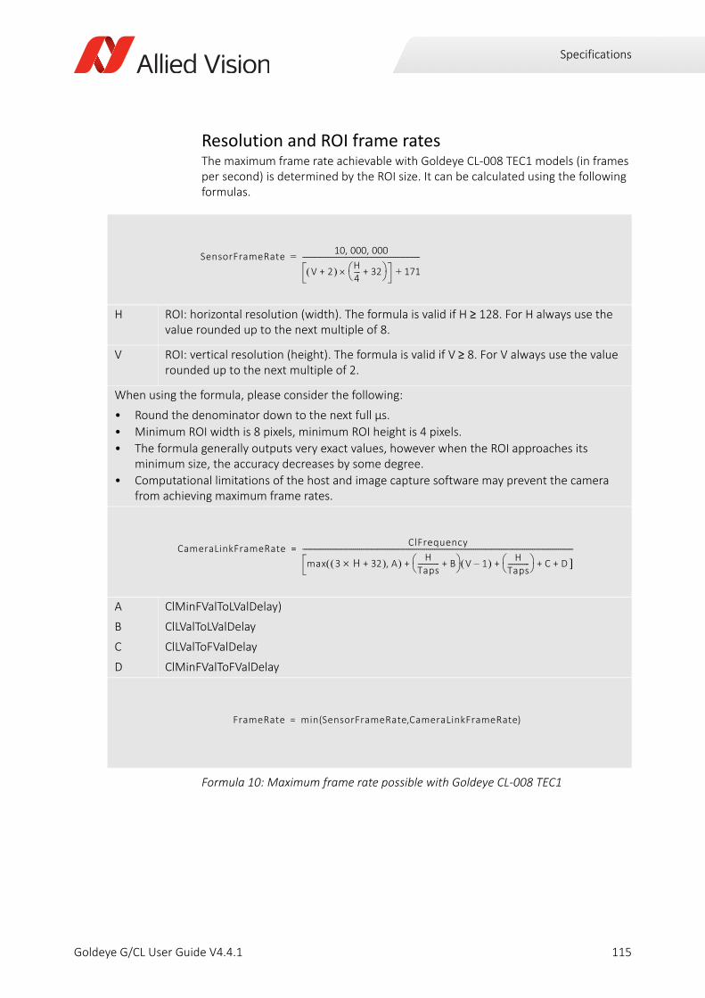
Specifications
Resolution and ROI frame ratesThe maximum frame rate achievable with Goldeye CL-008 TEC1 models (in frames per second) is determined by the ROI size. It can be calculated using the following formulas.
H ROI: horizontal resolution (width). The formula is valid if H ≥ 128. For H always use the value rounded up to the next multiple of 8.
V ROI: vertical resolution (height). The formula is valid if V ≥ 8. For V always use the value rounded up to the next multiple of 2.
When using the formula, please consider the following:
• Round the denominator down to the next full µs.
• Minimum ROI width is 8 pixels, minimum ROI height is 4 pixels.
• The formula generally outputs very exact values, however when the ROI approaches its minimum size, the accuracy decreases by some degree.
• Computational limitations of the host and image capture software may prevent the camera from achieving maximum frame rates.
A
B
C
D
ClMinFValToLValDelay)
ClLValToLValDelay
ClLValToFValDelay
ClMinFValToFValDelay
Formula 10: Maximum frame rate possible with Goldeye CL-008 TEC1
SensorFrameRate10 000 000, ,
V 2+ H4---- 32+ 171+
------------------------------------------------------------------------=
CameraLinkFrameRateClFrequency
max 3 H 32+ A, HTaps------------- B+ V 1– H
Taps------------- C D + + + +
----------------------------------------------------------------------------------------------------------------------------------------------------------------------=
FrameRate min SensorFrameRate CameraLinkFrameRate( , )=
115Goldeye G/CL User Guide V4.4.1
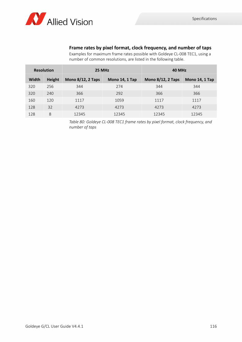
Specifications
Frame rates by pixel format, clock frequency, and number of tapsExamples for maximum frame rates possible with Goldeye CL-008 TEC1, using a number of common resolutions, are listed in the following table.
Resolution 25 MHz 40 MHz
Width Height Mono 8/12, 2 Taps Mono 14, 1 Tap Mono 8/12, 2 Taps Mono 14, 1 Tap
320 256 344 274 344 344
320 240 366 292 366 366
160 120 1117 1059 1117 1117
128 32 4273 4273 4273 4273
128 8 12345 12345 12345 12345
Table 80: Goldeye CL-008 TEC1 frame rates by pixel format, clock frequency, and number of taps
116Goldeye G/CL User Guide V4.4.1

Specifications
Goldeye CL-008 Cool TEC1
Imaging and performance
Parameter Values
Sensor InGaAs, progressive scan, electronic full frame shutter
Sensor type FPA
Spectral range 900 nm to 1700 nm
Resolution 320 (H) × 256 (V)
Pixel size 30 μm × 30 μm
Effective chip size 9.6 mm × 7.68 mm
Dark current (at +5 °C FPA temperature)
160 ke¯/s
Temporal dark noise (Gain0) 420 e¯
Temporal dark noise (Gain1) 170 e¯
Saturation capacity (Gain0) 2.5 Me¯
Saturation capacity (Gain1) 170 ke¯
Dynamic range (Gain0) 75 dB
Dynamic range (Gain1) 60 dB
Pixel operability >99.5%
Max. frame rate at full resolution 344 fps
Exposure time 6 µs to 1250 ms 1
Temperature control Single-stage thermo-electric cooling and heating (TEC1)
Analog gain factor 1 (Gain0), 15 (Gain1)
A/D converter 14-bit
Image buffer size 256 MB
Stream hold capacity 1524 frames at full resolution
1 Maximum exposure value given is valid for Gain0 and sensor temperature of +5°C. Even longer exposures can be set, but the image quality may deteriorate.
Table 81: Goldeye CL-008 Cool TEC1 imaging and performance
117Goldeye G/CL User Guide V4.4.1

Specifications
Output
GPIOs
Mechanics
Parameter Values
Digital interface Camera Link Base, up to 2 taps, 40 MHz, SDR-26 connector, Serial Control Channel
Bit depth 8-bit, 12-bit, 14-bit
Pixel formats • Tap geometry 1X 1Y: Mono 8, Mono 12, Mono 14
• Tap geometry 1X2 1Y: Mono 8, Mono 12
Table 82: Goldeye CL-008 Cool TEC1 output
Parameter Values
Opto-isolated I/Os 1 input, 2 outputs
RS232 up to 115,200 bits per second, 8N1 (adjustable)
LVTTL I/Os 1 input, 1 output
LVDS inputs CC1 - CC4
Table 83: Goldeye CL-008 Cool TEC1 GPIOs
Parameter Values
Body dimensions (L × W × H)without lens adapter
90 × 80 × 80 mm
Lens mounts • C-Mount
• F-Mount and M42-Mount available on request
Mass, without adapter 740 g
Mass, with C-Mount adapter 760 g
Mass, with F-Mount adapter 820 g
Mass, with M42-Mount adapter 780 g
Table 84: Goldeye CL-008 Cool TEC1 mechanics
118Goldeye G/CL User Guide V4.4.1
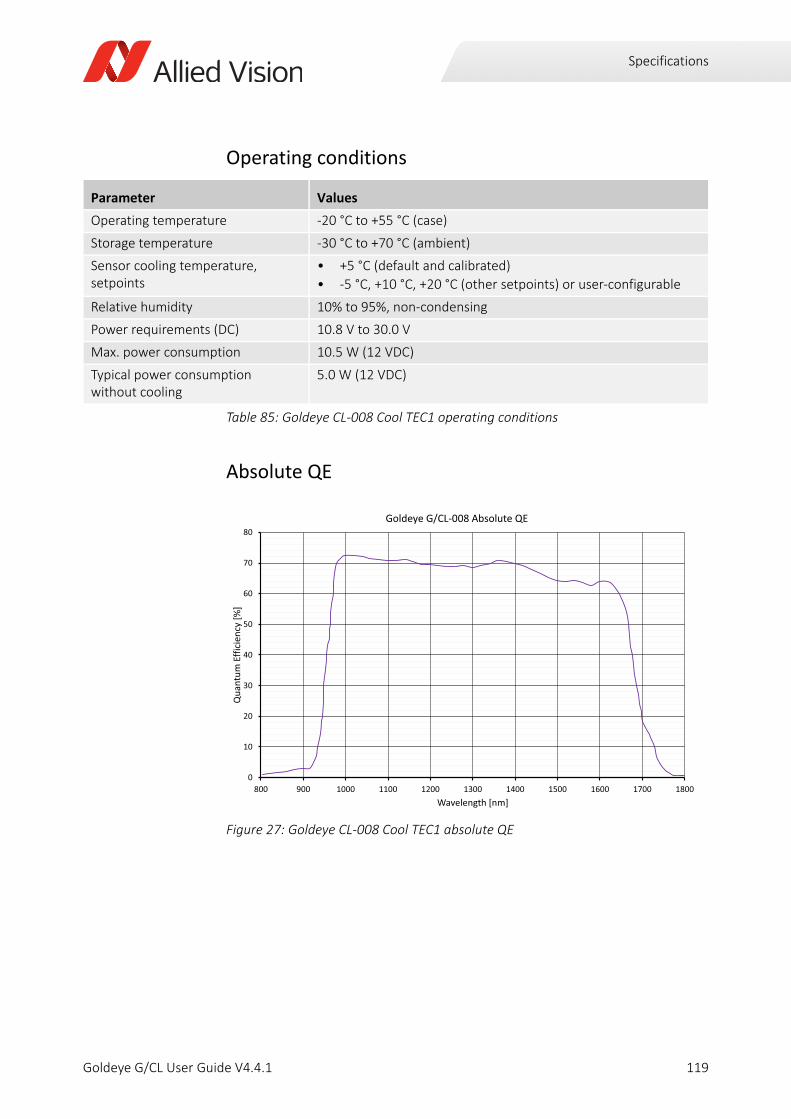
Specifications
Operating conditions
Absolute QE
Parameter Values
Operating temperature -20 °C to +55 °C (case)
Storage temperature -30 °C to +70 °C (ambient)
Sensor cooling temperature, setpoints
• +5 °C (default and calibrated)
• -5 °C, +10 °C, +20 °C (other setpoints) or user-configurable
Relative humidity 10% to 95%, non-condensing
Power requirements (DC) 10.8 V to 30.0 V
Max. power consumption 10.5 W (12 VDC)
Typical power consumption without cooling
5.0 W (12 VDC)
Table 85: Goldeye CL-008 Cool TEC1 operating conditions
Figure 27: Goldeye CL-008 Cool TEC1 absolute QE
0
10
20
30
40
50
60
70
80
800 900 1000 1100 1200 1300 1400 1500 1600 1700 1800
Qua
ntum
Effic
ienc
y[%
]
Wavelength [nm]
Goldeye G/CL 008 Absolute QE
119Goldeye G/CL User Guide V4.4.1
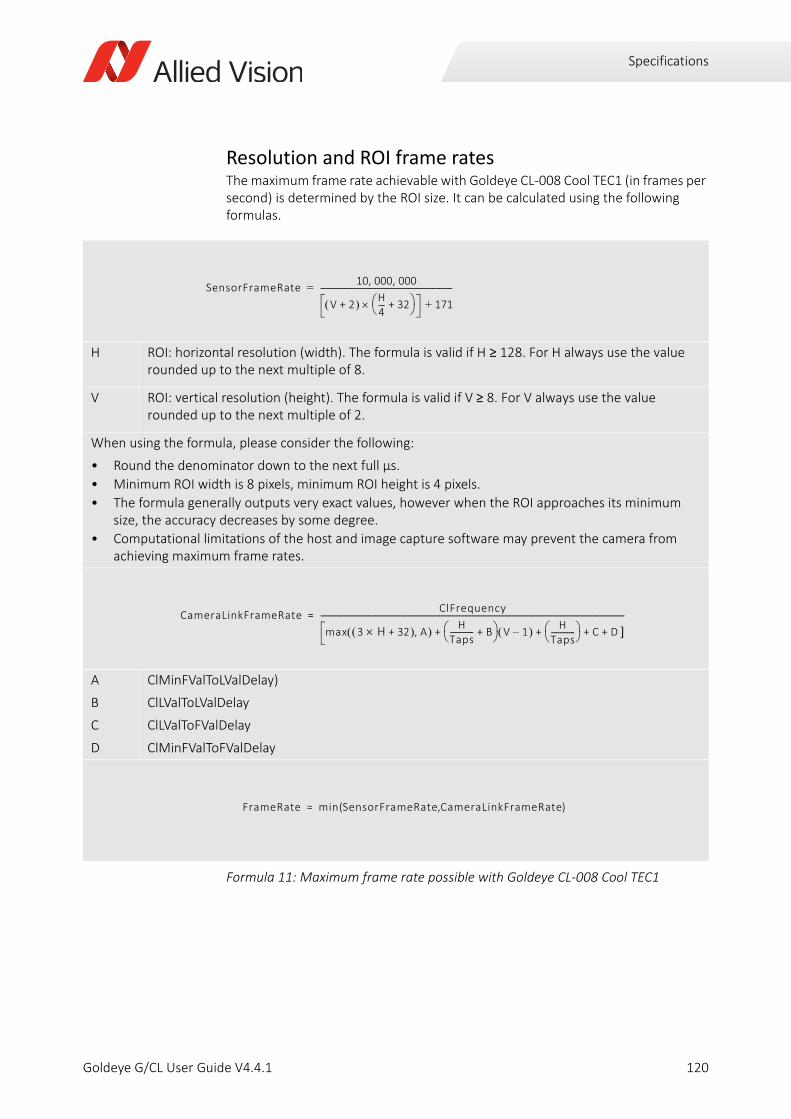
Specifications
Resolution and ROI frame ratesThe maximum frame rate achievable with Goldeye CL-008 Cool TEC1 (in frames per second) is determined by the ROI size. It can be calculated using the following formulas.
H ROI: horizontal resolution (width). The formula is valid if H ≥ 128. For H always use the value rounded up to the next multiple of 8.
V ROI: vertical resolution (height). The formula is valid if V ≥ 8. For V always use the value rounded up to the next multiple of 2.
When using the formula, please consider the following:
• Round the denominator down to the next full µs.
• Minimum ROI width is 8 pixels, minimum ROI height is 4 pixels.
• The formula generally outputs very exact values, however when the ROI approaches its minimum size, the accuracy decreases by some degree.
• Computational limitations of the host and image capture software may prevent the camera from achieving maximum frame rates.
A
B
C
D
ClMinFValToLValDelay)
ClLValToLValDelay
ClLValToFValDelay
ClMinFValToFValDelay
Formula 11: Maximum frame rate possible with Goldeye CL-008 Cool TEC1
SensorFrameRate10 000 000, ,
V 2+ H4---- 32+ 171+
------------------------------------------------------------------------=
CameraLinkFrameRateClFrequency
max 3 H 32+ A, HTaps------------- B+ V 1– H
Taps------------- C D + + + +
----------------------------------------------------------------------------------------------------------------------------------------------------------------------=
FrameRate min SensorFrameRate CameraLinkFrameRate( , )=
120Goldeye G/CL User Guide V4.4.1
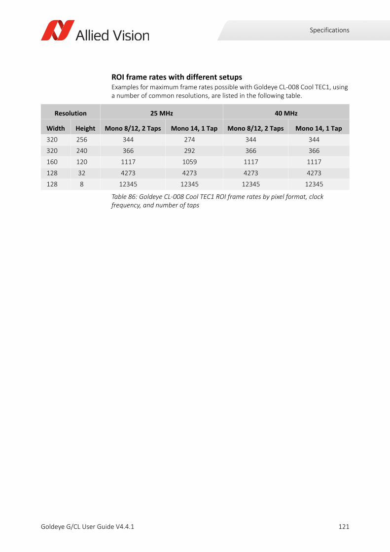
Specifications
ROI frame rates with different setupsExamples for maximum frame rates possible with Goldeye CL-008 Cool TEC1, using a number of common resolutions, are listed in the following table.
Resolution 25 MHz 40 MHz
Width Height Mono 8/12, 2 Taps Mono 14, 1 Tap Mono 8/12, 2 Taps Mono 14, 1 Tap
320 256 344 274 344 344
320 240 366 292 366 366
160 120 1117 1059 1117 1117
128 32 4273 4273 4273 4273
128 8 12345 12345 12345 12345
Table 86: Goldeye CL-008 Cool TEC1 ROI frame rates by pixel format, clock frequency, and number of taps
121Goldeye G/CL User Guide V4.4.1

Specifications
Goldeye CL-030 TEC1
Imaging and performance
Parameter Values
Sensor model Sony IMX991 SenSWIR
Sensor type InGaAs
Sensor format Type 1/4 (4.1 mm diagonal)
Shutter type Global shutter
Spectral range 400 nm to 1700 nm
Resolution 656 (H) × 520 (V)
Pixel size 5 μm × 5 μm
Effective chip size 3.28 mm × 2.6 mm
Dark current (at +20 °C FPA temperature)
4.8 ke¯/s
Temporal dark noise (0 dB) 250 e¯
Temporal dark noise (18 dB) 210 e¯
Saturation capacity (0 dB) 165 ke¯
Saturation capacity (18 dB) 17.2 ke¯
Dynamic range (0 dB) 56.4 dB
Dynamic range (18 dB) 38.2 dB
Pixel operability >99.5%
Exposure time 16 µs to 200 ms 1
Max. frame rate at full resolution 234 fps
Temperature control Single-stage thermo-electric cooling (TEC1)
Analog gain factor 1 (0 dB), 7.9 (18 dB)
A/D converter 12-bit
Image buffer size 256 MB
Stream hold capacity 370 frames at full resolution
1 Maximum exposure value given is valid for 0 dB and sensor temperature of +20°C. Even longer exposures can be set, but the image quality may deteriorate.
Table 87: Goldeye CL-030 TEC1 imaging and performance
122Goldeye G/CL User Guide V4.4.1
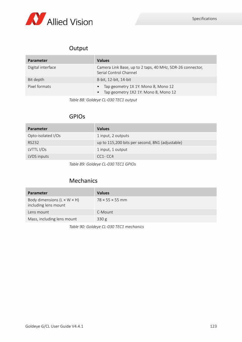
Specifications
Output
GPIOs
Mechanics
Parameter Values
Digital interface Camera Link Base, up to 2 taps, 40 MHz, SDR-26 connector, Serial Control Channel
Bit depth 8-bit, 12-bit, 14-bit
Pixel formats • Tap geometry 1X 1Y: Mono 8, Mono 12
• Tap geometry 1X2 1Y: Mono 8, Mono 12
Table 88: Goldeye CL-030 TEC1 output
Parameter Values
Opto-isolated I/Os 1 input, 2 outputs
RS232 up to 115,200 bits per second, 8N1 (adjustable)
LVTTL I/Os 1 input, 1 output
LVDS inputs CC1 - CC4
Table 89: Goldeye CL-030 TEC1 GPIOs
Parameter Values
Body dimensions (L × W × H)including lens mount
78 × 55 × 55 mm
Lens mount C-Mount
Mass, including lens mount 330 g
Table 90: Goldeye CL-030 TEC1 mechanics
123Goldeye G/CL User Guide V4.4.1

Specifications
Operating conditions
Relative QE
Parameter Values
Operating temperature -20 °C to +55 °C (case)
Storage temperature -30 °C to +70 °C (ambient)
Temperature setpoints1 • +25 °C (default and calibrated)
• +20 °C, +35 °C, +50 °C (other setpoints) or user-configurable
Relative humidity 10% to 95%, non-condensing
Power requirements (DC) 10.8 V to 30.0 V
Max. power consumption 11.8 W (12 VDC)
Typical power consumption without cooling
5.4 W (12 VDC)
Table 91: Goldeye CL-030 TEC1 operating conditions
Figure 28: Goldeye CL-030 TEC1 relative QE
0%
10%
20%
30%
40%
50%
60%
70%
80%
400 500 600 700 800 900 1000 1100 1200 1300 1400 1500 1600 1700 1800
Qua
ntum
Eci
ency
[%]
Wavelength [nm]
Sony IMX990, IMX991 QE
124Goldeye G/CL User Guide V4.4.1
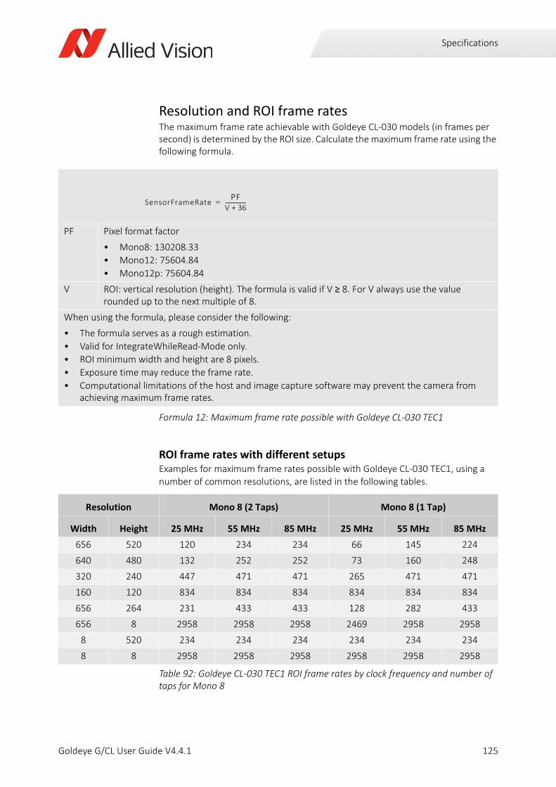
Specifications
Resolution and ROI frame ratesThe maximum frame rate achievable with Goldeye CL-030 models (in frames per second) is determined by the ROI size. Calculate the maximum frame rate using the following formula.
ROI frame rates with different setupsExamples for maximum frame rates possible with Goldeye CL-030 TEC1, using a number of common resolutions, are listed in the following tables.
PF Pixel format factor
• Mono8: 130208.33
• Mono12: 75604.84
• Mono12p: 75604.84
V ROI: vertical resolution (height). The formula is valid if V ≥ 8. For V always use the value rounded up to the next multiple of 8.
When using the formula, please consider the following:
• The formula serves as a rough estimation.
• Valid for IntegrateWhileRead-Mode only.
• ROI minimum width and height are 8 pixels.
• Exposure time may reduce the frame rate.
• Computational limitations of the host and image capture software may prevent the camera from achieving maximum frame rates.
Formula 12: Maximum frame rate possible with Goldeye CL-030 TEC1
Resolution Mono 8 (2 Taps) Mono 8 (1 Tap)
Width Height 25 MHz 55 MHz 85 MHz 25 MHz 55 MHz 85 MHz
656 520 120 234 234 66 145 224
640 480 132 252 252 73 160 248
320 240 447 471 471 265 471 471
160 120 834 834 834 834 834 834
656 264 231 433 433 128 282 433
656 8 2958 2958 2958 2469 2958 2958
8 520 234 234 234 234 234 234
8 8 2958 2958 2958 2958 2958 2958
Table 92: Goldeye CL-030 TEC1 ROI frame rates by clock frequency and number of taps for Mono 8
SensorFrameRatePF
V 36+----------------=
125Goldeye G/CL User Guide V4.4.1
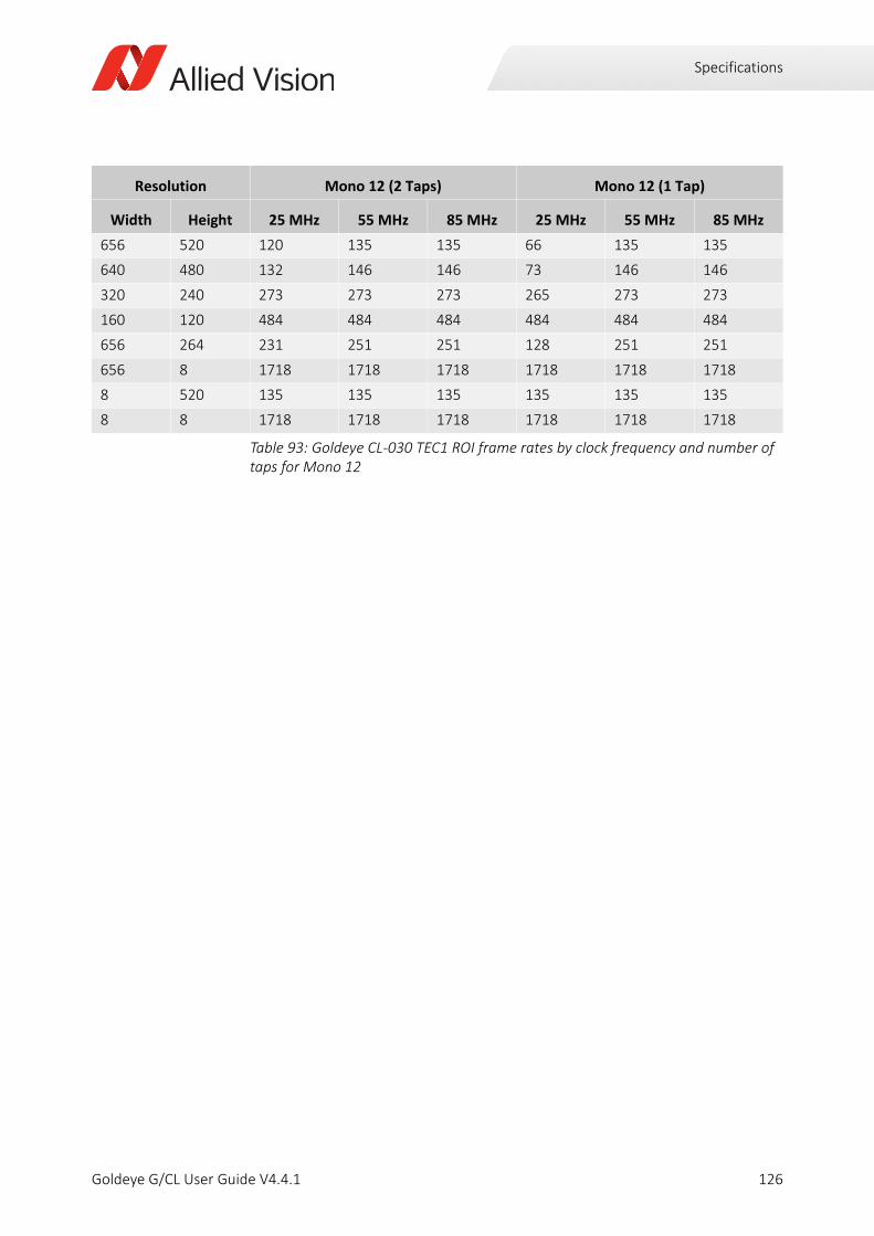
Specifications
Resolution Mono 12 (2 Taps) Mono 12 (1 Tap)
Width Height 25 MHz 55 MHz 85 MHz 25 MHz 55 MHz 85 MHz
656 520 120 135 135 66 135 135
640 480 132 146 146 73 146 146
320 240 273 273 273 265 273 273
160 120 484 484 484 484 484 484
656 264 231 251 251 128 251 251
656 8 1718 1718 1718 1718 1718 1718
8 520 135 135 135 135 135 135
8 8 1718 1718 1718 1718 1718 1718
Table 93: Goldeye CL-030 TEC1 ROI frame rates by clock frequency and number of taps for Mono 12
126Goldeye G/CL User Guide V4.4.1
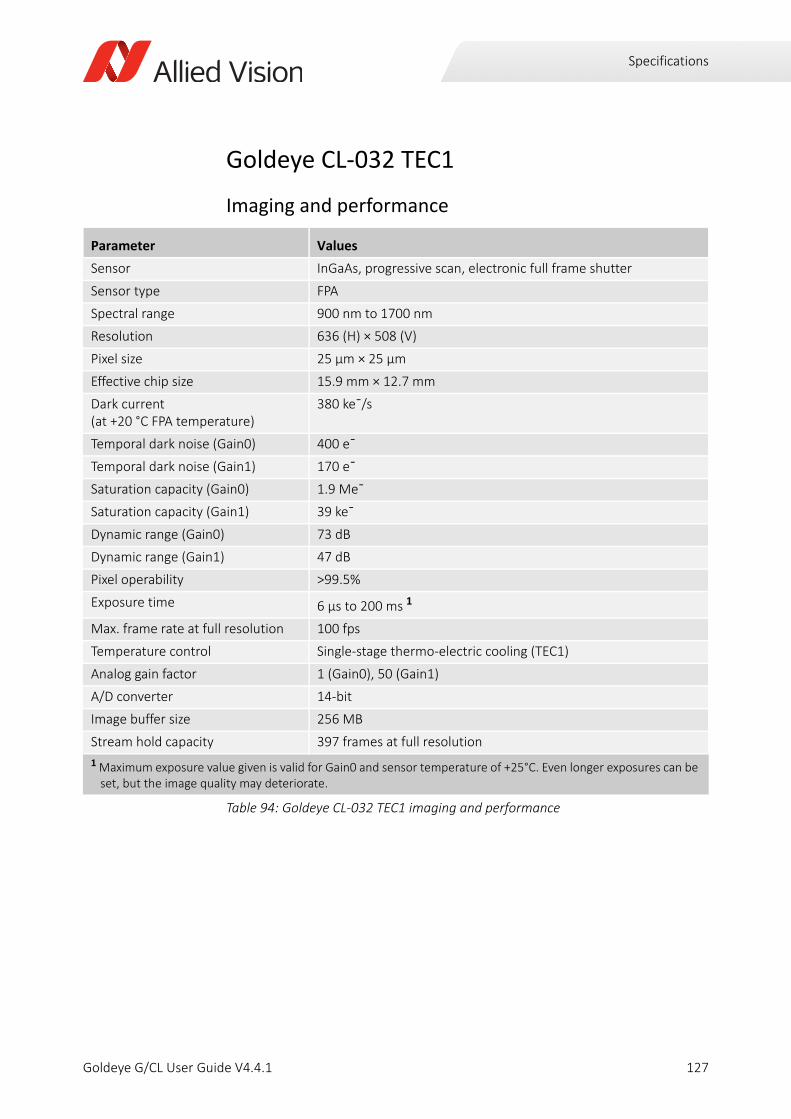
Specifications
Goldeye CL-032 TEC1
Imaging and performance
Parameter Values
Sensor InGaAs, progressive scan, electronic full frame shutter
Sensor type FPA
Spectral range 900 nm to 1700 nm
Resolution 636 (H) × 508 (V)
Pixel size 25 μm × 25 μm
Effective chip size 15.9 mm × 12.7 mm
Dark current (at +20 °C FPA temperature)
380 ke¯/s
Temporal dark noise (Gain0) 400 e¯
Temporal dark noise (Gain1) 170 e¯
Saturation capacity (Gain0) 1.9 Me¯
Saturation capacity (Gain1) 39 ke¯
Dynamic range (Gain0) 73 dB
Dynamic range (Gain1) 47 dB
Pixel operability >99.5%
Exposure time 6 µs to 200 ms 1
Max. frame rate at full resolution 100 fps
Temperature control Single-stage thermo-electric cooling (TEC1)
Analog gain factor 1 (Gain0), 50 (Gain1)
A/D converter 14-bit
Image buffer size 256 MB
Stream hold capacity 397 frames at full resolution
1 Maximum exposure value given is valid for Gain0 and sensor temperature of +25°C. Even longer exposures can be set, but the image quality may deteriorate.
Table 94: Goldeye CL-032 TEC1 imaging and performance
127Goldeye G/CL User Guide V4.4.1
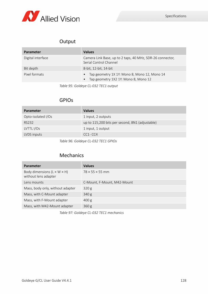
Specifications
Output
GPIOs
Mechanics
Parameter Values
Digital interface Camera Link Base, up to 2 taps, 40 MHz, SDR-26 connector, Serial Control Channel
Bit depth 8-bit, 12-bit, 14-bit
Pixel formats • Tap geometry 1X 1Y: Mono 8, Mono 12, Mono 14
• Tap geometry 1X2 1Y: Mono 8, Mono 12
Table 95: Goldeye CL-032 TEC1 output
Parameter Values
Opto-isolated I/Os 1 input, 2 outputs
RS232 up to 115,200 bits per second, 8N1 (adjustable)
LVTTL I/Os 1 input, 1 output
LVDS inputs CC1 - CC4
Table 96: Goldeye CL-032 TEC1 GPIOs
Parameter Values
Body dimensions (L × W × H)without lens adapter
78 × 55 × 55 mm
Lens mounts C-Mount, F-Mount, M42-Mount
Mass, body only, without adapter 320 g
Mass, with C-Mount adapter 340 g
Mass, with F-Mount adapter 400 g
Mass, with M42-Mount adapter 360 g
Table 97: Goldeye CL-032 TEC1 mechanics
128Goldeye G/CL User Guide V4.4.1

Specifications
Operating conditions
Absolute QE
Parameter Values
Operating temperature -20 °C to +55 °C (case)
Storage temperature -30 °C to +70 °C (ambient)
Sensor cooling temperature, setpoints
• +20 °C (default and calibrated)
• +5 °C, +35 °C, +50 °C (other setpoints) or user-configurable
Relative humidity 10% to 95%, non-condensing
Power requirements (DC) 10.8 V to 30.0 V
Max. power consumption 10 W (12 VDC)
Typical power consumption without cooling
4.5 W (12 VDC)
Table 98: Goldeye CL-032 TEC1 operating conditions
Figure 29: Goldeye CL-032 TEC1 absolute QE
0
10
20
30
40
50
60
70
80
800 900 1000 1100 1200 1300 1400 1500 1600 1700 1800
Qua
ntum
Effic
ienc
y[%
]
Wavelength [nm]
Goldeye G/CL 032 Absolute QE
129Goldeye G/CL User Guide V4.4.1

Specifications
Resolution and ROI frame ratesThe maximum frame rate achievable with Goldeye CL-032 models (in frames per second) is determined by the ROI size. Calculate the maximum frame rate using the following formula.
H ROI: horizontal resolution (width). The formula is valid if H ≥ 128. For H always use the value rounded up to the next multiple of 16.
V ROI: vertical resolution (height). The formula is valid if V ≥ 8. For V always use the value rounded up to the next multiple of 4.
When using the formula, please consider the following:
• Round the denominator down to the next full µs.
• Minimum ROI width is 8 pixels, minimum ROI height is 4 pixels.
• The formula generally outputs very exact values, however when the ROI approaches its minimum size, the accuracy decreases by some degree.
• Computational limitations of the host and image capture software may prevent the camera from achieving maximum frame rates.
A
B
C
D
ClMinFValToLValDelay)
ClLValToLValDelay
ClLValToFValDelay
ClMinFValToFValDelay
Formula 13: Maximum frame rate possible with Goldeye CL-032 TEC1
SensorFrameRate10 000 000, ,
V 4+ H4---- 32+ 131+
------------------------------------------------------------------------=
CameraLinkFrameRateClFrequency
max 3 H 32+ A, HTaps------------- B+ V 1– H
Taps------------- C D + + + +
----------------------------------------------------------------------------------------------------------------------------------------------------------------------=
FrameRate min SensorFrameRate CameraLinkFrameRate( , )=
130Goldeye G/CL User Guide V4.4.1
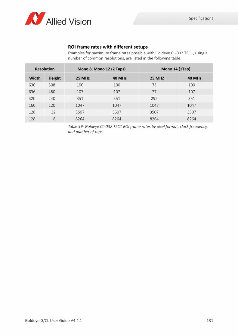
Specifications
ROI frame rates with different setupsExamples for maximum frame rates possible with Goldeye CL-032 TEC1, using a number of common resolutions, are listed in the following table.
Resolution Mono 8, Mono 12 (2 Taps) Mono 14 (1Tap)
Width Height 25 MHz 40 MHz 25 MHZ 40 MHz
636 508 100 100 73 100
636 480 107 107 77 107
320 240 351 351 292 351
160 120 1047 1047 1047 1047
128 32 3507 3507 3507 3507
128 8 8264 8264 8264 8264
Table 99: Goldeye CL-032 TEC1 ROI frame rates by pixel format, clock frequency, and number of taps
131Goldeye G/CL User Guide V4.4.1
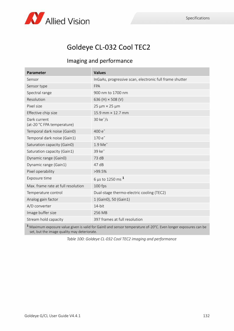
Specifications
Goldeye CL-032 Cool TEC2
Imaging and performance
Parameter Values
Sensor InGaAs, progressive scan, electronic full frame shutter
Sensor type FPA
Spectral range 900 nm to 1700 nm
Resolution 636 (H) × 508 (V)
Pixel size 25 μm × 25 μm
Effective chip size 15.9 mm × 12.7 mm
Dark current (at -20 °C FPA temperature)
30 ke¯/s
Temporal dark noise (Gain0) 400 e¯
Temporal dark noise (Gain1) 170 e¯
Saturation capacity (Gain0) 1.9 Me¯
Saturation capacity (Gain1) 39 ke¯
Dynamic range (Gain0) 73 dB
Dynamic range (Gain1) 47 dB
Pixel operability >99.5%
Exposure time 6 µs to 1250 ms 1
Max. frame rate at full resolution 100 fps
Temperature control Dual-stage thermo-electric cooling (TEC2)
Analog gain factor 1 (Gain0), 50 (Gain1)
A/D converter 14-bit
Image buffer size 256 MB
Stream hold capacity 397 frames at full resolution
1 Maximum exposure value given is valid for Gain0 and sensor temperature of -20°C. Even longer exposures can be set, but the image quality may deteriorate.
Table 100: Goldeye CL-032 Cool TEC2 imaging and performance
132Goldeye G/CL User Guide V4.4.1
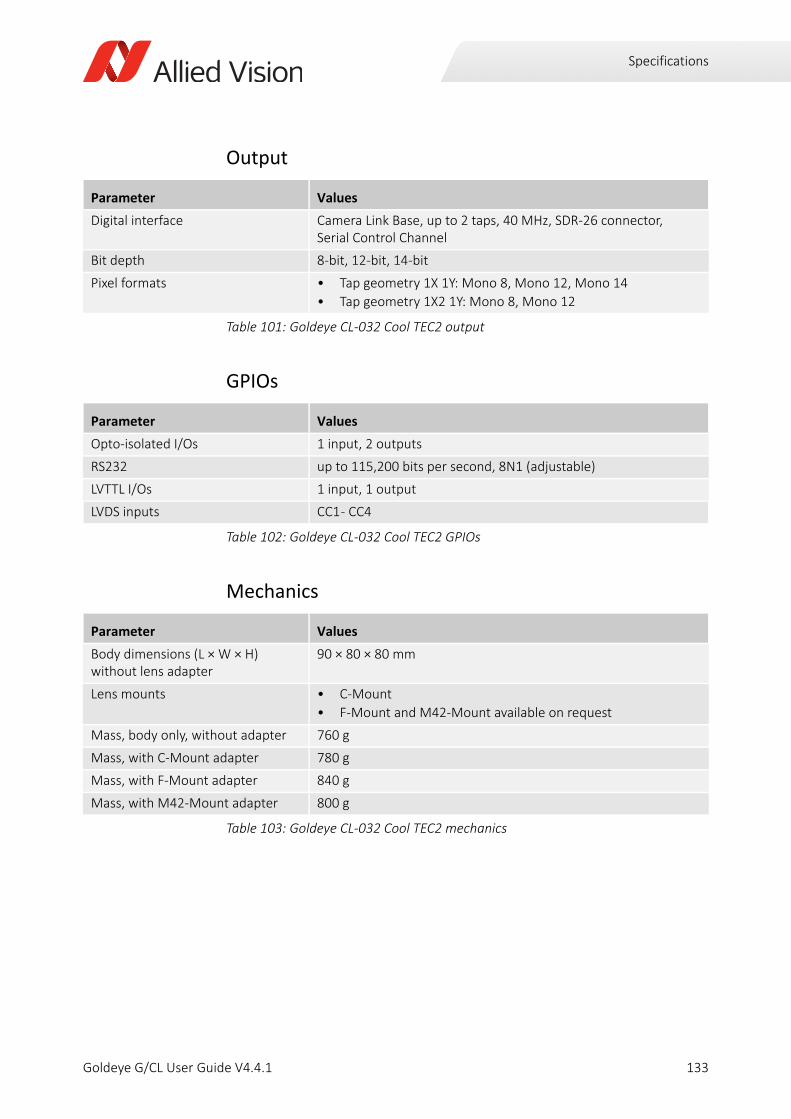
Specifications
Output
GPIOs
Mechanics
Parameter Values
Digital interface Camera Link Base, up to 2 taps, 40 MHz, SDR-26 connector, Serial Control Channel
Bit depth 8-bit, 12-bit, 14-bit
Pixel formats • Tap geometry 1X 1Y: Mono 8, Mono 12, Mono 14
• Tap geometry 1X2 1Y: Mono 8, Mono 12
Table 101: Goldeye CL-032 Cool TEC2 output
Parameter Values
Opto-isolated I/Os 1 input, 2 outputs
RS232 up to 115,200 bits per second, 8N1 (adjustable)
LVTTL I/Os 1 input, 1 output
LVDS inputs CC1 - CC4
Table 102: Goldeye CL-032 Cool TEC2 GPIOs
Parameter Values
Body dimensions (L × W × H)without lens adapter
90 × 80 × 80 mm
Lens mounts • C-Mount
• F-Mount and M42-Mount available on request
Mass, body only, without adapter 760 g
Mass, with C-Mount adapter 780 g
Mass, with F-Mount adapter 840 g
Mass, with M42-Mount adapter 800 g
Table 103: Goldeye CL-032 Cool TEC2 mechanics
133Goldeye G/CL User Guide V4.4.1

Specifications
Operating conditions
Absolute QE
Parameter Values
Operating temperature -20 °C to +55 °C (case)
Storage temperature -30 °C to +70 °C (ambient)
Sensor cooling temperature, setpoints
• -25 °C (default and calibrated)
• -5 °C, +10 °C (other setpoints) or user-configurable
Relative humidity 10% to 95%, non-condensing
Power requirements 10.8 V to 10.8 VDC
Max. power consumption 19 W (12 VDC)
Typical power consumption without cooling
5.5 W (12 VDC)
Table 104: Goldeye CL-032 Cool TEC2 operating conditions
Figure 30: Goldeye CL-032 Cool TEC2 absolute QE
0
10
20
30
40
50
60
70
80
800 900 1000 1100 1200 1300 1400 1500 1600 1700 1800
Qua
ntum
Effic
ienc
y[%
]
Wavelength [nm]
Goldeye G/CL 032 Absolute QE
134Goldeye G/CL User Guide V4.4.1

Specifications
Resolution and ROI frame ratesThe maximum frame rate achievable with Goldeye CL-032 Cool TEC2 (in frames per second) is determined by the ROI size. Calculate the maximum frame rate using the following formula.
H ROI: horizontal resolution (width). The formula is valid if H ≥ 128. For H always use the value rounded up to the next multiple of 16.
V ROI: vertical resolution (height). The formula is valid if V ≥ 8. For V always use the value rounded up to the next multiple of 4.
When using the formula, please consider the following:
• Round the denominator down to the next full µs.
• Minimum ROI width is 8 pixels, minimum ROI height is 4 pixels.
• The formula generally outputs very exact values, however when the ROI approaches its minimum size, the accuracy decreases by some degree.
• Computational limitations of the host and image capture software may prevent the camera from achieving maximum frame rates.
A
B
C
D
ClMinFValToLValDelay)
ClLValToLValDelay
ClLValToFValDelay
ClMinFValToFValDelay
Formula 14: Maximum frame rate possible with Goldeye CL-032 Cool TEC2
SensorFrameRate10 000 000, ,
V 4+ H4---- 32+ 131+
------------------------------------------------------------------------=
CameraLinkFrameRateClFrequency
max 3 H 32+ A, HTaps------------- B+ V 1– H
Taps------------- C D + + + +
----------------------------------------------------------------------------------------------------------------------------------------------------------------------=
FrameRate min SensorFrameRate CameraLinkFrameRate( , )=
135Goldeye G/CL User Guide V4.4.1
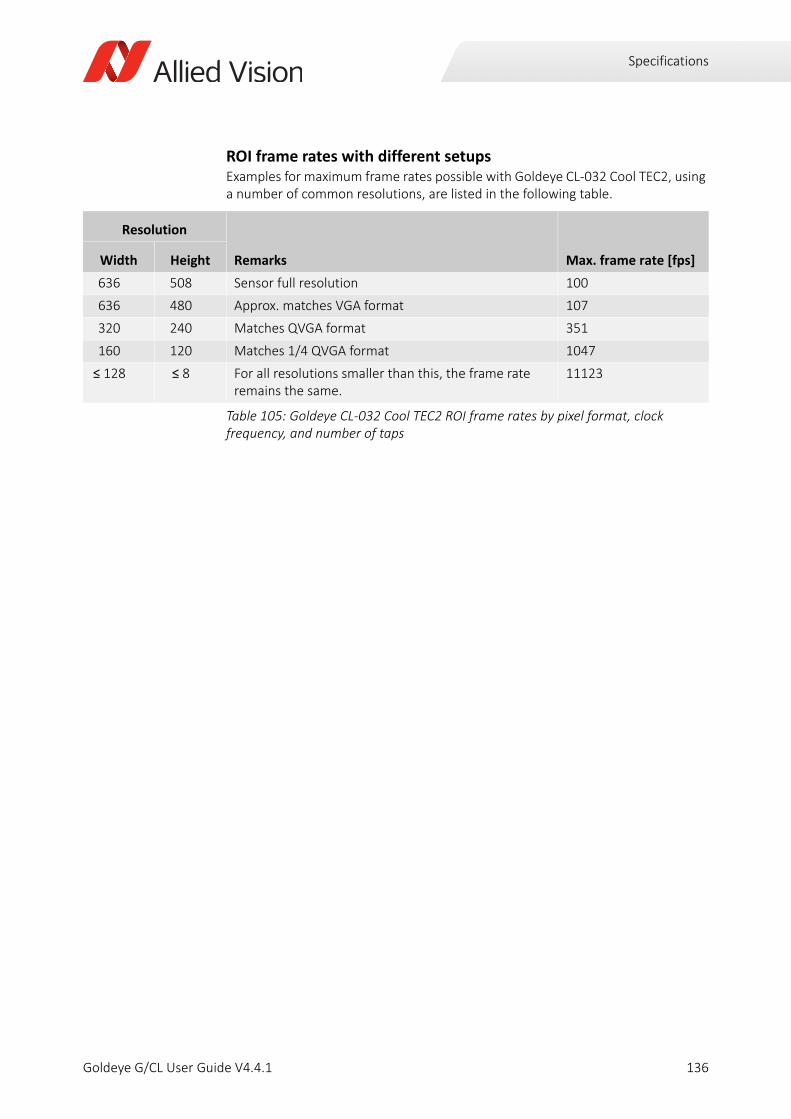
Specifications
ROI frame rates with different setupsExamples for maximum frame rates possible with Goldeye CL-032 Cool TEC2, using a number of common resolutions, are listed in the following table.
Resolution
Remarks Max. frame rate [fps]Width Height
636 508 Sensor full resolution 100
636 480 Approx. matches VGA format 107
320 240 Matches QVGA format 351
160 120 Matches 1/4 QVGA format 1047
≤ 128 ≤ 8 For all resolutions smaller than this, the frame rate remains the same.
11123
Table 105: Goldeye CL-032 Cool TEC2 ROI frame rates by pixel format, clock frequency, and number of taps
136Goldeye G/CL User Guide V4.4.1
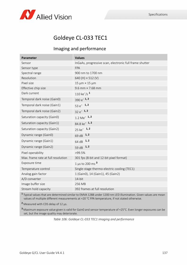
Specifications
Goldeye CL-033 TEC1
Imaging and performance
Parameter Values
Sensor InGaAs, progressive scan, electronic full frame shutter
Sensor type FPA
Spectral range 900 nm to 1700 nm
Resolution 640 (H) × 512 (V)
Pixel size 15 μm × 15 μm
Effective chip size 9.6 mm × 7.68 mm
Dark current 110 ke¯/s 1
Temporal dark noise (Gain0) 390 e¯ 1, 2
Temporal dark noise (Gain1) 53 e¯ 1, 2
Temporal dark noise (Gain2) 32 e¯ 1, 2
Saturation capacity (Gain0) 1.2 Me¯ 1, 2
Saturation capacity (Gain1) 84.8 ke¯ 1, 2
Saturation capacity (Gain2) 25 ke¯ 1, 2
Dynamic range (Gain0) 69 dB 1, 2
Dynamic range (Gain1) 64 dB 1, 2
Dynamic range (Gain2) 59 dB 1, 2
Pixel operability >99.5%
Max. frame rate at full resolution 301 fps (8-bit and 12-bit pixel format)
Exposure time 1 µs to 200 ms 3
Temperature control Single-stage thermo-electric cooling (TEC1)
Analog gain factor 1 (Gain0), 14 (Gain1), 45 (Gain2)
A/D converter 14-bit
Image buffer size 256 MB
Stream hold capacity 392 frames at full resolution
1 Typical values that are determined similar to EMVA 1288 under 1200 nm LED illumination. Given values are mean values of multiple different measurements at +20 °C FPA temperature, if not stated otherwise.
2 Measured with CDS delay of 12 µs.
3 Maximum exposure value given is valid for Gain0 and sensor temperature of +25°C. Even longer exposures can be set, but the image quality may deteriorate.
Table 106: Goldeye CL-033 TEC1 imaging and performance
137Goldeye G/CL User Guide V4.4.1
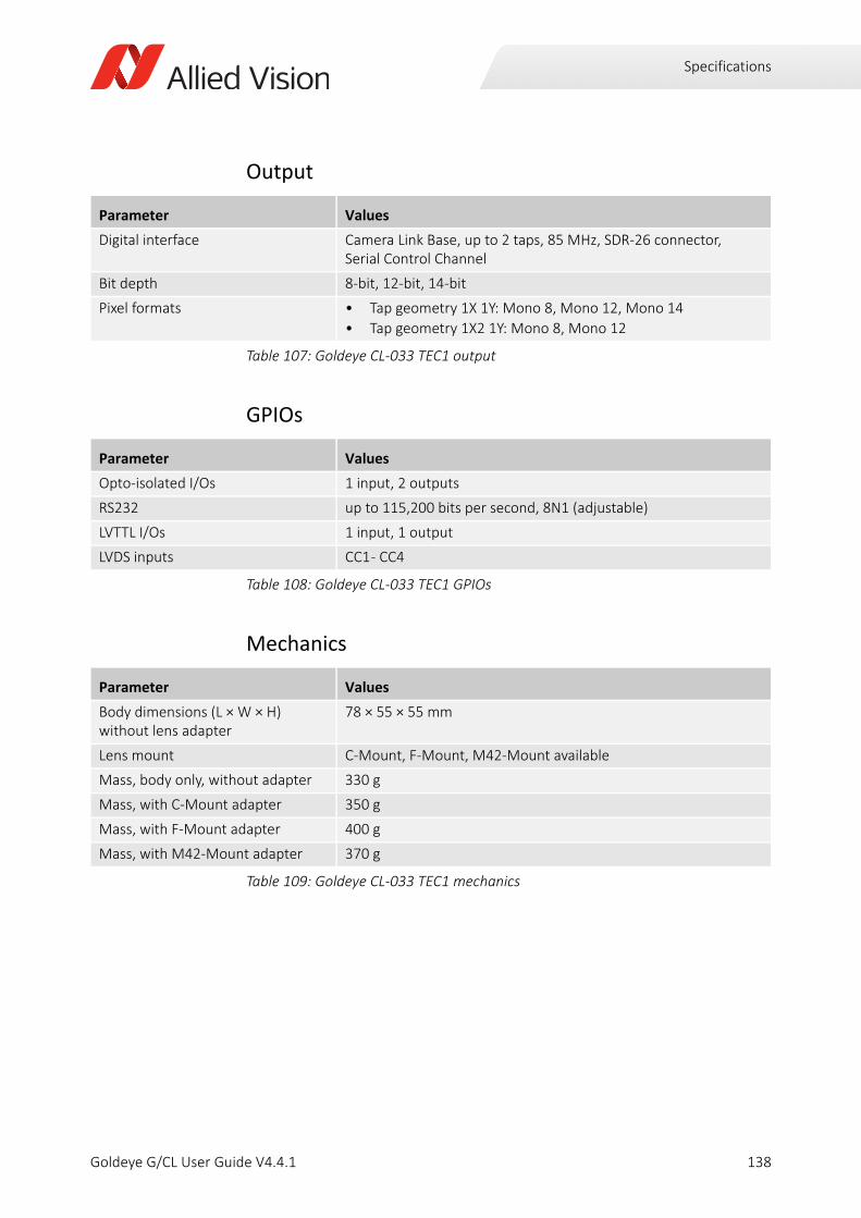
Specifications
Output
GPIOs
Mechanics
Parameter Values
Digital interface Camera Link Base, up to 2 taps, 85 MHz, SDR-26 connector, Serial Control Channel
Bit depth 8-bit, 12-bit, 14-bit
Pixel formats • Tap geometry 1X 1Y: Mono 8, Mono 12, Mono 14
• Tap geometry 1X2 1Y: Mono 8, Mono 12
Table 107: Goldeye CL-033 TEC1 output
Parameter Values
Opto-isolated I/Os 1 input, 2 outputs
RS232 up to 115,200 bits per second, 8N1 (adjustable)
LVTTL I/Os 1 input, 1 output
LVDS inputs CC1 - CC4
Table 108: Goldeye CL-033 TEC1 GPIOs
Parameter Values
Body dimensions (L × W × H)without lens adapter
78 × 55 × 55 mm
Lens mount C-Mount, F-Mount, M42-Mount available
Mass, body only, without adapter 330 g
Mass, with C-Mount adapter 350 g
Mass, with F-Mount adapter 400 g
Mass, with M42-Mount adapter 370 g
Table 109: Goldeye CL-033 TEC1 mechanics
138Goldeye G/CL User Guide V4.4.1

Specifications
Operating conditions
Absolute QE
Parameter Values
Operating temperature -20 °C to +55 °C (case)
Storage temperature -30 °C to +70 °C (ambient)
Sensor cooling temperature, setpoints
• +20 °C (default and calibrated)
• +5 °C, +35 °C, +50 °C (other setpoints) or user-configurable
Relative humidity 10% to 95%, non-condensing
Power requirements 10.8 VDC to 30.0 VDC
Max. power consumption 11.8 W (12 VDC)
Typical power consumption without cooling
6.3 W (12 VDC)
Table 110: Goldeye CL-033 TEC1 operating conditions
Figure 31: Goldeye CL-033 TEC1 absolute QE
0
10
20
30
40
50
60
70
80
90
800 900 1000 1100 1200 1300 1400 1500 1600 1700 1800
Qua
ntum
Effic
ienc
y[%
]
Wavelength [nm]
Goldeye G/CL 033 Absolute QE
139Goldeye G/CL User Guide V4.4.1

Specifications
Resolution and ROI frame rateThe maximum frame rate achievable with Goldeye CL-033 TEC1 (in frames per second) is determined by the ROI size. Calculate the maximum frame rate using the following formula.
H ROI: horizontal resolution (width). The formula is valid if H ≥ 128. For H always use the value rounded up to the next multiple of 32.
V ROI: vertical resolution (height). The formula is valid if V ≥ 8. For V always use the value rounded up to the next multiple of 4.
When using the formula, please consider the following:
• Round the denominator up or down to the next full µs.
• Minimum ROI width is 8 pixels, minimum ROI height is 4 pixels.
• The formula generally outputs very exact values, however when the ROI approaches its minimum size, the accuracy decreases by some degree.
• Computational limitations of the host and image capture software may prevent the camera from achieving maximum frame rates.
A
B
C
D
ClMinFValToLValDelay)
ClLValToLValDelay
ClLValToFValDelay
ClMinFValToFValDelay
Formula 15: Maximum frame rate possible with Goldeye CL-033 TEC1
SensorFrameRate18 000 000, ,
V 1+ H8---- 36+ 254+
------------------------------------------------------------------------=
CameraLinkFrameRateClFrequency
max 3 H 32+ A, HTaps------------- B+ V 1– H
Taps------------- C D + + + +
----------------------------------------------------------------------------------------------------------------------------------------------------------------------=
FrameRate min SensorFrameRate CameraLinkFrameRate( , )=
140Goldeye G/CL User Guide V4.4.1

Specifications
ROI frame rates with different setupsExamples for maximum frame rates possible with the Goldeye CL-033 TEC1, using a number of common resolutions, are listed in the following table.
Resolution Mono 8, Mono 12 (2 Taps) Mono 14 (1Tap)
Width Height 25 MHz 55 MHz 85 MHz 25 MHz 55 MHz 85 MHz
640 512 125 276 301 68 151 234
640 480 134 295 321 73 161 250
320 256 428 251 909 251 553 855
320 240 456 268 968 268 590 912
160 120 1404 912 2557 912 2004 2557
128 32 5524 3802 9174 3802 8333 9174
128 8 17241 12658 25000 12658 25000 25000
Table 111: Goldeye CL-033 TEC1 ROI frame rates by pixel format, clock frequency, and number of taps
141Goldeye G/CL User Guide V4.4.1
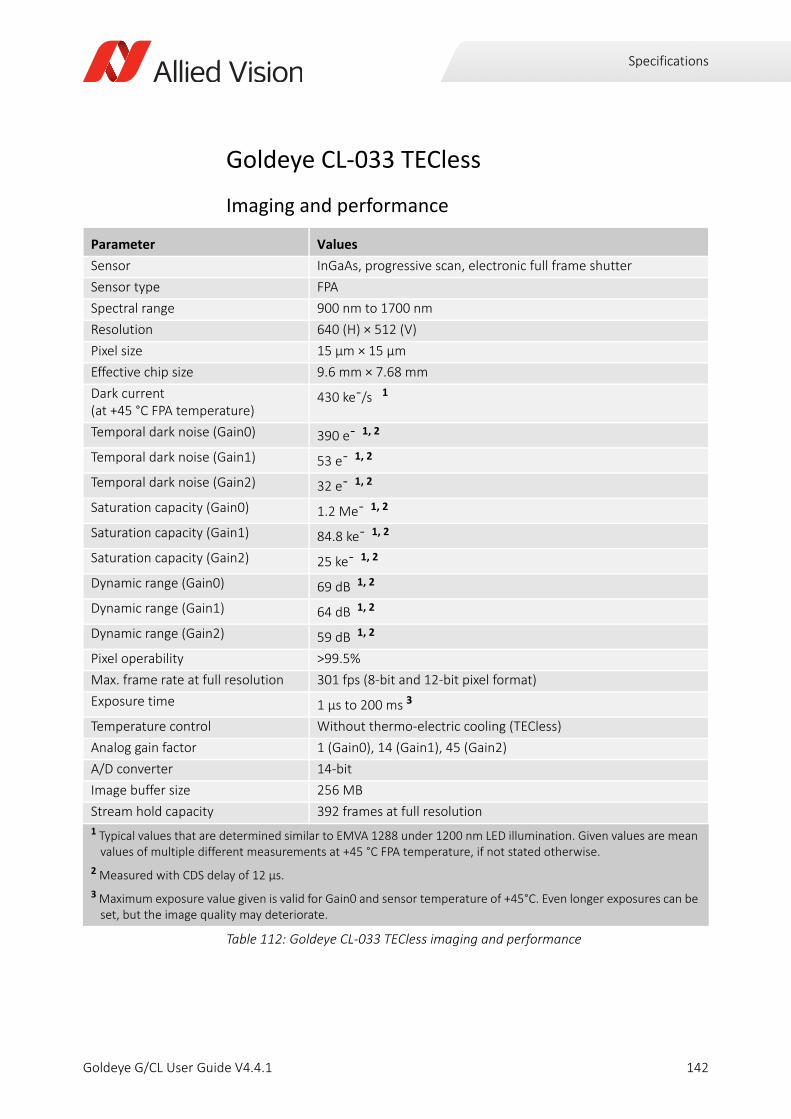
Specifications
Goldeye CL-033 TECless
Imaging and performance
Parameter Values
Sensor InGaAs, progressive scan, electronic full frame shutter
Sensor type FPA
Spectral range 900 nm to 1700 nm
Resolution 640 (H) × 512 (V)
Pixel size 15 μm × 15 μm
Effective chip size 9.6 mm × 7.68 mm
Dark current (at +45 °C FPA temperature)
430 ke¯/s 1
Temporal dark noise (Gain0) 390 e¯ 1, 2
Temporal dark noise (Gain1) 53 e¯ 1, 2
Temporal dark noise (Gain2) 32 e¯ 1, 2
Saturation capacity (Gain0) 1.2 Me¯ 1, 2
Saturation capacity (Gain1) 84.8 ke¯ 1, 2
Saturation capacity (Gain2) 25 ke¯ 1, 2
Dynamic range (Gain0) 69 dB 1, 2
Dynamic range (Gain1) 64 dB 1, 2
Dynamic range (Gain2) 59 dB 1, 2
Pixel operability >99.5%
Max. frame rate at full resolution 301 fps (8-bit and 12-bit pixel format)
Exposure time 1 µs to 200 ms 3
Temperature control Without thermo-electric cooling (TECless)
Analog gain factor 1 (Gain0), 14 (Gain1), 45 (Gain2)
A/D converter 14-bit
Image buffer size 256 MB
Stream hold capacity 392 frames at full resolution
1 Typical values that are determined similar to EMVA 1288 under 1200 nm LED illumination. Given values are mean values of multiple different measurements at +45 °C FPA temperature, if not stated otherwise.
2 Measured with CDS delay of 12 µs.
3 Maximum exposure value given is valid for Gain0 and sensor temperature of +45°C. Even longer exposures can be set, but the image quality may deteriorate.
Table 112: Goldeye CL-033 TECless imaging and performance
142Goldeye G/CL User Guide V4.4.1

Specifications
Output
GPIO
Mechanics
Parameter Values
Digital interface Camera Link Base, up to 2 taps, 85 MHz, SDR-26 connector, Serial Control Channel
Bit depth 8-bit, 12-bit, 14-bit
Pixel formats • Tap geometry 1X 1Y: Mono 8, Mono 12, Mono 14
• Tap geometry 1X2 1Y: Mono 8, Mono 12
Table 113: Goldeye CL-033 TECless output
Parameter Values
Opto-isolated I/Os 1 input, 2 outputs
RS232 up to 115,200 bits per second, 8N1 (adjustable)
LVTTL I/Os 1 input, 1 output
LVDS inputs CC1 - CC4
Table 114: Goldeye CL-033 TECless GPIOs
Parameter Values
Body dimensions (L × W × H)without lens adapter
78 × 55 × 55 mm
Lens mounts • C-Mount
• F-Mount and M42-Mount available on request
Mass, body only, without adapter 300 g
Mass, with C-Mount adapter 320 g
Mass, with F-Mount adapter 370 g
Mass, with M42-Mount adapter 340 g
Table 115: Goldeye CL-033 TECless mechanics
143Goldeye G/CL User Guide V4.4.1

Specifications
Operating conditions
Absolute QE
Parameter Values
Operating temperature -20 °C to +55 °C (case)
Storage temperature -30 °C to +70 °C (ambient)
Sensor cooling temperature, setpoints
Not applicable to TECless models.
Relative humidity 10% to 95%, non-condensing
Power requirements 10.8 VDC to 30.0 VDC
Max. power consumption 6.0 W (12 VDC)
Typical power consumption 6.0 W (12 VDC)
Table 116: Goldeye CL-033 TECless operating conditions
Figure 32: Goldeye CL-033 TECless absolute QE
0
10
20
30
40
50
60
70
80
90
800 900 1000 1100 1200 1300 1400 1500 1600 1700 1800
Qua
ntum
Effic
ienc
y[%
]
Wavelength [nm]
Goldeye G/CL 033 Absolute QE
144Goldeye G/CL User Guide V4.4.1
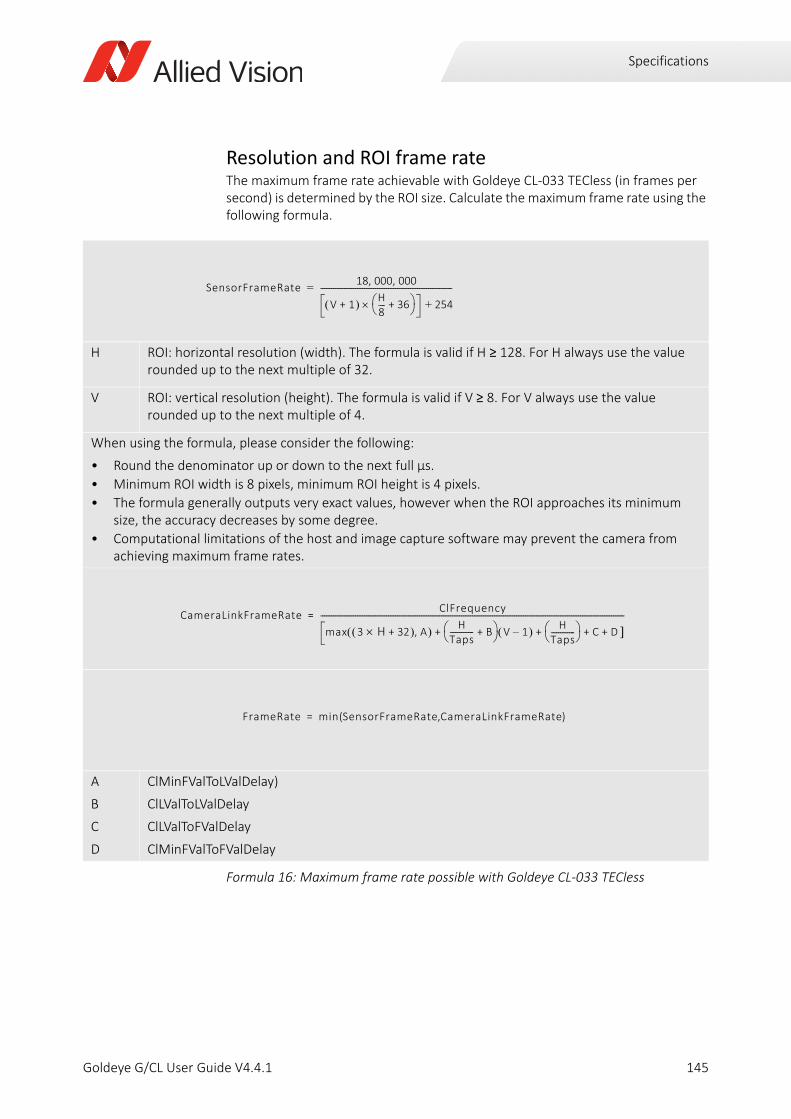
Specifications
Resolution and ROI frame rateThe maximum frame rate achievable with Goldeye CL-033 TECless (in frames per second) is determined by the ROI size. Calculate the maximum frame rate using the following formula.
H ROI: horizontal resolution (width). The formula is valid if H ≥ 128. For H always use the value rounded up to the next multiple of 32.
V ROI: vertical resolution (height). The formula is valid if V ≥ 8. For V always use the value rounded up to the next multiple of 4.
When using the formula, please consider the following:
• Round the denominator up or down to the next full µs.
• Minimum ROI width is 8 pixels, minimum ROI height is 4 pixels.
• The formula generally outputs very exact values, however when the ROI approaches its minimum size, the accuracy decreases by some degree.
• Computational limitations of the host and image capture software may prevent the camera from achieving maximum frame rates.
A
B
C
D
ClMinFValToLValDelay)
ClLValToLValDelay
ClLValToFValDelay
ClMinFValToFValDelay
Formula 16: Maximum frame rate possible with Goldeye CL-033 TECless
SensorFrameRate18 000 000, ,
V 1+ H8---- 36+ 254+
------------------------------------------------------------------------=
CameraLinkFrameRateClFrequency
max 3 H 32+ A, HTaps------------- B+ V 1– H
Taps------------- C D + + + +
----------------------------------------------------------------------------------------------------------------------------------------------------------------------=
FrameRate min SensorFrameRate CameraLinkFrameRate( , )=
145Goldeye G/CL User Guide V4.4.1

Specifications
ROI frame rates with different setupsExamples for maximum frame rates possible with Goldeye CL-033 TECless, using a number of common resolutions, are listed in the following table.
Resolution Mono 8, Mono 12 (2 Taps) Mono 14 (1Tap)
Width Height 25 MHz 55 MHz 85 MHz 25 MHz 55 MHz 85 MHz
640 512 125 276 301 68 151 234
640 480 134 295 321 73 161 250
320 256 428 251 909 251 553 855
320 240 456 268 968 268 590 912
160 120 1404 912 2557 912 2004 2557
128 32 5524 3802 9174 3802 8333 9174
128 8 17241 12658 25000 12658 25000 25000
Table 117: Goldeye CL-033 TECless ROI frame rates by pixel format, clock frequency, and number of taps
146Goldeye G/CL User Guide V4.4.1

Specifications
Goldeye CL-034 TEC1
Imaging and performance
Parameter Values
Sensor InGaAs, progressive scan, electronic full frame shutter
Sensor type FPA
Spectral range 900 nm to 1700 nm
Resolution 636 (H) × 508 (V)
Pixel size 15 μm × 15 μm
Effective chip size 9.6 mm × 7.68 mm
Dark current 49 ke¯/s 1
Temporal dark noise (Gain0) 390 e¯ 1, 2
Temporal dark noise (Gain1) 53 e¯ 1, 2
Temporal dark noise (Gain2) 32 e¯ 1, 2
Saturation capacity (Gain0) 1.2 Me¯ 1, 2
Saturation capacity (Gain1) 84.8 ke¯ 1, 2
Saturation capacity (Gain2) 25 ke¯ 1, 2
Dynamic range (Gain0) 69 dB 1, 2
Dynamic range (Gain1) 64 dB 1, 2
Dynamic range (Gain2) 59 dB 1, 2
Pixel operability >99.5%
Max. frame rate at full resolution 303 fps (8-bit and 12-bit pixel format)
Exposure time 1 µs to 200 ms 3
Temperature control Single-stage thermo-electric cooling (TEC1)
Analog gain factor 1 (Gain0), 14 (Gain1), 45 (Gain2)
A/D converter 14-bit
Image buffer size 256 MB
Stream hold capacity 392 frames at full resolution
1 Typical values that are determined similar to EMVA 1288 under 1200 nm LED illumination. Given values are mean values of multiple different measurements at +20 °C FPA temperature, if not stated otherwise.
2 Measured with CDS delay of 12 µs.
3 Maximum exposure value given is valid for Gain0 and sensor temperature of +25°C. Even longer exposures can be set, but the image quality may deteriorate.
Table 118: Goldeye CL-034 TEC1 imaging and performance
147Goldeye G/CL User Guide V4.4.1

Specifications
Output
GPIOs
Mechanics
Parameter Values
Digital interface Camera Link Base, up to 2 taps, 85 MHz, SDR-26 connector, Serial Control Channel
Bit depth 8-bit, 12-bit, 14-bit
Pixel formats • Tap geometry 1X 1Y: Mono 8, Mono 12, Mono 14
• Tap geometry 1X2 1Y: Mono 8, Mono 12
Table 119: Goldeye CL-034 TEC1 output
Parameter Values
Opto-isolated I/Os 1 input, 2 outputs
RS232 up to 115,200 bits per second, 8N1 (adjustable)
LVTTL I/Os 1 input, 1 output
LVDS inputs CC1 - CC4
Table 120: Goldeye CL-034 TEC1 GPIOs
Parameter Values
Body dimensions (L × W × H)without lens adapter
78 × 55 × 55 mm
Lens mounts C-Mount, F-Mount, M42-Mount
Mass, body only, without adapter 330 g
Mass, with C-Mount adapter 350 g
Mass, with F-Mount adapter 400 g
Mass, with M42-Mount adapter 370 g
Table 121: Goldeye CL-034 TEC1 mechanics
148Goldeye G/CL User Guide V4.4.1

Specifications
Operating conditions
Absolute QE
Parameter Values
Operating temperature -20 °C to +55 °C (case)
Storage temperature -30 °C to +70 °C (ambient)
Sensor cooling temperature, setpoints
• +20 °C (default and calibrated)
• +5 °C, +35 °C, +50 °C (other setpoints) or user-configurable
Relative humidity 10% to 95%, non-condensing
Power requirements (DC) 10.8 V to 30.0 V
Max. power consumption 11.8 W (12 VDC)
Typical power consumption without cooling
6.3 W (12 VDC)
Table 122: Goldeye CL-034 TEC1 operating conditions
Figure 33: Goldeye CL-034 TEC1 absolute QE
0
10
20
30
40
50
60
70
80
90
800 900 1000 1100 1200 1300 1400 1500 1600 1700 1800
Qua
ntum
Effic
ienc
y[%
]
Wavelength [nm]
Goldeye G/CL 034 Absolute QE
149Goldeye G/CL User Guide V4.4.1
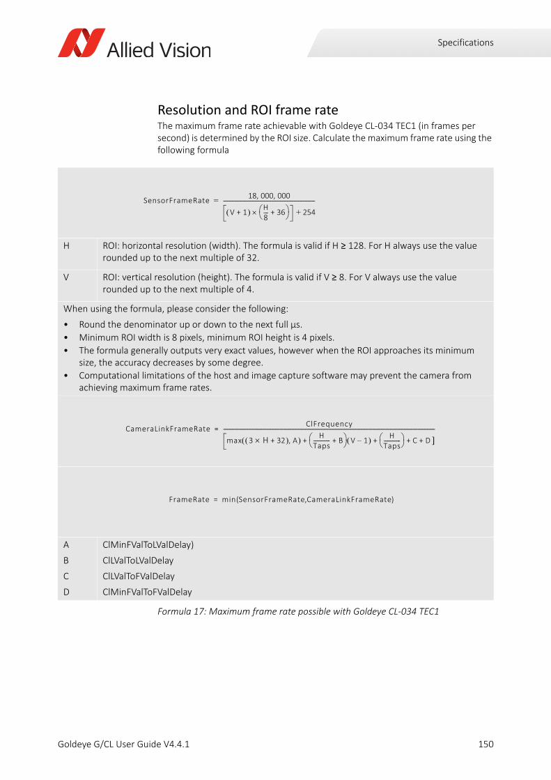
Specifications
Resolution and ROI frame rateThe maximum frame rate achievable with Goldeye CL-034 TEC1 (in frames per second) is determined by the ROI size. Calculate the maximum frame rate using the following formula
H ROI: horizontal resolution (width). The formula is valid if H ≥ 128. For H always use the value rounded up to the next multiple of 32.
V ROI: vertical resolution (height). The formula is valid if V ≥ 8. For V always use the value rounded up to the next multiple of 4.
When using the formula, please consider the following:
• Round the denominator up or down to the next full µs.
• Minimum ROI width is 8 pixels, minimum ROI height is 4 pixels.
• The formula generally outputs very exact values, however when the ROI approaches its minimum size, the accuracy decreases by some degree.
• Computational limitations of the host and image capture software may prevent the camera from achieving maximum frame rates.
A
B
C
D
ClMinFValToLValDelay)
ClLValToLValDelay
ClLValToFValDelay
ClMinFValToFValDelay
Formula 17: Maximum frame rate possible with Goldeye CL-034 TEC1
SensorFrameRate18 000 000, ,
V 1+ H8---- 36+ 254+
------------------------------------------------------------------------=
CameraLinkFrameRateClFrequency
max 3 H 32+ A, HTaps------------- B+ V 1– H
Taps------------- C D + + + +
----------------------------------------------------------------------------------------------------------------------------------------------------------------------=
FrameRate min SensorFrameRate CameraLinkFrameRate( , )=
150Goldeye G/CL User Guide V4.4.1
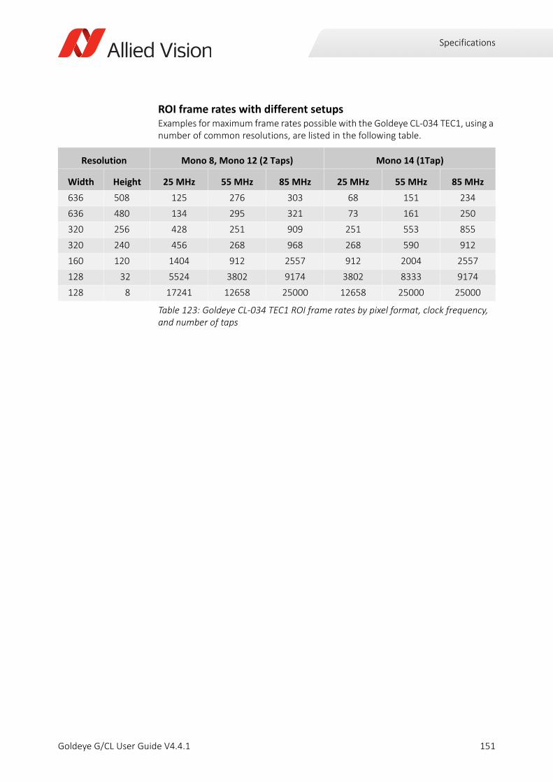
Specifications
ROI frame rates with different setupsExamples for maximum frame rates possible with the Goldeye CL-034 TEC1, using a number of common resolutions, are listed in the following table.
Resolution Mono 8, Mono 12 (2 Taps) Mono 14 (1Tap)
Width Height 25 MHz 55 MHz 85 MHz 25 MHz 55 MHz 85 MHz
636 508 125 276 303 68 151 234
636 480 134 295 321 73 161 250
320 256 428 251 909 251 553 855
320 240 456 268 968 268 590 912
160 120 1404 912 2557 912 2004 2557
128 32 5524 3802 9174 3802 8333 9174
128 8 17241 12658 25000 12658 25000 25000
Table 123: Goldeye CL-034 TEC1 ROI frame rates by pixel format, clock frequency, and number of taps
151Goldeye G/CL User Guide V4.4.1
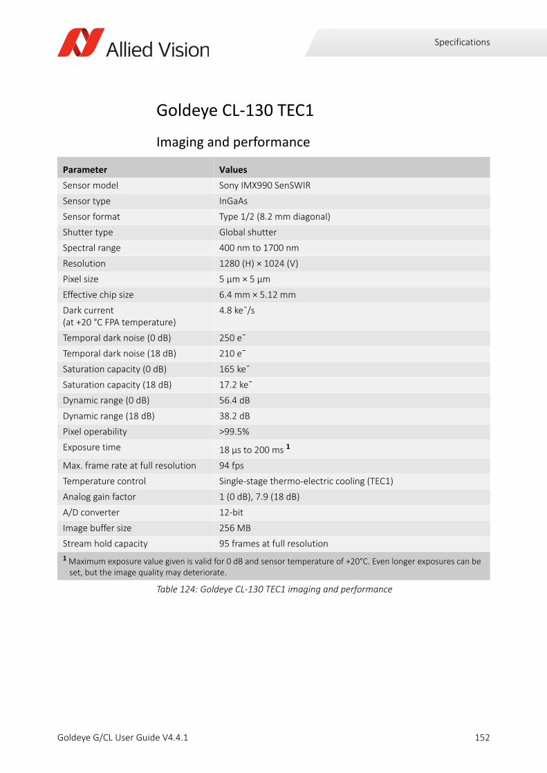
Specifications
Goldeye CL-130 TEC1
Imaging and performance
Parameter Values
Sensor model Sony IMX990 SenSWIR
Sensor type InGaAs
Sensor format Type 1/2 (8.2 mm diagonal)
Shutter type Global shutter
Spectral range 400 nm to 1700 nm
Resolution 1280 (H) × 1024 (V)
Pixel size 5 μm × 5 μm
Effective chip size 6.4 mm × 5.12 mm
Dark current (at +20 °C FPA temperature)
4.8 ke¯/s
Temporal dark noise (0 dB) 250 e¯
Temporal dark noise (18 dB) 210 e¯
Saturation capacity (0 dB) 165 ke¯
Saturation capacity (18 dB) 17.2 ke¯
Dynamic range (0 dB) 56.4 dB
Dynamic range (18 dB) 38.2 dB
Pixel operability >99.5%
Exposure time 18 µs to 200 ms 1
Max. frame rate at full resolution 94 fps
Temperature control Single-stage thermo-electric cooling (TEC1)
Analog gain factor 1 (0 dB), 7.9 (18 dB)
A/D converter 12-bit
Image buffer size 256 MB
Stream hold capacity 95 frames at full resolution
1 Maximum exposure value given is valid for 0 dB and sensor temperature of +20°C. Even longer exposures can be set, but the image quality may deteriorate.
Table 124: Goldeye CL-130 TEC1 imaging and performance
152Goldeye G/CL User Guide V4.4.1
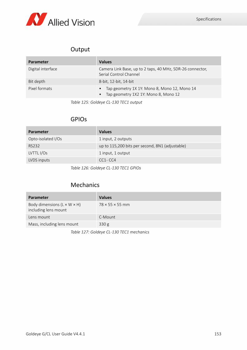
Specifications
Output
GPIOs
Mechanics
Parameter Values
Digital interface Camera Link Base, up to 2 taps, 40 MHz, SDR-26 connector, Serial Control Channel
Bit depth 8-bit, 12-bit, 14-bit
Pixel formats • Tap geometry 1X 1Y: Mono 8, Mono 12, Mono 14
• Tap geometry 1X2 1Y: Mono 8, Mono 12
Table 125: Goldeye CL-130 TEC1 output
Parameter Values
Opto-isolated I/Os 1 input, 2 outputs
RS232 up to 115,200 bits per second, 8N1 (adjustable)
LVTTL I/Os 1 input, 1 output
LVDS inputs CC1 - CC4
Table 126: Goldeye CL-130 TEC1 GPIOs
Parameter Values
Body dimensions (L × W × H)including lens mount
78 × 55 × 55 mm
Lens mount C-Mount
Mass, including lens mount 330 g
Table 127: Goldeye CL-130 TEC1 mechanics
153Goldeye G/CL User Guide V4.4.1
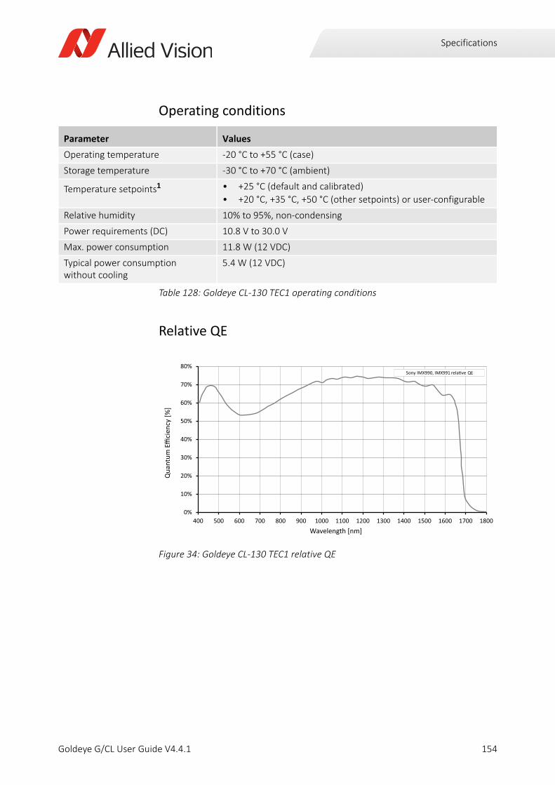
Specifications
Operating conditions
Relative QE
Parameter Values
Operating temperature -20 °C to +55 °C (case)
Storage temperature -30 °C to +70 °C (ambient)
Temperature setpoints1 • +25 °C (default and calibrated)
• +20 °C, +35 °C, +50 °C (other setpoints) or user-configurable
Relative humidity 10% to 95%, non-condensing
Power requirements (DC) 10.8 V to 30.0 V
Max. power consumption 11.8 W (12 VDC)
Typical power consumption without cooling
5.4 W (12 VDC)
Table 128: Goldeye CL-130 TEC1 operating conditions
Figure 34: Goldeye CL-130 TEC1 relative QE
0%
10%
20%
30%
40%
50%
60%
70%
80%
400 500 600 700 800 900 1000 1100 1200 1300 1400 1500 1600 1700 1800
Qua
ntum
Eci
ency
[%]
Wavelength [nm]
Sony IMX990, IMX991 QE
154Goldeye G/CL User Guide V4.4.1
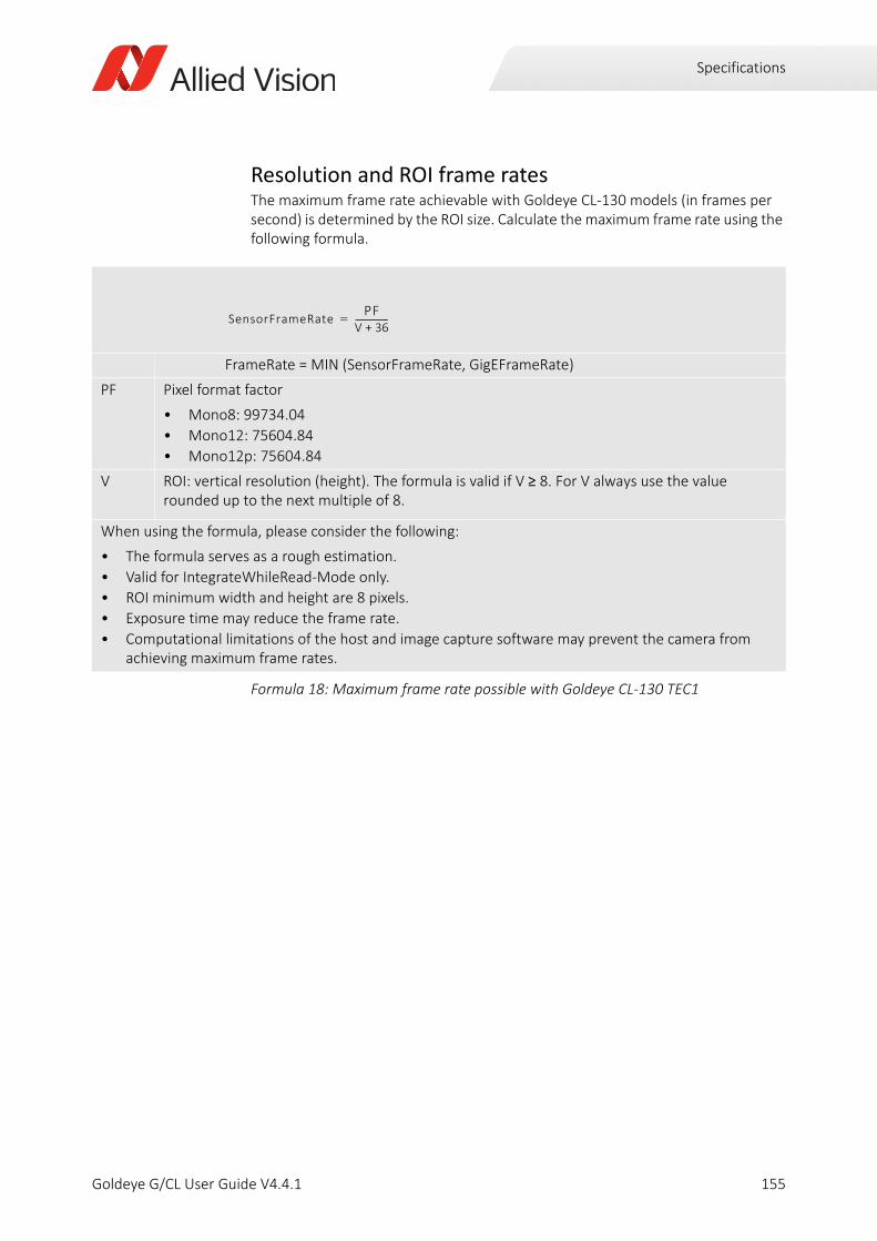
Specifications
Resolution and ROI frame ratesThe maximum frame rate achievable with Goldeye CL-130 models (in frames per second) is determined by the ROI size. Calculate the maximum frame rate using the following formula.
FrameRate = MIN (SensorFrameRate, GigEFrameRate)
PF Pixel format factor
• Mono8: 99734.04
• Mono12: 75604.84
• Mono12p: 75604.84
V ROI: vertical resolution (height). The formula is valid if V ≥ 8. For V always use the value rounded up to the next multiple of 8.
When using the formula, please consider the following:
• The formula serves as a rough estimation.
• Valid for IntegrateWhileRead-Mode only.
• ROI minimum width and height are 8 pixels.
• Exposure time may reduce the frame rate.
• Computational limitations of the host and image capture software may prevent the camera from achieving maximum frame rates.
Formula 18: Maximum frame rate possible with Goldeye CL-130 TEC1
SensorFrameRatePF
V 36+----------------=
155Goldeye G/CL User Guide V4.4.1
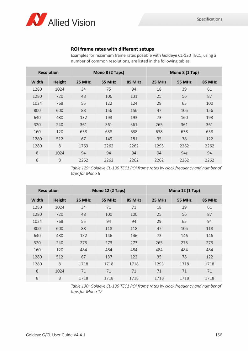
Specifications
ROI frame rates with different setupsExamples for maximum frame rates possible with Goldeye CL-130 TEC1, using a number of common resolutions, are listed in the following tables.
Resolution Mono 8 (2 Taps) Mono 8 (1 Tap)
Width Height 25 MHz 55 MHz 85 MHz 25 MHz 55 MHz 85 MHz
1280 1024 34 75 94 18 39 61
1280 720 48 106 131 25 56 87
1024 768 55 122 124 29 65 100
800 600 88 156 156 47 105 156
640 480 132 193 193 73 160 193
320 240 361 361 361 265 361 361
160 120 638 638 638 638 638 638
1280 512 67 149 181 35 78 122
1280 8 1763 2262 2262 1293 2262 2262
8 1024 94 94 94 94 94z 94
8 8 2262 2262 2262 2262 2262 2262
Table 129: Goldeye CL-130 TEC1 ROI frame rates by clock frequency and number of taps for Mono 8
Resolution Mono 12 (2 Taps) Mono 12 (1 Tap)
Width Height 25 MHz 55 MHz 85 MHz 25 MHz 55 MHz 85 MHz
1280 1024 34 71 71 18 39 61
1280 720 48 100 100 25 56 87
1024 768 55 94 94 29 65 94
800 600 88 118 118 47 105 118
640 480 132 146 146 73 146 146
320 240 273 273 273 265 273 273
160 120 484 484 484 484 484 484
1280 512 67 137 122 35 78 122
1280 8 1718 1718 1718 1293 1718 1718
8 1024 71 71 71 71 71 71
8 8 1718 1718 1718 1718 1718 1718
Table 130: Goldeye CL-130 TEC1 ROI frame rates by clock frequency and number of taps for Mono 12
156Goldeye G/CL User Guide V4.4.1
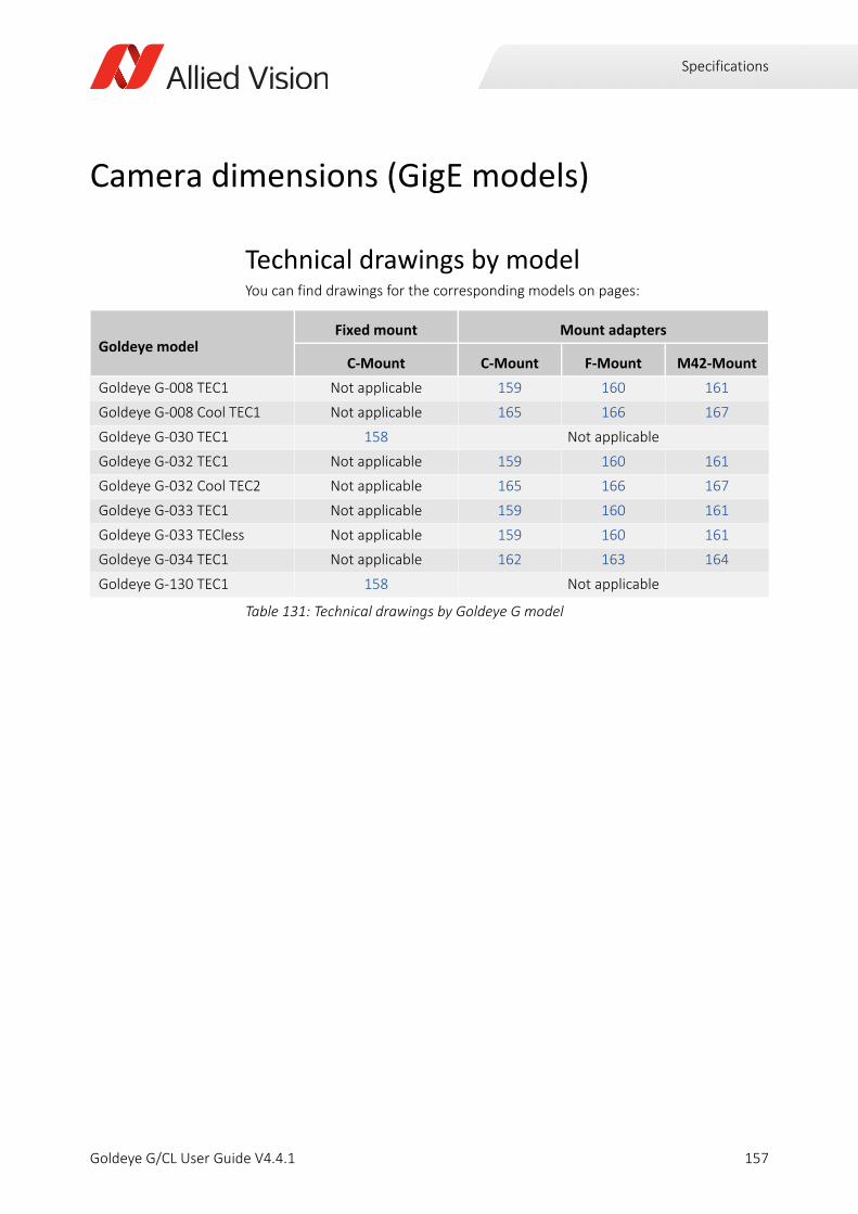
Specifications
Camera dimensions (GigE models)
Technical drawings by modelYou can find drawings for the corresponding models on pages:
Goldeye modelFixed mount Mount adapters
C-Mount C-Mount F-Mount M42-Mount
Goldeye G-008 TEC1 Not applicable 159 160 161
Goldeye G-008 Cool TEC1 Not applicable 165 166 167
Goldeye G-030 TEC1 158 Not applicable
Goldeye G-032 TEC1 Not applicable 159 160 161
Goldeye G-032 Cool TEC2 Not applicable 165 166 167
Goldeye G-033 TEC1 Not applicable 159 160 161
Goldeye G-033 TECless Not applicable 159 160 161
Goldeye G-034 TEC1 Not applicable 162 163 164
Goldeye G-130 TEC1 158 Not applicable
Table 131: Technical drawings by Goldeye G model
157Goldeye G/CL User Guide V4.4.1
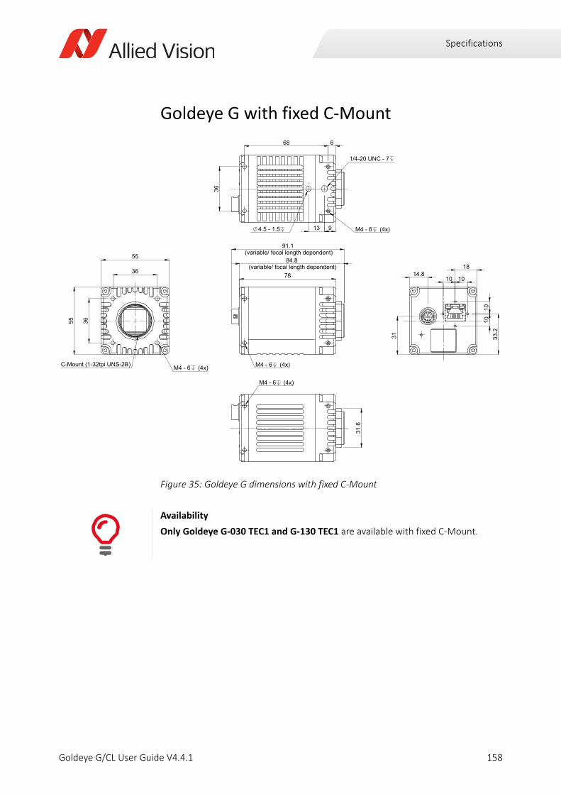
Specifications
Goldeye G with fixed C-Mount
Figure 35: Goldeye G dimensions with fixed C-Mount
Availability
Only Goldeye G-030 TEC1 and G-130 TEC1 are available with fixed C-Mount.
158Goldeye G/CL User Guide V4.4.1
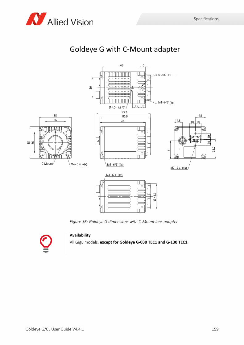
Specifications
Goldeye G with C-Mount adapter
Figure 36: Goldeye G dimensions with C-Mount lens adapter
Availability
All GigE models, except for Goldeye G-030 TEC1 and G-130 TEC1.
7886.993.2
M4 - 6 (4x)
55
55
36
36
M4 - 6 (4x)C-Mount
14.8
1010
33.2
31
18
10 10
M2 - 5 (4x)
36
68 6
9
1/4-20 UNC - 8
M4 - 6 (4x)13Ø 4.5 - 1.5
M4 - 6 (4x)
Ø43
.9
159Goldeye G/CL User Guide V4.4.1
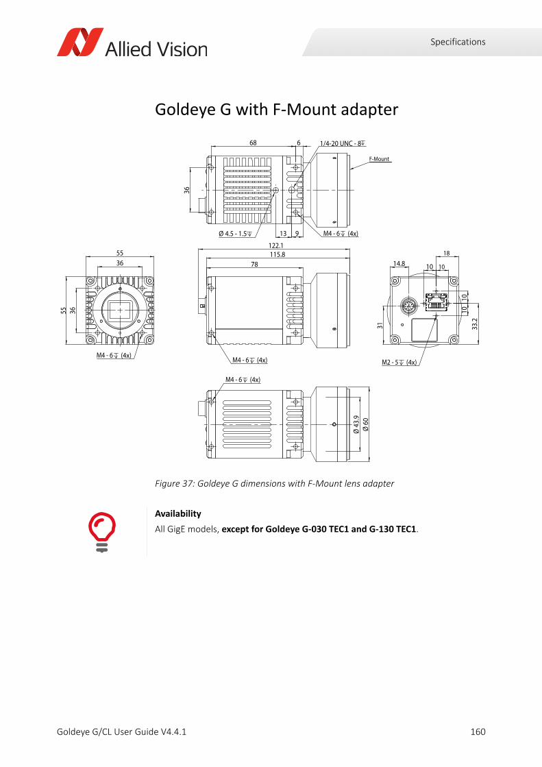
Specifications
Goldeye G with F-Mount adapter
Figure 37: Goldeye G dimensions with F-Mount lens adapter
Availability
All GigE models, except for Goldeye G-030 TEC1 and G-130 TEC1.
78115.8122.1
M4 - 6 (4x)
14.8
1010
33.2
31
18
10 10
M2 - 5 (4x)
36
68 6
9
1/4-20 UNC - 8
M4 - 6 (4x)13Ø 4.5 - 1.5
F-Mount
M4 - 6 (4x)
Ø60
Ø43
.9M4 - 6 (4x)
5536
55 36
160Goldeye G/CL User Guide V4.4.1
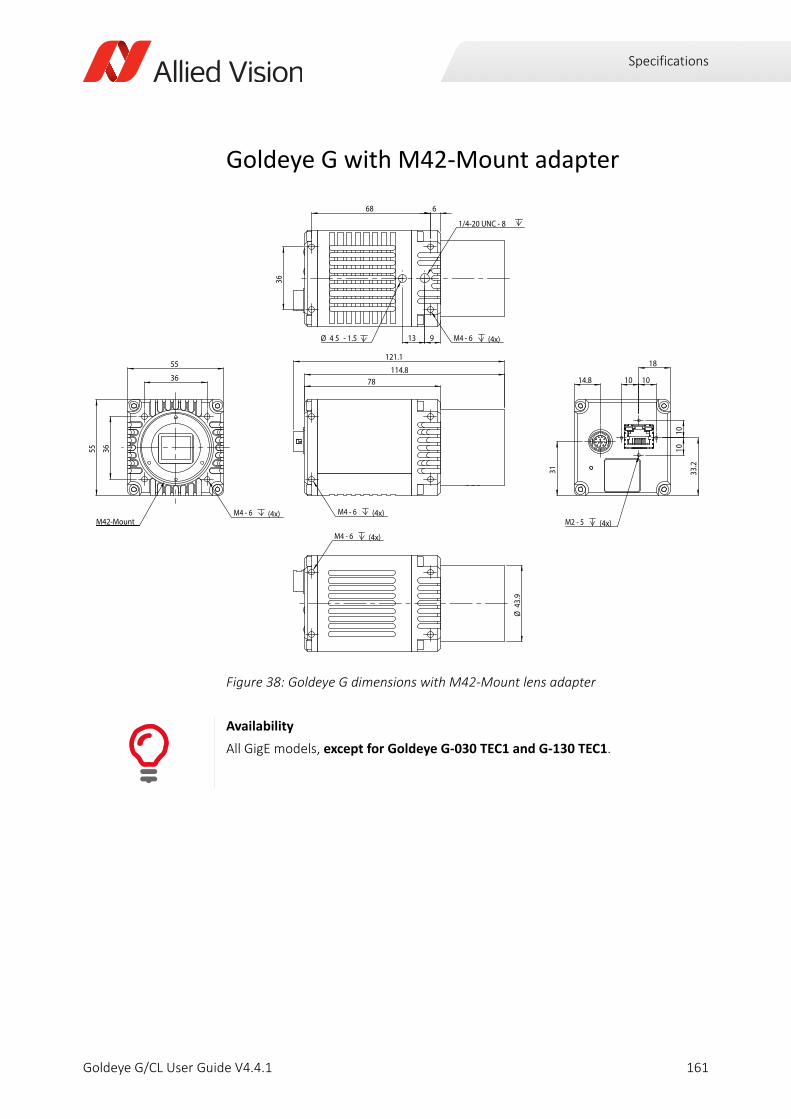
Specifications
Goldeye G with M42-Mount adapter
Figure 38: Goldeye G dimensions with M42-Mount lens adapter
Availability
All GigE models, except for Goldeye G-030 TEC1 and G-130 TEC1.
M4 - 6 (4x)
78114.8
121.1
M4 - 6 (4x)
36
36
55
55
M42-Mount M2 - 5 (4x)
14.8
18
10 10
33.2
1010
31
M4 - 6 (4x)
1/4-20 UNC - 8
913
668
36
Ø 4 5 - 1.5
M4 - 6 (4x)
Ø43
.9
161Goldeye G/CL User Guide V4.4.1
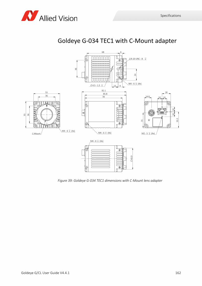
Specifications
Goldeye G-034 TEC1 with C-Mount adapter
Figure 39: Goldeye G-034 TEC1 dimensions with C-Mount lens adapter
78
92.1 85.8
M4 - 6 (4x)
55 36
36
55
C-MountM4 - 6 (4x)
10
10
33.
2
31
14.8 10 10
18
M2 - 5 (4x) 2
4
36
4.5 - 1.5 13 9
68 6
1/4-20 UNC - 8
M4 - 6 (4x)
43
.9
M4 - 6 (4x)
162Goldeye G/CL User Guide V4.4.1
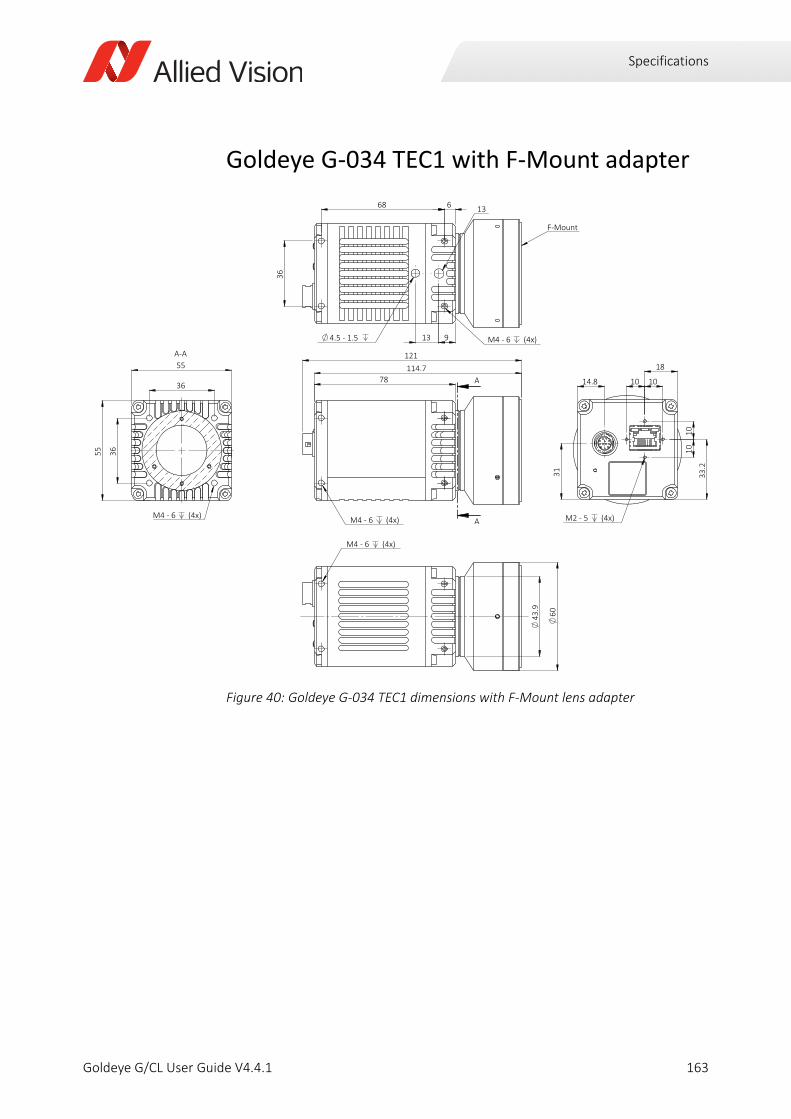
Specifications
Goldeye G-034 TEC1 with F-Mount adapter
Figure 40: Goldeye G-034 TEC1 dimensions with F-Mount lens adapter
78
M4 - 6 (4x)
121 114.7
A
A
14.8
31
M2 - 5 (4x)
10
10
33.
2
18
10 10
6
4.5 - 1.5
36
68
13 9
F-Mount
13
M4 - 6 (4x)
M4 - 6 (4x)
43.9
60
36
55
55
36
A-A
M4 - 6 (4x)
163Goldeye G/CL User Guide V4.4.1
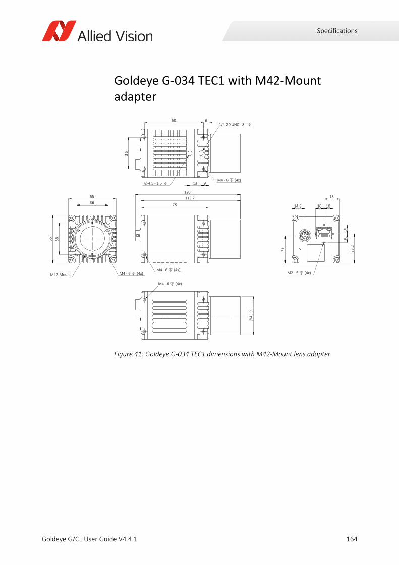
Specifications
Goldeye G-034 TEC1 with M42-Mount adapter
Figure 41: Goldeye G-034 TEC1 dimensions with M42-Mount lens adapter
120 113.7
78
M4 - 6 (4x)
55 36
36
55
M42-Mount M4 - 6 (4x)
31
14.8 10 10
10
10
33.
2
18
M2 - 5 (4x)
36
68 6
13 9 4.5 - 1.5
1/4-20 UNC - 8
M4 - 6 (4x)
43
.9
M4 - 6 (4x)
164Goldeye G/CL User Guide V4.4.1
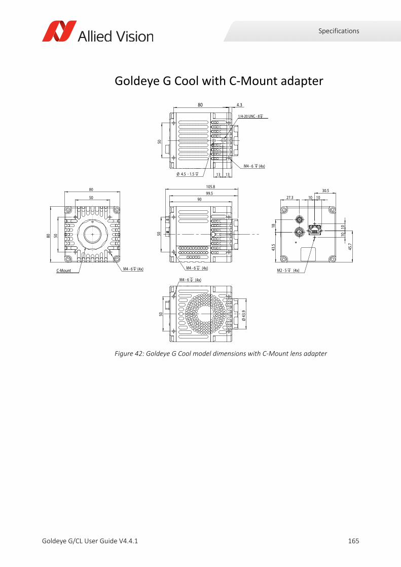
Specifications
Goldeye G Cool with C-Mount adapter
Figure 42: Goldeye G Cool model dimensions with C-Mount lens adapter
90
M4 - 6 (4x)
50
99.5105.8
80 4.3
1313
M4 - 6 (4x)
Ø 4.5 - 1.5
50
1/4-20 UNC - 8
80
80
50
50
M4 - 6 (4x)C-Mount
27.3
43.5
18
30.5
45.7
1010
10 10
M2 - 5 (4x)
M4 - 6 (4x)
50
Ø43
.9
165Goldeye G/CL User Guide V4.4.1
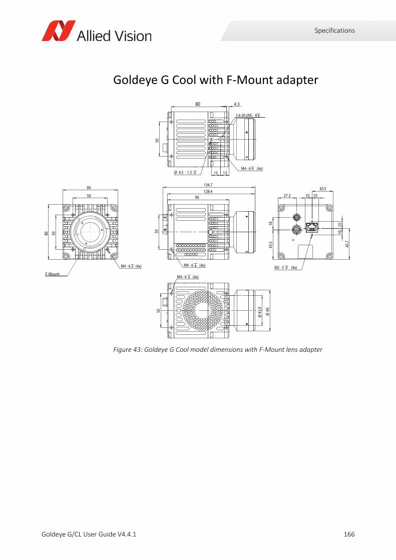
Specifications
Goldeye G Cool with F-Mount adapter
Figure 43: Goldeye G Cool model dimensions with F-Mount lens adapter
90
M4 - 6 (4x)
50
128.4134.7
80 4.3
1313M4 - 6 (4x)
Ø 4.5 - 1.5
50
1/4-20 UNC - 8
80
80
50
50
M4 - 6 (4x)
F-Mount
27.3
43.5
18
30.5
45.7
1010
10 10
M2 - 5 (4x)
M4 - 6 (4x)
50
Ø43
,9
Ø60
166Goldeye G/CL User Guide V4.4.1

Specifications
Goldeye G Cool with M42-Mount adapter
Figure 44: Goldeye G Cool model dimensions with M42-Mount lens adapter
90
M4 - 6 (4x)
50
127.4133.7
80 4.3
1313
M4 - 6 (4x)
Ø 4.5 - 1.5
50
1/4-20 UNC - 8
80
80
50
50
M4 - 6 (4x)M42-Mount
27.3
43.5
18
30.5
45.7
1010
10 10
M2 - 5 (4x)
M4 - 6 (4x)
50
Ø43
,9
167Goldeye G/CL User Guide V4.4.1
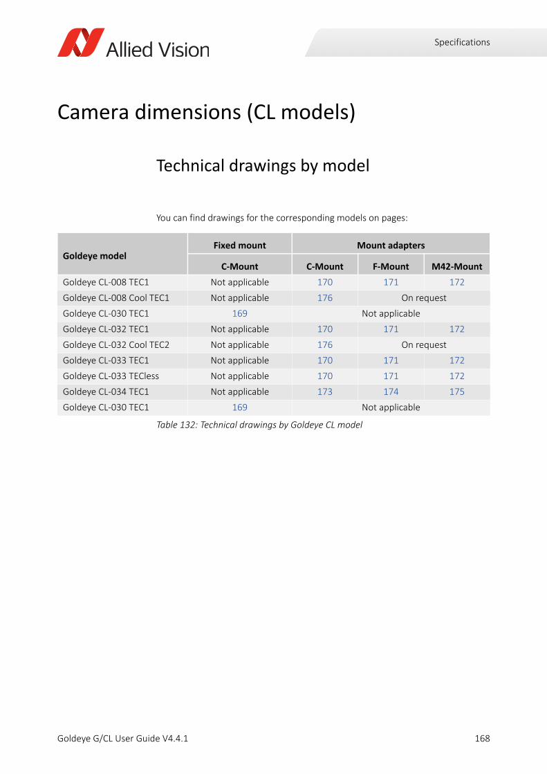
Specifications
Camera dimensions (CL models)
Technical drawings by model
You can find drawings for the corresponding models on pages:
Goldeye modelFixed mount Mount adapters
C-Mount C-Mount F-Mount M42-Mount
Goldeye CL-008 TEC1 Not applicable 170 171 172
Goldeye CL-008 Cool TEC1 Not applicable 176 On request
Goldeye CL-030 TEC1 169 Not applicable
Goldeye CL-032 TEC1 Not applicable 170 171 172
Goldeye CL-032 Cool TEC2 Not applicable 176 On request
Goldeye CL-033 TEC1 Not applicable 170 171 172
Goldeye CL-033 TECless Not applicable 170 171 172
Goldeye CL-034 TEC1 Not applicable 173 174 175
Goldeye CL-030 TEC1 169 Not applicable
Table 132: Technical drawings by Goldeye CL model
168Goldeye G/CL User Guide V4.4.1
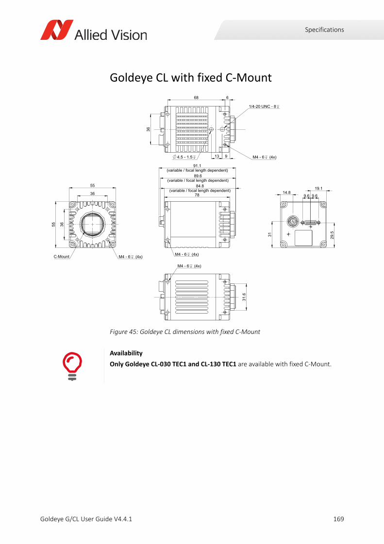
Specifications
Goldeye CL with fixed C-Mount
Figure 45: Goldeye CL dimensions with fixed C-Mount
Availability
Only Goldeye CL-030 TEC1 and CL-130 TEC1 are available with fixed C-Mount.
169Goldeye G/CL User Guide V4.4.1
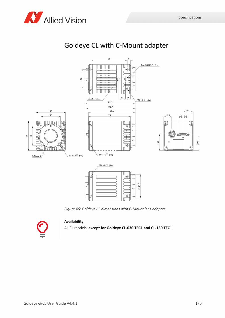
Specifications
Goldeye CL with C-Mount adapter
Figure 46: Goldeye CL dimensions with C-Mount lens adapter
Availability
All CL models, except for Goldeye CL-030 TEC1 and CL-130 TEC1.
93.2
91.7
78
86.9
M4 - 6 (4x) 3
1
14.8
19.1
29.
5
9.6 9.6
M4 - 6 (4x)
36
36
55
55
C-Mount
M4 - 6 (4x)
1/4-20 UNC - 8
4.5 - 1.5
68 6
36
13 9
M4 - 6 (4x)
43
.9
170Goldeye G/CL User Guide V4.4.1
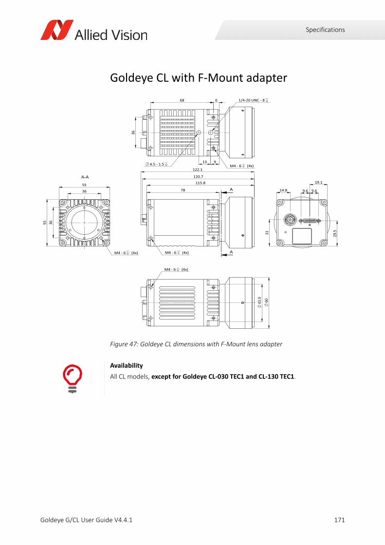
Specifications
Goldeye CL with F-Mount adapter
Figure 47: Goldeye CL dimensions with F-Mount lens adapter
Availability
All CL models, except for Goldeye CL-030 TEC1 and CL-130 TEC1.
122.1
120.7
78
115.8
M4 - 6 (4x)
31
14.8
19.1
29.
5
9.6 9.6
M4 - 6 (4x)
1/4-20 UNC - 8
4.5 - 1.5
68 6
36
13 9
M4 - 6 (4x)
60
43
.9
36
36
55
55
M4 - 6 (4x)
171Goldeye G/CL User Guide V4.4.1
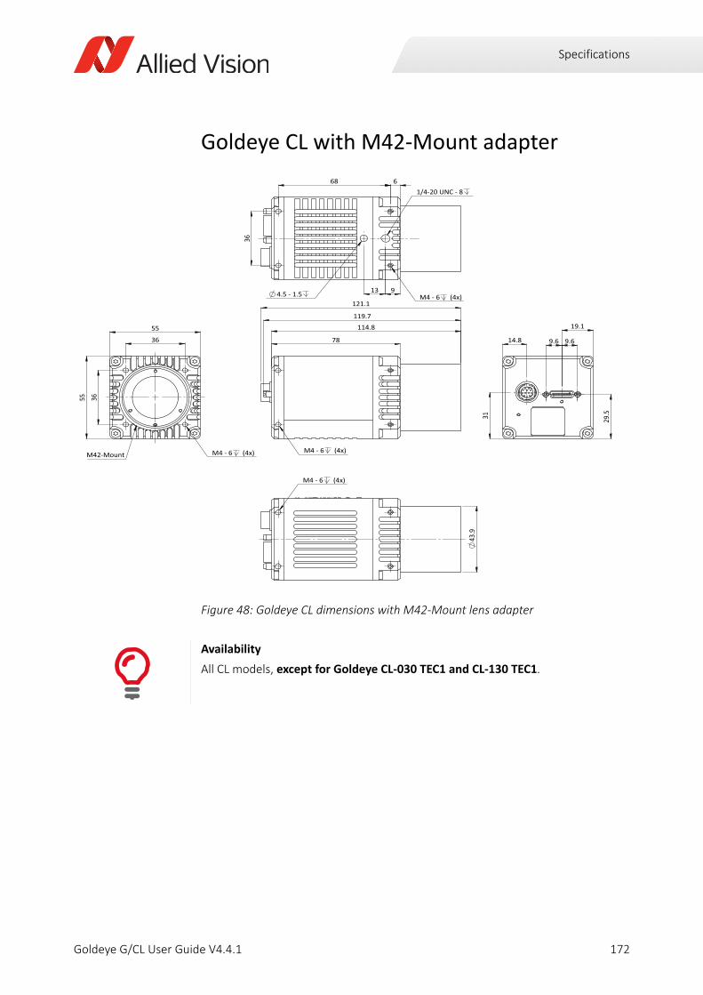
Specifications
Goldeye CL with M42-Mount adapter
Figure 48: Goldeye CL dimensions with M42-Mount lens adapter
Availability
All CL models, except for Goldeye CL-030 TEC1 and CL-130 TEC1.
121.1
119.7
78
114.8
M4 - 6 (4x)
31
14.8
19.1
29.
5
9.6 9.6
M4 - 6 (4x)
36
36
55
55
M42-Mount
M4 - 6 (4x)
1/4-20 UNC - 8
4.5 - 1.5
68 6
36
13 9
M4 - 6 (4x)
43.9
172Goldeye G/CL User Guide V4.4.1
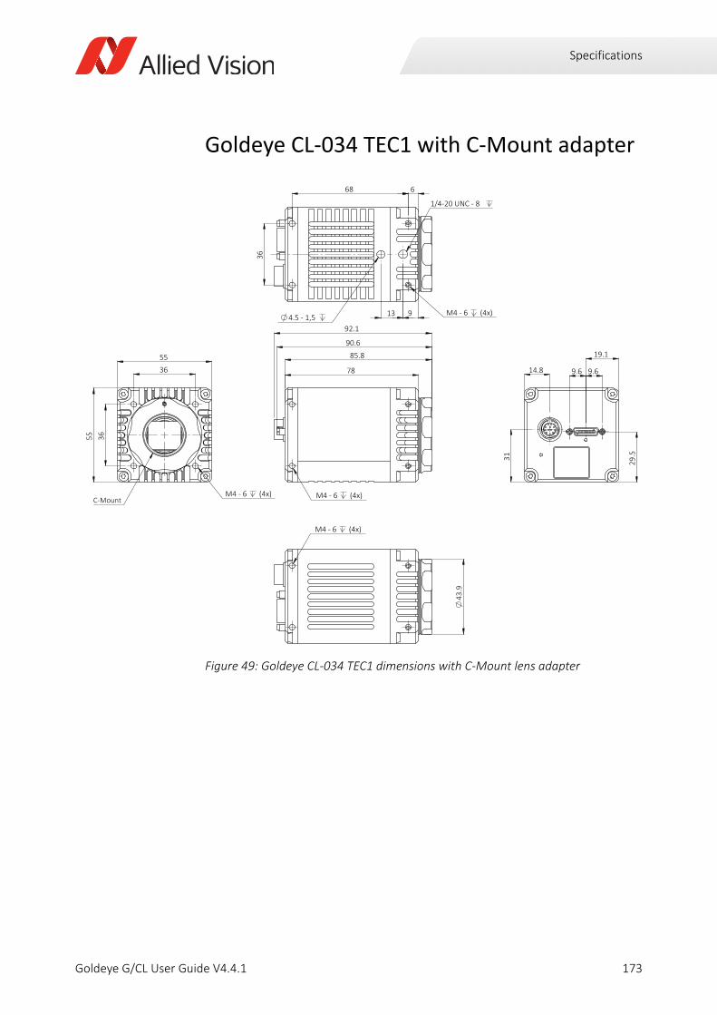
Specifications
Goldeye CL-034 TEC1 with C-Mount adapter
Figure 49: Goldeye CL-034 TEC1 dimensions with C-Mount lens adapter
92.1
90.6
85.8
M4 - 6 (4x)
78
31
14.8
19.1
29.
5
9.6 9.6
36
55
36 55
C-Mount M4 - 6 (4x)
4.5 - 1,5
36
68 6
13 9
1/4-20 UNC - 8
M4 - 6 (4x)
M4 - 6 (4x)
43
.9
173Goldeye G/CL User Guide V4.4.1
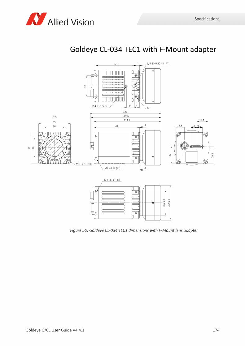
Specifications
Goldeye CL-034 TEC1 with F-Mount adapter
Figure 50: Goldeye CL-034 TEC1 dimensions with F-Mount lens adapter
78
M4 - 6 (4x)
121 119.6
114.7
A
A 3
1
14.8
19.1
29.
5
9.6 9.6
4.5 - 1,5
36
13 9
6 68
13
1/4-20 UNC - 8
M4 - 6 (4x)
43
.9
59
.8
55
55
36
36
A-A
M4 - 6 (4x)
174Goldeye G/CL User Guide V4.4.1
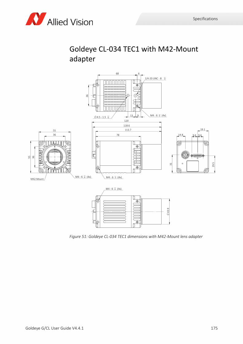
Specifications
Goldeye CL-034 TEC1 with M42-Mount adapter
Figure 51: Goldeye CL-034 TEC1 dimensions with M42-Mount lens adapter
120
118.6
113.7
M4 - 6 (4x)
78
31
14.8
19.1
29.
5
9.6 9.6
36
55
36 55
M42-Mount M4 - 6 (4x)
4.5 - 1.5
36
68 6
13 9
1/4-20 UNC - 8
M4 - 6 (4x)
M4 - 6 (4x)
43
.9
175Goldeye G/CL User Guide V4.4.1
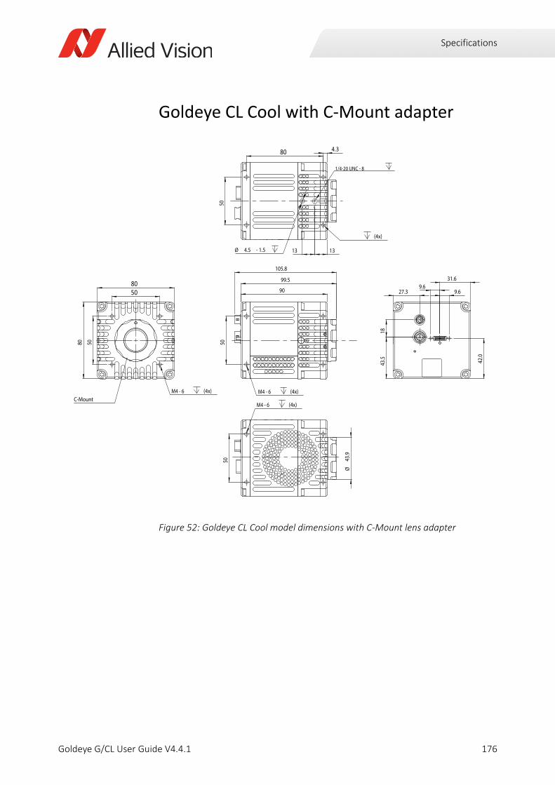
Specifications
Goldeye CL Cool with C-Mount adapter
Figure 52: Goldeye CL Cool model dimensions with C-Mount lens adapter
M4 - 6 (4x)
50
90
99.5
105.8
80
8050
50
M4 - 6 (4x) C-Mount
80 4.3
M4 - 6 (4x)
1/4-20 UNC - 8
50
1313Ø 4.5 - 1.5
27.3
1843
.5
9.69.6
42.0
31.6
Ø43
.9
50
M4 - 6 (4x)
176Goldeye G/CL User Guide V4.4.1
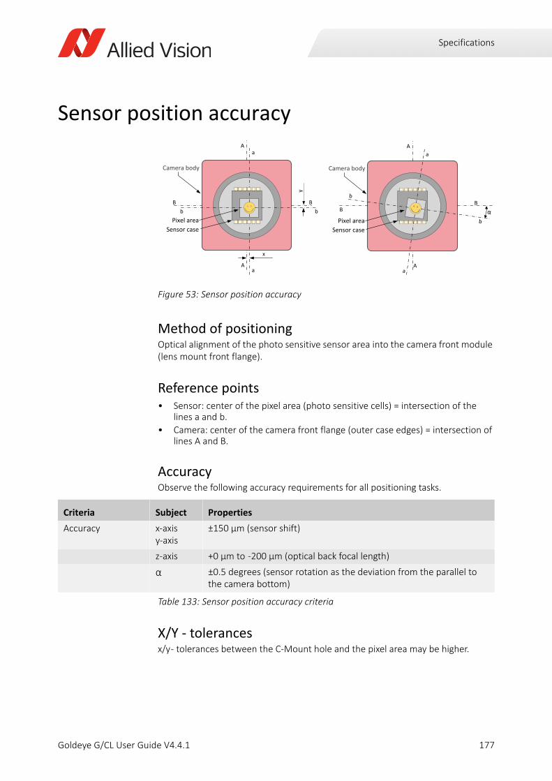
Specifications
Sensor position accuracy
Method of positioningOptical alignment of the photo sensitive sensor area into the camera front module (lens mount front flange).
Reference points• Sensor: center of the pixel area (photo sensitive cells) = intersection of the
lines a and b.
• Camera: center of the camera front flange (outer case edges) = intersection of lines A and B.
AccuracyObserve the following accuracy requirements for all positioning tasks.
X/Y - tolerancesx/y - tolerances between the C-Mount hole and the pixel area may be higher.
Figure 53: Sensor position accuracy
Criteria Subject Properties
Accuracy x-axisy-axis
±150 µm (sensor shift)
z-axis +0 µm to -200 µm (optical back focal length)
α ±0.5 degrees (sensor rotation as the deviation from the parallel to the camera bottom)
Table 133: Sensor position accuracy criteria
Camera body
bPixel area
Sensor case
B Bb
aA
Aa
x
y
Camera body
Pixel areaSensor case
BB
A
A
b
b
a
a
177Goldeye G/CL User Guide V4.4.1
Accessories
Goldeye G/CL User Guide V4.4.1
This chapter includes:
Electrical connections ......................................................... 179Power supplies .................................................................... 179Ethernet adapters ............................................................... 181Camera Link cables.............................................................. 181Hirose 12-pin I/O connectors and cables ........................... 182Lens mount adapters .......................................................... 183Lens mount adapters .......................................................... 183Optical filters and accessories ............................................ 184Heat sink set........................................................................ 186
178
Accessories
Electrical connectionsIn this section you find a selection of essential accessories to get your Goldeye camera up and running quickly.
These accessories are also listed in the appropriate places throughout this manual.
Allied Vision provides accessories to run and connect the Goldeye. To obtain an overview of all accessories available, go to the Allied Vision Accessories webpage.
Power supplies
Goldeye G/CL models Use only with the following Goldeye models:
• G/CL-008 TEC1
• G/CL-030 TEC1
• G/CL-032 TEC1
• G/CL-033 TEC1 and G/CL-033 TECless
• G/CL-034 TEC1
• G/CL-130 TEC1
Goldeye G/CL Cool modelsUse only with the following Goldeye Cool models:
• G/CL-008 Cool TEC1
• G/CL-032 Cool TEC2
Product code Description
13869Power supply 12V DC 24W 12-Pin Hirose Desktop Power Supply 100-240V AC -> 12V 2A DC Hirose 12p without AC power cord
Table 134: Power supply for Goldeye standard models
Product code Description
13867Power supply 12V DC 24W 4-Pin Hirose Desktop Power Supply 100-240V AC -> 12V 2A DC Hirose 4-pin without AC power cord
Table 135: Power supply for Goldeye Cool models
179Goldeye G/CL User Guide V4.4.1

Accessories
AC supply cables for power supplies
Hirose 4-pin power cables for Goldeye Cool models
Product code Description
13865
AC power cable Length: 1.8 metersEU <-> C13 CEE 7/7 W90 <-> IEC320-C13 for use with IEC320-C14 socket, for power supply 13867 and 13869
13866
AC power cable Length: 1.8 metersUS <-> C13 NEMA 5-15P straight <-> IEC320-C13 for use with IEC320-C14 socket, for power supply 13867 and 13869
Table 136: AC supply cables for power supplies
Product code Description
1068904Power cable with Hirose 4-pin female connector to open endLength: 2.0 meters
1068905Power cable with Hirose 4-pin female connector to open endLength: 3.0 meters
1068906Power cable with Hirose 4-pin female connector to open endLength: 5.0 meters
1068907Power cable with Hirose 4-pin female connector to open endLength: 10.0 meters
Table 137: Hirose 4-pin power cables for Goldeye Cool models
180Goldeye G/CL User Guide V4.4.1
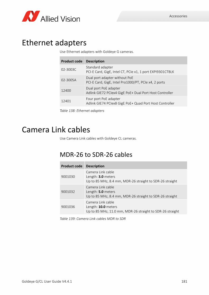
Accessories
Ethernet adaptersUse Ethernet adapters with Goldeye G cameras.
Camera Link cablesUse Camera Link cables with Goldeye CL cameras.
MDR-26 to SDR-26 cables
Product code Description
02-3003CStandard adapterPCI-E Card, GigE, Intel CT, PCIe x1, 1 port EXPI9301CTBLK
02-3005ADual port adapter without PoEPCI-E Card, GigE, Intel Pro1000/PT, PCIe x4, 2 ports
12400Dual port PoE adapterAdlink GIE72 PCIex4 GigE PoE+ Dual Port Host Controller
12401Four port PoE adapterAdlink GIE74 PCIex8 GigE PoE+ Quad Port Host Controller
Table 138: Ethernet adapters
Product code Description
9001030Camera Link cableLength: 3.0 metersUp to 85 MHz, 8.4 mm, MDR-26 straight to SDR-26 straight
9001032Camera Link cableLength: 5.0 metersUp to 85 MHz, 8.4 mm, MDR-26 straight to SDR-26 straight
9001036Camera Link cableLength: 10.0 metersUp to 85 MHz, 11.0 mm, MDR-26 straight to SDR-26 straight
Table 139: Camera Link cables MDR to SDR
181Goldeye G/CL User Guide V4.4.1
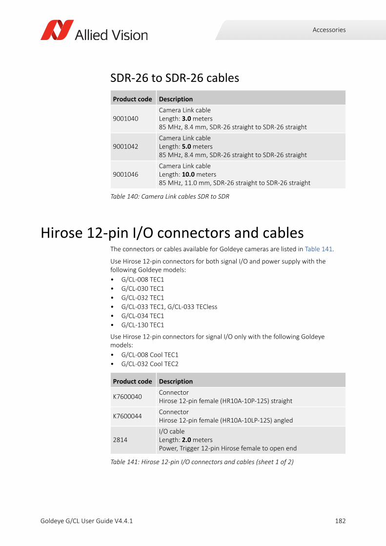
Accessories
SDR-26 to SDR-26 cables
Hirose 12-pin I/O connectors and cablesThe connectors or cables available for Goldeye cameras are listed in Table 141.
Use Hirose 12-pin connectors for both signal I/O and power supply with the following Goldeye models:
• G/CL-008 TEC1
• G/CL-030 TEC1
• G/CL-032 TEC1
• G/CL-033 TEC1, G/CL-033 TECless
• G/CL-034 TEC1
• G/CL-130 TEC1
Use Hirose 12-pin connectors for signal I/O only with the following Goldeye models:
• G/CL-008 Cool TEC1
• G/CL-032 Cool TEC2
Product code Description
9001040Camera Link cableLength: 3.0 meters85 MHz, 8.4 mm, SDR-26 straight to SDR-26 straight
9001042Camera Link cableLength: 5.0 meters85 MHz, 8.4 mm, SDR-26 straight to SDR-26 straight
9001046Camera Link cableLength: 10.0 meters85 MHz, 11.0 mm, SDR-26 straight to SDR-26 straight
Table 140: Camera Link cables SDR to SDR
Product code Description
K7600040ConnectorHirose 12-pin female (HR10A-10P-12S) straight
K7600044ConnectorHirose 12-pin female (HR10A-10LP-12S) angled
2814I/O cableLength: 2.0 metersPower, Trigger 12-pin Hirose female to open end
Table 141: Hirose 12-pin I/O connectors and cables (sheet 1 of 2)
182Goldeye G/CL User Guide V4.4.1
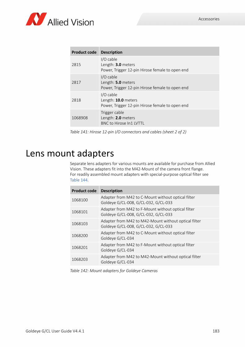
Accessories
Lens mount adaptersSeparate lens adapters for various mounts are available for purchase from Allied Vision. These adapters fit into the M42-Mount of the camera front flange. For readily assembled mount adapters with special-purpose optical filter see Table 144.
2815I/O cableLength: 3.0 metersPower, Trigger 12-pin Hirose female to open end
2817I/O cableLength: 5.0 metersPower, Trigger 12-pin Hirose female to open end
2818I/O cableLength: 10.0 metersPower, Trigger 12-pin Hirose female to open end
1068908Trigger cableLength: 2.0 metersBNC to Hirose In1 LVTTL
Product code Description
1068100Adapter from M42 to C-Mount without optical filter Goldeye G/CL-008, G/CL-032, G/CL-033
1068101Adapter from M42 to F-Mount without optical filter Goldeye G/CL-008, G/CL-032, G/CL-033
1068103Adapter from M42 to M42-Mount without optical filter Goldeye G/CL-008, G/CL-032, G/CL-033
1068200Adapter from M42 to C-Mount without optical filter Goldeye G/CL-034
1068201Adapter from M42 to F-Mount without optical filter Goldeye G/CL-034
1068203Adapter from M42 to M42-Mount without optical filter Goldeye G/CL-034
Table 142: Mount adapters for Goldeye Cameras
Product code Description
Table 141: Hirose 12-pin I/O connectors and cables (sheet 2 of 2)
183Goldeye G/CL User Guide V4.4.1
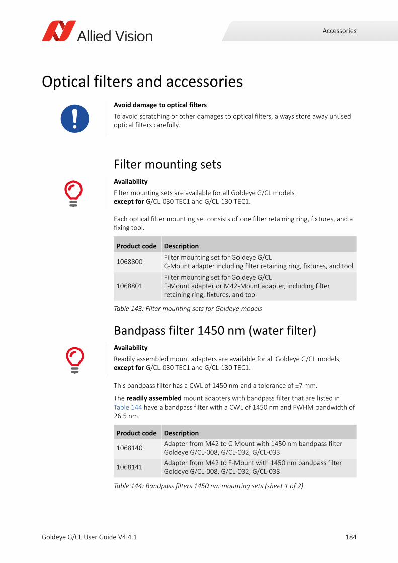
Accessories
Optical filters and accessories
Filter mounting sets
Each optical filter mounting set consists of one filter retaining ring, fixtures, and a fixing tool.
Bandpass filter 1450 nm (water filter)
This bandpass filter has a CWL of 1450 nm and a tolerance of ±7 mm.
The readily assembled mount adapters with bandpass filter that are listed in Table 144 have a bandpass filter with a CWL of 1450 nm and FWHM bandwidth of 26.5 nm.
Avoid damage to optical filters
To avoid scratching or other damages to optical filters, always store away unused optical filters carefully.
Availability
Filter mounting sets are available for all Goldeye G/CL models except for G/CL-030 TEC1 and G/CL-130 TEC1.
Product code Description
1068800Filter mounting set for Goldeye G/CLC-Mount adapter including filter retaining ring, fixtures, and tool
1068801Filter mounting set for Goldeye G/CL F-Mount adapter or M42-Mount adapter, including filter retaining ring, fixtures, and tool
Table 143: Filter mounting sets for Goldeye models
Availability
Readily assembled mount adapters are available for all Goldeye G/CL models, except for G/CL-030 TEC1 and G/CL-130 TEC1.
Product code Description
1068140Adapter from M42 to C-Mount with 1450 nm bandpass filterGoldeye G/CL-008, G/CL-032, G/CL-033
1068141Adapter from M42 to F-Mount with 1450 nm bandpass filterGoldeye G/CL-008, G/CL-032, G/CL-033
Table 144: Bandpass filters 1450 nm mounting sets (sheet 1 of 2)
184Goldeye G/CL User Guide V4.4.1
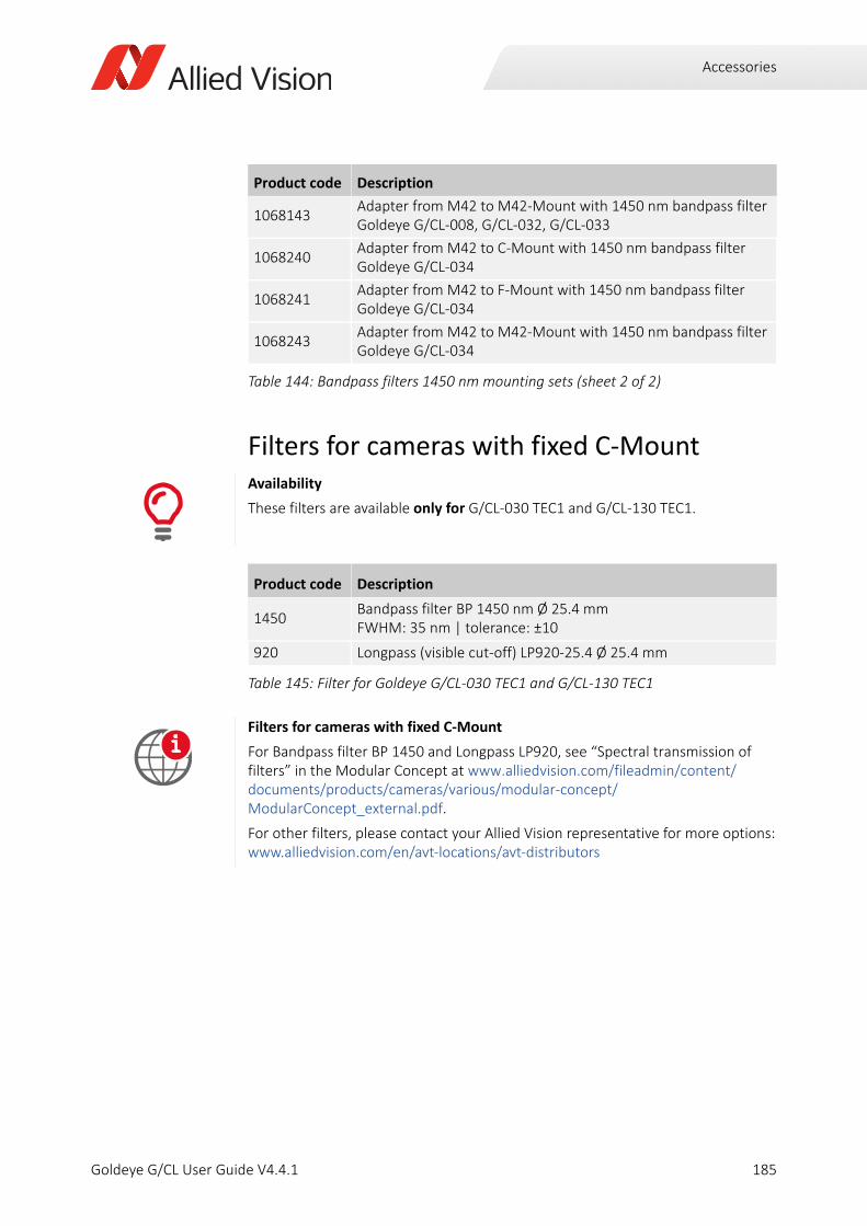
Accessories
Filters for cameras with fixed C-Mount
1068143Adapter from M42 to M42-Mount with 1450 nm bandpass filterGoldeye G/CL-008, G/CL-032, G/CL-033
1068240Adapter from M42 to C-Mount with 1450 nm bandpass filterGoldeye G/CL-034
1068241Adapter from M42 to F-Mount with 1450 nm bandpass filter Goldeye G/CL-034
1068243Adapter from M42 to M42-Mount with 1450 nm bandpass filter Goldeye G/CL-034
Availability
These filters are available only for G/CL-030 TEC1 and G/CL-130 TEC1.
Product code Description
1450Bandpass filter BP 1450 nm Ø 25.4 mmFWHM: 35 nm | tolerance: ±10
920 Longpass (visible cut-off) LP920-25.4 Ø 25.4 mm
Table 145: Filter for Goldeye G/CL-030 TEC1 and G/CL-130 TEC1
Filters for cameras with fixed C-Mount
For Bandpass filter BP 1450 and Longpass LP920, see “Spectral transmission of filters” in the Modular Concept at www.alliedvision.com/fileadmin/content/documents/products/cameras/various/modular-concept/ModularConcept_external.pdf.
For other filters, please contact your Allied Vision representative for more options:www.alliedvision.com/en/avt-locations/avt-distributors
Product code Description
Table 144: Bandpass filters 1450 nm mounting sets (sheet 2 of 2)
i
185Goldeye G/CL User Guide V4.4.1
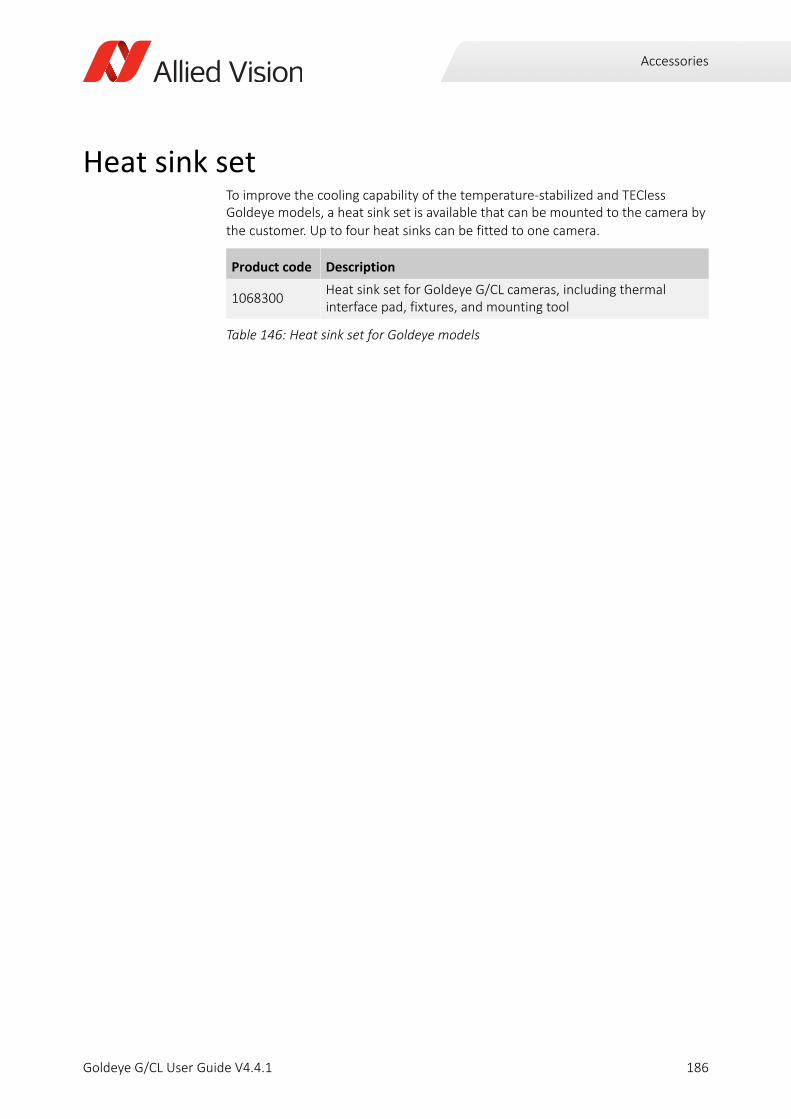
Accessories
Heat sink set To improve the cooling capability of the temperature-stabilized and TECless Goldeye models, a heat sink set is available that can be mounted to the camera by the customer. Up to four heat sinks can be fitted to one camera.
Product code Description
1068300Heat sink set for Goldeye G/CL cameras, including thermal interface pad, fixtures, and mounting tool
Table 146: Heat sink set for Goldeye models
186Goldeye G/CL User Guide V4.4.1
Using lens mounts and filters
Goldeye G/CL User Guide V4.4.1
This chapter includes:
Camera models and lens mounts ....................................... 188Changing the lens adapter.................................................. 188C-Mount lens adapter ......................................................... 189F-Mount lens adapter ......................................................... 192M42-Mount lens adapter ................................................... 194Adjusting the C-Mount........................................................ 197Replacing filters on cameras with fixed C-Mount............... 198Filter specifications ............................................................. 200
187
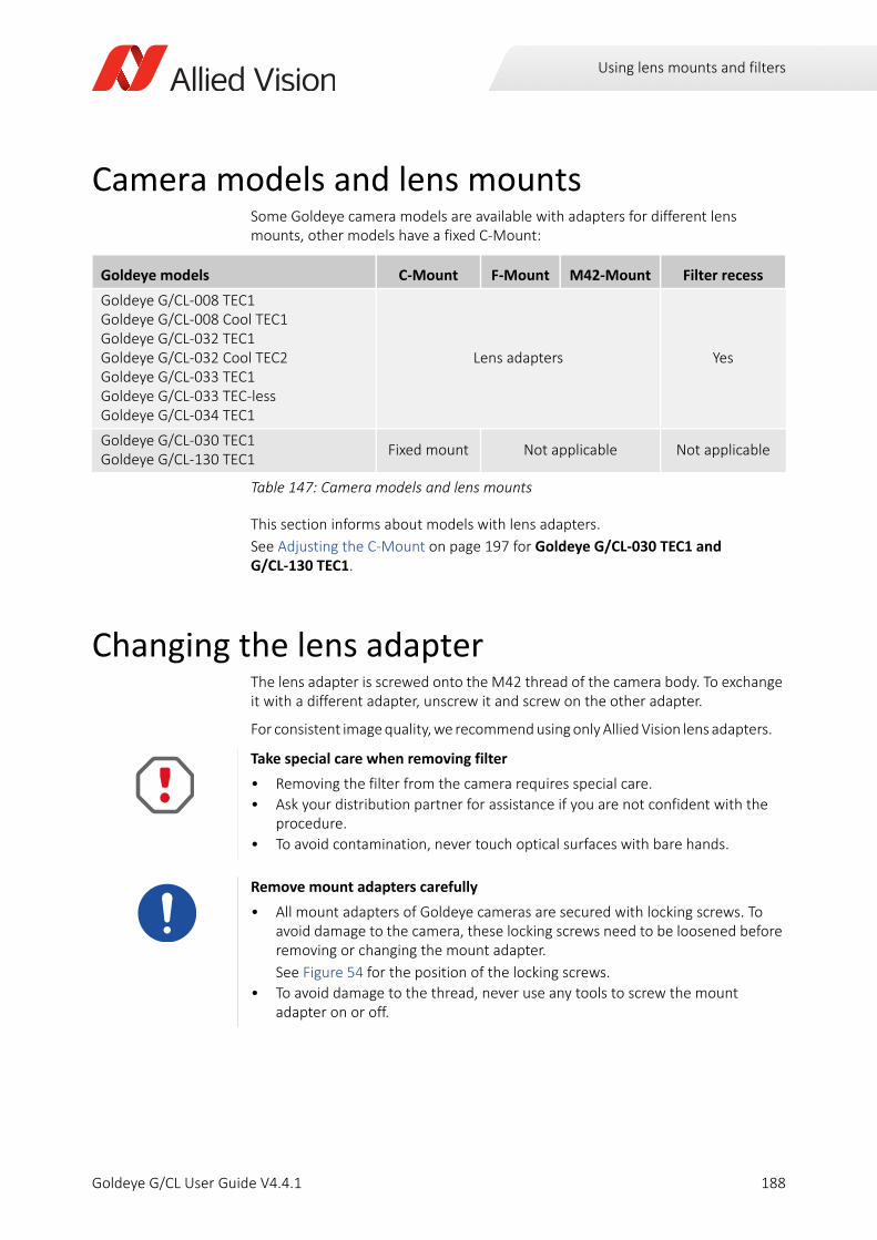
Using lens mounts and filters
Camera models and lens mountsSome Goldeye camera models are available with adapters for different lens mounts, other models have a fixed C-Mount:
This section informs about models with lens adapters.
See Adjusting the C-Mount on page 197 for Goldeye G/CL-030 TEC1 and G/CL-130 TEC1.
Changing the lens adapterThe lens adapter is screwed onto the M42 thread of the camera body. To exchange it with a different adapter, unscrew it and screw on the other adapter.
For consistent image quality, we recommend using only Allied Vision lens adapters.
Goldeye models C-Mount F-Mount M42-Mount Filter recess
Goldeye G/CL-008 TEC1Goldeye G/CL-008 Cool TEC1Goldeye G/CL-032 TEC1Goldeye G/CL-032 Cool TEC2 Goldeye G/CL-033 TEC1Goldeye G/CL-033 TEC-lessGoldeye G/CL-034 TEC1
Lens adapters Yes
Goldeye G/CL-030 TEC1Goldeye G/CL-130 TEC1
Fixed mount Not applicable Not applicable
Table 147: Camera models and lens mounts
Take special care when removing filter
• Removing the filter from the camera requires special care.
• Ask your distribution partner for assistance if you are not confident with the procedure.
• To avoid contamination, never touch optical surfaces with bare hands.
Remove mount adapters carefully
• All mount adapters of Goldeye cameras are secured with locking screws. To avoid damage to the camera, these locking screws need to be loosened before removing or changing the mount adapter.
See Figure 54 for the position of the locking screws.
• To avoid damage to the thread, never use any tools to screw the mount adapter on or off.
188Goldeye G/CL User Guide V4.4.1
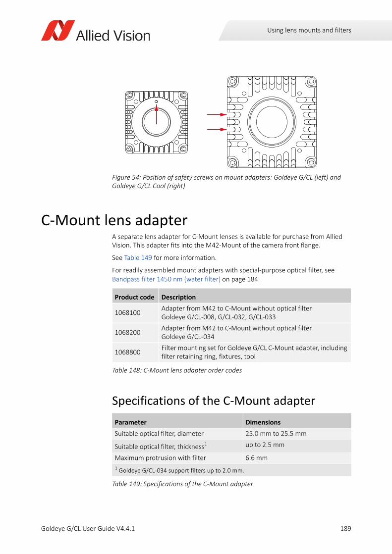
Using lens mounts and filters
C-Mount lens adapterA separate lens adapter for C-Mount lenses is available for purchase from Allied Vision. This adapter fits into the M42-Mount of the camera front flange.
See Table 149 for more information.
For readily assembled mount adapters with special-purpose optical filter, see Bandpass filter 1450 nm (water filter) on page 184.
Specifications of the C-Mount adapter
Figure 54: Position of safety screws on mount adapters: Goldeye G/CL (left) and Goldeye G/CL Cool (right)
Product code Description
1068100Adapter from M42 to C-Mount without optical filter Goldeye G/CL-008, G/CL-032, G/CL-033
1068200Adapter from M42 to C-Mount without optical filter Goldeye G/CL-034
1068800Filter mounting set for Goldeye G/CL C-Mount adapter, including filter retaining ring, fixtures, tool
Table 148: C-Mount lens adapter order codes
Parameter Dimensions
Suitable optical filter, diameter 25.0 mm to 25.5 mm
Suitable optical filter, thickness1 up to 2.5 mm
Maximum protrusion with filter 6.6 mm
1 Goldeye G/CL-034 support filters up to 2.0 mm.
Table 149: Specifications of the C-Mount adapter
189Goldeye G/CL User Guide V4.4.1
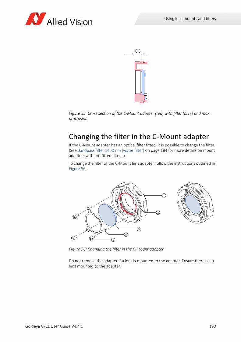
Using lens mounts and filters
Changing the filter in the C-Mount adapterIf the C-Mount adapter has an optical filter fitted, it is possible to change the filter. (See Bandpass filter 1450 nm (water filter) on page 184 for more details on mount adapters with pre-fitted filters.)
To change the filter of the C-Mount lens adapter, follow the instructions outlined in Figure 56.
Do not remove the adapter if a lens is mounted to the adapter. Ensure there is no lens mounted to the adapter.
Figure 55: Cross section of the C-Mount adapter (red) with filter (blue) and max. protrusion
Figure 56: Changing the filter in the C-Mount adapter
6.6
3
4
5
1
2
190Goldeye G/CL User Guide V4.4.1
Using lens mounts and filters
Removing the adapter from the cameraUnscrew the adapter (1) from the camera:
• Loosen the locking screw (2, shown from back of adapter) on the outside of the mount adapter. See Figure 54 on page 189 for the position of the locking screws.
• Use a 1.3 mm hex key for Goldeye models with Cool housing:
G/CL-008 Cool
G/CL-032 Cool.
• Use a 0.9 mm hex key for all other models.
• To avoid penetration of foreign substances into the camera, ensure that the front flange is covered with a dust cap. See Avoiding the necessity of camera cleaning on page 266.
Removing the filter from the mount adapterOn the back side of the mount, loosen the three cylinder bolts (5) of the filter fixing ring (4), using a Torx T6 tool.
1. Remove the fixing ring.
2. Remove the existing filter (3) from the adapter.
Installing a filter into the mount adapter1. Insert the new filter into the matching recess.
- See Figure 56 on page 190 (blue = filter, red = filter recess).
- See Table 149 on page 189 for dimensions of suitable filters.
2. Reinsert the fixing ring into the adapter.
3. Fix the ring with the three cylinder bolts. Note there are three sets of threads to suit filters of different thicknesses.
- Tighten the bolts with a maximum torque of 0.25 Nm.
Attaching the mount to Goldeye standard models1. Screw the adapter into the camera.
2. Tighten the locking screw with a maximum torque of 0.1 Nm.
Attaching the mount to Goldeye Cool modelsWhen used with Goldeye Cool models, the mount adapter is secured by two locking screws on the side of the camera. The thread in the mount adapter needs to be closed with a thread plug to avoid light incidence.
To apply the thread plug to a C-Mount adapter, follow the steps outlined in Figure 57.
1. Push the thread plug through the locking thread, from front to back, until the end lines up with the adapters front plane.
191Goldeye G/CL User Guide V4.4.1
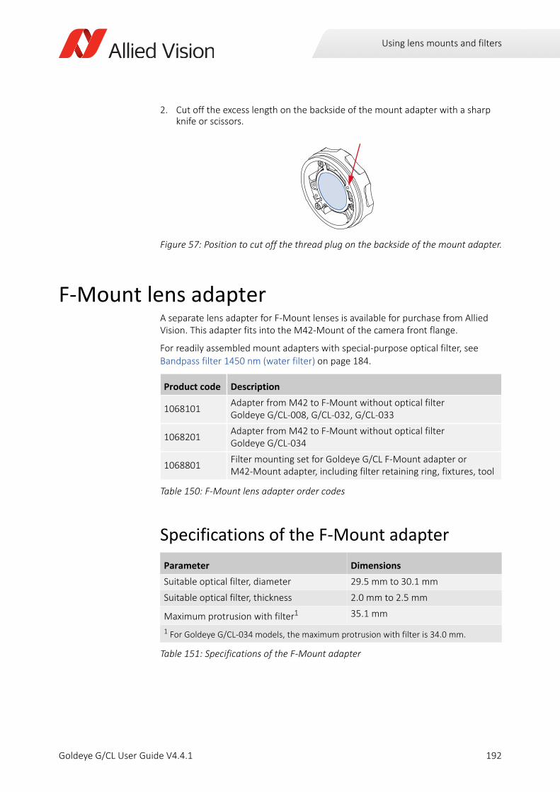
Using lens mounts and filters
2. Cut off the excess length on the backside of the mount adapter with a sharp knife or scissors.
F-Mount lens adapterA separate lens adapter for F-Mount lenses is available for purchase from Allied Vision. This adapter fits into the M42-Mount of the camera front flange.
For readily assembled mount adapters with special-purpose optical filter, see Bandpass filter 1450 nm (water filter) on page 184.
Specifications of the F-Mount adapter
Figure 57: Position to cut off the thread plug on the backside of the mount adapter.
Product code Description
1068101Adapter from M42 to F-Mount without optical filter Goldeye G/CL-008, G/CL-032, G/CL-033
1068201Adapter from M42 to F-Mount without optical filter Goldeye G/CL-034
1068801Filter mounting set for Goldeye G/CL F-Mount adapter or M42-Mount adapter, including filter retaining ring, fixtures, tool
Table 150: F-Mount lens adapter order codes
Parameter Dimensions
Suitable optical filter, diameter 29.5 mm to 30.1 mm
Suitable optical filter, thickness 2.0 mm to 2.5 mm
Maximum protrusion with filter1 35.1 mm
1 For Goldeye G/CL-034 models, the maximum protrusion with filter is 34.0 mm.
Table 151: Specifications of the F-Mount adapter
192Goldeye G/CL User Guide V4.4.1
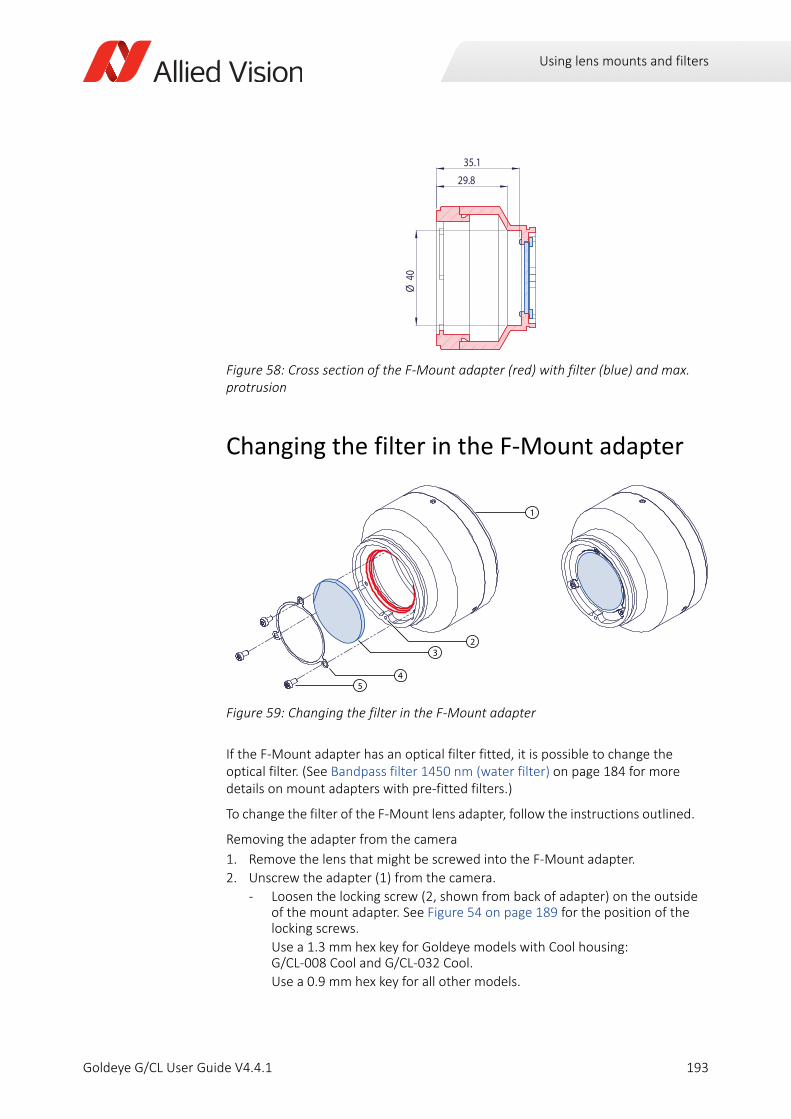
Using lens mounts and filters
Changing the filter in the F-Mount adapter
If the F-Mount adapter has an optical filter fitted, it is possible to change the optical filter. (See Bandpass filter 1450 nm (water filter) on page 184 for more details on mount adapters with pre-fitted filters.)
To change the filter of the F-Mount lens adapter, follow the instructions outlined.
Removing the adapter from the camera
1. Remove the lens that might be screwed into the F-Mount adapter.
2. Unscrew the adapter (1) from the camera.
- Loosen the locking screw (2, shown from back of adapter) on the outside of the mount adapter. See Figure 54 on page 189 for the position of the locking screws.
Use a 1.3 mm hex key for Goldeye models with Cool housing: G/CL-008 Cool and G/CL-032 Cool.
Use a 0.9 mm hex key for all other models.
Figure 58: Cross section of the F-Mount adapter (red) with filter (blue) and max. protrusion
Figure 59: Changing the filter in the F-Mount adapter
35.1
29.8
Ø40
1
23
45
193Goldeye G/CL User Guide V4.4.1
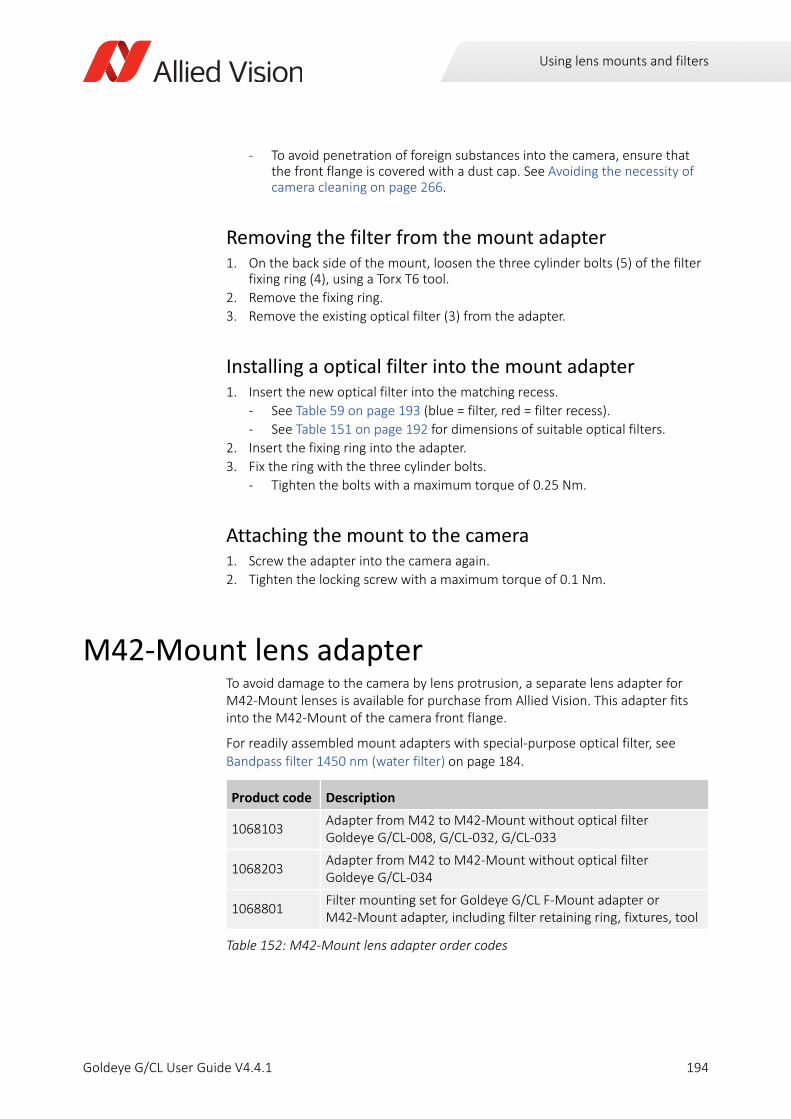
Using lens mounts and filters
- To avoid penetration of foreign substances into the camera, ensure that the front flange is covered with a dust cap. See Avoiding the necessity of camera cleaning on page 266.
Removing the filter from the mount adapter1. On the back side of the mount, loosen the three cylinder bolts (5) of the filter
fixing ring (4), using a Torx T6 tool.
2. Remove the fixing ring.
3. Remove the existing optical filter (3) from the adapter.
Installing a optical filter into the mount adapter1. Insert the new optical filter into the matching recess.
- See Table 59 on page 193 (blue = filter, red = filter recess).
- See Table 151 on page 192 for dimensions of suitable optical filters.
2. Insert the fixing ring into the adapter.
3. Fix the ring with the three cylinder bolts.
- Tighten the bolts with a maximum torque of 0.25 Nm.
Attaching the mount to the camera1. Screw the adapter into the camera again.
2. Tighten the locking screw with a maximum torque of 0.1 Nm.
M42-Mount lens adapterTo avoid damage to the camera by lens protrusion, a separate lens adapter for M42-Mount lenses is available for purchase from Allied Vision. This adapter fits into the M42-Mount of the camera front flange.
For readily assembled mount adapters with special-purpose optical filter, see Bandpass filter 1450 nm (water filter) on page 184.
Product code Description
1068103Adapter from M42 to M42-Mount without optical filter Goldeye G/CL-008, G/CL-032, G/CL-033
1068203Adapter from M42 to M42-Mount without optical filter Goldeye G/CL-034
1068801Filter mounting set for Goldeye G/CL F-Mount adapter or M42-Mount adapter, including filter retaining ring, fixtures, tool
Table 152: M42-Mount lens adapter order codes
194Goldeye G/CL User Guide V4.4.1
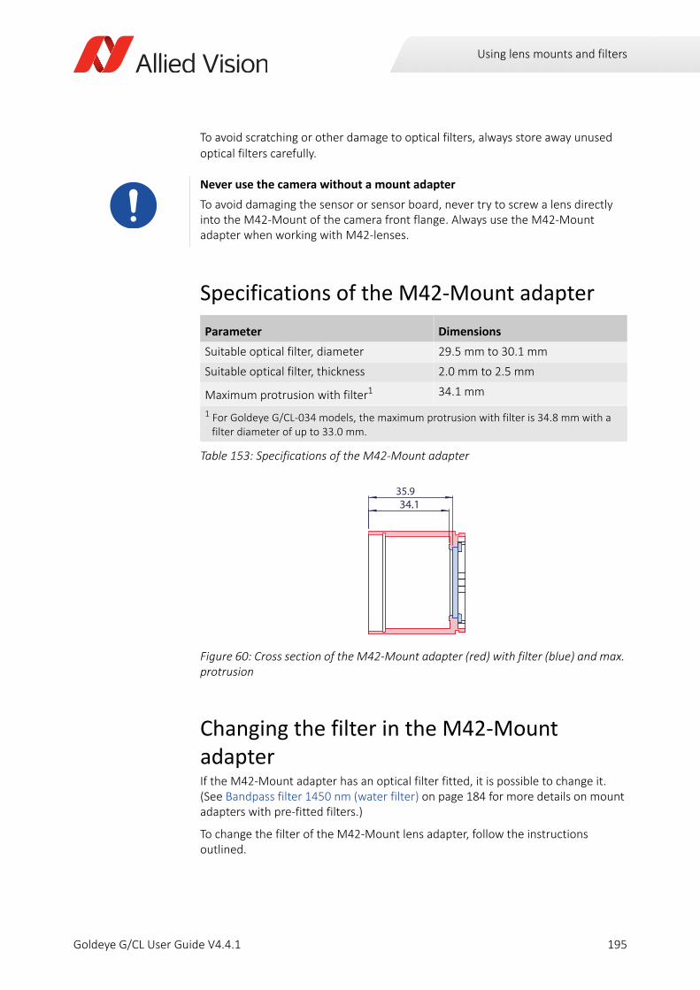
Using lens mounts and filters
To avoid scratching or other damage to optical filters, always store away unused optical filters carefully.
Specifications of the M42-Mount adapter
Changing the filter in the M42-Mount adapterIf the M42-Mount adapter has an optical filter fitted, it is possible to change it. (See Bandpass filter 1450 nm (water filter) on page 184 for more details on mount adapters with pre-fitted filters.)
To change the filter of the M42-Mount lens adapter, follow the instructions outlined.
Never use the camera without a mount adapter
To avoid damaging the sensor or sensor board, never try to screw a lens directly into the M42-Mount of the camera front flange. Always use the M42-Mount adapter when working with M42-lenses.
Parameter Dimensions
Suitable optical filter, diameter 29.5 mm to 30.1 mm
Suitable optical filter, thickness 2.0 mm to 2.5 mm
Maximum protrusion with filter1 34.1 mm
1 For Goldeye G/CL-034 models, the maximum protrusion with filter is 34.8 mm with a filter diameter of up to 33.0 mm.
Table 153: Specifications of the M42-Mount adapter
Figure 60: Cross section of the M42-Mount adapter (red) with filter (blue) and max. protrusion
35.934.1
195Goldeye G/CL User Guide V4.4.1
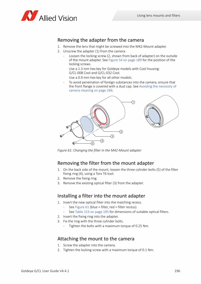
Using lens mounts and filters
Removing the adapter from the camera1. Remove the lens that might be screwed into the M42-Mount adapter.
2. Unscrew the adapter (1) from the camera.
- Loosen the locking screw (2, shown from back of adapter) on the outside of the mount adapter. See Figure 54 on page 189 for the position of the locking screws.
Use a 1.3 mm hex key for Goldeye models with Cool housing: G/CL-008 Cool and G/CL-032 Cool.
Use a 0.9 mm hex key for all other models.
- To avoid penetration of foreign substances into the camera, ensure that the front flange is covered with a dust cap. See Avoiding the necessity of camera cleaning on page 266.
Removing the filter from the mount adapter1. On the back side of the mount, loosen the three cylinder bolts (5) of the filter
fixing ring (4), using a Torx T6 tool.
2. Remove the fixing ring.
3. Remove the existing optical filter (3) from the adapter.
Installing a filter into the mount adapter1. Insert the new optical filter into the matching recess.
- See Figure 61 (blue = filter, red = filter recess).
- See Table 153 on page 195 for dimensions of suitable optical filters.
2. Insert the fixing ring into the adapter.
3. Fix the ring with the three cylinder bolts.
- Tighten the bolts with a maximum torque of 0.25 Nm.
Attaching the mount to the camera1. Screw the adapter into the camera.
2. Tighten the locking screw with a maximum torque of 0.1 Nm.
Figure 61: Changing the filter in the M42-Mount adapter
2
3
45
1
196Goldeye G/CL User Guide V4.4.1
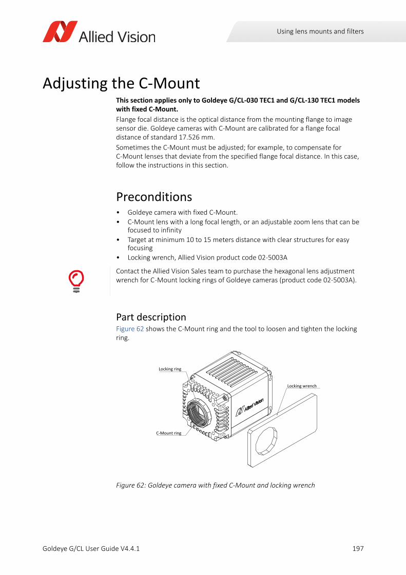
Using lens mounts and filters
Adjusting the C-MountThis section applies only to Goldeye G/CL-030 TEC1 and G/CL-130 TEC1 models with fixed C-Mount.
Flange focal distance is the optical distance from the mounting flange to image sensor die. Goldeye cameras with C-Mount are calibrated for a flange focal distance of standard 17.526 mm.
Sometimes the C-Mount must be adjusted; for example, to compensate for C-Mount lenses that deviate from the specified flange focal distance. In this case, follow the instructions in this section.
Preconditions• Goldeye camera with fixed C-Mount.
• C-Mount lens with a long focal length, or an adjustable zoom lens that can be focused to infinity
• Target at minimum 10 to 15 meters distance with clear structures for easy focusing
• Locking wrench, Allied Vision product code 02-5003A
Part description Figure 62 shows the C-Mount ring and the tool to loosen and tighten the locking ring.
Contact the Allied Vision Sales team to purchase the hexagonal lens adjustment wrench for C -Mount locking rings of Goldeye cameras (product code 02-5003A).
Figure 62: Goldeye camera with fixed C-Mount and locking wrench
Locking ring
Locking wrench
C-Mount ring
197Goldeye G/CL User Guide V4.4.1
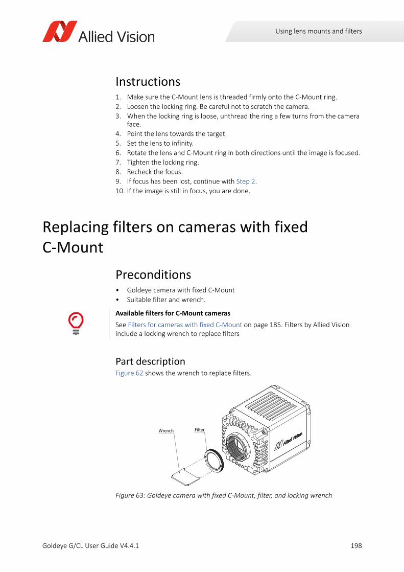
Using lens mounts and filters
Instructions1. Make sure the C-Mount lens is threaded firmly onto the C-Mount ring.
2. Loosen the locking ring. Be careful not to scratch the camera.
3. When the locking ring is loose, unthread the ring a few turns from the camera face.
4. Point the lens towards the target.
5. Set the lens to infinity.
6. Rotate the lens and C-Mount ring in both directions until the image is focused.
7. Tighten the locking ring.
8. Recheck the focus.
9. If focus has been lost, continue with Step 2.
10. If the image is still in focus, you are done.
Replacing filters on cameras with fixed C-Mount
Preconditions• Goldeye camera with fixed C-Mount
• Suitable filter and wrench.
Part description Figure 62 shows the wrench to replace filters.
Available filters for C-Mount cameras
See Filters for cameras with fixed C-Mount on page 185. Filters by Allied Vision include a locking wrench to replace filters
Figure 63: Goldeye camera with fixed C-Mount, filter, and locking wrench
Wrench Filter
198Goldeye G/CL User Guide V4.4.1
Using lens mounts and filters
Inserting filters
1. Remove the lens or protection cap from the C-Mount.
2. Place the filter on the wrench, with the pins of the wrench fitting into the holes of the filter ring.
3. Holding the filter with the wrench, engage the filter to the C-Mount.
4. Screw the filter clockwise into the C-Mount until you feel resistance.
5. Place a lens or protection cap on the C-Mount to keep dust away.
Removing filters1. Remove the lens or protection cap from the C-Mount.
2. Insert the pins of the wrench into the holes of the filter ring.
3. Screw the filter counter clockwise out of the C-Mount.
4. Place a lens or protection cap on the C-Mount to keep dust away.
5. Store the filter protected from dust.
Keep dust away
We recommend you to hold the camera with the lens mount facing the ground to keep dirt out.
199Goldeye G/CL User Guide V4.4.1
Using lens mounts and filters
Filter specifications
General terms explainedIn general, these types of filters are used to filter visible and invisible wavelengths of various frequencies:
• Bandpass filters are translucent for a certain wavelength, rejecting all wavelengths above and below the defined range.
• Longpass filters are translucent from a certain wavelength onwards and for all wavelengths above it, thus rejecting all wavelengths below.
• Visible cut-off filters are a subset of longpass filters that prevent visible light from passing to the sensor.
• Shortpass filters are translucent up to a certain wavelength and for all wavelengths below, thereby rejecting all wavelengths above.
• Notch or band reject filters are translucent for all wavelengths above and below a defined range, thereby rejecting all wavelengths of that range. A Band Reject filter can be seen as the opposite of a Bandpass filter.
Bandpass filtersThe Goldeye responds to wavelengths from about 900 nm to 1700 nm. Using a bandpass filter, it is possible to restrict the complete bandwidth to a certain range of wavelengths. That way, only a certain wavelength band is transmitted, all others are rejected.
The describing characteristics of a bandpass filter are properties like optical density, or spectral profile. The main characteristics, however, are the center wavelength (CWL) together with the bandwidth (full width at half maximum, FWHM) being transmitted. Bandpass filters can cut the transmitted frequencies more or less sharply. Accordingly, the increase or decrease in gain at the edges of the translucent frequency band is more or less steep. This results in certain properties for each bandpass filter, that are defined by the following terms.
Available filters
This chapter informs about different filters that can be used with Goldeye G/CL cameras.
For available filters, see Optical filters and accessories on page 184.
The Modular Concept lists a selection of standard options: www.alliedvision.com/fileadmin/content/documents/products/cameras/various/modular-concept/ModularConcept_external.pdf
Please contact your Allied Vision representative for more options:www.alliedvision.com/en/avt-locations/avt-distributors
i
200Goldeye G/CL User Guide V4.4.1
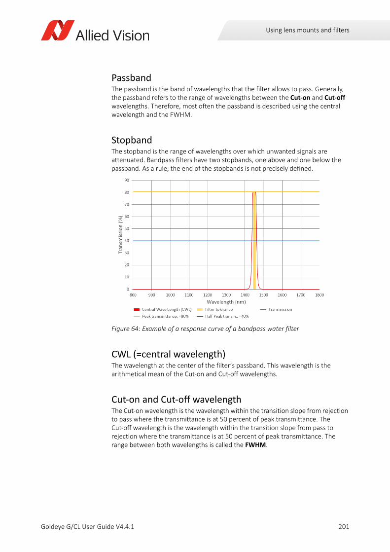
Using lens mounts and filters
PassbandThe passband is the band of wavelengths that the filter allows to pass. Generally, the passband refers to the range of wavelengths between the Cut-on and Cut-off wavelengths. Therefore, most often the passband is described using the central wavelength and the FWHM.
StopbandThe stopband is the range of wavelengths over which unwanted signals are attenuated. Bandpass filters have two stopbands, one above and one below the passband. As a rule, the end of the stopbands is not precisely defined.
CWL (=central wavelength)The wavelength at the center of the filter’s passband. This wavelength is the arithmetical mean of the Cut-on and Cut-off wavelengths.
Cut-on and Cut-off wavelengthThe Cut-on wavelength is the wavelength within the transition slope from rejection to pass where the transmittance is at 50 percent of peak transmittance. The Cut-off wavelength is the wavelength within the transition slope from pass to rejection where the transmittance is at 50 percent of peak transmittance. The range between both wavelengths is called the FWHM.
Figure 64: Example of a response curve of a bandpass water filter
201Goldeye G/CL User Guide V4.4.1
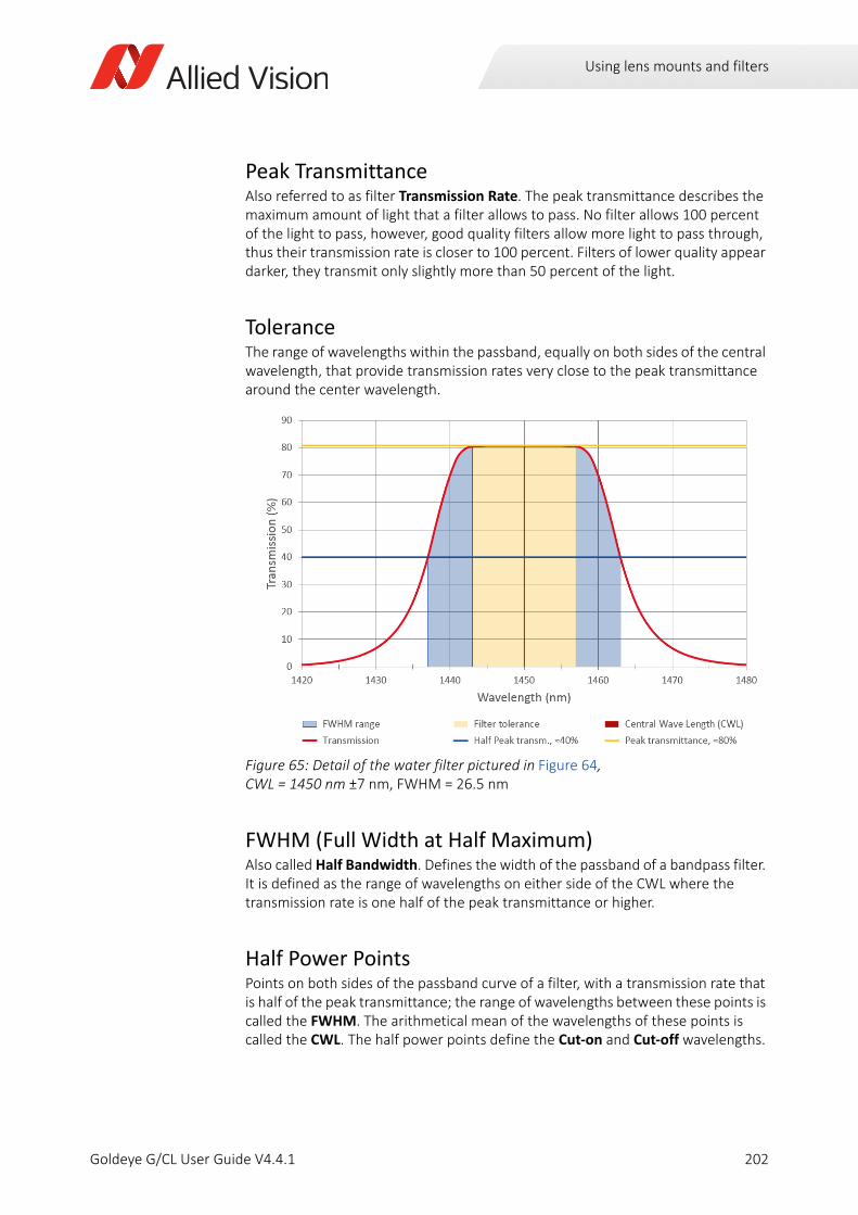
Using lens mounts and filters
Peak TransmittanceAlso referred to as filter Transmission Rate. The peak transmittance describes the maximum amount of light that a filter allows to pass. No filter allows 100 percent of the light to pass, however, good quality filters allow more light to pass through, thus their transmission rate is closer to 100 percent. Filters of lower quality appear darker, they transmit only slightly more than 50 percent of the light.
ToleranceThe range of wavelengths within the passband, equally on both sides of the central wavelength, that provide transmission rates very close to the peak transmittance around the center wavelength.
FWHM (Full Width at Half Maximum)Also called Half Bandwidth. Defines the width of the passband of a bandpass filter. It is defined as the range of wavelengths on either side of the CWL where the transmission rate is one half of the peak transmittance or higher.
Half Power PointsPoints on both sides of the passband curve of a filter, with a transmission rate that is half of the peak transmittance; the range of wavelengths between these points is called the FWHM. The arithmetical mean of the wavelengths of these points is called the CWL. The half power points define the Cut-on and Cut-off wavelengths.
Figure 65: Detail of the water filter pictured in Figure 64, CWL = 1450 nm ±7 nm, FWHM = 26.5 nm
202Goldeye G/CL User Guide V4.4.1
Using lens mounts and filters
Single and multi band filtersSingle band filters provide only one passband.Multi band filters provide two or more passbands that are separated by a rejection band.
Bandpass filters 1450 nm (water filters)As an example, the center wavelength of a water filter displayed in Figure 65 is 1450 nm with a tolerance of ±7 nm, and a FWHM bandwidth of 26.5 nm. The maximum transmission of the passband is around 80 percent. Therefore, the FWHM in this example is defined as the range of frequencies around the CWL where the transmission is 40 percent or above.
Bandpass filters 1450 nm assembled
See Bandpass filter 1450 nm (water filter) on page 184.
203Goldeye G/CL User Guide V4.4.1
Camera interfaces
Goldeye G/CL User Guide V4.4.1
This chapter includes:
GigE port, back panel, and status LEDs (GigE).................... 207CL port, back panel, and status LED (CL) ............................ 207Power supply (GigE and CL models) ................................... 209I/O description (GigE and CL models)................................. 211Frame grabber requirements (CL) ...................................... 223Timing (CL) .......................................................................... 224Starting the acquisition automatically (CL)......................... 228
204
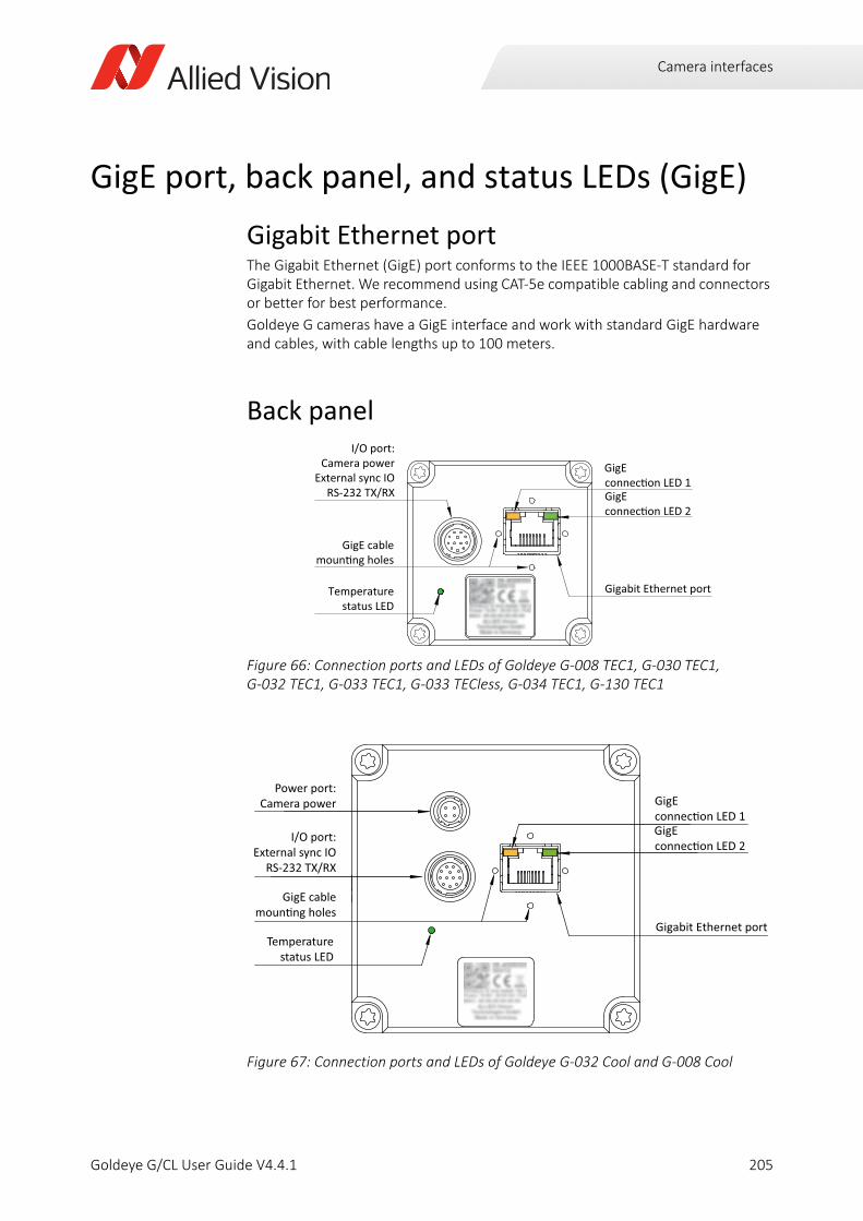
Camera interfaces
GigE port, back panel, and status LEDs (GigE)
Gigabit Ethernet portThe Gigabit Ethernet (GigE) port conforms to the IEEE 1000BASE-T standard for Gigabit Ethernet. We recommend using CAT-5e compatible cabling and connectors or better for best performance.
Goldeye G cameras have a GigE interface and work with standard GigE hardware and cables, with cable lengths up to 100 meters.
Back panel
Figure 66: Connection ports and LEDs of Goldeye G-008 TEC1, G-030 TEC1, G-032 TEC1, G-033 TEC1, G-033 TECless, G-034 TEC1, G-130 TEC1
Figure 67: Connection ports and LEDs of Goldeye G-032 Cool and G-008 Cool
Temperaturestatus LED
I/O port:Camera power
External sync IORS-232 TX/RX
GigE cable
GigE
GigE
Gigabit Ethernet port
GigE
GigE
Temperature
GigE cable
I/O port:External sync IO
Power port:Camera power
205Goldeye G/CL User Guide V4.4.1
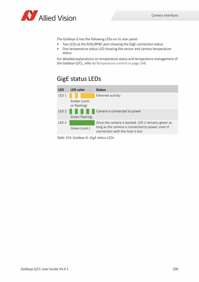
Camera interfaces
The Goldeye G has the following LEDs on its rear panel:
• Two LEDs at the RJ45/8P8C port showing the GigE connection status.
• One temperature status LED showing the sensor and camera temperature status.
For detailed explanations on temperature status and temperature management of the Goldeye G/CL, refer to Temperature control on page 248.
GigE status LEDs
LED LED color Status
LED 1 Ethernet activity
Amber (cont.or flashing)
LED 2 Camera is connected to power
Green flashing
LED 2 Once the camera is booted, LED 2 remains green as long as the camera is connected to power, even if connection with the host is lost.
Green (cont.)
Table 154: Goldeye G: GigE status LEDs
206Goldeye G/CL User Guide V4.4.1
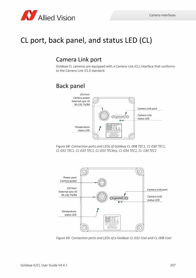
Camera interfaces
CL port, back panel, and status LED (CL)
Camera Link portGoldeye CL cameras are equipped with a Camera Link (CL) interface that conforms to the Camera Link V2.0 standard.
Back panel
Figure 68: Connection ports and LEDs of Goldeye CL-008 TEC1, CL-030 TEC1,CL-032 TEC1, CL-033 TEC1, CL-033 TECless, CL-034 TEC1, CL-130 TEC1
Figure 69: Connection ports and LEDs of a Goldeye CL-032 Cool and CL-008 Cool
Temperaturestatus LED
I/O Port:Camera power
External sync IORS-232 TX/RX
Camera Linkstatus LED
Camera Link port
Temperaturestatus LED
I/O Port:External sync IO
RS-232 TX/RX
Power port:Camera power
Camera Linkstatus LED
Camera Link port
207Goldeye G/CL User Guide V4.4.1
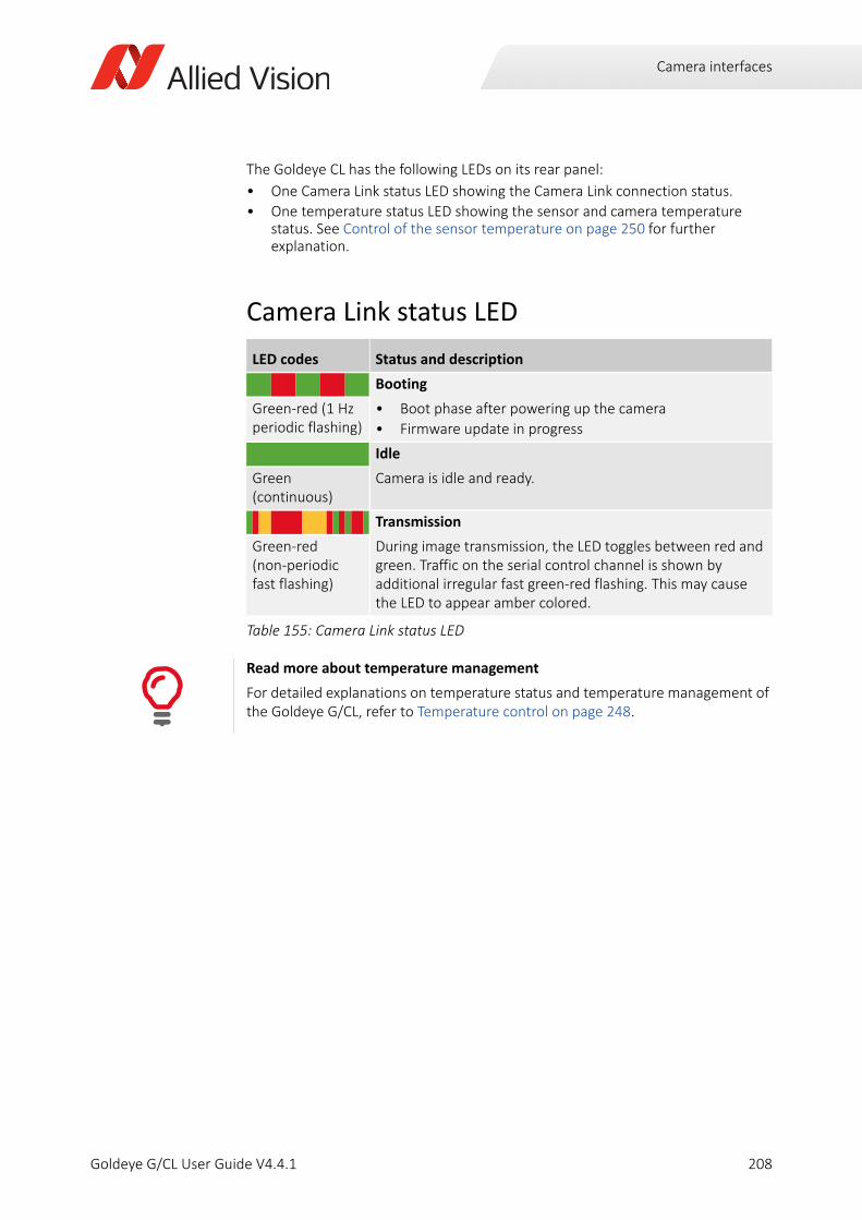
Camera interfaces
The Goldeye CL has the following LEDs on its rear panel:
• One Camera Link status LED showing the Camera Link connection status.
• One temperature status LED showing the sensor and camera temperature status. See Control of the sensor temperature on page 250 for further explanation.
Camera Link status LED
LED codes Status and description
Booting
• Boot phase after powering up the camera
• Firmware update in progress
Green-red (1 Hz periodic flashing)
Idle
Camera is idle and ready.Green (continuous)
Transmission
During image transmission, the LED toggles between red and green. Traffic on the serial control channel is shown by additional irregular fast green-red flashing. This may cause the LED to appear amber colored.
Green-red (non-periodic fast flashing)
Table 155: Camera Link status LED
Read more about temperature management
For detailed explanations on temperature status and temperature management of the Goldeye G/CL, refer to Temperature control on page 248.
208Goldeye G/CL User Guide V4.4.1
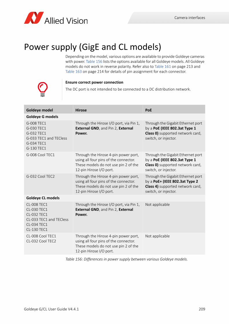
Camera interfaces
Power supply (GigE and CL models)Depending on the model, various options are available to provide Goldeye cameras with power. Table 156 lists the options available for all Goldeye models. All Goldeye models do not work in reverse polarity. Refer also to Table 161 on page 213 and Table 163 on page 214 for details of pin assignment for each connector.
Ensure correct power connection
The DC port is not intended to be connected to a DC distribution network.
Goldeye model Hirose PoE
Goldeye G models
G-008 TEC1G-030 TEC1G-032 TEC1 G-033 TEC1 and TEClessG-034 TEC1G-130 TEC1
Through the Hirose I/O port, via Pin 1, External GND, and Pin 2, External Power.
Through the Gigabit Ethernet port by a PoE (IEEE 802.3at Type 1 Class 0) supported network card, switch, or injector.
G-008 Cool TEC1 Through the Hirose 4-pin power port, using all four pins of the connector. These models do not use pin 2 of the 12-pin Hirose I/O port.
Through the Gigabit Ethernet port by a PoE (IEEE 802.3at Type 1 Class 0) supported network card, switch, or injector.
G-032 Cool TEC2 Through the Hirose 4-pin power port, using all four pins of the connector. These models do not use pin 2 of the 12-pin Hirose I/O port.
Through the Gigabit Ethernet port by a PoE+ (IEEE 802.3at Type 2 Class 4) supported network card, switch, or injector.
Goldeye CL models
CL-008 TEC1CL-030 TEC1 CL-032 TEC1CL-033 TEC1 and TEClessCL-034 TEC1CL-130 TEC1
Through the Hirose I/O port, via Pin 1, External GND, and Pin 2, External Power.
Not applicable
CL-008 Cool TEC1CL-032 Cool TEC2
Through the Hirose 4-pin power port, using all four pins of the connector. These models do not use pin 2 of the 12-pin Hirose I/O port.
Not applicable
Table 156: Differences in power supply between various Goldeye models.
209Goldeye G/CL User Guide V4.4.1
Camera interfaces
Power supply via Hirose connector
Industrial design Goldeye models (using the I/O port)Use one of the following connections.
• Power supply with Hirose 12-pin connector
• I/O cable with Hirose 12-pin connector in conjunction with a standard power supply adapter
Goldeye Cool models (using the power port)Use one of the following connections:
• Power supply with Hirose 4-pin connector
• Power cable with Hirose 4-pin connector in conjunction with a standard power supply adapter.
You cannot use the Hirose 12-pin I/O connector to supply Goldeye Cool models with power.
Power supply via Gigabit Ethernet (Goldeye G only)You can supply Goldeye G models with power through the Gigabit Ethernet port by using any standard Power over Ethernet (PoE or PoE+) supported network connection.
The pin assignment of the RJ45/8P8C connector is according to the Ethernet Standard (IEEE 802.3 1000BASE-T), which supports cable lengths of up to 100 meters. All Goldeye G models can obtain power from IEEE 802.3at compliant Power Sourcing Equipment (PSE) devices, such as switches, injectors, or NICs.
If any Hirose connector provides a valid DC voltage to the camera, and the GigE connector is connected via PoE at the same time, the camera obtains power from the Hirose connector only.
Ensure a correct power supply
In case the camera is provided with power via the I/O connector, always ensure that the voltage at the camera input lies within the designated requirement of 10.8 V to 30.0 V.
Goldeye G models: Minimizing Power consumption
If the camera operates under higher temperature conditions, you should consider powering the camera via the I/O connector instead of PoE, because PoE contributes to the heat build-up inside the camera.
Refer to Specifications (GigE models) on page 75 for details on power consumption.
210Goldeye G/CL User Guide V4.4.1
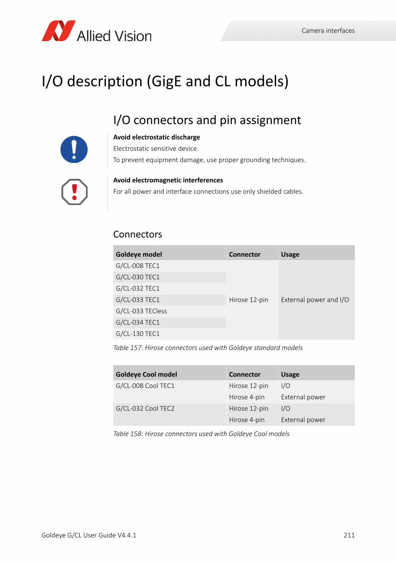
Camera interfaces
I/O description (GigE and CL models)
I/O connectors and pin assignment
Connectors
Avoid electrostatic discharge
Electrostatic sensitive device.
To prevent equipment damage, use proper grounding techniques.
Avoid electromagnetic interferences
For all power and interface connections use only shielded cables.
Goldeye model Connector Usage
G/CL-008 TEC1
Hirose 12-pin External power and I/O
G/CL-030 TEC1
G/CL-032 TEC1
G/CL-033 TEC1
G/CL-033 TECless
G/CL-034 TEC1
G/CL-130 TEC1
Table 157: Hirose connectors used with Goldeye standard models
Goldeye Cool model Connector Usage
G/CL-008 Cool TEC1 Hirose 12-pin
Hirose 4-pin
I/O
External power
G/CL-032 Cool TEC2 Hirose 12-pin
Hirose 4-pin
I/O
External power
Table 158: Hirose connectors used with Goldeye Cool models
211Goldeye G/CL User Guide V4.4.1
Camera interfaces
I/O types
Non-isolated I/Os
• One non-isolated line-in (3.3 V LVTTL, 5 V TTL tolerated, see Table 161 on page 213)
• One non-isolated line-out (5 V TTL)
• (Camera Link only) Four non-isolated LVDS inputs (CC ports)
Opto-isolated I/Os
• One opto-isolated line-in
• Two opto-isolated line-out
• Maximum isolated power voltage is 30 V
• Line-in voltages:
- Vin(low) = 0.0 V to 1.0 V
- Vin(high) = 3.0 V to 24.0 V
Trigger cables with 12-pin Hirose connector (overview)Cable side Hirose connectors (without cable) and I/O cables with Hirose connector are available for purchase from Allied Vision.
If you use other I/O cables, the maximum length of the I/O cable must not exceed 30 meters.
Product code Description
1068908 Trigger cable In1 BNC LVTTL with Hirose 12-pin connector, 2 m
1068909 Trigger cable In1 BNC LVTTL with Hirose 12-pin connector, 5 m
Table 159: Available trigger cables with Hirose 12-pin connector
212Goldeye G/CL User Guide V4.4.1
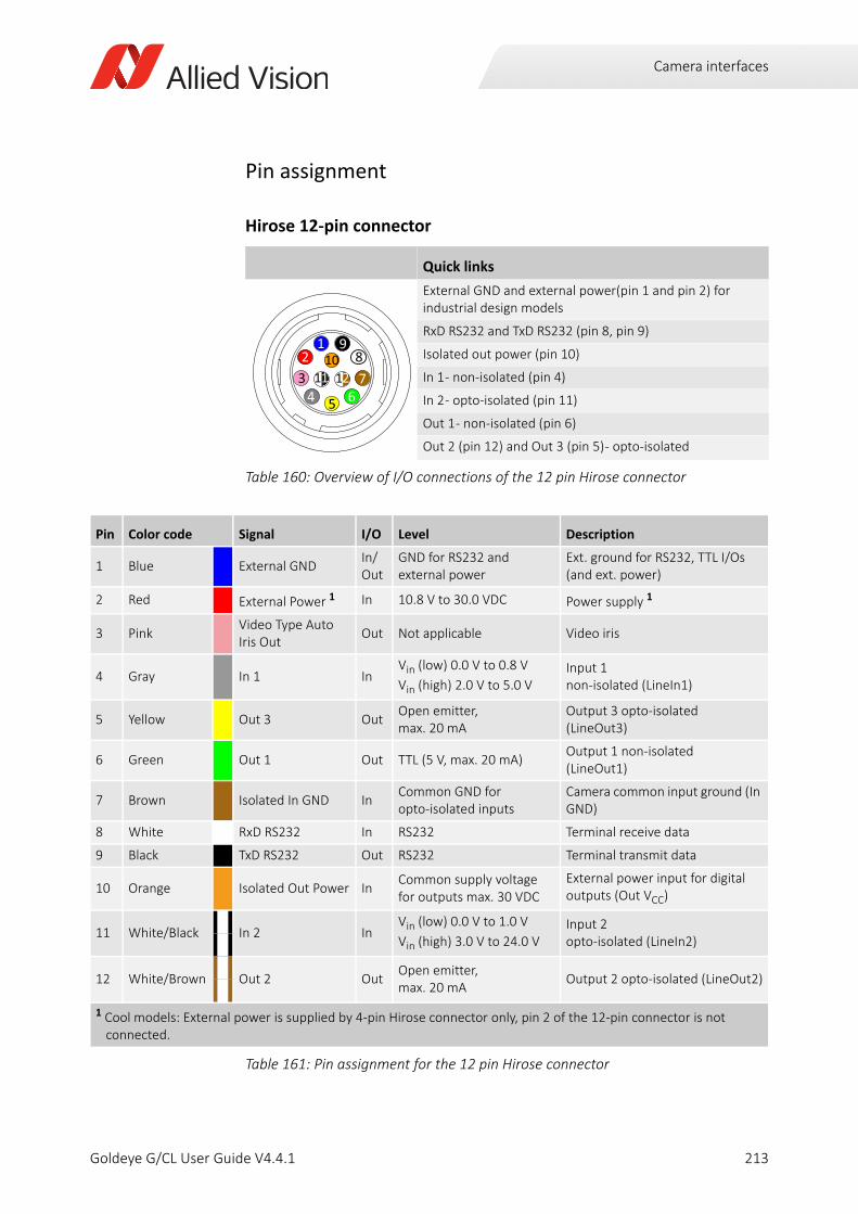
Camera interfaces
Pin assignment
Hirose 12-pin connector
Quick links
External GND and external power(pin 1 and pin 2) for industrial design models
RxD RS232 and TxD RS232 (pin 8, pin 9)
Isolated out power (pin 10)
In 1 - non-isolated (pin 4)
In 2 - opto-isolated (pin 11)
Out 1 - non-isolated (pin 6)
Out 2 (pin 12) and Out 3 (pin 5) - opto-isolated
Table 160: Overview of I/O connections of the 12 pin Hirose connector
Pin Color code Signal I/O Level Description
1 Blue External GND In/ Out
GND for RS232 and external power
Ext. ground for RS232, TTL I/Os (and ext. power)
2 Red External Power 1 In 10.8 V to 30.0 VDC Power supply 1
3 PinkVideo Type Auto Iris Out
Out Not applicable Video iris
4 Gray In 1 InVin (low) 0.0 V to 0.8 V
Vin (high) 2.0 V to 5.0 VInput 1non-isolated (LineIn1)
5 Yellow Out 3 OutOpen emitter, max. 20 mA
Output 3 opto-isolated (LineOut3)
6 Green Out 1 Out TTL (5 V, max. 20 mA)Output 1 non-isolated (LineOut1)
7 Brown Isolated In GND InCommon GND for opto-isolated inputs
Camera common input ground (In GND)
8 White RxD RS232 In RS232 Terminal receive data
9 Black TxD RS232 Out RS232 Terminal transmit data
10 Orange Isolated Out Power InCommon supply voltage for outputs max. 30 VDC
External power input for digital outputs (Out VCC)
11 White/Black In 2 InVin (low) 0.0 V to 1.0 V
Vin (high) 3.0 V to 24.0 VInput 2opto-isolated (LineIn2)
12 White/Brown Out 2 OutOpen emitter,max. 20 mA
Output 2 opto-isolated (LineOut2)
1 Cool models: External power is supplied by 4-pin Hirose connector only, pin 2 of the 12-pin connector is not connected.
Table 161: Pin assignment for the 12 pin Hirose connector
2
6543
107
891
11 12
213Goldeye G/CL User Guide V4.4.1
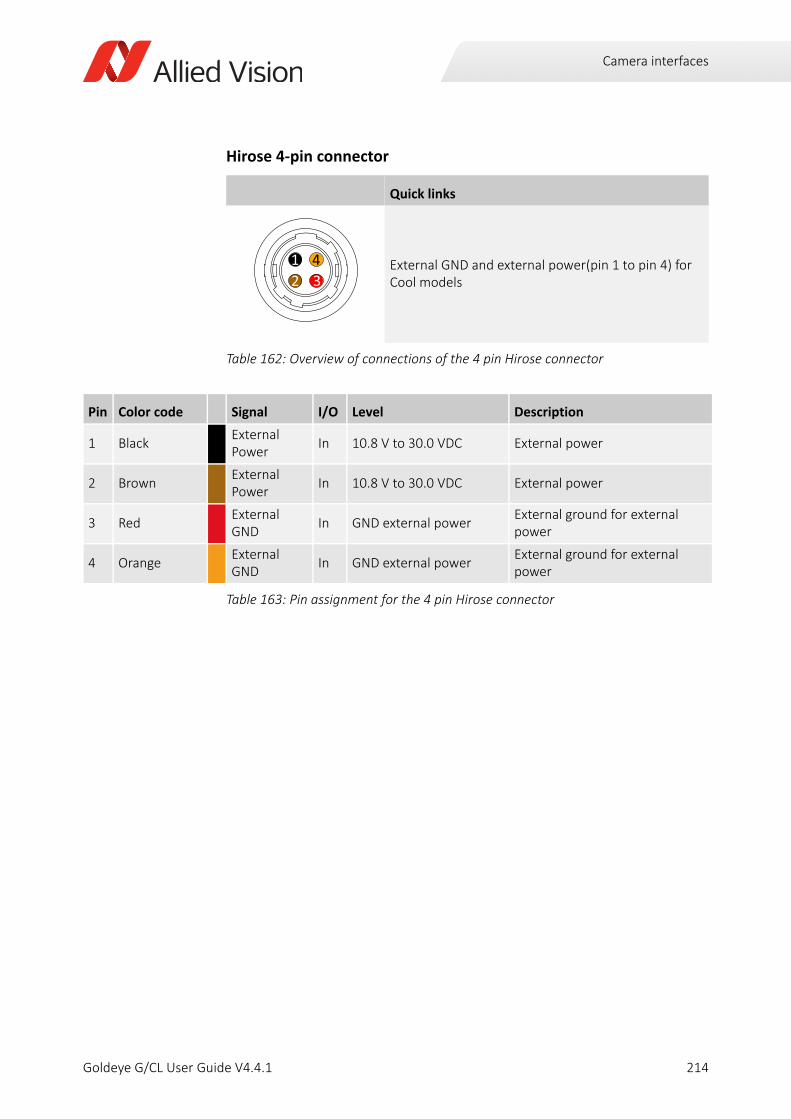
Camera interfaces
Hirose 4-pin connector
Quick links
External GND and external power(pin 1 to pin 4) for Cool models
Table 162: Overview of connections of the 4 pin Hirose connector
Pin Color code Signal I/O Level Description
1 BlackExternal Power
In 10.8 V to 30.0 VDC External power
2 BrownExternal Power
In 10.8 V to 30.0 VDC External power
3 RedExternal GND
In GND external powerExternal ground for external power
4 OrangeExternal GND
In GND external powerExternal ground for external power
Table 163: Pin assignment for the 4 pin Hirose connector
12 3
4
214Goldeye G/CL User Guide V4.4.1
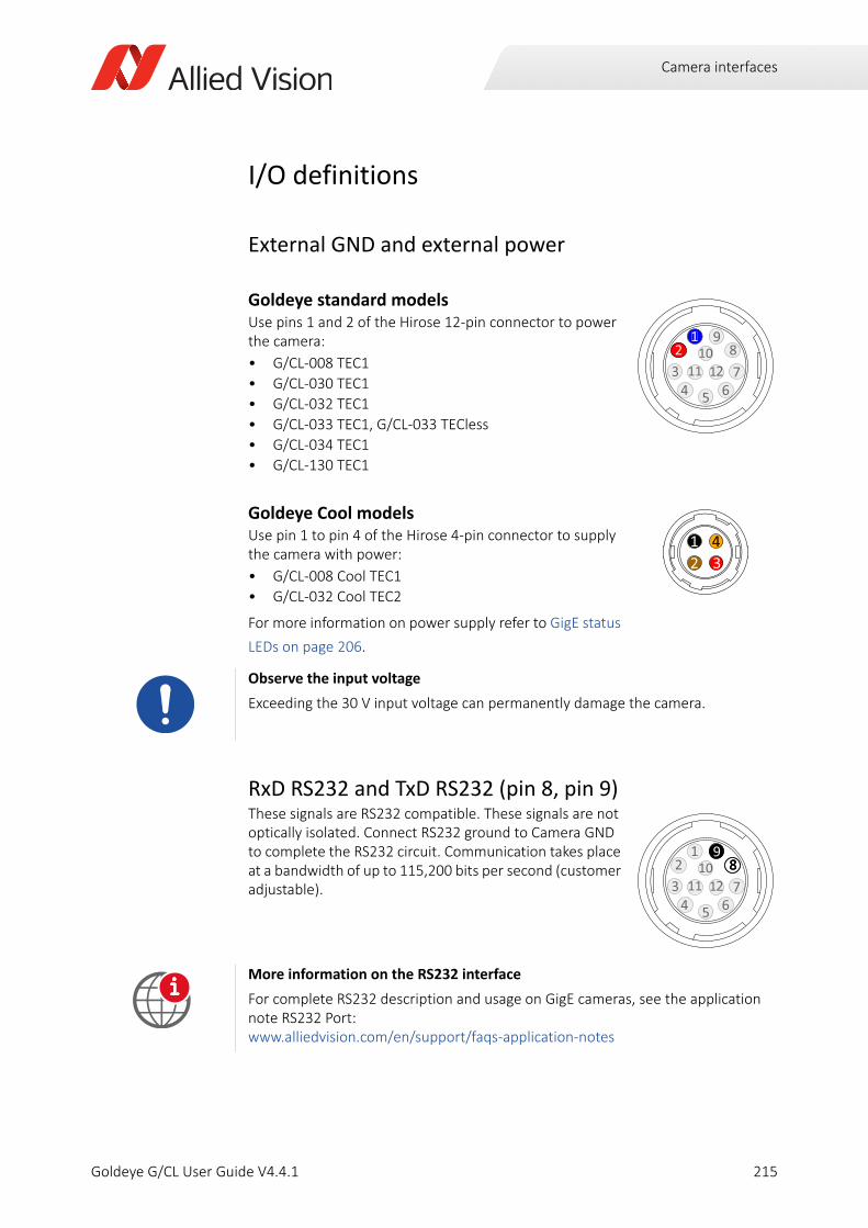
Camera interfaces
I/O definitions
External GND and external power
Goldeye standard modelsUse pins 1 and 2 of the Hirose 12-pin connector to power the camera:
• G/CL-008 TEC1
• G/CL-030 TEC1
• G/CL-032 TEC1
• G/CL-033 TEC1, G/CL-033 TECless
• G/CL-034 TEC1
• G/CL-130 TEC1
Goldeye Cool modelsUse pin 1 to pin 4 of the Hirose 4-pin connector to supply the camera with power:
• G/CL-008 Cool TEC1
• G/CL-032 Cool TEC2
For more information on power supply refer to GigE status
LEDs on page 206.
RxD RS232 and TxD RS232 (pin 8, pin 9)These signals are RS232 compatible. These signals are not optically isolated. Connect RS232 ground to Camera GND to complete the RS232 circuit. Communication takes place at a bandwidth of up to 115,200 bits per second (customer adjustable).
Observe the input voltage
Exceeding the 30 V input voltage can permanently damage the camera.
More information on the RS232 interface
For complete RS232 description and usage on GigE cameras, see the application note RS232 Port:www.alliedvision.com/en/support/faqs-application-notes
2
65413
107
891
11 2
112
12 3
4
2
65413
107
891
11 2
988
i
215Goldeye G/CL User Guide V4.4.1
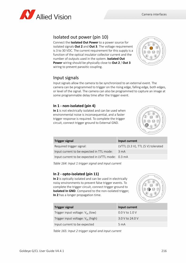
Camera interfaces
Isolated out power (pin 10)Connect the Isolated Out Power to a power source for isolated signals Out 2 and Out 3. The voltage requirement is 3 to 30 VDC. The current requirement for this supply is a function of the optical insulator collector current and the number of outputs used in the system. Isolated Out Power wiring should be physically close to Out 2 / Out 3 wiring to prevent parasitic coupling.
Input signalsInput signals allow the camera to be synchronized to an external event. The camera can be programmed to trigger on the rising edge, falling edge, both edges, or level of the signal. The camera can also be programmed to capture an image at some programmable delay time after the trigger event.
In 1 - non-isolated (pin 4)In 1 is not electrically isolated and can be used when environmental noise is inconsequential, and a faster trigger response is required. To complete the trigger circuit, connect trigger ground to External GND.
In 2 - opto-isolated (pin 11)In 2 is optically isolated and can be used in electrically noisy environments to prevent false trigger events. To complete the trigger circuit, connect trigger ground to Isolated In GND. Compared to the non-isolated trigger, In 2 has a longer propagation time.
Trigger signal Input current
Required trigger signal: LVTTL (3.3 V), TTL (5 V) tolerated
Input current to be expected in TTL mode: 3 mA
Input current to be expected in LVTTL mode: 0.3 mA
Table 164: Input 1 trigger signal and input current
Trigger signal Input current
Trigger input voltage: Vin (low) 0.0 V to 1.0 V
Trigger input voltage: Vin (high) 3.0 V to 24.0 V
Input current to be expected 5 mA
Table 165: Input 2 trigger signal and input current
2
65413
107
891
11 210
2
65413
107
891
11 24
2
65413
107
891
11 211
216Goldeye G/CL User Guide V4.4.1
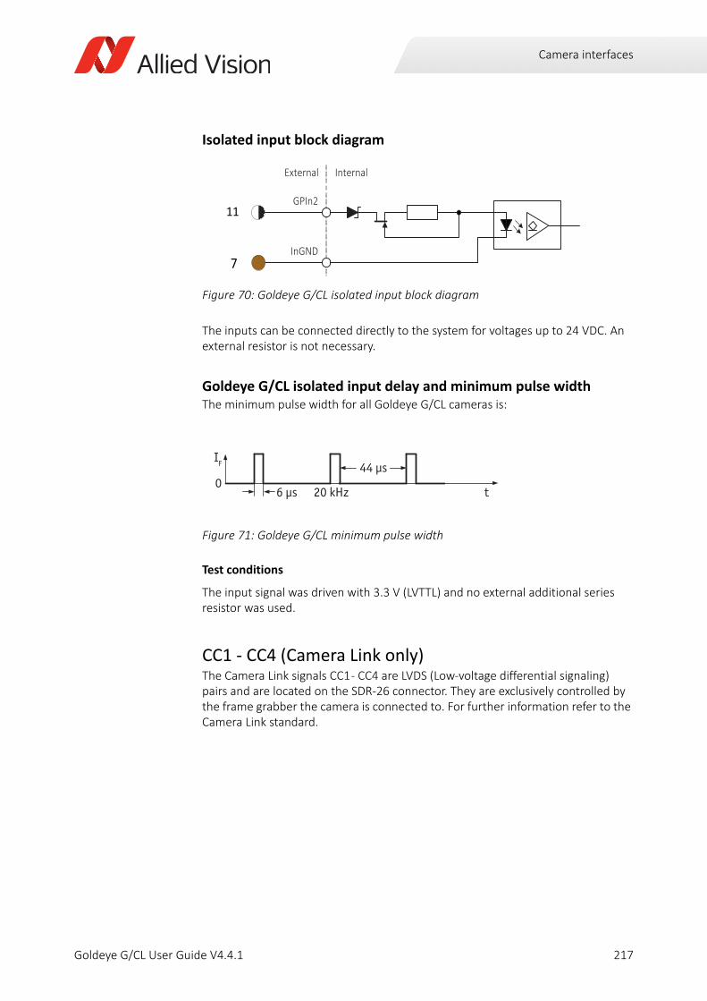
Camera interfaces
Isolated input block diagram
The inputs can be connected directly to the system for voltages up to 24 VDC. An external resistor is not necessary.
Goldeye G/CL isolated input delay and minimum pulse widthThe minimum pulse width for all Goldeye G/CL cameras is:
Test conditions
The input signal was driven with 3.3 V (LVTTL) and no external additional series resistor was used.
CC1 - CC4 (Camera Link only)The Camera Link signals CC1 - CC4 are LVDS (Low-voltage differential signaling) pairs and are located on the SDR-26 connector. They are exclusively controlled by the frame grabber the camera is connected to. For further information refer to the Camera Link standard.
Figure 70: Goldeye G/CL isolated input block diagram
Figure 71: Goldeye G/CL minimum pulse width
InGND
External Internal
GPIn211
7
IF
0t
44 μs
6 μs 20 kHz
217Goldeye G/CL User Guide V4.4.1
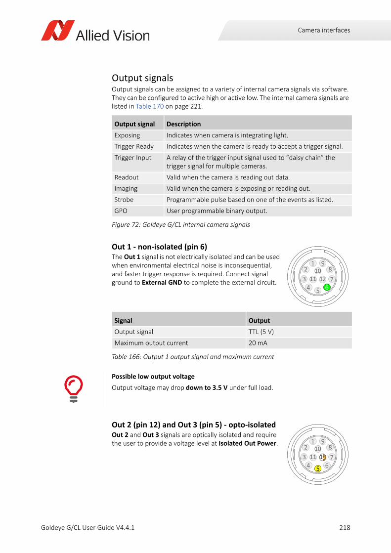
Camera interfaces
Output signalsOutput signals can be assigned to a variety of internal camera signals via software. They can be configured to active high or active low. The internal camera signals are listed in Table 170 on page 221.
Out 1 - non-isolated (pin 6)The Out 1 signal is not electrically isolated and can be used when environmental electrical noise is inconsequential, and faster trigger response is required. Connect signal ground to External GND to complete the external circuit.
Out 2 (pin 12) and Out 3 (pin 5) - opto-isolatedOut 2 and Out 3 signals are optically isolated and require the user to provide a voltage level at Isolated Out Power.
Output signal Description
Exposing Indicates when camera is integrating light.
Trigger Ready Indicates when the camera is ready to accept a trigger signal.
Trigger Input A relay of the trigger input signal used to “daisy chain” the trigger signal for multiple cameras.
Readout Valid when the camera is reading out data.
Imaging Valid when the camera is exposing or reading out.
Strobe Programmable pulse based on one of the events as listed.
GPO User programmable binary output.
Figure 72: Goldeye G/CL internal camera signals
Signal Output
Output signal TTL (5 V)
Maximum output current 20 mA
Table 166: Output 1 output signal and maximum current
Possible low output voltage
Output voltage may drop down to 3.5 V under full load.
2
65413
107
891
11 26
2
65413
107
891
11 2
5
12
218Goldeye G/CL User Guide V4.4.1
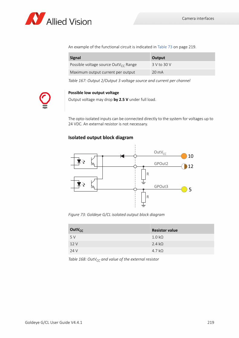
Camera interfaces
An example of the functional circuit is indicated in Table 73 on page 219.
The opto-isolated inputs can be connected directly to the system for voltages up to 24 VDC. An external resistor is not necessary.
Isolated output block diagram
Signal Output
Possible voltage source OutVCC Range 3 V to 30 V
Maximum output current per output 20 mA
Table 167: Output 2/Output 3 voltage source and current per channel
Possible low output voltage
Output voltage may drop by 2.5 V under full load.
Figure 73: Goldeye G/CL isolated output block diagram
OutVCC Resistor value
5 V 1.0 kΩ
12 V 2.4 kΩ
24 V 4.7 kΩ
Table 168: OutVCC and value of the external resistor
OutV
GPOut2
GPOut3
R
R
CC
12
5
10
219Goldeye G/CL User Guide V4.4.1
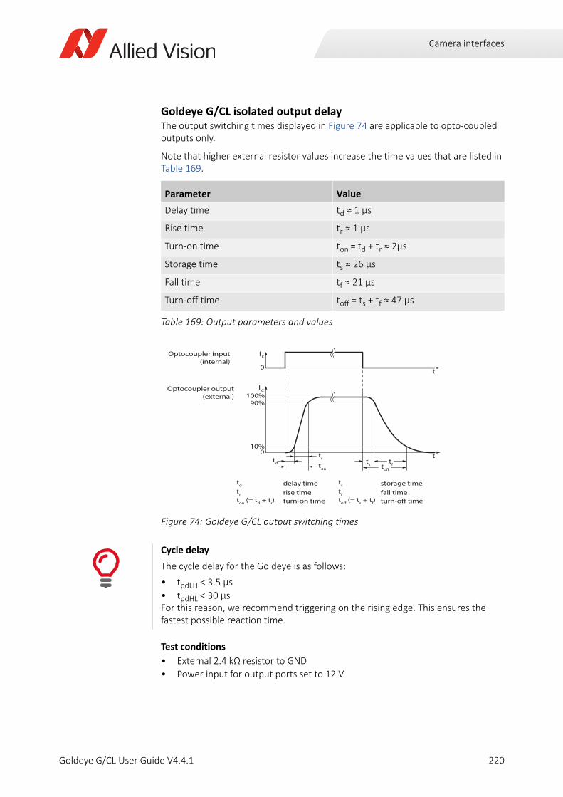
Camera interfaces
Goldeye G/CL isolated output delayThe output switching times displayed in Figure 74 are applicable to opto-coupled outputs only.
Note that higher external resistor values increase the time values that are listed in Table 169.
Test conditions
• External 2.4 kΩ resistor to GND
• Power input for output ports set to 12 V
Parameter Value
Delay time td ≈ 1 μs
Rise time tr ≈ 1 µs
Turn-on time ton = td + tr ≈ 2µs
Storage time ts ≈ 26 µs
Fall time tf ≈ 21 µs
Turn-off time toff = ts + tf ≈ 47 µs
Table 169: Output parameters and values
Figure 74: Goldeye G/CL output switching times
Cycle delay
The cycle delay for the Goldeye is as follows:
• tpdLH < 3.5 µs
• tpdHL < 30 µsFor this reason, we recommend triggering on the rising edge. This ensures the fastest possible reaction time.
I F
0
I C
100%90%
10%
t
t0
delay timerise timeturn-on time
storage timefall timeturn-off time
Optocoupler input(internal)
Optocoupler output(external)
toff (= ts + tf)
td
tr
ton (= td + tr)
ts
tf
td ton
trts tftoff
220Goldeye G/CL User Guide V4.4.1
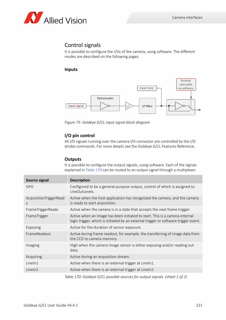
Camera interfaces
Control signals It is possible to configure the I/Os of the camera, using software. The different modes are described on the following pages.
Inputs
I/O pin controlAll I/O signals running over the camera I/O connector are controlled by the I/O strobe commands. For more details see the Goldeye G/CL Features Reference.
OutputsIt is possible to configure the output signals, using software. Each of the signals explained in Table 170 can be routed to an output signal through a multiplexer.
Figure 75: Goldeye G/CL input signal block diagram
Source signal Description
GPO Configured to be a general-purpose output, control of which is assigned to LineOutLevels.
AcquisitionTriggerReady
Active when the host application has recognized the camera, and the camera is ready to start acquisition.
FrameTriggerReady Active when the camera is in a state that accepts the next frame trigger.
FrameTrigger Active when an image has been initiated to start. This is a camera-internal logic trigger, which is initiated by an external trigger or software trigger event.
Exposing Active for the duration of sensor exposure.
FrameReadout Active during frame readout, for example, the transferring of image data from the CCD to camera memory.
Imaging High when the camera image sensor is either exposing and/or reading out data.
Acquiring Active during an acquisition stream.
LineIn1 Active when there is an external trigger at LineIn1.
LineIn2 Active when there is an external trigger at LineIn2.
Table 170: Goldeye G/CL possible sources for output signals (sheet 1 of 2)
221Goldeye G/CL User Guide V4.4.1
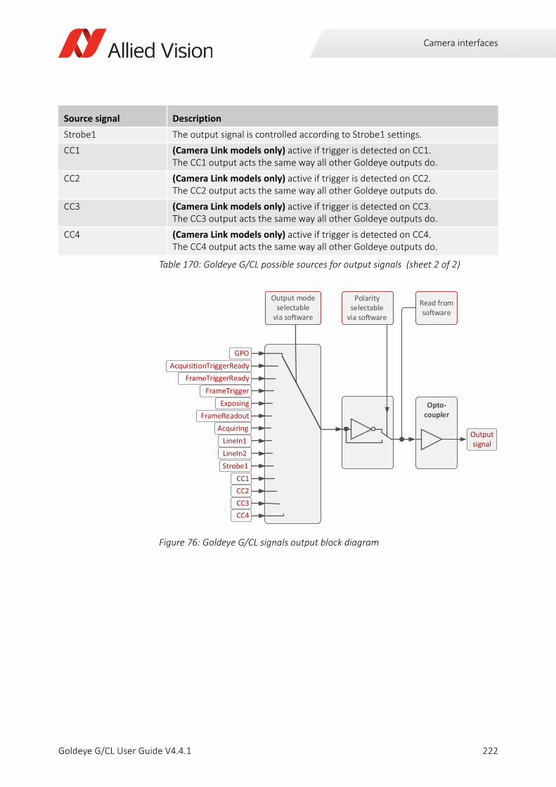
Camera interfaces
Strobe1 The output signal is controlled according to Strobe1 settings.
CC1 (Camera Link models only) active if trigger is detected on CC1. The CC1 output acts the same way all other Goldeye outputs do.
CC2 (Camera Link models only) active if trigger is detected on CC2. The CC2 output acts the same way all other Goldeye outputs do.
CC3 (Camera Link models only) active if trigger is detected on CC3. The CC3 output acts the same way all other Goldeye outputs do.
CC4 (Camera Link models only) active if trigger is detected on CC4. The CC4 output acts the same way all other Goldeye outputs do.
Figure 76: Goldeye G/CL signals output block diagram
Source signal Description
Table 170: Goldeye G/CL possible sources for output signals (sheet 2 of 2)
GPOAcquisi onTriggerReady
FrameTriggerReadyFrameTrigger
ExposingFrameReadout
AcquiringLineIn1LineIn2Strobe1
Read from so ware
Output signal
Output modeselectable
via so ware
Opto-coupler
Polarityselectable
via so ware
CC1CC2CC3CC4
222Goldeye G/CL User Guide V4.4.1
Camera interfaces
Frame grabber requirements (CL)You can use basically any Camera Link Base compatible frame grabber to operate Goldeye CL cameras. However, the following general aspects should be considered for frame grabber selection:
• The frame grabber needs to support the individual pixel clock frequency of the camera (which may be up to 85 MHz, depending on the model). See also Changing the clock frequency on page 224.
• The frame grabber and the host system need to support the pixel data bandwidth delivered by the camera.
Depending on model and operation mode, a Camera Link Base camera may be able to output up to approximately 170 million 12-bit pixels per second. Assuming a worst-case scenario of unpacked 16 bits per pixel transfer over the host bus, this results in 340 million bytes per second. This is approximately three times the bandwidth of a Gigabit Ethernet port.
• Host software design and system architecture usually affect frame grabber selection as well, for instance the number of cameras connected to the host, the different types of cameras connected, or the availability of a frame grabber specific GenICam transport layer.
• A high transmission rate support (> 115 200 bits per second) of the Camera Link serial port is recommended to improve responsiveness of host software.
More information about frame grabbers
For more information about compatibility of various frame grabber models and system installation refer to the following sources.
• Installing the camera (CL) on page 51
• The application note Usage of Frame grabbers with Goldeye CL Cameras is available for download on the Allied Vision website:www.alliedvision.com/en/support/technical-documentation/goldeye-gcl-documentation
i
223Goldeye G/CL User Guide V4.4.1
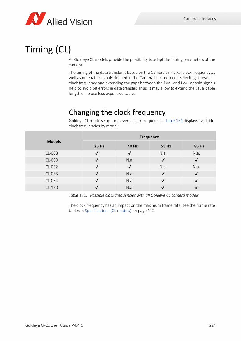
Camera interfaces
Timing (CL)All Goldeye CL models provide the possibility to adapt the timing parameters of the camera.
The timing of the data transfer is based on the Camera Link pixel clock frequency as well as on enable signals defined in the Camera Link protocol. Selecting a lower clock frequency and extending the gaps between the FVAL and LVAL enable signals help to avoid bit errors in data transfer. Thus, it may allow to extend the usual cable length or to use less expensive cables.
Changing the clock frequencyGoldeye CL models support several clock frequencies. Table 171 displays available clock frequencies by model:
The clock frequency has an impact on the maximum frame rate, see the frame rate tables in Specifications (CL models) on page 112.
ModelsFrequency
25 Hz 40 Hz 55 Hz 85 Hz
CL-008 N.a. N.a.
CL-030 N.a. CL-032 N.a. N.a.
CL-033 N.a. CL-034 N.a. CL-130 N.a.
Table 171: Possible clock frequencies with all Goldeye CL camera models.
224Goldeye G/CL User Guide V4.4.1
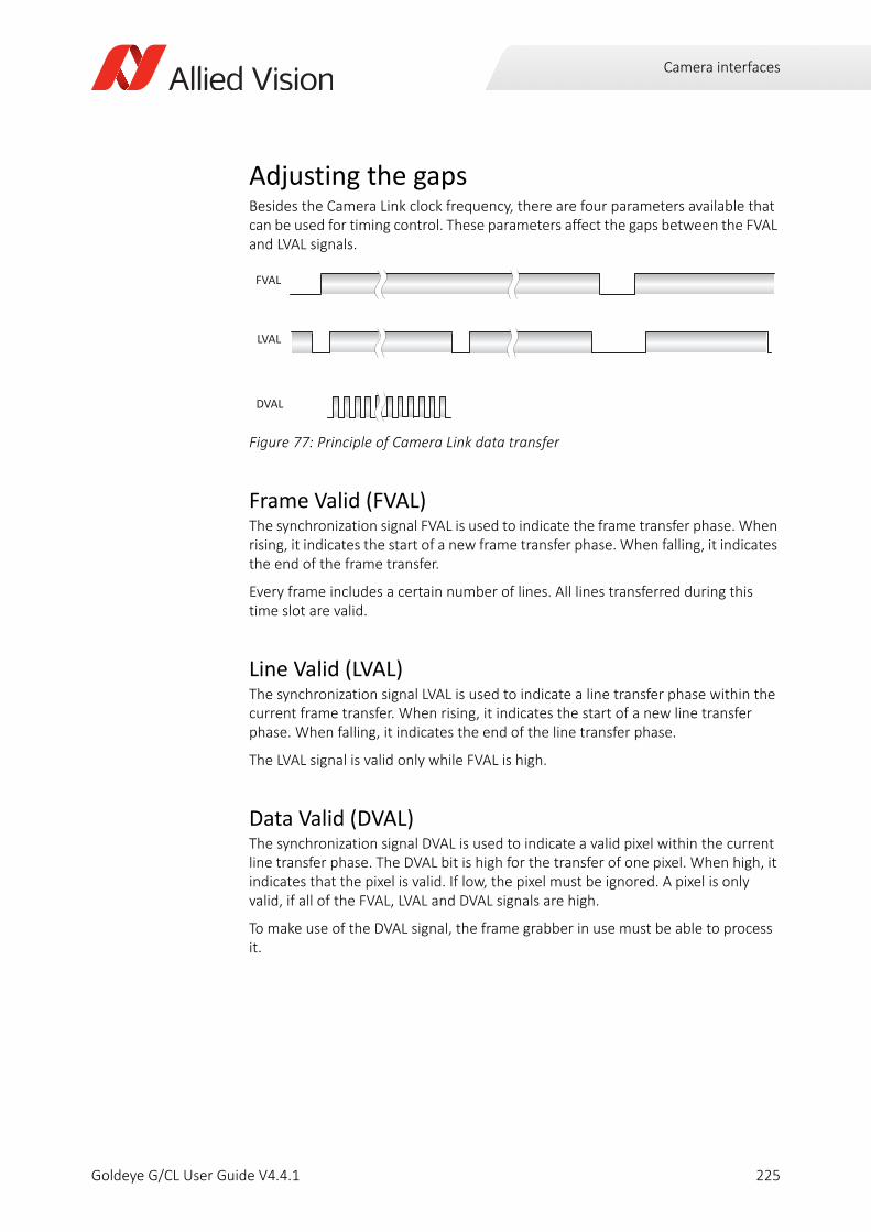
Camera interfaces
Adjusting the gapsBesides the Camera Link clock frequency, there are four parameters available that can be used for timing control. These parameters affect the gaps between the FVAL and LVAL signals.
Frame Valid (FVAL)The synchronization signal FVAL is used to indicate the frame transfer phase. When rising, it indicates the start of a new frame transfer phase. When falling, it indicates the end of the frame transfer.
Every frame includes a certain number of lines. All lines transferred during this time slot are valid.
Line Valid (LVAL)The synchronization signal LVAL is used to indicate a line transfer phase within the current frame transfer. When rising, it indicates the start of a new line transfer phase. When falling, it indicates the end of the line transfer phase.
The LVAL signal is valid only while FVAL is high.
Data Valid (DVAL)The synchronization signal DVAL is used to indicate a valid pixel within the current line transfer phase. The DVAL bit is high for the transfer of one pixel. When high, it indicates that the pixel is valid. If low, the pixel must be ignored. A pixel is only valid, if all of the FVAL, LVAL and DVAL signals are high.
To make use of the DVAL signal, the frame grabber in use must be able to process it.
Figure 77: Principle of Camera Link data transfer
FVAL
LVAL
DVAL
225Goldeye G/CL User Guide V4.4.1
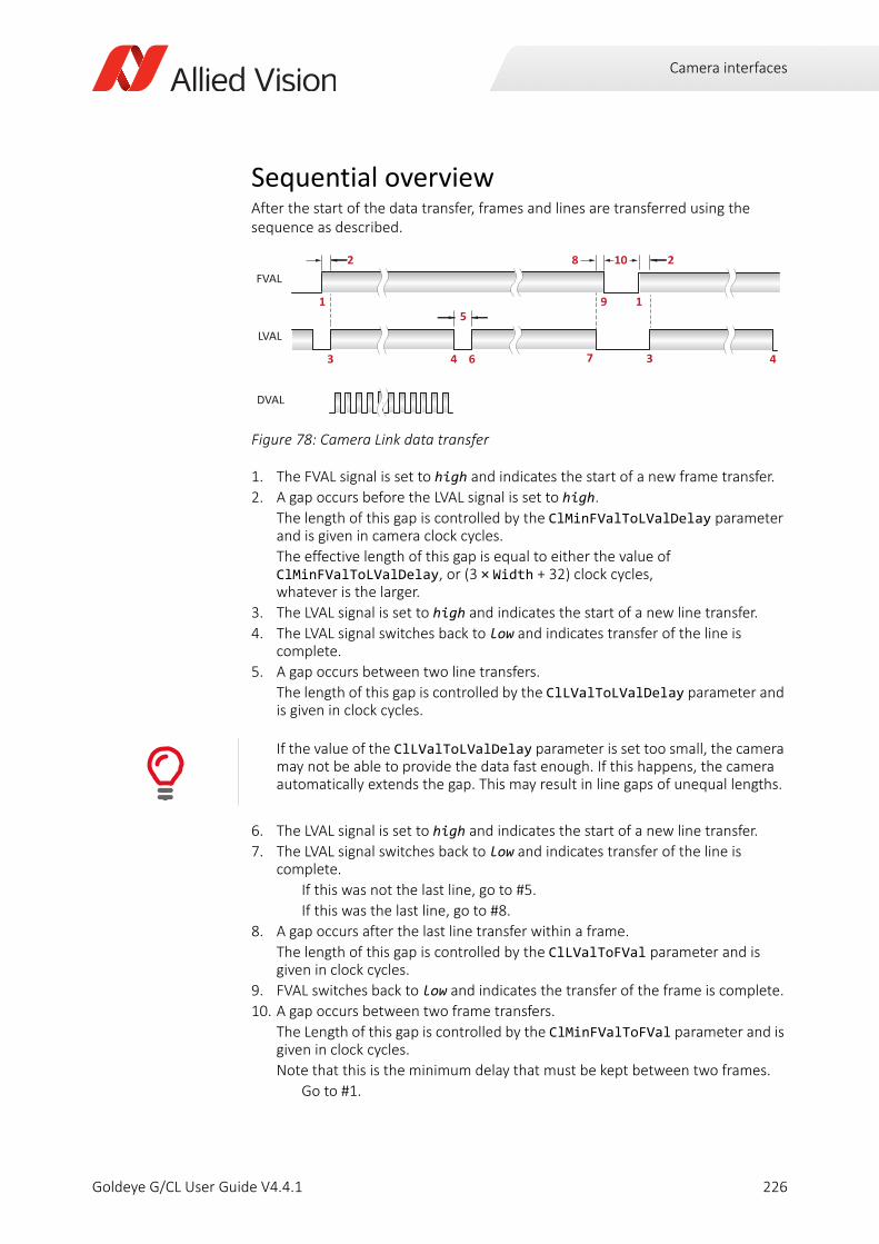
Camera interfaces
Sequential overviewAfter the start of the data transfer, frames and lines are transferred using the sequence as described.
1. The FVAL signal is set to high and indicates the start of a new frame transfer.
2. A gap occurs before the LVAL signal is set to high.
The length of this gap is controlled by the ClMinFValToLValDelay parameter and is given in camera clock cycles.
The effective length of this gap is equal to either the value of ClMinFValToLValDelay, or (3 × Width + 32) clock cycles, whatever is the larger.
3. The LVAL signal is set to high and indicates the start of a new line transfer.
4. The LVAL signal switches back to low and indicates transfer of the line is complete.
5. A gap occurs between two line transfers.
The length of this gap is controlled by the ClLValToLValDelay parameter and is given in clock cycles.
6. The LVAL signal is set to high and indicates the start of a new line transfer.
7. The LVAL signal switches back to low and indicates transfer of the line is complete.
If this was not the last line, go to #5.
If this was the last line, go to #8.
8. A gap occurs after the last line transfer within a frame.
The length of this gap is controlled by the ClLValToFVal parameter and is given in clock cycles.
9. FVAL switches back to low and indicates the transfer of the frame is complete.
10. A gap occurs between two frame transfers.
The Length of this gap is controlled by the ClMinFValToFVal parameter and is given in clock cycles.
Note that this is the minimum delay that must be kept between two frames.
Go to #1.
Figure 78: Camera Link data transfer
If the value of the ClLValToLValDelay parameter is set too small, the camera may not be able to provide the data fast enough. If this happens, the camera automatically extends the gap. This may result in line gaps of unequal lengths.
FVAL
LVAL
8
3
2
4 6 7
51 9
10 2
1
3 4
DVAL
226Goldeye G/CL User Guide V4.4.1
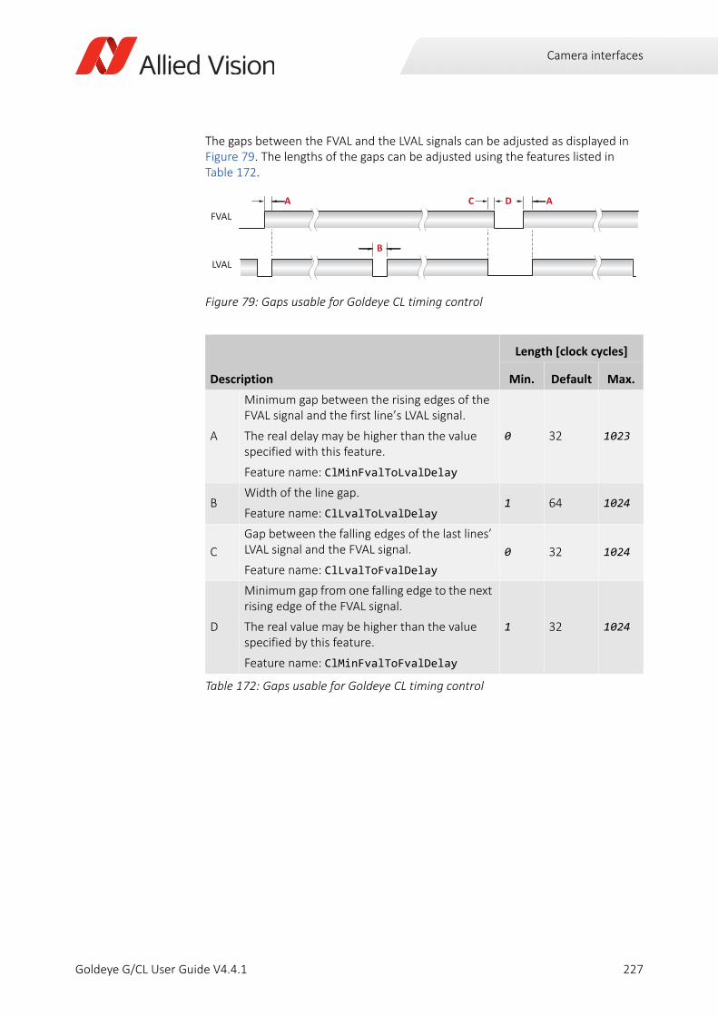
Camera interfaces
The gaps between the FVAL and the LVAL signals can be adjusted as displayed in Figure 79. The lengths of the gaps can be adjusted using the features listed in Table 172.
Figure 79: Gaps usable for Goldeye CL timing control
Description
Length [clock cycles]
Min. Default Max.
A
Minimum gap between the rising edges of the FVAL signal and the first line’s LVAL signal.
The real delay may be higher than the value specified with this feature.
Feature name: ClMinFvalToLvalDelay
0 32 1023
BWidth of the line gap.
Feature name: ClLvalToLvalDelay1 64 1024
C
Gap between the falling edges of the last lines’ LVAL signal and the FVAL signal.
Feature name: ClLvalToFvalDelay
0 32 1024
D
Minimum gap from one falling edge to the next rising edge of the FVAL signal.
The real value may be higher than the value specified by this feature.
Feature name: ClMinFvalToFvalDelay
1 32 1024
Table 172: Gaps usable for Goldeye CL timing control
FVAL
LVAL
CA
B
D A
227Goldeye G/CL User Guide V4.4.1
Camera interfaces
Starting the acquisition automatically (CL)
To start the acquisition automatically after the camera powers up, follow these steps:
Step 1: Go to the AcquisitionAutoStartMode feature and set it to On.
Step 2: Select a user set, using the UserSetSelector feature.
Step 3: Save the current camera parameters in the selected user set, using the UserSetSave feature.
Step 4: To set the selected user set as default user set that will be active after the next start of the camera, activate it using the UserSetLoad feature.
Result: Now the camera will start the acquisition automatically after the next power-up.
228Goldeye G/CL User Guide V4.4.1
Triggering
Goldeye G/CL User Guide V4.4.1
This chapter includes:
Trigger timing diagram........................................................ 230Trigger rules ........................................................................ 231
229
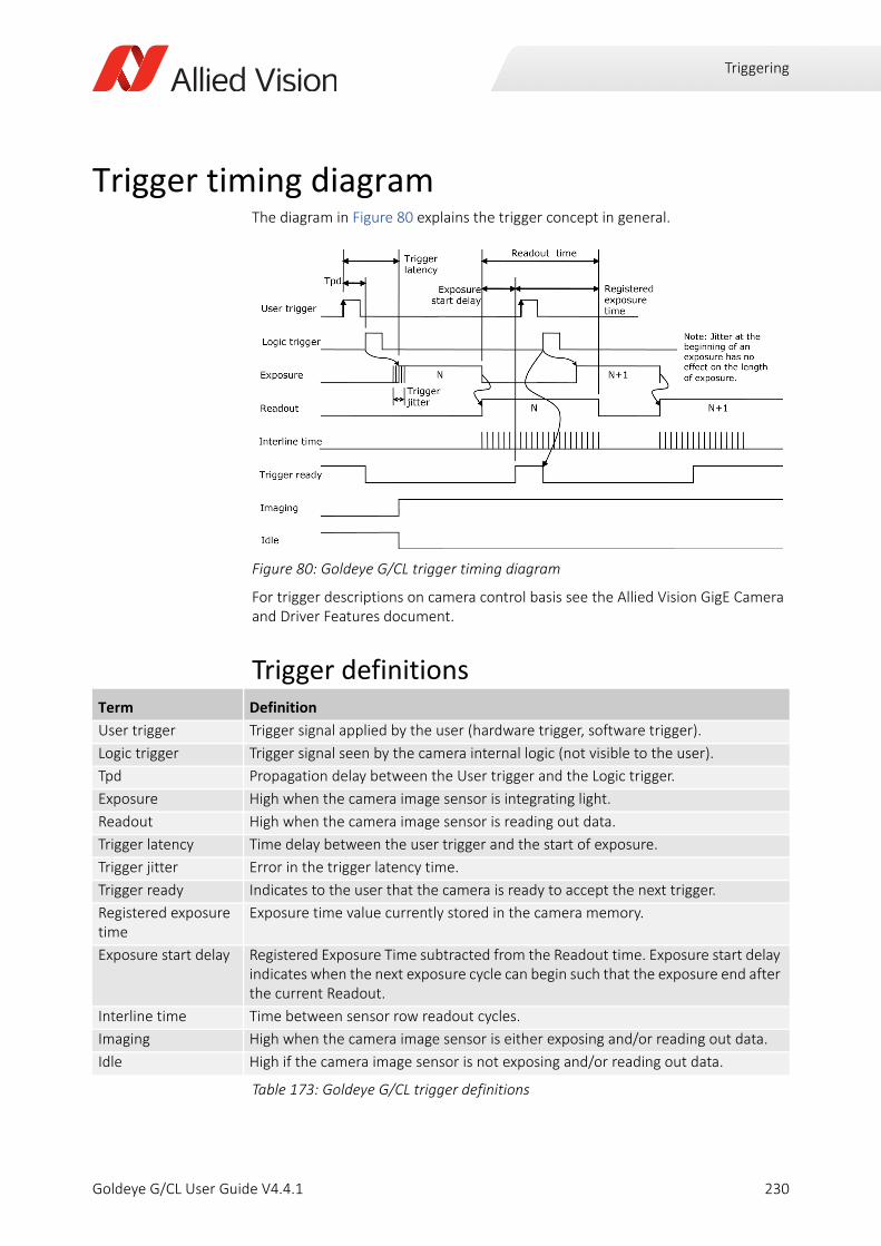
Triggering
Trigger timing diagramThe diagram in Figure 80 explains the trigger concept in general.
For trigger descriptions on camera control basis see the Allied Vision GigE Camera and Driver Features document.
Trigger definitions
Figure 80: Goldeye G/CL trigger timing diagram
Term Definition
User trigger Trigger signal applied by the user (hardware trigger, software trigger).
Logic trigger Trigger signal seen by the camera internal logic (not visible to the user).
Tpd Propagation delay between the User trigger and the Logic trigger.
Exposure High when the camera image sensor is integrating light.
Readout High when the camera image sensor is reading out data.
Trigger latency Time delay between the user trigger and the start of exposure.
Trigger jitter Error in the trigger latency time.
Trigger ready Indicates to the user that the camera is ready to accept the next trigger.
Registered exposure time
Exposure time value currently stored in the camera memory.
Exposure start delay Registered Exposure Time subtracted from the Readout time. Exposure start delay indicates when the next exposure cycle can begin such that the exposure end after the current Readout.
Interline time Time between sensor row readout cycles.
Imaging High when the camera image sensor is either exposing and/or reading out data.
Idle High if the camera image sensor is not exposing and/or reading out data.
Table 173: Goldeye G/CL trigger definitions
230Goldeye G/CL User Guide V4.4.1
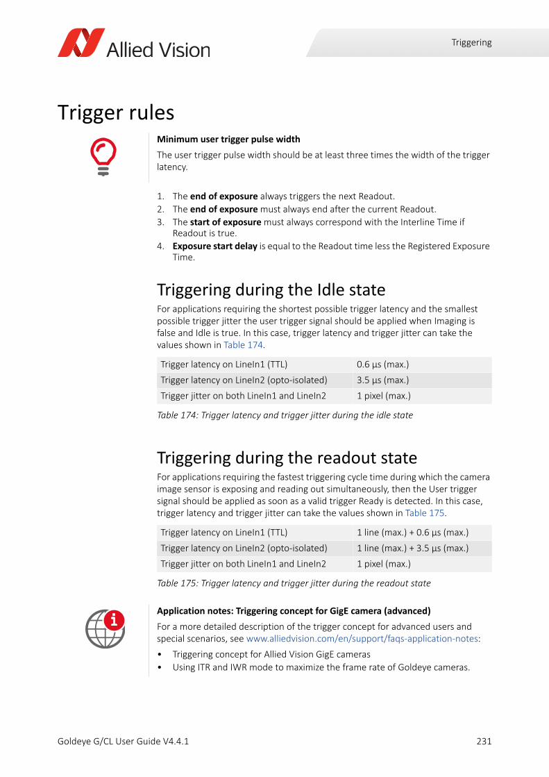
Triggering
Trigger rules
1. The end of exposure always triggers the next Readout.
2. The end of exposure must always end after the current Readout.
3. The start of exposure must always correspond with the Interline Time if Readout is true.
4. Exposure start delay is equal to the Readout time less the Registered Exposure Time.
Triggering during the Idle stateFor applications requiring the shortest possible trigger latency and the smallest possible trigger jitter the user trigger signal should be applied when Imaging is false and Idle is true. In this case, trigger latency and trigger jitter can take the values shown in Table 174.
Triggering during the readout stateFor applications requiring the fastest triggering cycle time during which the camera image sensor is exposing and reading out simultaneously, then the User trigger signal should be applied as soon as a valid trigger Ready is detected. In this case, trigger latency and trigger jitter can take the values shown in Table 175.
Minimum user trigger pulse width
The user trigger pulse width should be at least three times the width of the trigger latency.
Trigger latency on LineIn1 (TTL) 0.6 µs (max.)
Trigger latency on LineIn2 (opto-isolated) 3.5 µs (max.)
Trigger jitter on both LineIn1 and LineIn2 1 pixel (max.)
Table 174: Trigger latency and trigger jitter during the idle state
Trigger latency on LineIn1 (TTL) 1 line (max.) + 0.6 µs (max.)
Trigger latency on LineIn2 (opto-isolated) 1 line (max.) + 3.5 µs (max.)
Trigger jitter on both LineIn1 and LineIn2 1 pixel (max.)
Table 175: Trigger latency and trigger jitter during the readout state
Application notes: Triggering concept for GigE camera (advanced)
For a more detailed description of the trigger concept for advanced users and special scenarios, see www.alliedvision.com/en/support/faqs-application-notes:
• Triggering concept for Allied Vision GigE cameras
• Using ITR and IWR mode to maximize the frame rate of Goldeye cameras.
i
231Goldeye G/CL User Guide V4.4.1
Image data flow
Goldeye G/CL User Guide V4.4.1
This chapter includes:
Image data flow................................................................... 233Image corrections ............................................................... 234Image processing ................................................................ 236Automatic image control .................................................... 238Other image controls .......................................................... 245Value changes by feature interdependencies .................... 247
232

Image data flow
Image data flowThe following block diagram illustrates the flow of image data within the camera. The features of the individual modules are described in detail on the following pages.
Note that, depending on firmware version, not all of the modules and features shown in Figure 81 are available.
The Goldeye G/CL contains a chain of image processing modules, called the image processing chain. The first module (called Analog Gain) receives the source signal from the sensor. Each of the subsequent modules receives the output data of the previous module as input.
The behavior of each module is configurable by software via specific features. That way, it is possible to set parameters or operation modes for each module.
Each module passes on the data to the succeeding module. The output of the last module is stored in the frame memory, which in turn passes it on to the GigE or Camera Link interface for output.
Figure 81: Goldeye G/CL image data flow
Correc on data memory
Correc on data memory
SensorSensor frontendSensor frontend
ADCADC
Analog Analog AnalogAnalog
Black level2Black level2Gain2Gain2Sensor gain1Sensor gain1Sensor gain1
n-bit3n-bit3
Defect pixel correc on (DPC)
Defect pixel correc on (DPC)
Horizontal binningHorizontal binning
Ver cal BinningVer cal Binning
Non uniformity correc on (NUC)Non uniformity
correc on (NUC)Non uniformity
correc on (NUC)Non uniformity
correc on (NUC)n-bit3n-bit3 n-bit3n-bit3
Background correc on
+-
Background correc on
+-
n-bit3n-bit3 n-bit3n-bit3
n-bit3n-bit3
n-bit3
Camera Link interface
Camera Link interfaceGigE interfaceGigE interface
or
Camera Link interfaceGigE interface
or
Auto contrastAuto contrast
12 1212 12
Look up table (LUT)
12 12
Look up table (LUT)
n-bit3n-bit3
Frame memoryFrame memory
n-bit3n-bit3
Horizontal decima on2Horizontal
decima on2Ver cal
decima on2Ver cal
decima on2
Analog Analog
Correc on data pipeline
1 All Goldeye G/CL models, except for G/CL-030 and G/CL-1302 Goldeye G/CL-030 and G/CL-130 only3 Model dependent: See ADC bit depths in the Specifications chapter.
233Goldeye G/CL User Guide V4.4.1
Image data flow
Image correctionsThe corrections applied to the image are of special relevance within the Goldeye camera. They are applied by the following modules.
• Non-uniformity correction (NUC)
• Background correction (BC)
• Defect pixel correction (DPC)
The corrections need special correction data that must be provided prior to operating the image processing chain.
Find detailed descriptions of the features and the functionality associated with them in the Goldeye G/CL Features Reference.
Determination and storage of correction dataFor each individual camera, specific correction data is determined during the manufacturing process. All necessary correction data is stored within the camera‘s non-volatile flash memory ex works.
During camera start-up, the available correction data is copied from the flash memory onto the correction data memory for real time access.
From the correction data memory, the correction data is transferred to the individual correction modules. The correction data transfer is synchronized with the transfer of image data from the sensor. A correction module may also write back to the correction data memory, depending on its functionality.
The IR specific image correction modules are described in detail in the following sections.
Non-uniformity correctionEvery pixel of an InGaAs sensor possesses its individual amount of dark signal (dark signal non-uniformity, DSNU) and an individual sensitivity for light (photo response non-uniformity, PRNU). Thus, while exposing, each sensor creates a specific, non-uniform underlying pattern. This pattern can be compensated with help of the non-uniformity correction.
To correct the non-uniformity, correction values for gain and offset of each pixel are determined based on multiple reference images and applied to the actual image. Ideally, after correction no image structure is recognizable.
However, there are various conditions that influence the image quality:
• Analog gain setting
• Sensor temperature
• Exposure time
234Goldeye G/CL User Guide V4.4.1
Image data flow
These conditions need corresponding correction data for best correction quality. Thus, the camera contains several data sets for a range of conditions.
Because each correction data set is applicable under certain conditions only, the relevant conditions are stored with the data set.
An automated data set selection feature keeps track of the conditions. If any of the parameters changes, the most suitable correction data set is selected automatically. No additional user interaction is necessary.
Set to Continuous, this function updates the data set selection for every frame.
Background correctionThe background correction is used as an additional correction, based on actual operating conditions, to optimize the result of the NUC.
The correction data for the NUC is factory-provided and based on specific conditions: exposure time, sensor temperature, and sensor gain setting. If the conditions during camera operation are different, non-uniformity correction does not work at best performance.
To compensate for remaining non-uniformity, the live image is corrected with a previously recorded dark image. This image is subtracted from the pre-corrected image to reduce the fixed pattern noise.
To adapt the BC to local conditions, customers acquire their own volatile correction image. It is also possible to shift the offset individually, if needed.
Defect pixel correctionThe pixels of InGaAs sensors may show abnormal behavior in one or more of the three characteristics:
• Dark offset
• Photo response
• Dynamic noise
The result is an excessively reduced dynamic range. These pixels are counted as defect pixels.
The value of each defect pixel is replaced by an interpolated value from non-defect neighboring pixels. This way, the image appears without disturbing bright or dark pixels.
235Goldeye G/CL User Guide V4.4.1
Image data flow
Image processing
Black levelBlackLevel is available only on Goldeye G/CL-030 and G/CL-130. BlackLevel controls the DC offset applied to the video signal.
GainGoldeye cameras use two different concepts to control the gain level.
Look-up tableThe use of a look-up table allows any mapping function in the form output = f(input) to be applied to the pixel values at runtime.
The factory setting of Goldeye cameras includes eight preloaded LUT files.
• Four pre-configured LUT files are available. Those files are 14-bit LSB aligned and are named from LUT_000 to LUT_003. The pre-configured files are not changeable in user mode.
• Four user-configurable LUT files are available. Those files are empty and are named from LUT_User_000 to LUT_User_003.
Loading a dataset files into the volatile LUT memory1. Select the file to be loaded with LUTDatasetSelector
2. Select the target LUT with LUTSelector
3. Call the command LUTDatasetLoad
The LUT will not be loaded if an empty dataset file has been selected.
To avoid temporary invalid image data, we recommend you to do one of the following before executing LUTDatasetLoad:
• Stop image acquisition
• Set LUTEnable to False.
Feature descriptions
For detailed features descriptions, see the Goldeye G/CL Features Reference at www.alliedvision.com/en/support/technical-documentation/goldeye-gcl-documentation.
Feature Location Available values Unit Supported models
Gain Camera electronics 0 to 18 dB (float) Dezibel Goldeye G/CL-030, G/CL-130
SensorGain Sensor 1 or 2 gain steps Factor All other Goldeye models
Table 176:
i
236Goldeye G/CL User Guide V4.4.1
Image data flow
Saving a LUT from volatile memory to file1. Select the LUT to be saved with LUTSelector
2. Select the target file with LUTDatasetSelector
3. Call the command LUTDatasetSave.
To avoid temporary invalid image data, we recommend you to do one of the following before changing the LUTValue at several index positions of a LUT:
• Stop image acquisition
• Set LUTEnable to False.
BinningBinning reduces the image resolution by merging the gray values of adjacent pixels, but based on the full ROI.
Different binning modes:
• Sum increases the sensitivity.
• Average can be used to reduce noise.
In all Goldeye cameras, digital binning is applied after the Background Correction. Background Correction can be used to reduce the background level to enable higher binning values.
DecimationDecimation reduces the image resolution by omitting pixels, but based on the full ROI.
Different decimation modes:
• Discard ignores the pixel values of omitted pixels.
• Average can be used to reduce noise.
In all Goldeye cameras, decimation is applied after binning.
237Goldeye G/CL User Guide V4.4.1
Image data flow
Automatic image control
DefinitionsTo properly explain the working principle of automatic image control, the definition of several special terms is clarified first. Refer also to Figure 82 on page 239.
Accounted pixelsOnce the outliers are discarded from the calculation, all pixels holding gray values in the middle of the image histogram constitute the Accounted pixels.
Mean valueThe average gray value of all accounted pixels. This means that within the accounted pixels range of the image histogram, the same number of accounted pixels is situated to either side of the mean value.
Minimum and maximumThe smallest and the largest gray value of pixels accepted within the number of accounted pixels.
OutliersOutliers are defined as the brightest and darkest pixels in an image. Usually they originate from defect pixels of the sensor itself.
Small, very bright, or very dark objects in the observed scene can also create outliers. Because very small objects usually do not carry much useful scene information, they can be treated like outliers as well.
In an image histogram, the outliers show on the far-left side (dark pixels) and on the far-right side (bright pixels).
Eliminating outliersThe calculations of all auto level control features, including the automatic exposure operation, may be influenced by outliers in an unwanted way.
The auto level control settings allow for discarding outliers and thus preventing their undesired impact on the auto level control adjustments.
• To exclude the outliers on the dark side of the histogram (left), use the AutoModeOutliersDark feature. To include all dark pixels into the calculations, set the feature to 0.
238Goldeye G/CL User Guide V4.4.1
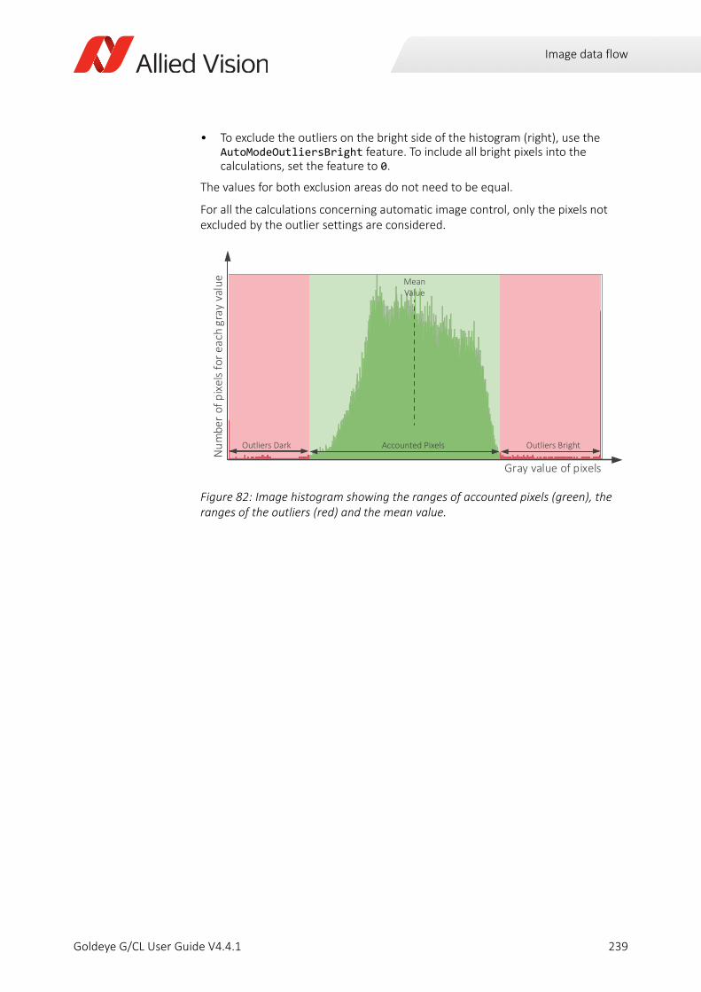
Image data flow
• To exclude the outliers on the bright side of the histogram (right), use the AutoModeOutliersBright feature. To include all bright pixels into the calculations, set the feature to 0.
The values for both exclusion areas do not need to be equal.
For all the calculations concerning automatic image control, only the pixels not excluded by the outlier settings are considered.
Figure 82: Image histogram showing the ranges of accounted pixels (green), the ranges of the outliers (red) and the mean value.
Gray value of pixels
Num
ber
of p
ixel
s fo
r eac
h gr
ay v
alue
Accounted Pixels Outliers BrightOutliers Dark
MeanValue
239Goldeye G/CL User Guide V4.4.1
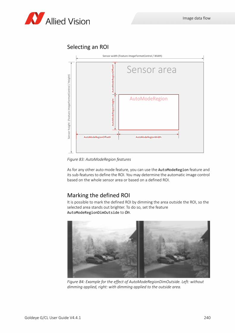
Image data flow
Selecting an ROI
As for any other auto mode feature, you can use the AutoModeRegion feature and its sub-features to define the ROI. You may determine the automatic image control based on the whole sensor area or based on a defined ROI.
Marking the defined ROIIt is possible to mark the defined ROI by dimming the area outside the ROI, so the selected area stands out brighter. To do so, set the feature AutoModeRegionDimOutside to On.
Figure 83: AutoModeRegion features
Figure 84: Example for the effect of AutoModeRegionDimOutside. Left: without dimming applied, right: with dimming applied to the outside area.
Sensor areaSensor width (Feature ImageFormatControl / Width)
Sens
or h
eigh
t (F
eatu
re Im
ageF
orm
atCo
ntro
l / H
eigh
t)
AutoModeRegion
AutoModeRegionO setX AutoModeRegionWidth
Auto
Mod
eReg
ionH
eigh
tAu
toM
odeR
egio
nOse
tY
240Goldeye G/CL User Guide V4.4.1
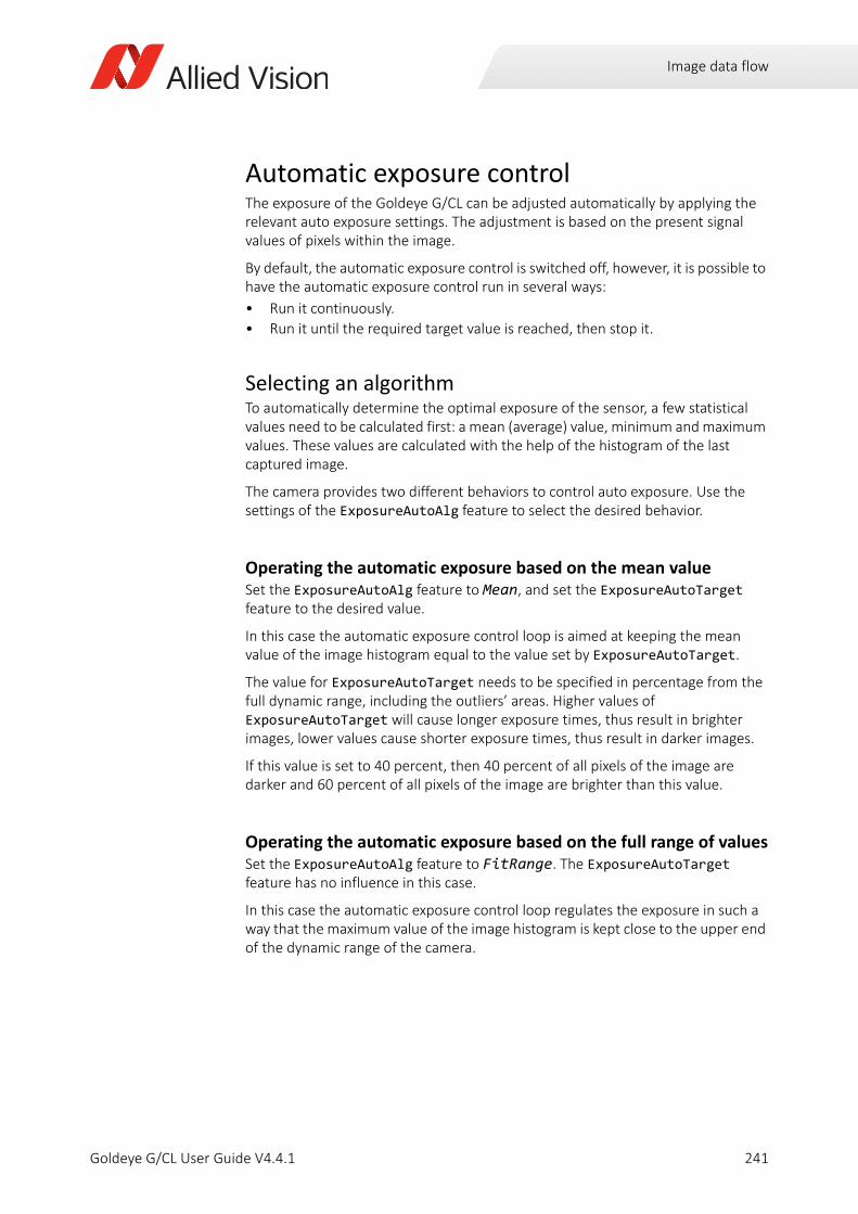
Image data flow
Automatic exposure controlThe exposure of the Goldeye G/CL can be adjusted automatically by applying the relevant auto exposure settings. The adjustment is based on the present signal values of pixels within the image.
By default, the automatic exposure control is switched off, however, it is possible to have the automatic exposure control run in several ways:
• Run it continuously.
• Run it until the required target value is reached, then stop it.
Selecting an algorithmTo automatically determine the optimal exposure of the sensor, a few statistical values need to be calculated first: a mean (average) value, minimum and maximum values. These values are calculated with the help of the histogram of the last captured image.
The camera provides two different behaviors to control auto exposure. Use the settings of the ExposureAutoAlg feature to select the desired behavior.
Operating the automatic exposure based on the mean valueSet the ExposureAutoAlg feature to Mean, and set the ExposureAutoTarget feature to the desired value.
In this case the automatic exposure control loop is aimed at keeping the mean value of the image histogram equal to the value set by ExposureAutoTarget.
The value for ExposureAutoTarget needs to be specified in percentage from the full dynamic range, including the outliers’ areas. Higher values of ExposureAutoTarget will cause longer exposure times, thus result in brighter images, lower values cause shorter exposure times, thus result in darker images.
If this value is set to 40 percent, then 40 percent of all pixels of the image are darker and 60 percent of all pixels of the image are brighter than this value.
Operating the automatic exposure based on the full range of valuesSet the ExposureAutoAlg feature to FitRange. The ExposureAutoTarget feature has no influence in this case.
In this case the automatic exposure control loop regulates the exposure in such a way that the maximum value of the image histogram is kept close to the upper end of the dynamic range of the camera.
241Goldeye G/CL User Guide V4.4.1
Image data flow
ToleranceIf the automatic exposure is calculated for every frame (ExposureAuto = Continuous), most likely there are minuscule adjustments to be applied to each frame. These adjustments may cause certain, though usually insignificant, variations of the image brightness between consecutive frames.
To prevent these adjustments, the feature ExposureAutoAdjustTol can be used.
The exposure is adjusted only if the current regulated value deviates from the ideal target value by more than a given percentage.
Slowing down the auto exposure adjustmentsBy default, the automatic exposure adjustments run at 20% speed1. Using the ExposureAutoRate feature, you can increase or decrease the automatic exposure adjustments to a fraction of the maximum possible speed. This can be useful for some applications and sensor settings, to prevent the auto exposure control loop from occurring oscillations.
120% as default applies from firmware V02.22.X. Previous versions have this parameter set to 100%.
242Goldeye G/CL User Guide V4.4.1
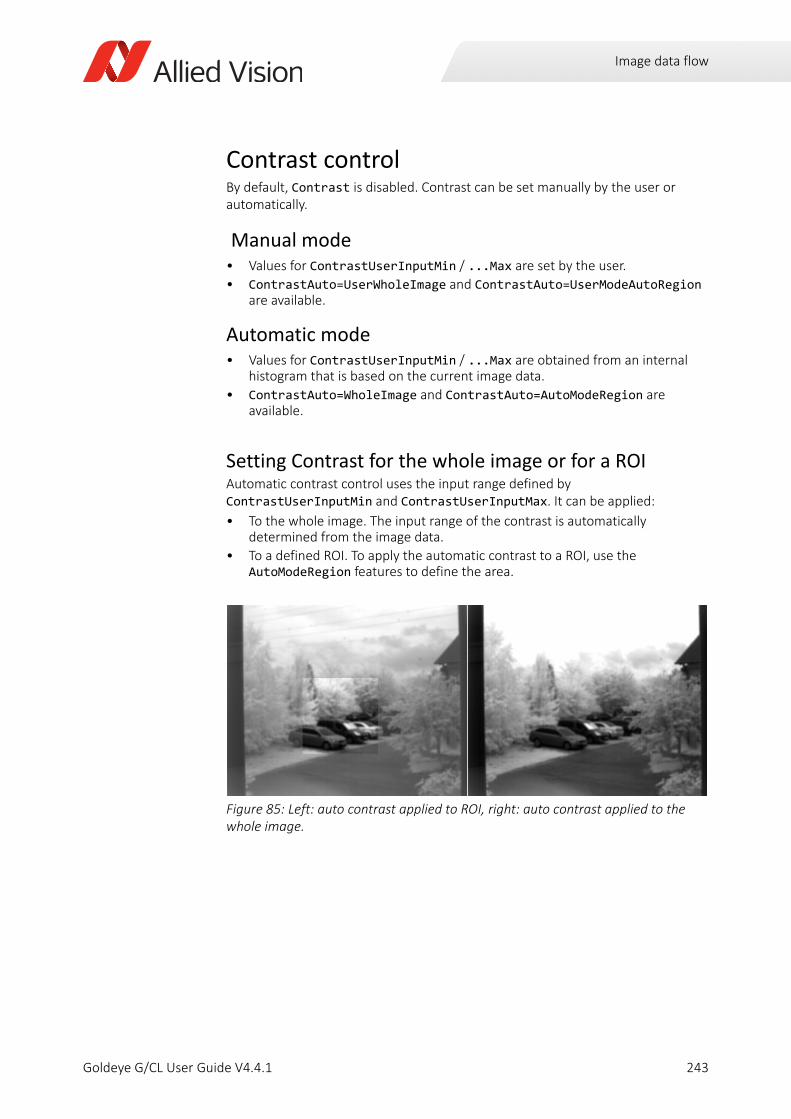
Image data flow
Contrast controlBy default, Contrast is disabled. Contrast can be set manually by the user or automatically.
Manual mode• Values for ContrastUserInputMin / ...Max are set by the user.
• ContrastAuto=UserWholeImage and ContrastAuto=UserModeAutoRegion are available.
Automatic mode• Values for ContrastUserInputMin / ...Max are obtained from an internal
histogram that is based on the current image data.
• ContrastAuto=WholeImage and ContrastAuto=AutoModeRegion are available.
Setting Contrast for the whole image or for a ROIAutomatic contrast control uses the input range defined by ContrastUserInputMin and ContrastUserInputMax. It can be applied:
• To the whole image. The input range of the contrast is automatically determined from the image data.
• To a defined ROI. To apply the automatic contrast to a ROI, use the AutoModeRegion features to define the area.
Figure 85: Left: auto contrast applied to ROI, right: auto contrast applied to the whole image.
243Goldeye G/CL User Guide V4.4.1
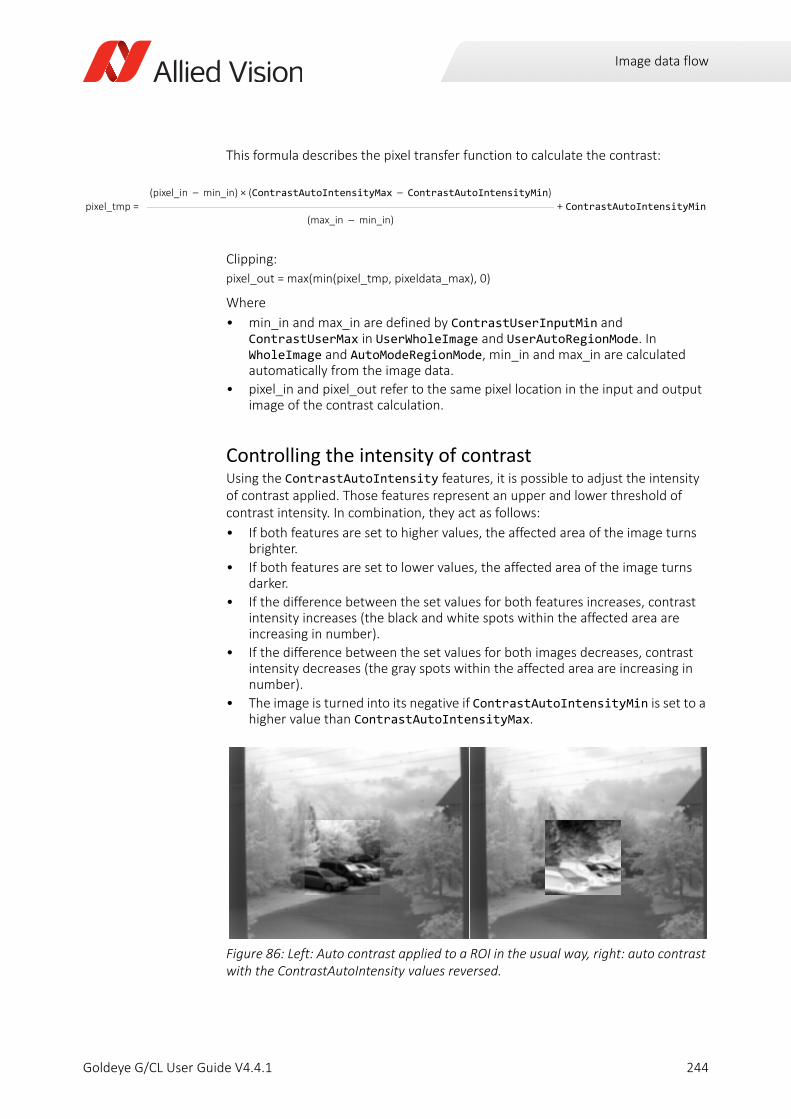
Image data flow
This formula describes the pixel transfer function to calculate the contrast:
Clipping:
pixel_out = max(min(pixel_tmp, pixeldata_max), 0)
Where
• min_in and max_in are defined by ContrastUserInputMin and ContrastUserMax in UserWholeImage and UserAutoRegionMode. In WholeImage and AutoModeRegionMode, min_in and max_in are calculated automatically from the image data.
• pixel_in and pixel_out refer to the same pixel location in the input and output image of the contrast calculation.
Controlling the intensity of contrastUsing the ContrastAutoIntensity features, it is possible to adjust the intensity of contrast applied. Those features represent an upper and lower threshold of contrast intensity. In combination, they act as follows:
• If both features are set to higher values, the affected area of the image turns brighter.
• If both features are set to lower values, the affected area of the image turns darker.
• If the difference between the set values for both features increases, contrast intensity increases (the black and white spots within the affected area are increasing in number).
• If the difference between the set values for both images decreases, contrast intensity decreases (the gray spots within the affected area are increasing in number).
• The image is turned into its negative if ContrastAutoIntensityMin is set to a higher value than ContrastAutoIntensityMax.
pixel_tmp = (pixel_in – min_in) × (ContrastAutoIntensityMax – ContrastAutoIntensityMin)
+ ContrastAutoIntensityMin(max_in – min_in)
Figure 86: Left: Auto contrast applied to a ROI in the usual way, right: auto contrast with the ContrastAutoIntensity values reversed.
244Goldeye G/CL User Guide V4.4.1
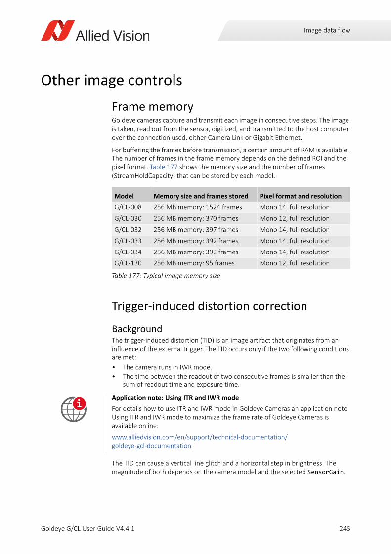
Image data flow
Other image controls
Frame memoryGoldeye cameras capture and transmit each image in consecutive steps. The image is taken, read out from the sensor, digitized, and transmitted to the host computer over the connection used, either Camera Link or Gigabit Ethernet.
For buffering the frames before transmission, a certain amount of RAM is available. The number of frames in the frame memory depends on the defined ROI and the pixel format. Table 177 shows the memory size and the number of frames (StreamHoldCapacity) that can be stored by each model.
Trigger-induced distortion correction
BackgroundThe trigger-induced distortion (TID) is an image artifact that originates from an influence of the external trigger. The TID occurs only if the two following conditions are met:
• The camera runs in IWR mode.
• The time between the readout of two consecutive frames is smaller than the sum of readout time and exposure time.
The TID can cause a vertical line glitch and a horizontal step in brightness. The magnitude of both depends on the camera model and the selected SensorGain.
Model Memory size and frames stored Pixel format and resolution
G/CL-008 256 MB memory: 1524 frames Mono 14, full resolution
G/CL-030 256 MB memory: 370 frames Mono 12, full resolution
G/CL-032 256 MB memory: 397 frames Mono 14, full resolution
G/CL-033 256 MB memory: 392 frames Mono 14, full resolution
G/CL-034 256 MB memory: 392 frames Mono 14, full resolution
G/CL-130 256 MB memory: 95 frames Mono 12, full resolution
Table 177: Typical image memory size
Application note: Using ITR and IWR mode
For details how to use ITR and IWR mode in Goldeye Cameras an application note Using ITR and IWR mode to maximize the frame rate of Goldeye Cameras is available online:
www.alliedvision.com/en/support/technical-documentation/goldeye-gcl-documentation
i
245Goldeye G/CL User Guide V4.4.1
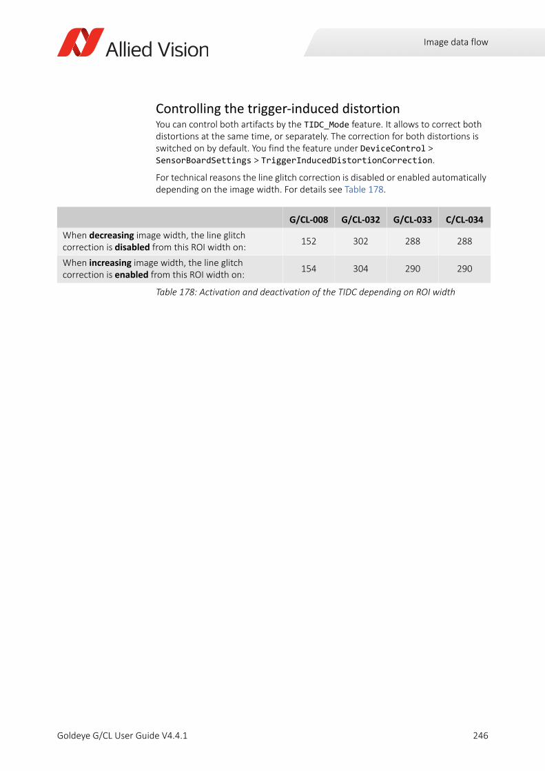
Image data flow
Controlling the trigger-induced distortionYou can control both artifacts by the TIDC_Mode feature. It allows to correct both distortions at the same time, or separately. The correction for both distortions is switched on by default. You find the feature under DeviceControl > SensorBoardSettings > TriggerInducedDistortionCorrection.
For technical reasons the line glitch correction is disabled or enabled automatically depending on the image width. For details see Table 178.
G/CL-008 G/CL-032 G/CL-033 C/CL-034
When decreasing image width, the line glitch correction is disabled from this ROI width on:
152 302 288 288
When increasing image width, the line glitch correction is enabled from this ROI width on:
154 304 290 290
Table 178: Activation and deactivation of the TIDC depending on ROI width
246Goldeye G/CL User Guide V4.4.1
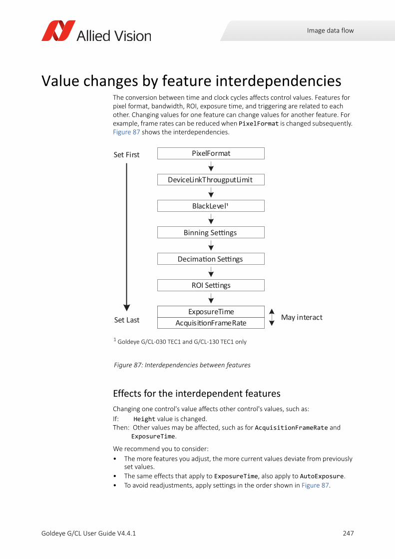
Image data flow
Value changes by feature interdependencies The conversion between time and clock cycles affects control values. Features for pixel format, bandwidth, ROI, exposure time, and triggering are related to each other. Changing values for one feature can change values for another feature. For example, frame rates can be reduced when PixelFormat is changed subsequently. Figure 87 shows the interdependencies.
Effects for the interdependent features
Changing one control's value affects other control's values, such as:
If: Height value is changed.Then: Other values may be affected, such as for AcquisitionFrameRate and
ExposureTime.
We recommend you to consider:
• The more features you adjust, the more current values deviate from previously set values.
• The same effects that apply to ExposureTime, also apply to AutoExposure.
• To avoid readjustments, apply settings in the order shown in Figure 87.
Figure 87: Interdependencies between features
Set First
Set Last
PixelFormat
DeviceLinkThrougputLimit
ROI Se ngs
Se ngs
BlackLevel
May interactAcquisi onFrameRate
ExposureTimeAcquisi onFrameRate
ExposureTime
1 Goldeye G/CL-030 TEC1 and G/CL-130 TEC1 only
247Goldeye G/CL User Guide V4.4.1
Temperature control
Goldeye G/CL User Guide V4.4.1
This chapter includes:
Influence of temperature on the sensor ............................ 249Control of the sensor temperature..................................... 250Neutralization of the temperature influence ..................... 253
248
Temperature control
Influence of temperature on the sensorDuring operation, power consumed and dissipated by the internal electronic components causes the interior and case of the camera to heat up.
The InGaAs sensor is affected by temperature in two ways:
1. Absolute level of sensor temperature
An increase in sensor temperature has a negative impact on the image quality of the InGaAs sensor (FPA), for several reasons.
- An increased sensor temperature increases the dark current of the FPA’s photo-diodes, thus decreasing the dynamic range of the camera. As a rule of thumb, a temperature increase of 8 Kelvin doubles the dark current. The dark current produces additional offset and noise, especially at longer exposure times, which causes a decrease in image contrast.
- The spectral sensitivity may change: a difference in temperature may cause the sensitivity curve to drift or to become slightly narrower.
- Certain components of the InGaAs sensor are prone to temperature drift. A drop in temperature causes a shift of the spectral sensitivity of 25 nanometers toward the lower wavelengths.
2. Fluctuation of sensor temperature
If the temperature influence on the sensor remains constant, this ensures constantly high image quality. To achieve this, the temperature of the sensor is stabilized at one of several defined setpoints.
For the Goldeye stabilized and cooled models, three or four setpoints are defined, depending on the camera model.
To ensure a consistently optimum image quality, the influence of temperature change needs to be minimized. Two measures are taken to achieve this:
• Temperature control of the sensor,
• Neutralization of the temperature influence.
The ways of temperature control that are realized with Goldeye cameras are described in detail in this chapter.
CAUTION
Risk of burns
The camera housing may heat up during operation. Touching the camera with bare hands may lead to injuries.
Wear protective gloves when touching a heated-up camera during operation. Also, use proper heat dissipation methods to keep the camera as cool as possible.
249Goldeye G/CL User Guide V4.4.1
Temperature control
Control of the sensor temperature
Warm-up periodAfter switching on the camera, the TEC stabilizes the sensor temperature at the default setpoint, if possible. Except for TECless models, optimal image quality is reached within one minute.
Goldeye G/CL-008, G/CL-030, and G/CL-130 models are also able to heat up the sensor to any temperature within the operating temperature range.
A red flashing temperature status LED indicates the warm-up period. A steady green temperature status LED indicates the Stable temperature state.
Temperature stabilization and active coolingTemperature-stabilized Goldeye models are equipped with a single-stage thermo-electric cooling (TEC1) to keep the sensor at a stable temperature that is as low as possible. The specially designed Goldeye housing dissipates the heat build-up inside the camera and radiates the heat into the environment
The dual-stage thermo-electric cooling (TEC2) allows you to operate the sensor at a temperature well below ambient temperature. This allows for keeping a higher image quality even with longer exposure times. However, with low sensor temperatures and a larger difference to ambient temperatures, condensation on the sensor is likely to occur. To avoid condensation, every TEC2-cooled sensor is placed inside a nitrogen-filled chamber.
In addition to temperature stabilization, Goldeye Cool cameras are equipped with a fan to actively dissipate the heat that builds up internally. Note that the housing size design is independent from the implemented thermo-electric cooling. A Cool model does not necessarily have a two-stage TEC.
See Neutralization of the temperature influence on page 253 for a detailed explanation.
Use a heat sink to reduce camera temperature
To improve the cooling capability of the Goldeye stabilized and TECless models, a heat sink set is available that can be mounted to the camera by the customer. Up to four heat sinks can be fitted to one camera.
The heat sink set is available from Allied Vision, product code 1068300.
Application note: Usage of Heat Sinks with Goldeye Cameras
This application note explains the handling of heat sinks with Goldeye cameras and lists additional methods to improve camera cooling:
www.alliedvision.com/en/support/technical-documentation/goldeye-gcl-documentation
i
250Goldeye G/CL User Guide V4.4.1
Temperature control
Passive camera coolingGoldeye TECless models provide no active temperature stabilization for the sensor. These models are especially suitable for environments with a low and stable ambient temperature, or in application scenarios where the influence of temperature on image quality is limited, for example at low exposure times of less than 10 milliseconds.
Recommended environment for Goldeye TEClessGoldeye TECless models are not equipped with a TEC element, hence the camera does not possess temperature setpoints and cannot stabilize the sensor temperature. Therefore, TECless models are recommended to be run in an environment with stable temperature and humidity.
Their non-uniformity correction sets are calibrated for a sensor temperature of +45 degrees Celsius, because this is the sensor temperature that most likely is to be expected when the camera is operated at an ambient temperature of 23 degrees Celsius and a relative humidity of 40 percent.
Additional heating for G/CL-008, G/CL-x30The TEC1 element of a camera usually can only cool the sensor. In addition to that, Goldeye G/CL-008, G/CL-030, and G/CL-130 models use the TEC1 element to heat the sensor. This ability has the following advantages:
• The camera can operate at a sensor temperature that is higher than the ambient or case temperature.
• When used for low-temperature applications, if the ambient temperature is far below +20 degrees Celsius, or if the default temperature setpoint has been set high above the ambient temperature, the warm-up period is considerably shortened. Even in ambient temperatures below 0 degrees Celsius, the camera reaches a stable temperature within one minute.
• The heating capability prevents any variation of the sensitivity curve caused by fluctuation of temperature.
Activating the heating of Goldeye G modelsAfter activating the heating of Goldeye G-008, G-030, and G-130, switching down to a setpoint below the selected setpoint is disabled. The ability to switch to a higher setpoint depends on the SensorTemperatureSetpointMode feature:
• If set to Auto, the camera is able to switch to a higher setpoint, if it exists.
• If set to Manual, the camera is not able to switch to any other setpoint.
To activate the heating of the camera, follow these steps:
Step 1: Set the SensorTemperatureTargetSetpoint feature to the desired target setpoint.
Step 2: Set the SensorTemperatureControlMode feature to TemperatureControlTarget.
251Goldeye G/CL User Guide V4.4.1
Temperature control
Activating the heating of the CL modelsAfter activating the heating of Goldeye CL-008, CL-030, and CL-130, switching down to a setpoint below the selected setpoint is disabled. The ability to switch to a higher setpoint, depends on the RegSensorTemperatureSetpointMode register:
• If set to Auto, the camera is able to switch to a higher setpoint, if it exists.
• If set to Manual, the camera is not able to switch to any other setpoint.
To activate the heating of the camera, follow these steps:
Step 1: Set the RegSensorTemperatureTargetSetpoint register to the desired target setpoint.
Step 2: Set the RegSensorTemperatureControlMode register to TemperatureControlTarget.
Reduce power consumption of the camera
Reducing the camera‘s operating temperature can reduce its typical power consumption significantly for any given temperature setpoint.
The TEC works more efficiently if the temperature difference between the cool side and the warm side of the TEC is decreased.
Goldeye Cool variants: Do not cover the fan outlet
Always ensure that a free flow of air from the fan outlet on the camera top is possible.
Obstructing the air flow may result in an unexpected shutdown of the camera.
252Goldeye G/CL User Guide V4.4.1
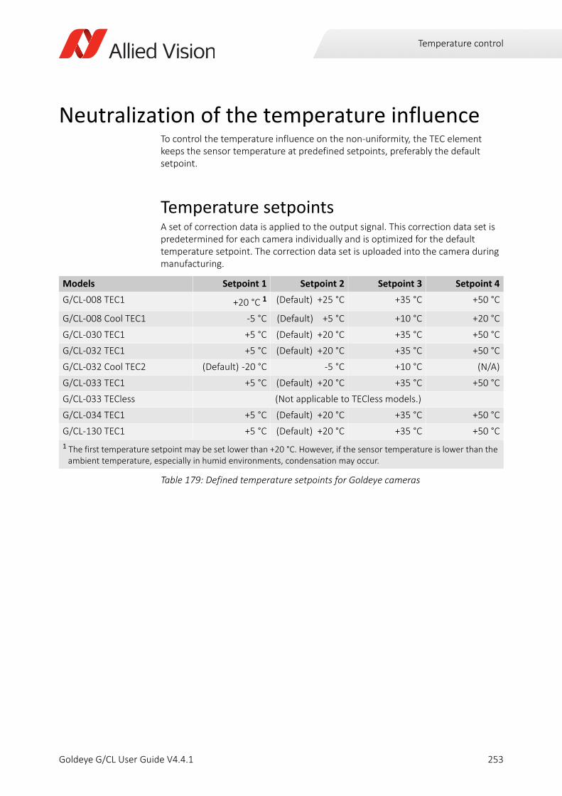
Temperature control
Neutralization of the temperature influenceTo control the temperature influence on the non-uniformity, the TEC element keeps the sensor temperature at predefined setpoints, preferably the default setpoint.
Temperature setpointsA set of correction data is applied to the output signal. This correction data set is predetermined for each camera individually and is optimized for the default temperature setpoint. The correction data set is uploaded into the camera during manufacturing.
Models Setpoint 1 Setpoint 2 Setpoint 3 Setpoint 4
G/CL-008 TEC1 +20 °C 1 (Default) +25 °C +35 °C +50 °C
G/CL-008 Cool TEC1 -5 °C (Default) +5 °C +10 °C +20 °C
G/CL-030 TEC1 +5 °C (Default) +20 °C +35 °C +50 °C
G/CL-032 TEC1 +5 °C (Default) +20 °C +35 °C +50 °C
G/CL-032 Cool TEC2 (Default) -20 °C -5 °C +10 °C (N/A)
G/CL-033 TEC1 +5 °C (Default) +20 °C +35 °C +50 °C
G/CL-033 TECless (Not applicable to TECless models.)
G/CL-034 TEC1 +5 °C (Default) +20 °C +35 °C +50 °C
G/CL-130 TEC1 +5 °C (Default) +20 °C +35 °C +50 °C
1 The first temperature setpoint may be set lower than +20 °C. However, if the sensor temperature is lower than the ambient temperature, especially in humid environments, condensation may occur.
Table 179: Defined temperature setpoints for Goldeye cameras
253Goldeye G/CL User Guide V4.4.1
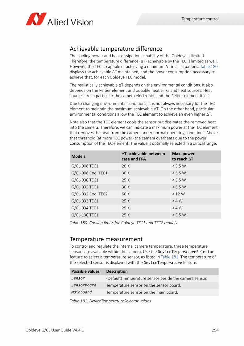
Temperature control
Achievable temperature differenceThe cooling power and heat dissipation capability of the Goldeye is limited. Therefore, the temperature difference (ΔT) achievable by the TEC is limited as well. However, the TEC is capable of achieving a minimum ΔT in all situations. Table 180 displays the achievable ΔT maintained, and the power consumption necessary to achieve that, for each Goldeye TEC model.
The realistically achievable ΔT depends on the environmental conditions. It also depends on the Peltier element and possible heat sinks and heat sources. Heat sources are in particular the camera electronics and the Peltier element itself.
Due to changing environmental conditions, it is not always necessary for the TEC element to maintain the maximum achievable ΔT. On the other hand, particular environmental conditions allow the TEC element to achieve an even higher ΔT.
Note also that the TEC element cools the sensor but dissipates the removed heat into the camera. Therefore, we can indicate a maximum power at the TEC element that removes the heat from the camera under normal operating conditions. Above that threshold (at more TEC power) the camera overheats due to the power consumption of the TEC element. The value is optimally selected in a critical range.
Temperature measurementTo control and regulate the internal camera temperature, three temperature sensors are available within the camera. Use the DeviceTemperatureSelector feature to select a temperature sensor, as listed in Table 181. The temperature of the selected sensor is displayed with the DeviceTemperature feature.
ModelsΔT achievable betweencase and FPA
Max. powerto reach ΔT
G/CL-008 TEC1 20 K < 5.5 W
G/CL-008 Cool TEC1 30 K < 5.5 W
G/CL-030 TEC1 25 K < 5.5 W
G/CL-032 TEC1 30 K < 5.5 W
G/CL-032 Cool TEC2 60 K < 12 W
G/CL-033 TEC1 25 K < 4 W
G/CL-034 TEC1 25 K < 4 W
G/CL-130 TEC1 25 K < 5.5 W
Table 180: Cooling limits for Goldeye TEC1 and TEC2 models
Possible values Description
Sensor (Default) Temperature sensor beside the camera sensor.
Sensorboard Temperature sensor on the sensor board.
Mainboard Temperature sensor on the main board.
Table 181: DeviceTemperatureSelector values
254Goldeye G/CL User Guide V4.4.1
Temperature control
Switching temperature setpoints
The Goldeye temperature control allows to switch between setpoints manually or automatically. If set to Auto, the TEC switches up or down to the next setpoint, based on the temperature inside the camera. Note that the TEC does not switch up or down immediately after the next setpoint is reached. The switch only takes place when the temperature has exceeded the setpoint by a few degrees.
TECless models do not switch setpoints.
Switching to the higher setpointAfter powering up the camera, at first the camera temperature rises. This is due to heat generation inside the camera, and possibly caused by warm ambient temperature. To keep the sensor temperature constant, the TEC keeps it at a predefined temperature setpoint (see Table 179 on page 253).
The TEC keeps the sensor temperature as long as the difference between sensor temperature and case temperature does not exceed the predefined ΔT (see Table 180 on page 254).
If the case temperature keeps rising, the difference between sensor- and case temperature exceeds the predefined ΔT. The temperature control is no longer able to keep the sensor temperature at the current setpoint. The TEC switches up to the next higher setpoint. The existing NUC data, that is optimized for the default setpoint conditions, is still applied at other setpoints.
ExampleThe Peltier element of the Goldeye G-033 and CL-033 TEC1 can achieve a ΔT of 25 kelvin. Its default temperature setpoint is set to +20 degrees Celsius.
If the camera is switched on at an ambient temperature of +8 degrees Celsius, the TEC cannot cool down the sensor to the default setpoint, because the ambient temperature is below the default setpoint. Thus, the TEC cools down the sensor to setpoint 1, which is at +5 degrees Celsius. (See Figure 88 for an illustration of this
Only the sensor board is switched off
• If the internal temperature exceeds the Alert limit, only the sensor and the cooling is shut down.
• The camera is not powered down.
• You may bring back the camera to normal operation after it is cooled down
sufficiently.
• To do so, switch the power supply off and switch it on again.
255Goldeye G/CL User Guide V4.4.1
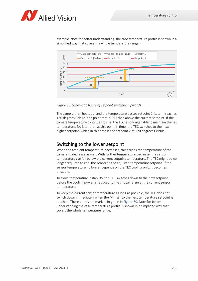
Temperature control
example. Note for better understanding: the case temperature profile is shown in a simplified way that covers the whole temperature range.)
The camera then heats up, and the temperature passes setpoint 2. Later it reaches +30 degrees Celsius, the point that is 25 kelvin above the current setpoint. If the camera temperature continues to rise, the TEC is no longer able to maintain the set temperature. No later than at this point in time, the TEC switches to the next higher setpoint, which in this case is the setpoint 2 at +20 degrees Celsius.
Switching to the lower setpointWhen the ambient temperature decreases, this causes the temperature of the camera to decrease as well. With further temperature decrease, the sensor temperature can fall below the current setpoint temperature. The TEC might be no longer required to cool the sensor to the adjusted temperature setpoint. If the sensor temperature no longer depends on the TEC cooling only, it becomes unstable.
To avoid temperature instability, the TEC switches down to the next setpoint, before the cooling power is reduced to the critical range at the current sensor temperature.
To keep the current sensor temperature as long as possible, the TEC does not switch down immediately when the Min. ΔT to the next temperature setpoint is reached. These points are marked in green in Figure 89. Note for better understanding the case temperature profile is shown in a simplified way that covers the whole temperature range.
Figure 88: Schematic figure of setpoint switching upwards
256Goldeye G/CL User Guide V4.4.1
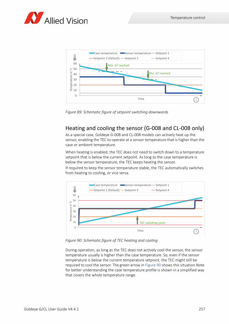
Temperature control
Heating and cooling the sensor (G-008 and CL-008 only)As a special case, Goldeye G-008 and CL-008 models can actively heat up the sensor, enabling the TEC to operate at a sensor temperature that is higher than the case or ambient temperature.
When heating is enabled, the TEC does not need to switch down to a temperature setpoint that is below the current setpoint. As long as the case temperature is below the sensor temperature, the TEC keeps heating the sensor.
If required to keep the sensor temperature stable, the TEC automatically switches from heating to cooling, or vice versa.
During operation, as long as the TEC does not actively cool the sensor, the sensor temperature usually is higher than the case temperature. So, even if the sensor temperature is below the current temperature setpoint, the TEC might still be required to cool the sensor. The green arrow in Figure 90 shows this situation Note for better understanding the case temperature profile is shown in a simplified way that covers the whole temperature range.
Figure 89: Schematic figure of setpoint switching downwards
Figure 90: Schematic figure of TEC heating and cooling
0
10
20
30
40
50
60
Tem
pera
ture
in °C
Time
Case temperature Sensor temperature Setpoint 1
Setpoint 2 (Default) Setpoint 3 Setpoint 4
Min. T reached
Min. T reached
0
10
20
30
40
50
60
Tem
pera
ture
in °C
Time
Case temperature Sensor temperature Setpoint 1
Setpoint 2 (Default) Setpoint 3 Setpoint 4
TEC switching point
257Goldeye G/CL User Guide V4.4.1
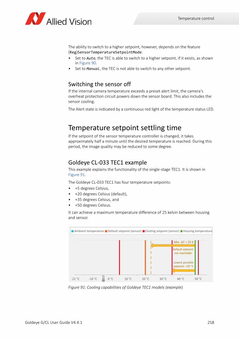
Temperature control
The ability to switch to a higher setpoint, however, depends on the feature (Reg)SensorTemperatureSetpointMode:
• Set to Auto, the TEC is able to switch to a higher setpoint, if it exists, as shown in Figure 90.
• Set to Manual, the TEC is not able to switch to any other setpoint.
Switching the sensor offIf the internal camera temperature exceeds a preset alert limit, the camera‘s overheat protection circuit powers down the sensor board. This also includes the sensor cooling.
The Alert state is indicated by a continuous red light of the temperature status LED.
Temperature setpoint settling timeIf the setpoint of the sensor temperature controller is changed, it takes approximately half a minute until the desired temperature is reached. During this period, the image quality may be reduced to some degree.
Goldeye CL-033 TEC1 exampleThis example explains the functionality of the single-stage TEC1. It is shown in Figure 91.
The Goldeye CL-033 TEC1 has four temperature setpoints:
• +5 degrees Celsius,
• +20 degrees Celsius (default),
• +35 degrees Celsius, and
• +50 degrees Celsius.
It can achieve a maximum temperature difference of 25 kelvin between housing and sensor.
Figure 91: Cooling capabilities of Goldeye TEC1 models (example)
-21 °C -10 °C 0 °C 10 °C 20 °C 30 °C 40 °C 50 °C
Ambient temperature Default setpoint (sensor) Exis ng setpoint (sensor) Housing temperature
Default setpoint not reachable
Lowest possible setpoint: +35 °C
258Goldeye G/CL User Guide V4.4.1
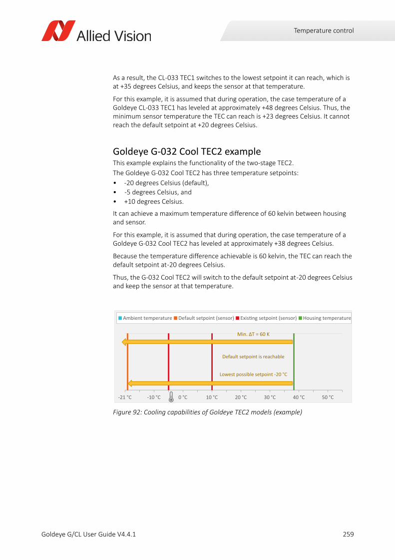
Temperature control
As a result, the CL-033 TEC1 switches to the lowest setpoint it can reach, which is at +35 degrees Celsius, and keeps the sensor at that temperature.
For this example, it is assumed that during operation, the case temperature of a Goldeye CL-033 TEC1 has leveled at approximately +48 degrees Celsius. Thus, the minimum sensor temperature the TEC can reach is +23 degrees Celsius. It cannot reach the default setpoint at +20 degrees Celsius.
Goldeye G-032 Cool TEC2 exampleThis example explains the functionality of the two-stage TEC2.
The Goldeye G-032 Cool TEC2 has three temperature setpoints:
• -20 degrees Celsius (default),
• -5 degrees Celsius, and
• +10 degrees Celsius.
It can achieve a maximum temperature difference of 60 kelvin between housing and sensor.
For this example, it is assumed that during operation, the case temperature of a Goldeye G-032 Cool TEC2 has leveled at approximately +38 degrees Celsius.
Because the temperature difference achievable is 60 kelvin, the TEC can reach the default setpoint at -20 degrees Celsius.
Thus, the G-032 Cool TEC2 will switch to the default setpoint at -20 degrees Celsius and keep the sensor at that temperature.
Figure 92: Cooling capabilities of Goldeye TEC2 models (example)
-21 °C -10 °C 0 °C 10 °C 20 °C 30 °C 40 °C 50 °C
Ambient temperature Default setpoint (sensor) Exis ng setpoint (sensor) Housing temperature
Min. T = 60 K
Default setpoint is reachable
Lowest possible setpoint -20 °C
259Goldeye G/CL User Guide V4.4.1
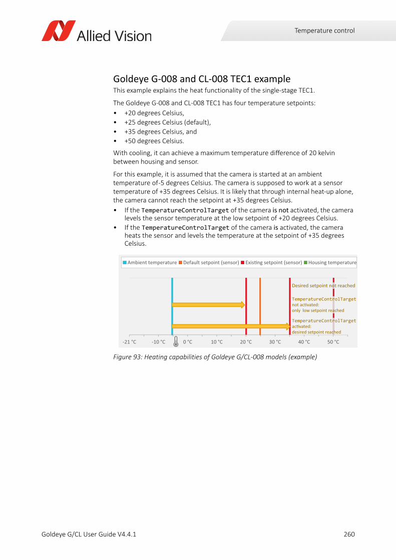
Temperature control
Goldeye G-008 and CL-008 TEC1 exampleThis example explains the heat functionality of the single-stage TEC1.
The Goldeye G-008 and CL-008 TEC1 has four temperature setpoints:
• +20 degrees Celsius,
• +25 degrees Celsius (default),
• +35 degrees Celsius, and
• +50 degrees Celsius.
With cooling, it can achieve a maximum temperature difference of 20 kelvin between housing and sensor.
For this example, it is assumed that the camera is started at an ambient temperature of -5 degrees Celsius. The camera is supposed to work at a sensor temperature of +35 degrees Celsius. It is likely that through internal heat-up alone, the camera cannot reach the setpoint at +35 degrees Celsius.
• If the TemperatureControlTarget of the camera is not activated, the camera levels the sensor temperature at the low setpoint of +20 degrees Celsius.
• If the TemperatureControlTarget of the camera is activated, the camera heats the sensor and levels the temperature at the setpoint of +35 degrees Celsius.
Figure 93: Heating capabilities of Goldeye G/CL-008 models (example)
-21 °C -10 °C 0 °C 10 °C 20 °C 30 °C 40 °C 50 °C
Ambient temperature Default setpoint (sensor) Exis ng setpoint (sensor) Housing temperature
Desired setpoint not reached
TemperatureControlTargetnot ac vated: only low setpoint reached
TemperatureControlTargetac vated: desired setpoint reached
260Goldeye G/CL User Guide V4.4.1
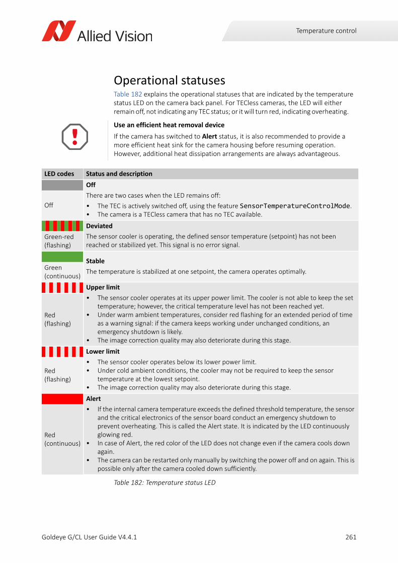
Temperature control
Operational statusesTable 182 explains the operational statuses that are indicated by the temperature status LED on the camera back panel. For TECless cameras, the LED will either remain off, not indicating any TEC status; or it will turn red, indicating overheating.
Use an efficient heat removal device
If the camera has switched to Alert status, it is also recommended to provide a more efficient heat sink for the camera housing before resuming operation.However, additional heat dissipation arrangements are always advantageous.
LED codes Status and description
Off
There are two cases when the LED remains off:
• The TEC is actively switched off, using the feature SensorTemperatureControlMode. • The camera is a TECless camera that has no TEC available.
Off
Deviated
The sensor cooler is operating, the defined sensor temperature (setpoint) has not been reached or stabilized yet. This signal is no error signal.
Green-red (flashing)
Stable
The temperature is stabilized at one setpoint, the camera operates optimally.Green (continuous)
Upper limit
• The sensor cooler operates at its upper power limit. The cooler is not able to keep the set temperature; however, the critical temperature level has not been reached yet.
• Under warm ambient temperatures, consider red flashing for an extended period of time as a warning signal: if the camera keeps working under unchanged conditions, an emergency shutdown is likely.
• The image correction quality may also deteriorate during this stage.
Red (flashing)
Lower limit
• The sensor cooler operates below its lower power limit.• Under cold ambient conditions, the cooler may not be required to keep the sensor
temperature at the lowest setpoint.• The image correction quality may also deteriorate during this stage.
Red (flashing)
Alert
• If the internal camera temperature exceeds the defined threshold temperature, the sensor and the critical electronics of the sensor board conduct an emergency shutdown to prevent overheating. This is called the Alert state. It is indicated by the LED continuously glowing red.
• In case of Alert, the red color of the LED does not change even if the camera cools down again.
• The camera can be restarted only manually by switching the power off and on again. This is possible only after the camera cooled down sufficiently.
Red (continuous)
Table 182: Temperature status LED
261Goldeye G/CL User Guide V4.4.1
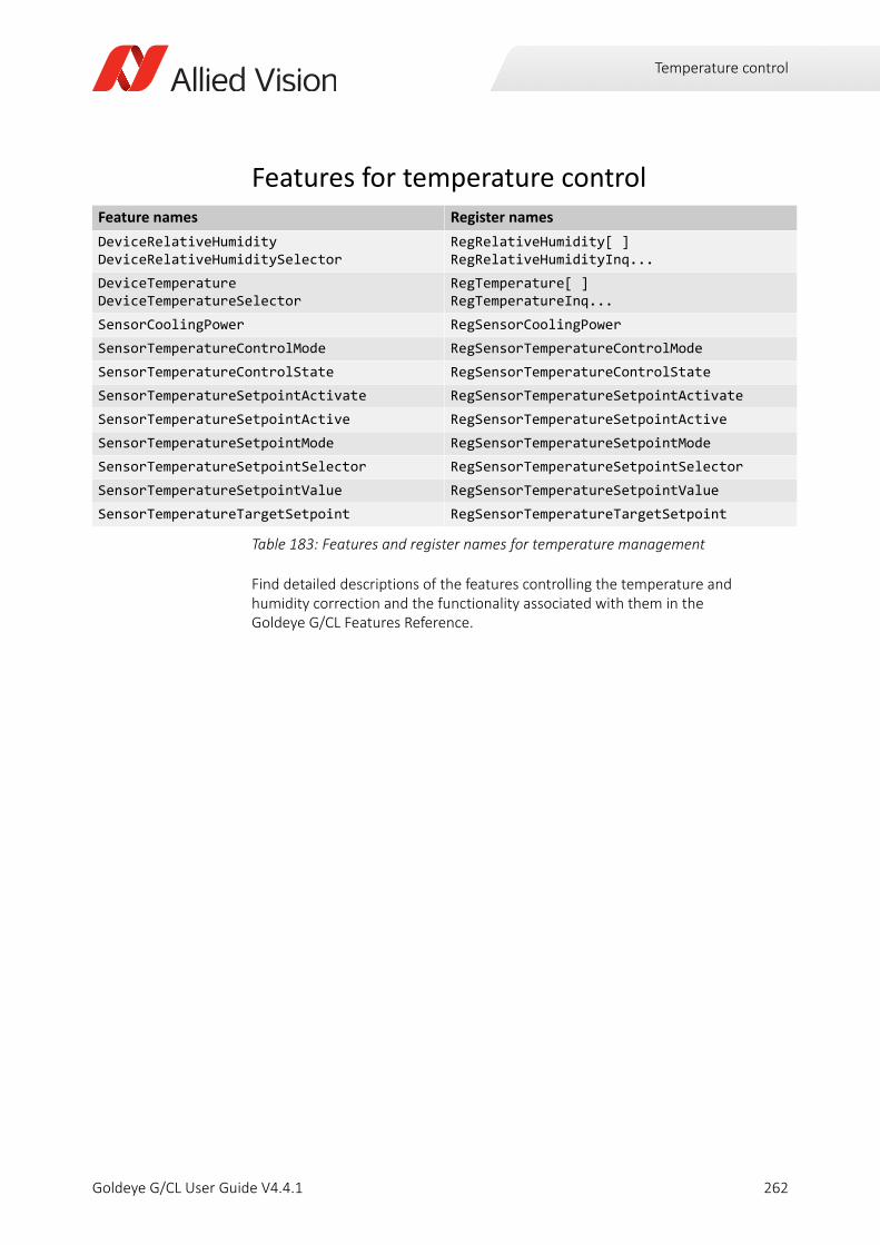
Temperature control
Features for temperature control
Find detailed descriptions of the features controlling the temperature and humidity correction and the functionality associated with them in the Goldeye G/CL Features Reference.
Feature names Register names
DeviceRelativeHumidityDeviceRelativeHumiditySelector
RegRelativeHumidity[ ]RegRelativeHumidityInq...
DeviceTemperatureDeviceTemperatureSelector
RegTemperature[ ] RegTemperatureInq...
SensorCoolingPower RegSensorCoolingPower
SensorTemperatureControlMode RegSensorTemperatureControlMode
SensorTemperatureControlState RegSensorTemperatureControlState
SensorTemperatureSetpointActivate RegSensorTemperatureSetpointActivate
SensorTemperatureSetpointActive RegSensorTemperatureSetpointActive
SensorTemperatureSetpointMode RegSensorTemperatureSetpointMode
SensorTemperatureSetpointSelector RegSensorTemperatureSetpointSelector
SensorTemperatureSetpointValue RegSensorTemperatureSetpointValue
SensorTemperatureTargetSetpoint RegSensorTemperatureTargetSetpoint
Table 183: Features and register names for temperature management
262Goldeye G/CL User Guide V4.4.1
Firmware update
Goldeye G/CL User Guide V4.4.1
This chapter explains the firmware update of Goldeye G and CL cameras.
263
Firmware update
Firmware loader applicationAllied Vision provides an application for Goldeye cameras that loads firmware to the camera, using a simple interface. New feature introductions and product improvements motivate new firmware releases. All users are encouraged to use the newest firmware available and carry out a firmware update if necessary. Updating the firmware takes a few minutes.
As long as a firmware update is in progress, the status LED indicates this with a 1 Hertz green-red flashing.
How to obtain the latest firmware versionThe firmware for Goldeye G/CL cameras is subject to export limitations. Thus, it is not available via public download.
To update the firmware of your Goldeye G/CL or Goldeye G/CL Cool camera, please visit www.alliedvision.com/en/about-us/contact-us/technical-support-repair-/-rma.
Do not power off during the firmware update
Ensure that you never power off the camera during the firmware update until the firmware update is complete, and the camera reboot has been completed.
Both firmware update and reboot are indicated by a 1 Hertz green-red flashing of the status LED.
Not complying with this requirement might damage the camera and render it unusable.
264Goldeye G/CL User Guide V4.4.1
Cleaning optical components
Goldeye G/CL User Guide V4.4.1
This chapter includes:
Avoiding the necessity of camera cleaning ........................ 266Identifying contaminations ................................................. 266Removing optical filters ...................................................... 267Cleaning instructions .......................................................... 268
265
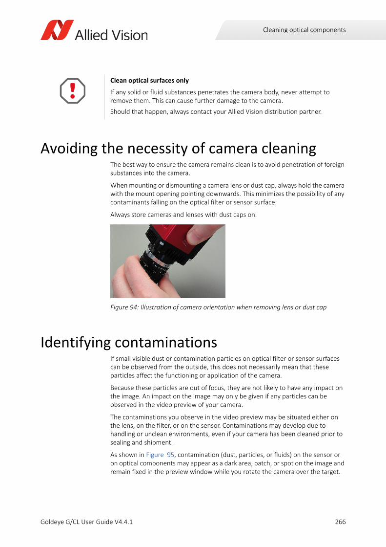
Cleaning optical components
Avoiding the necessity of camera cleaningThe best way to ensure the camera remains clean is to avoid penetration of foreign substances into the camera.
When mounting or dismounting a camera lens or dust cap, always hold the camera with the mount opening pointing downwards. This minimizes the possibility of any contaminants falling on the optical filter or sensor surface.
Always store cameras and lenses with dust caps on.
Identifying contaminationsIf small visible dust or contamination particles on optical filter or sensor surfaces can be observed from the outside, this does not necessarily mean that these particles affect the functioning or application of the camera.
Because these particles are out of focus, they are not likely to have any impact on the image. An impact on the image may only be given if any particles can be observed in the video preview of your camera.
The contaminations you observe in the video preview may be situated either on the lens, on the filter, or on the sensor. Contaminations may develop due to handling or unclean environments, even if your camera has been cleaned prior to sealing and shipment.
As shown in Figure 95, contamination (dust, particles, or fluids) on the sensor or on optical components may appear as a dark area, patch, or spot on the image and remain fixed in the preview window while you rotate the camera over the target.
Clean optical surfaces only
If any solid or fluid substances penetrates the camera body, never attempt to remove them. This can cause further damage to the camera.
Should that happen, always contact your Allied Vision distribution partner.
Figure 94: Illustration of camera orientation when removing lens or dust cap
266Goldeye G/CL User Guide V4.4.1
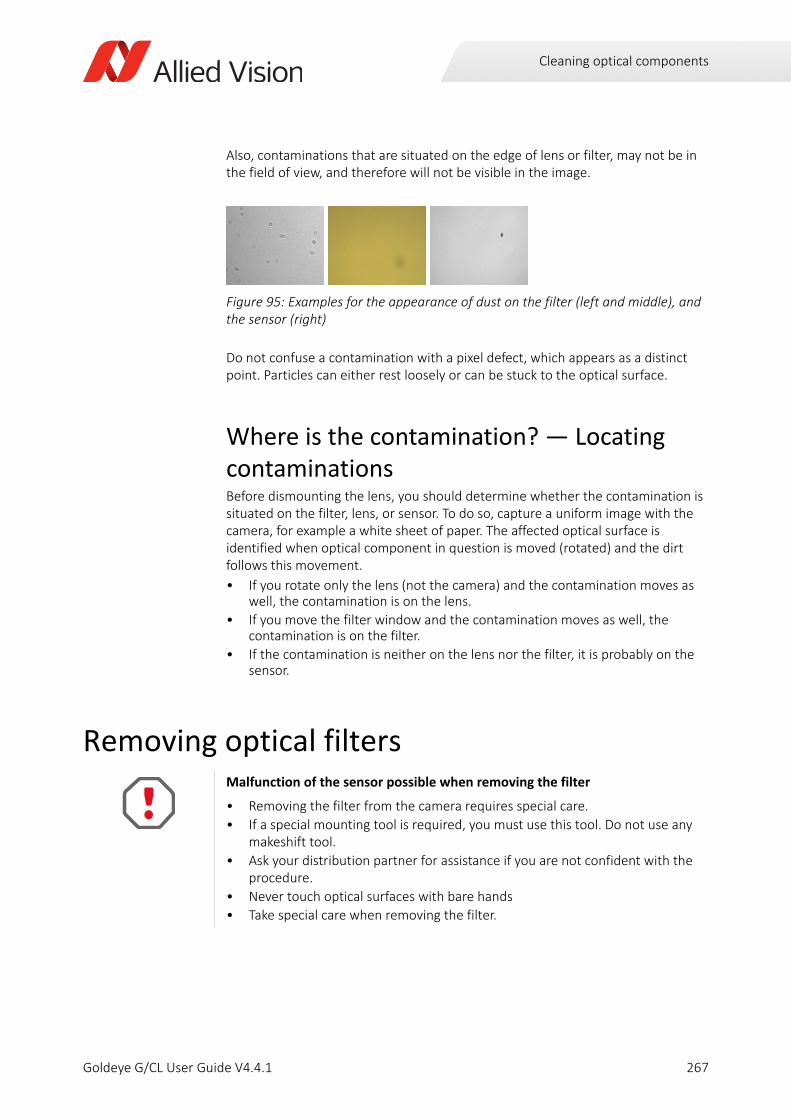
Cleaning optical components
Also, contaminations that are situated on the edge of lens or filter, may not be in the field of view, and therefore will not be visible in the image.
Do not confuse a contamination with a pixel defect, which appears as a distinct point. Particles can either rest loosely or can be stuck to the optical surface.
Where is the contamination? — Locating contaminationsBefore dismounting the lens, you should determine whether the contamination is situated on the filter, lens, or sensor. To do so, capture a uniform image with the camera, for example a white sheet of paper. The affected optical surface is identified when optical component in question is moved (rotated) and the dirt follows this movement.
• If you rotate only the lens (not the camera) and the contamination moves as well, the contamination is on the lens.
• If you move the filter window and the contamination moves as well, the contamination is on the filter.
• If the contamination is neither on the lens nor the filter, it is probably on the sensor.
Removing optical filters
Figure 95: Examples for the appearance of dust on the filter (left and middle), and the sensor (right)
Malfunction of the sensor possible when removing the filter
• Removing the filter from the camera requires special care.
• If a special mounting tool is required, you must use this tool. Do not use any makeshift tool.
• Ask your distribution partner for assistance if you are not confident with the procedure.
• Never touch optical surfaces with bare hands
• Take special care when removing the filter.
267Goldeye G/CL User Guide V4.4.1
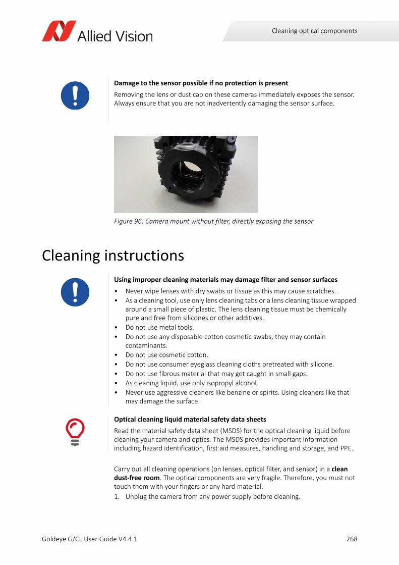
Cleaning optical components
Cleaning instructions
Carry out all cleaning operations (on lenses, optical filter, and sensor) in a clean dust-free room. The optical components are very fragile. Therefore, you must not touch them with your fingers or any hard material.
1. Unplug the camera from any power supply before cleaning.
Damage to the sensor possible if no protection is present
Removing the lens or dust cap on these cameras immediately exposes the sensor. Always ensure that you are not inadvertently damaging the sensor surface.
Figure 96: Camera mount without filter, directly exposing the sensor
Using improper cleaning materials may damage filter and sensor surfaces
• Never wipe lenses with dry swabs or tissue as this may cause scratches.
• As a cleaning tool, use only lens cleaning tabs or a lens cleaning tissue wrapped around a small piece of plastic. The lens cleaning tissue must be chemically pure and free from silicones or other additives.
• Do not use metal tools.
• Do not use any disposable cotton cosmetic swabs; they may contain contaminants.
• Do not use cosmetic cotton.
• Do not use consumer eyeglass cleaning cloths pretreated with silicone.
• Do not use fibrous material that may get caught in small gaps.
• As cleaning liquid, use only isopropyl alcohol.
• Never use aggressive cleaners like benzine or spirits. Using cleaners like that may damage the surface.
Optical cleaning liquid material safety data sheets
Read the material safety data sheet (MSDS) for the optical cleaning liquid before cleaning your camera and optics. The MSDS provides important information including hazard identification, first aid measures, handling and storage, and PPE.
268Goldeye G/CL User Guide V4.4.1
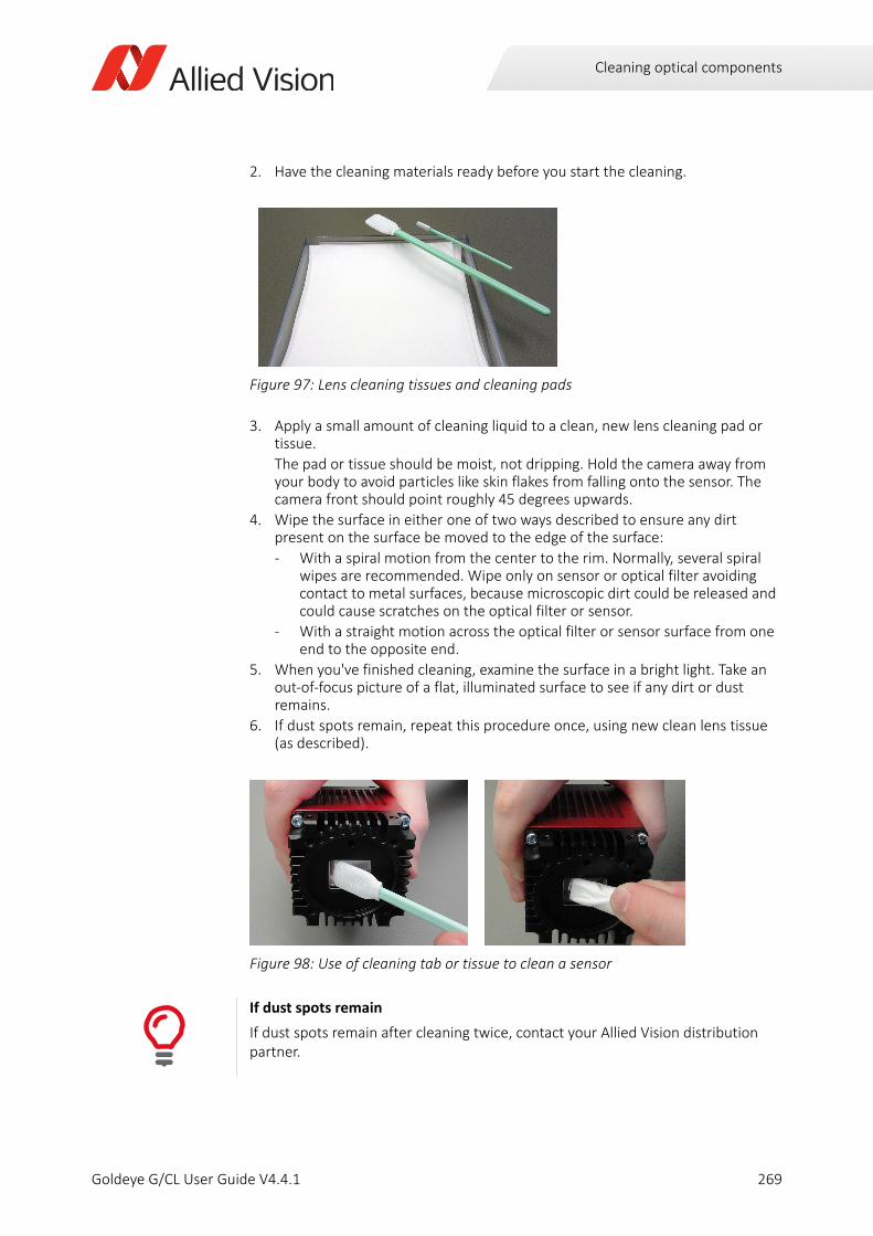
Cleaning optical components
2. Have the cleaning materials ready before you start the cleaning.
3. Apply a small amount of cleaning liquid to a clean, new lens cleaning pad or tissue.
The pad or tissue should be moist, not dripping. Hold the camera away from your body to avoid particles like skin flakes from falling onto the sensor. The camera front should point roughly 45 degrees upwards.
4. Wipe the surface in either one of two ways described to ensure any dirt present on the surface be moved to the edge of the surface:
- With a spiral motion from the center to the rim. Normally, several spiral wipes are recommended. Wipe only on sensor or optical filter avoiding contact to metal surfaces, because microscopic dirt could be released and could cause scratches on the optical filter or sensor.
- With a straight motion across the optical filter or sensor surface from one end to the opposite end.
5. When you've finished cleaning, examine the surface in a bright light. Take an out-of-focus picture of a flat, illuminated surface to see if any dirt or dust remains.
6. If dust spots remain, repeat this procedure once, using new clean lens tissue (as described).
Figure 97: Lens cleaning tissues and cleaning pads
Figure 98: Use of cleaning tab or tissue to clean a sensor
If dust spots remain
If dust spots remain after cleaning twice, contact your Allied Vision distribution partner.
269Goldeye G/CL User Guide V4.4.1
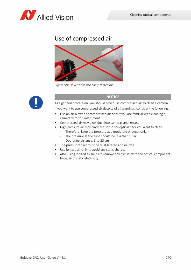
Cleaning optical components
Use of compressed air
Figure 99: How not to use compressed air
NOTICE
As a general precaution, you should never use compressed air to clean a camera.
If you want to use compressed air despite of all warnings, consider the following:
• Use an air blower or compressed air only if you are familiar with cleaning a camera with this instrument.
• Compressed air may blow dust into cameras and lenses.
• High pressure air may crack the sensor or optical filter you want to clean.
- Therefore, keep the pressure at a moderate strength only.
- The pressure at the tube should be less than 1 bar
- Operating distance: 5 to 30 cm
• The pressurized air must be dust-filtered and oil-free.
• Use ionized air only to avoid any static charge.
• Also, using ionized air helps to remove any dirt stuck to the optical component because of static electricity.
270Goldeye G/CL User Guide V4.4.1
Index
IndexAAbsolute QE
CL-008 Cool TEC1 .........................................119CL-008 TEC1 .................................................114CL-032 Cool TEC2 .........................................134CL-032 TEC1 .................................................129CL-033 TEC1 .................................................139CL-033 TECless .............................................144CL-034 TEC1 .................................................149G-008 Cool TEC1 ............................................81G-008 TEC1 ....................................................77G-032 Cool TEC2 ............................................93G-032 TEC1 ....................................................89G-033 TEC1 ....................................................97G-033 TECless ..............................................101G-034 TEC1 ..................................................105
AccessoriesBandpass filters ............................................184Camera Link cables ......................................181Ethernet adapters ........................................181Heat sink set .................................................186Hirose 12-pin connector ..............................182Hirose 4-pin connector ................................180Mount adapters ...........................................183Power adapters ............................................179
adjustmentC-Mount .......................................................197
Allied Vision contact .............................................16Applicable standards ............................................66Automatic contrast control ................................243Automatic exposure control ...............................241Automatic image control ....................................238
Accounted pixels ..........................................238Eliminating outliers ......................................238Mean value ..................................................238Outliers .........................................................238Region of interest ........................................240
AutoModeOutliers ..............................................238AutoModeRegion ...............................................240
BBackground correction .......................................235Bandpass filter ....................................................200Bandpass filters 1450 nm ...................................203
Binning ............................................................... 237Block diagram
Input signal .................................................. 221Isolated input ............................................... 217Isolated output ............................................ 219Signal output ............................................... 222
CCamera cleaning
Compressed air ............................................ 270Identifying contaminations ......................... 266Locating contaminations ............................. 267Necessity ..................................................... 266
Camera Link cables MDR to SDR ........................ 181Camera Link cables SDR to SDR ......................... 182Camera Link interface ........................................ 207Camera Link status LEDs .................................... 208Camera software
Installation ..................................................... 56Category 6 ............................................................ 45CC1 ..................................................................... 217CC2 ..................................................................... 217CC3 ..................................................................... 217CC4 ..................................................................... 217Cleaning instructions ......................................... 268C-Mount adapter
Filter change ................................................ 190Specifications ............................................... 189
ComplianceUSA ................................................................ 31
Control signals .................................................... 221Cooling
Active cooling .............................................. 250Passive cooling ............................................ 251
Copyright .............................................................. 33Correction data .................................................. 234Cut-off wavelength ............................................ 201Cut-on wavelength ............................................. 201CWL .................................................................... 201
DDecimation ......................................................... 237Defect pixel correction ....................................... 235Delay
Isolated input ............................................... 217Isolated output ............................................ 220
DimensionsGoldeye CL Cool - C-Mount ......................... 176Goldeye CL Stabilized - C-Mount ................ 170
271Goldeye G/CL User Guide V4.4.1
Index
Goldeye CL Stabilized - F-Mount .................171Goldeye CL Stabilized - M42-Mount ............172Goldeye G Cool - C-Mount ...........................165Goldeye G Cool - F-Mount ...........................166Goldeye G Cool - M42-Mount .....................167Goldeye G Stabilized - C-Mount . 158, 159, 168Goldeye G Stabilized - F-Mount ...................160Goldeye G Stabilized - M42-Mount .............161
Eelectrostatic discharge .........................................28Eliminating outliers .............................................238Environmental specifications .........................46, 58ESD ..................................................................28, 35Ethernet adapters ...............................................181Exposure .............................................................230Exposure control .................................................241External GND ......................................................215External power ...................................................215
FFilter change ...................................... 190, 193, 195F-Mount adapter
Filter change ................................................193Specifications ...............................................192
Frame grabberInstallation .....................................................56Use own transport layer ................................66
Frame grabber specific viewer .............................60Grabbing images ............................................64
Frame memory ...................................................245Frame rates and cooling .......................................74FWHM .................................................................202
GGeneral safety notes ............................................33GigE status LEDs .................................................206GPIOs
CL-008 Cool TEC1 .........................................118CL-008 TEC1 .................................................113CL-030 TEC1 .................................................123CL-032 Cool TEC2 .........................................133CL-032 TEC1 .................................................128CL-033 TEC1 .................................................138CL-033 TECless .............................................143CL-034 TEC1 .................................................148CL-130 TEC1 .................................................153G-008 Cool TEC1 ............................................80G-008 TEC1 ....................................................76
G-030 TEC1 .................................................... 84G-032 Cool TEC2 ............................................ 92G-032 TEC1 .................................................... 88G-033 TEC1 .................................................... 96G-033 TECless .............................................. 100G-034 TEC1 .................................................. 104G-130 TEC1 .................................................. 108
HHalf Power Points ............................................... 202heat dissipation .................................................... 34Hirose 12-pin connector .................................... 182
Pin assignment ............................................ 213Hirose 4-pin connector ...................................... 180
Pin assignment ............................................ 214
II/O connectors ................................................... 211Image control
Frame memory ............................................ 245Trigger-induced distortion correction ........ 245
Image correctionBackground correction ................................ 235Defect pixel correction ................................ 235Non-uniformity correction .......................... 234
Image corrections .............................................. 234Correction data ........................................... 234
Image processingBinning ......................................................... 237Decimation .................................................. 237Look-up table ............................................... 236
Imaging/Performance specificationsCL-008 Cool TEC1 ........................................ 117CL-008 TEC1 ................................................. 112CL-030 TEC1 ................................................. 122CL-032 Cool TEC2 ........................................ 132CL-032 TEC1 ................................................. 127CL-033 TEC1 ................................................. 137CL-033 TECless ............................................. 142CL-034 TEC1 ................................................. 147CL-130 TEC1 ................................................. 152G-008 Cool TEC1 ............................................ 79G-008 TEC1 .................................................... 75G-030 TEC1 .................................................... 83G-032 Cool TEC2 ............................................ 91G-032 TEC1 .................................................... 87G-033 TEC1 .................................................... 95G-033 TECless ................................................ 99G-034 TEC1 .................................................. 103
272Goldeye G/CL User Guide V4.4.1
Index
G-130 TEC1 ..................................................107In 1 - non-isolated ...............................................216In 2 - opto-isolated .............................................216Install Vimba Viewer .............................................57Interfaces
Camera Link .................................................207IP class ...................................................................71Isolated input
Delay .............................................................217Isolated Out Power .............................................216
Llenses
maximum protrusion .....................................36Look-up table ......................................................236
MM42-Mount adapter
Filter change ................................................195Specifications ...............................................195
Manual conventionsStyles ..............................................................27Symbols ..........................................................27
Mechanics specificationsCL-008 Cool TEC1 .........................................118CL-008 TEC1 .................................................113CL-030 TEC1 .................................................123CL-032 Cool TEC2 .........................................133CL-032 TEC1 .................................................128CL-033 TEC1 .................................................138CL-033 TECless .............................................143CL-034 TEC1 .................................................148CL-130 TEC1 .................................................153G-008 Cool TEC1 ............................................80G-008 TEC1 ....................................................76G-030 TEC1 ....................................................84G-032 Cool TEC2 ............................................92G-032 TEC1 ....................................................88G-033 TEC1 ....................................................96G-033 TECless ..............................................100G-034 TEC1 ..................................................104G-130 TEC1 ..................................................108
NNon-uniformity correction .................................234
OOperating conditions
CL-008 Cool TEC1 .........................................119
CL-008 TEC1 ................................................. 113CL-030 TEC1 ................................................. 124CL-032 Cool TEC2 ........................................ 134CL-032 TEC1 ................................................. 129CL-033 TEC1 ................................................. 139CL-033 TECless ............................................. 144CL-034 TEC1 ................................................. 149CL-130 TEC1 ................................................. 154G-008 Cool TEC1 ............................................ 81G-008 TEC1 .................................................... 77G-030 TEC1 .................................................... 85G-032 Cool TEC2 ............................................ 93G-032 TEC1 .................................................... 89G-033 TEC1 .................................................... 97G-033 TECless .............................................. 101G-034 TEC1 .................................................. 105G-130 TEC1 .................................................. 109
Out 1 - non-isolated ........................................... 218Out 2 - opto-isolated .......................................... 218Out 3 - opto-isolated .......................................... 218Outliers ............................................................... 238Output specifications
CL-008 Cool TEC1 ........................................ 118CL-008 TEC1 ................................................. 113CL-030 TEC1 ................................................. 123CL-032 Cool TEC2 ........................................ 133CL-032 TEC1 ................................................. 128CL-033 TEC1 ................................................. 138CL-033 TECless ............................................. 143CL-034 TEC1 ................................................. 148CL-130 TEC1 ................................................. 153G-008 Cool TEC1 ............................................ 80G-008 TEC1 .................................................... 76G-030 TEC1 .................................................... 84G-032 Cool TEC2 ............................................ 92G-032 TEC1 .................................................... 88G-033 TEC1 .................................................... 96G-033 TECless .............................................. 100G-034 TEC1 .................................................. 104G-130 TEC1 .................................................. 108
PPassband ............................................................ 201Peak Transmittance ........................................... 202Pin assignment ................................................... 211
External GND ............................................... 215External power ............................................ 215Hirose 12-pin connector ............................. 213Hirose 4-pin connector ............................... 214
273Goldeye G/CL User Guide V4.4.1
Index
In 1 - non-isolated ........................................216In 2 - opto-isolated .......................................216Isolated Out Power ......................................216Out 1 - non-isolated .....................................218Out 2 - opto-isolated ....................................218Out 3 - opto-isolated ....................................218RxD ...............................................................215TxD ...............................................................215
Pins 12-pin HirosePin 1 ..............................................................215Pin 10 ...........................................................216Pin 11 ...........................................................216Pin 12 ...........................................................218Pin 4 ..............................................................216Pin 5 ..............................................................218Pin 6 ..............................................................218Pin 8 ..............................................................215Pin 9 ..............................................................215
Pins 4-pin Hirose .................................................215Power
DC ...................................................................46Power adapters ..................................................179Power Supply ......................................................206
RRegion of interest ...............................................240Relative QE
CL-030 TEC1 .................................................124CL-130 TEC1 .................................................154G-030 TEC1 ....................................................85G-130 TEC1 ..................................................109
Resolution and ROI frame ratesCL-008 Cool TEC1 .........................................120CL-008 TEC1 .................................................115CL-030 TEC1 .................................................125CL-032 Cool TEC2 .........................................135CL-032 TEC1 .................................................130CL-033 TEC1 .................................................140CL-033 TECless .............................................145CL-034 TEC1 .................................................150CL-130 TEC1 .................................................155G-008 Cool TEC1 ............................................82G-008 TEC1 ....................................................78G-030 TEC1 ....................................................86G-032 Cool .....................................................94G-032 TEC1 ....................................................90G-033 TEC1 ....................................................98G-033 TECless ..............................................102G-034 TEC1 ..................................................106
G-130 TEC1 .................................................. 110RS232
RxD ............................................................... 215TxD ............................................................... 215
RxD ..................................................................... 215
Ssafety ......................................................2, 4, 13, 27
camera power ............................................... 35electrical connections ................................... 35heat dissipation ............................................. 34lens mounts ................................................... 34maximum protrusion ..................................... 36optical components ....................................... 36sensor ............................................................ 36
Sensorposition accuracy ......................................... 177
sensor handling .................................................... 36Single band filter ................................................ 203Specifications
C-Mount adapter ......................................... 189F-Mount adapter ......................................... 192M42-Mount adapter ................................... 195
Status LEDsCamera Link ................................................. 208GigE .............................................................. 206Temperature ............................................... 261
Stopband ............................................................ 201support ................................................................. 16
TTemperature
Control ......................................................... 250Control features .......................................... 262Emergency shutdown .................................. 261Heating of G/CL-008 .................................... 251Influence on the sensor .............................. 249Operational statuses ................................... 261stabilization ................................................. 250Status LEDs .................................................. 261Switching setpoints ..................................... 255
Tolerance (Filters) .............................................. 202Trigger
Notes ........................................................... 230Rules ............................................................ 231Timing diagram ............................................ 230
Trigger-induced distortion correction ............... 245Triggering
During the Idle state .................................... 231
274Goldeye G/CL User Guide V4.4.1
Index
During the Readout state ............................231TxD ......................................................................215
UUsing custom application .....................................66
VVimba Viewer
Adjust camera controls ..................................64Controller window .........................................64Frame grabber with own transport layer ......66Getting camera information ..........................65Information window ......................................65Installation .....................................................57Launch ............................................................62use with frame grabber specific viewer ........60
WWarm-up period .................................................250Water filter .........................................................203
275Goldeye G/CL User Guide V4.4.1