g - elastomer - yukme
TRANSCRIPT
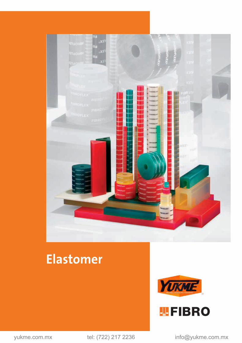
Elastomer
FIBROFLEX® Forming elastomers
The occurence of small batch lots in the press shop generally makes the more expensive dies of conventional design unadvisable – and it is in this sector in particular that FIBROFLEX® Forming elastomers can offer economical alternatives.
Over many years in the past, rubber was used for metal forming work, mostly with indifferent results because of insufficient mechanical resilience and susceptibility to damage by workshop lubricants.
FIBROFLEX®, a polyurethane elastomer of very special properties, represents a synthetic material of significant advantages over all coventional rubber substances. It provides:
• highest resistance to rupturing• outstanding elastic properties• extensive life span when used correctly• good thermal resilience• inertness to all lubricants used in metal
forming operations.
To the designer of forming- and shearing dies, FIBROFLEX® offers highly attractive solutions to many a tooling problem – as for instance the completion in one operation of intricate return flanges etc. Special mention ought to be made here of the specific suitability this elastomer exhibits in the forming of delicate surface-coated or surface-refined sheet metal.
The quite outstanding elastic properties of FIBROFLEX® have made it an almost indispensable material in toolrooms everywhere and also in many sectors of general engineering. Its numerous successful uses comprise bumper stops, strippers, ejector- and forming pads, spring elements as well as noise supression applications.
FIBROFLEX® Forming elastomers, available in three shore hardnesses to suit different conditions, are supplied in a comprehensive range of sections hollow and solid, also in sheet form of many dimensions.
Intended as suggestions for the solution of forming problems, a number of illustrated application examples are contained in this catalogue. Further detailled information on elastomer tooling can be found in our free publication “Elastomers in sheet metal forming and the toolroom”, which we shall gladly mail to interested customers.
yukme.com.mx tel: (722) 217 2236 [email protected]

Elastomer
subject to alterations
FIBROFLEX® Forming elastomers
The occurence of small batch lots in the press shop generally makes the more expensive dies of conventional design unadvisable – and it is in this sector in particular that FIBROFLEX® Forming elastomers can offer economical alternatives.
Over many years in the past, rubber was used for metal forming work, mostly with indifferent results because of insufficient mechanical resilience and susceptibility to damage by workshop lubricants.
FIBROFLEX®, a polyurethane elastomer of very special properties, represents a synthetic material of significant advantages over all coventional rubber substances. It provides:
• highest resistance to rupturing• outstanding elastic properties• extensive life span when used correctly• good thermal resilience• inertness to all lubricants used in metal
forming operations.
To the designer of forming- and shearing dies, FIBROFLEX® offers highly attractive solutions to many a tooling problem – as for instance the completion in one operation of intricate return flanges etc. Special mention ought to be made here of the specific suitability this elastomer exhibits in the forming of delicate surface-coated or surface-refined sheet metal.
The quite outstanding elastic properties of FIBROFLEX® have made it an almost indispensable material in toolrooms everywhere and also in many sectors of general engineering. Its numerous successful uses comprise bumper stops, strippers, ejector- and forming pads, spring elements as well as noise supression applications.
FIBROFLEX® Forming elastomers, available in three shore hardnesses to suit different conditions, are supplied in a comprehensive range of sections hollow and solid, also in sheet form of many dimensions.
Intended as suggestions for the solution of forming problems, a number of illustrated application examples are contained in this catalogue. Further detailled information on elastomer tooling can be found in our free publication “Elastomers in sheet metal forming and the toolroom”, which we shall gladly mail to interested customers.
G3

FIBROFLEX*accurate parts to customers specifications
*Polyurethan
G4

FIBROFLEX*accurate parts to customers specifications
*Polyurethan

Contents
subject to alterations
FIBROFLEX® - Technical data
251.FIBROFLEX®-Plate
252.FIBROFLEX®-Square rod
250.FIBROFLEX®-U-Profil rod
255.FIBROFLEX®-Hollow Square rod
253.FIBROFLEX®-Round rod
254.FIBROFLEX®-Hollow round rod
256.FIBROFLEX®-Triangular rod (60°)
257.FIBROFLEX®-Hollow triangular rod (60°)
2511.3.FIBROELAST®-Plate
2531.4.FIBROELAST®-Round rod
2541.4.FIBROELAST®-Hollow round rod
2450.Shock absorbing washer
FIBROFLEX® - Blanking, forming and embossing tools - Application examples
Blanking and forming with FIBROFLEX®-Elastomers
G6
G8-9
G10
G11
G12
G13
G14
G15
G16
G17
G18
G19
G20
G21
G23-25
G27-33

subject to alterations G7

DIN 5 6 7
Shore A 53505 80 90 95[g/cm³] 53479 1,07 1,11 1,13
[°C] -40 bis +70 -40 bis +70 -40 bis +70[%] 53512 63 45 38
[MPa] 53504 4,1 6,8 11,8[MPa] 53504 8 15,2 30
[N/mm²] 53504 36 38 49[%] 53504 450 400 360
[N/mm] 53515 21 29 50[mm³] 53516 70 50 41
[%] 53517 21 26 30
5 6 7
80 90 95
subject to alterations
Technical data on FIBROFLEX® Forming elastomer
Physical properties:FIBROFLEX®-TypeShore-A-HardnessDensity DensityWorking temperature, max. Rebound elasticity Tensile stressAt 100% elongationAt 300% elongationTensile strength Elongation at fracture Tear strengthAbrasion resistanceCompressive Set70h/24°C Resistance to Sea Water (saline) approximately 6 months
Guide lines for the machining of FIBROFLEX®:FIBROFLEX® Forming elastomers can be machined on ordinary machine tools and with conventional cutters.
A keen cutting edge is mandatory.
FIBROFLEX® TypeIdentification colour green yellow redShore-A-Hardness Sawing Circular saw, carbide-tipped, coarse toothed Rake angle 25°–30° Clearance angle 12°–15°
vc= approx. 1600 m/min.
Drilling vc= approx. 30 m/min.Turning Rake angle 25° Clearance angle 12°–15°
vc= approx. 140 m/min.
Milling Rake angle 25° Clearance angle 12°– 15°
vc= approx. 100 m/min.
vc = cutting speed
Please note that we can supply form parts, required in larger quantities, in the ready-cast condition. Enquiries are invited.
G8 subject to alterations
Technical data on FIBROFLEX® Forming elastomers
Temperature resistanceFIBROFLEX® can be used safely at temperatures up to +70°C.
FIBROFLEX® will retain most of its flexibility at temperatures as low as -40°C. A gradual increase in rigidity sets in below -18°C.
Resistance to thermal shock is excellent.
Resistance to oxygen and ozone:No traceable influences are incurred at normal atmospheric concentrations.
Resistance to aging:Aging shows no discernable effects in conditions of normal ambient tem-peratures and generally constant environmental surroundings.
Tolerance range of FIBROFLEX®- and FIBROELAST® semi-finished items:according to DIN ISO 3302-1 tolerance class M3
Water resistance:FIBROFLEX® exhibits outstanding long-term stability under exposure to water of up to +50°C. Swelling and/or destructive influences remain absent.
This typical resistance against hydrolysis is characteristic for the specific molecular structure of the elastomer. Water-Oil emulsions present no problems either.
These are clear advantages of FIBROFLEX® over other polyurethane elasto-mer structures.
Resistance to oil, chemicals, and solventsFIBROFLEX® is presenting an excellent resistance to oil and solvents and is, particularly, suiting applications in connection with lubricating oil and fuel.
Typical data of chemical resistance are shown in the following table.
Table No 1 – Resistance to some Chemicals
Diesel Fuel ○Mineral Fats, acc. to additives + to –Vegetabilic Fats +Animal Fats +Petrol (free of alcohols) ○Mineral Oils – depending on additives +Paraffin + to – Rape Seed Oil +Lubrificants on Mineral Oil Basis ○Soap Emulsions –Vaseline +Water at +95 °C –Water at +20 °C + to ○
+ resistant = can be used
○ conditionally resistant = conditional use
– not resistant = not recommended
Please note that blended oils and fats may have detrimental influence due to their various additives. In order to eliminate any risk, it is recommended ot test the elastomer under exposure to any specific oily and/or fatty sub-stance. Such tests ought to be run for several weeks.

DIN 5 6 7
Shore A 53505 80 90 95[g/cm³] 53479 1,07 1,11 1,13
[°C] -40 bis +70 -40 bis +70 -40 bis +70[%] 53512 63 45 38
[MPa] 53504 4,1 6,8 11,8[MPa] 53504 8 15,2 30
[N/mm²] 53504 36 38 49[%] 53504 450 400 360
[N/mm] 53515 21 29 50[mm³] 53516 70 50 41
[%] 53517 21 26 30
5 6 7
80 90 95
subject to alterations
Technical data on FIBROFLEX® Forming elastomer
Physical properties:FIBROFLEX®-TypeShore-A-HardnessDensity DensityWorking temperature, max. Rebound elasticity Tensile stressAt 100% elongationAt 300% elongationTensile strength Elongation at fracture Tear strengthAbrasion resistanceCompressive Set70h/24°C Resistance to Sea Water (saline) approximately 6 months
Guide lines for the machining of FIBROFLEX®:FIBROFLEX® Forming elastomers can be machined on ordinary machine tools and with conventional cutters.
A keen cutting edge is mandatory.
FIBROFLEX® TypeIdentification colour green yellow redShore-A-Hardness Sawing Circular saw, carbide-tipped, coarse toothed Rake angle 25°–30° Clearance angle 12°–15°
vc= approx. 1600 m/min.
Drilling vc= approx. 30 m/min.Turning Rake angle 25° Clearance angle 12°–15°
vc= approx. 140 m/min.
Milling Rake angle 25° Clearance angle 12°– 15°
vc= approx. 100 m/min.
vc = cutting speed
Please note that we can supply form parts, required in larger quantities, in the ready-cast condition. Enquiries are invited.
subject to alterations
Technical data on FIBROFLEX® Forming elastomers
Temperature resistanceFIBROFLEX® can be used safely at temperatures up to +70°C.
FIBROFLEX® will retain most of its flexibility at temperatures as low as -40°C. A gradual increase in rigidity sets in below -18°C.
Resistance to thermal shock is excellent.
Resistance to oxygen and ozone:No traceable influences are incurred at normal atmospheric concentrations.
Resistance to aging:Aging shows no discernable effects in conditions of normal ambient tem-peratures and generally constant environmental surroundings.
Tolerance range of FIBROFLEX®- and FIBROELAST® semi-finished items:according to DIN ISO 3302-1 tolerance class M3
Water resistance:FIBROFLEX® exhibits outstanding long-term stability under exposure to water of up to +50°C. Swelling and/or destructive influences remain absent.
This typical resistance against hydrolysis is characteristic for the specific molecular structure of the elastomer. Water-Oil emulsions present no problems either.
These are clear advantages of FIBROFLEX® over other polyurethane elasto-mer structures.
Resistance to oil, chemicals, and solventsFIBROFLEX® is presenting an excellent resistance to oil and solvents and is, particularly, suiting applications in connection with lubricating oil and fuel.
Typical data of chemical resistance are shown in the following table.
Table No 1 – Resistance to some Chemicals
Diesel Fuel ○Mineral Fats, acc. to additives + to –Vegetabilic Fats +Animal Fats +Petrol (free of alcohols) ○Mineral Oils – depending on additives +Paraffin + to – Rape Seed Oil +Lubrificants on Mineral Oil Basis ○Soap Emulsions –Vaseline +Water at +95 °C –Water at +20 °C + to ○
+ resistant = can be used
○ conditionally resistant = conditional use
– not resistant = not recommended
Please note that blended oils and fats may have detrimental influence due to their various additives. In order to eliminate any risk, it is recommended ot test the elastomer under exposure to any specific oily and/or fatty sub-stance. Such tests ought to be run for several weeks.
G9

subject to alterations
FIBROFLEX®-Plate
Execution: FIBROFLEX® is available in 3 Shore hardnesses: .5.=80 Shore A = colour: Green .6.=90 Shore A = colour: Yellow .7.=95 Shore A = colour: Red Further technical data at the beginning of Chapter G.
251.
G10
sa x b
250 x 250a x b
250 x 500a x b
500 x 500a x b
500 x 1000a x b
1000 x 10001 ● ● ● ●2 ● ● ● ●3 ● ● ● ●4 ● ● ● ●5 ● ● ● ●6 ● ● ● ●7 ● ● ● ●8 ● ● ● ● ●10 ● ● ● ● ●12 ● ● ● ● ●15 ● ● ● ● ●20 ● ● ● ● ●25 ● ● ● ● ●30 ● ● ● ● ●40 ● ● ● ● ●50 ● ● ● ● ●60 ● ● ● ●70 ● ● ● ●80 ● ● ● ●
Ordering Code (example):FIBROFLEX®-Plate =251.Spring hardness MAT 80 Shore A = 5.Thickness s 1 mm = 001.Length a 250 mm = 0250.Width b 250 mm = 0250Order No =251. 5.001. 0250. 0250
251. FIBROFLEX®-Plate

subject to alterations
FIBROFLEX®-Square rod
252.
Execution: FIBROFLEX® is available in 3 Shore hardnesses: .5.=80 Shore A = colour: Green .6.=90 Shore A = colour: Yellow .7.=95 Shore A = colour: Red Further technical data at the beginning of Chapter G.
Note: 1) Dimension b machined
G11
a b l1 250 500 1000 a b l1 250 500 10008 8 1) ● 22 22 ● ● ●8 15 1) ● 25 25 1) ●8 25 1) ● 25 40 1) ●8 50 1) ● 25 60 1) ●10 10 1) ● 25 80 1) ●10 15 1) ● 30 30 ● ● ●10 25 1) ● 40 40 1) ●10 50 1) ● 40 60 ● ● ●12 12 1) ● 45 45 ● ● ●12 20 1) ● 50 50 ● ● ●12 30 1) ● 50 180 ● ● ●12 50 1) ● 60 60 ● ● ●15 15 ● ● ● 60 80 ● ● ●15 25 1) ● 80 80 ● ● ●15 40 1) ● 80 100 ● ● ●15 50 1) ● 100 100 ● ● ●20 20 1) ● 100 125 ● ● ●20 30 1) ● 100 180 ● ● ●20 40 1) ● 125 125 ● ● ●20 50 1) ●
Ordering Code (example):FIBROFLEX®-Square rod =252.Spring hardness MAT 80 Shore A = 5.Height a 8 mm = 008.Width b 8 mm = 008.Length l1 1000 mm = 1000Order No =252.5.008. 008. 1000
252. FIBROFLEX®-Square rod

subject to alterations
FIBROFLEX®-U-Profil rod
Execution: FIBROFLEX® is available in 3 Shore hardnesses: .5.=80 Shore A = colour: Green .6.=90 Shore A = colour: Yellow .7.=95 Shore A = colour: Red Further technical data at the beginning of Chapter G.
250.
G12
a b a1 b1 l1 250 50050 50 35 20 ● ●50 75 35 30 ● ●75 100 50 40 ● ●100 200 60 120 ● ●
Ordering Code (example):FIBROFLEX®-U-Profil rod =250.Spring hardness MAT 80 Shore A = 5.Height a 50 mm = 050.Width b 50 mm = 050.Length l1 250 mm = 0250Order No =250. 5.050. 050. 0250
250. FIBROFLEX®-U-Profil rod

subject to alterations
FIBROFLEX®-Hollow Square rod
255.
Execution: FIBROFLEX® is available in 3 Shore hardnesses: .5.=80 Shore A = colour: Green .6.=90 Shore A = colour: Yellow .7.=95 Shore A = colour: Red Further technical data at the beginning of Chapter G.
G13
a b a1 b1 d1 l1 250 500 100040 60 20 35 - ● ● ●45 45 - - 20 ● ● ●50 50 - - 25 ● ● ●50 180 20 120 - ● ● ●60 60 - - 30 ● ● ●60 80 30 50 - ● ● ●80 80 - - 40 ● ● ●80 100 40 60 - ● ● ●100 100 50 50 - ● ● ●100 125 50 70 - ● ● ●100 180 50 123 - ● ● ●125 125 75 75 - ● ● ●
Ordering Code (example):FIBROFLEX®-Hollow Square rod =255.Spring hardness MAT 80 Shore A = 5.Height a 40 mm = 040.Width b 60 mm = 060.Length l1 250 mm = 0250Order No =255.5.040. 060. 0250
255. FIBROFLEX®-Hollow Square rod

subject to alterations
FIBROFLEX®-Round rod
Execution: FIBROFLEX® is available in 3 Shore hardnesses: .5.=80 Shore A = colour: Green .6.=90 Shore A = colour: Yellow .7.=95 Shore A = colour: Red Further technical data at the beginning of Chapter G.
253.
G14
d1 l1 330 500 10002 ●3 ●4 ●5 ●6 ●7 ●8 ●10 ●12 ●16 ●20 ●25 ●32 ●40 ●50 ●63 ●80 ●100 ●125 ●140 ●150 ●160 ●180 ●200 ●
Ordering Code (example):FIBROFLEX®-Round rod =253.Spring hardness MAT 80 Shore A = 5.External diameter d1 2 mm = 002Order No =253.5.002
253. FIBROFLEX®-Round rod

subject to alterations
FIBROFLEX®-Hollow round rod
254.
Execution: FIBROFLEX® is available in 3 Shore hardnesses: .5.=80 Shore A = colour: Green .6.=90 Shore A = colour: Yellow .7.=95 Shore A = colour: Red Further technical data at the beginning of Chapter G.
G15
d1 d2 l1 330 50016 6.5 ●20 8.5 ●25 10.5 ●32 13.5 ●40 13.5 ●50 17 ●63 17 ●80 21 ●100 21 ●125 27 ●140 50 ●150 50 ●160 50 ●180 50 ●200 50 ●
Ordering Code (example):FIBROFLEX®-Hollow round rod =254.Spring hardness MAT 80 Shore A = 5.External diameter d1 16 mm = 016Order No =254.5.016
254. FIBROFLEX®-Hollow round rod

subject to alterations
FIBROFLEX®-Triangular rod (60°)
Execution: FIBROFLEX® is available in 3 Shore hardnesses: .5.=80 Shore A = colour: Green .6.=90 Shore A = colour: Yellow .7.=95 Shore A = colour: Red Further technical data at the beginning of Chapter G.
256.
G16
b l1 250 50035 ● ●50 ● ●80 ● ●
Ordering Code (example):FIBROFLEX®-Triangular rod (60°) =256.Spring hardness MAT 80 Shore A = 5.Edge length b 35 mm = 035.Length l1 250 mm = 0250Order No =256. 5.035. 0250
256. FIBROFLEX®-Triangular rod (60°)

subject to alterations
FIBROFLEX®-Hollow triangular rod (60°)
257.
Execution: FIBROFLEX® is available in 3 Shore hardnesses: .5.=80 Shore A = colour: Green .6.=90 Shore A = colour: Yellow .7.=95 Shore A = colour: Red Further technical data at the beginning of Chapter G.
G17
b d1 l1 250 50035 8 ● ●50 12 ● ●80 20 ● ●
Ordering Code (example):FIBROFLEX®-Hollow triangular rod (60°) =257.Spring hardness MAT 80 Shore A = 5.Edge length b 35 mm = 035.Length l1 250 mm = 0250Order No =257.5.035. 0250
257. FIBROFLEX®-Hollow triangular rod (60°)

subject to alterations
FIBROELAST®-Plate
Material: Polyester-based polyurethane Hardness 65 Shore A
Colour: white
Note: Other plate thicknesses available upon request.
Physical properties: Shore hardness A: 65 100% modulus of elasticity: 2,4 [N/mm²] 300% modulus of elasticity: 4,6 [N/mm²] Tensile strength: 26 [N/mm²] Elongation: 550 [%] Tear resistance: 46 [kN/m]
Permanent set (70°C): 45 [%] Rebound elasticity: 58 [%] Maximum deformation: 40 [%]
2511.3.
G18
sa x b
250 x 250a x b
250 x 500a x b
500 x 500a x b
500 x 10001 ● ● ● ●2 ● ● ● ●3 ● ● ● ●4 ● ● ● ●5 ● ● ● ●6 ● ● ● ●7 ● ● ● ●8 ● ● ● ●10 ● ● ● ●12 ● ● ● ●15 ● ● ● ●
Ordering Code (example):FIBROELAST®-Plate =2511.3.Thickness s 1 mm = 001.Width a 250 mm = 0250.Length b 250 mm = 0250Order No =2511.3. 001. 0250. 0250
2511.3. FIBROELAST®-Plate

subject to alterations
FIBROELAST®-Round rod
2531.4.
Material: Polyester-based polyurethane Hardness 70 Shore A
Colour: white
Physical properties: Shore hardness A: 70 100% modulus of elasticity: 3,0 [N/mm²] 300% modulus of elasticity: 6,0 [N/mm²] Tensile strength: 28 [N/mm²] Elongation: 500 [%] Tear resistance: 58 [kN/m] Permanent set (70°C): 45 [%] Rebound elasticity: 55 [%] Maximum deformation: 40 [%]
G19
Order No d1 l12531.4.016 16 3302531.4.020 20 5002531.4.025 25 5002531.4.032 32 5002531.4.040 40 5002531.4.050 50 5002531.4.063 63 5002531.4.080 80 5002531.4.100 100 5002531.4.125 125 500
2531.4. FIBROELAST®-Round rod
subject to alterations
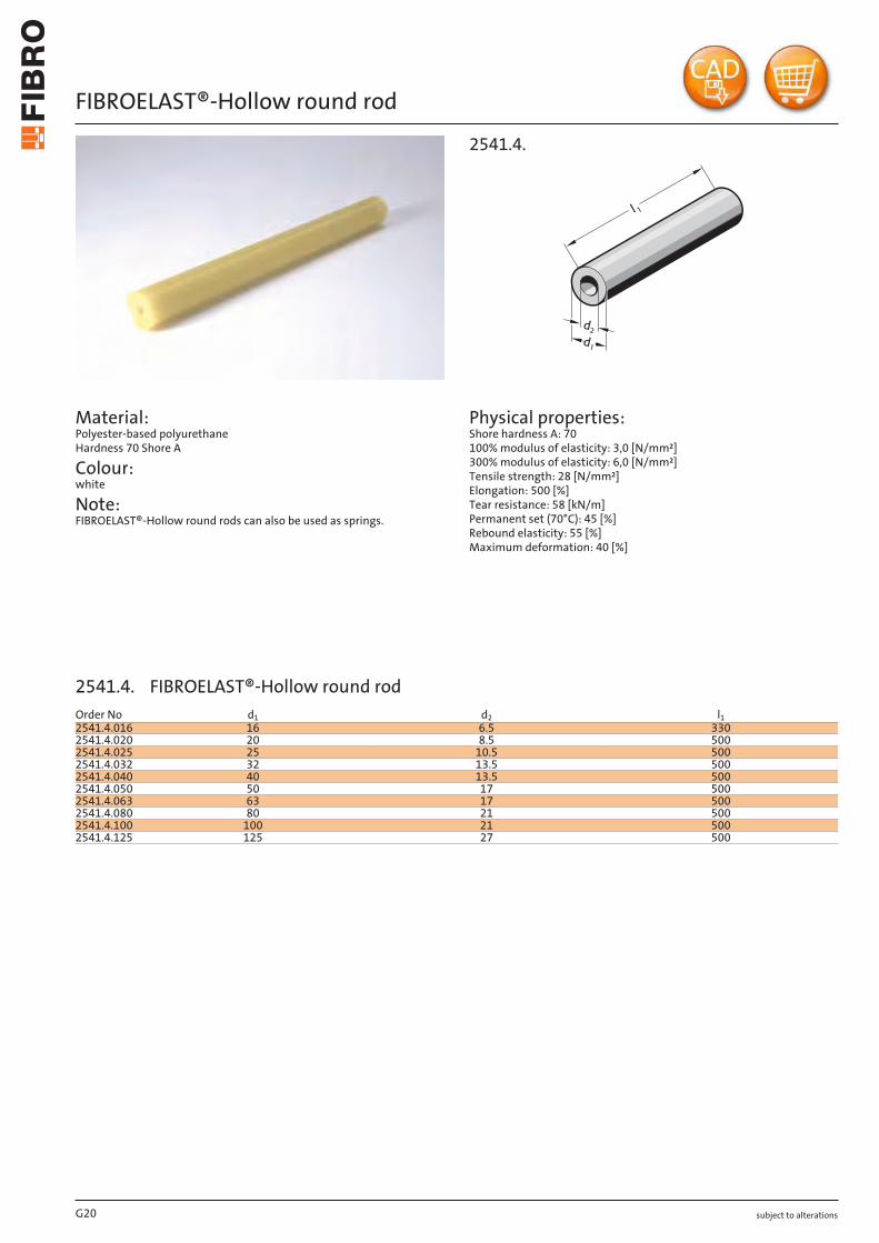
FIBROELAST®-Hollow round rod
Material: Polyester-based polyurethane Hardness 70 Shore A
Colour: white
Note: FIBROELAST®-Hollow round rods can also be used as springs.
Physical properties: Shore hardness A: 70 100% modulus of elasticity: 3,0 [N/mm²] 300% modulus of elasticity: 6,0 [N/mm²] Tensile strength: 28 [N/mm²] Elongation: 500 [%] Tear resistance: 58 [kN/m] Permanent set (70°C): 45 [%] Rebound elasticity: 55 [%] Maximum deformation: 40 [%]
2541.4.
G20
Order No d1 d2 l12541.4.016 16 6.5 3302541.4.020 20 8.5 5002541.4.025 25 10.5 5002541.4.032 32 13.5 5002541.4.040 40 13.5 5002541.4.050 50 17 5002541.4.063 63 17 5002541.4.080 80 21 5002541.4.100 100 21 5002541.4.125 125 27 500
2541.4. FIBROELAST®-Hollow round rod

subject to alterations
Shock absorbing washers
2d1d
2450.
Material: Polyurethan (FIBROFLEX®)
Execution: 2450.6. (90 Shore A) available from stock 2450.5. (80 Shore A) and 2450.7. (95 Shore A) available upon request
Mounting example
G21
d1 d2 s d1 d2 s d1 d2 s6.4 16 3 17 38 5 26 50 68.5 20 3 17 50 6 27 41 710.5 15 4 17 63 6 27 125 1010.5 25 4 18 27 4 31 42 611 17 3 18 32 7 32 40 612 24 5 21 30 5 32 49 813 19 4 21 35 7 32 60 1013 25 4 21 38 6 37 46 613.5 32 4 21 80 10 37 53 813.5 40 5 21 100 10 37 65 1014 23 4 22 28 6 42 70 1014 26 5 23.5 34 415.5 23 4 25 32 617 26 4 26 35 6
Ordering Code (example):Shock absorbing washer =2450.Shore A hardness MAT 90 Shore A = 6.Inside diameter d1 6.4 mm = 06.External diameter d2 16 mm = 016.Thickness s 3 mm = 03Order No =2450. 6. 06. 016. 03
2450. Shock absorbing washer

subject to alterationsG22

subject to alterations
Blanking, forming and embossing with FIBROFLEX® Tooling elastomer holds quite particular attraction for small to medium batches where, in comparison with conventional tooling, time and cost can be saved in the toolroom.
Conventional dies always depend on the highly accurate relationship between punch and matrix. This does not apply to elastomer dies. Only one part – punch or matrix – will be required. The “opposite member“ is provided by the elastomer cushion. This means that elastomer dies are usually made very quickly and therefore cost less. Moreover they afford great flexibility in regard of component modification at a later stage.
Whereas the foregoing considerations left the choice of an alternative solution, presswork with surface-coated or surface-refined material usually does not: with any operational blemishes firmly ruled out, more often than not the “soft touch“ of a FIBROFLEX® die is the only answer.
FIBROFLEX® Blanking dies
In the actual working cycle of en elastomer blanking die, the ram force is initially absorbed by the resistance of the deforming elastomer cushion. As the limit of deformability is reached, shearing and stock breakaway must have taken place. As a general rule it can be stated that stock of high ductility has a detrimental effect on elastomer blanking. The brittler materials on the other hand, such as spring steels, lamination quality strip and certain aluminium alloys are blanked in elastomer dies on quite a large scale. Soft materials like deep drawing steel etc. are unsuitable for the process.
Steel stock of up to 2–2,5 mm thickness can today be handled on FIBROFLEX® blanking dies, while highly accurate blanks of intricate contour can be processed from thin sheet of 0,2 to 0,01 mm thickness. It is here that the inherently uniform clamping pressure of the elastomer cushion proves its beneficial influence – as vindicated by achieveable part tolerances of ± 0,01 mm.
Metal forming with FIBROFLEX®
Projects of metal forming with FIBROFLEX® must always be based on the rule that an elastomer can be displaced but cannot be compressed. Consequently it is of para-mount importance to ensure that sufficient space is provided in an elastomer forming die for the accommodation of the displaced FIBROFLEX®
Press selection
Due to the normally somewhat greater bulk of elastomer dies, the availability of ample die space in the press has to be assured.
Hydraulic presses with their characteristic slow pressure rise are eminently suitable for elastomer tooling because this feature matches the somewhat delayed deformation behaviour of FIBROFLEX®. For the same reason, mechanical presses may give a certain amount of trouble because of overloading.
Since no demands need be made on press accuracy, older machines can often be put to good use again with FIBROFLEX® tooling.
Provided applications follow these general guide lines, FIBROFLEX® Tooling elastomer will prove its enormous resilience time and again – giving shape to workpieces without losing its own.
Recommendations for blanking, forming and embossing operations with FIBROFLEX® Elastomer
G23

subject to alterations
Application examples of forming operations with FIBROFLEX® Elastomers
Vee-BendingOne of the easiest elastomer-forming operations is that of Vee-bending off a solid punch and into a die cushion of stacked FIBROFLEX® pads.
The necessary penetration of the punch and the amount of over-bending depend on the thickness, hardness and type of the material – and further-more on the bending radius, the length of the free legs on the piece part, and lastly on the Shore hardness of the cushion.
Applicable to all kinds of bending operations is the general rule: the smaller the bending radius, the less will be the spring-back of the bend and the shallower is the required penetration of the punch.
Especially with larger batch quantities it is advisable to ensure all-round retention of the stacked elastomer cushion; it also pays to make punch and cushion identical in length.
Bending of Vee- and U-ShapesBending of Vee- and U-shapes can be achieved either with stacked FIBROFLEX® pads of different hardness (Fig. 5), or with the aid of solid and hollow FIBROFLEX® Sections. These may consist of squares, channels or triangular sections.
Where solid sections or sheet is used as a cushion, wear of the elastomer material can be reduced through creation of an additional displacement space at the bottom of the cushion retainer box, similar to Fig. 11, where gib inserts are placed along the corners.
Hollow cushions, as well as those of a channel configuration, exhibit grea-ter die life and are therefore the preferred choice for bending operations.
In the case of a U-shaped bend with straight bottom it may be advisable to insert a packing of 3–5 mm thickness, and of the same width as the flat bottom of the bend, underneath the cushion. This measure increases the forming pressure and helps to achieve a flat bottom on the workpiece.
The punch should be relieved on both sides in order to avail compensation possibilities for springback.
U-Bends with large radiusU-bends with a large bottom radius are difficult to accomplish. Punch penetration must of need be large; springback can be quite considerable.
In order to achieve good results, the use of hollow FIBROFLEX® sections or of channels becomes almost mandatory. This is illustrated in Figs. 7 and 12. Another alternative consists of machined form cushions in accordance with Fig. 13.
The hollow space of the channel-shaped cushion has the effect of increa-sing the horizontal pressure component in the die; this also holds true for hollow die cushions.
In all cases is it necessary to ensure that the cushion retainer box is suffi-ciently rigid.
Displacement possible:
a1 = 30-40% of a b1 = 30-40% of b
Fig. 5
Displacement possible:
a1 = 40-50% of a b1 = 50-60% of b
Fig. 6
Displacement possible:
a1 = 50-60% of a b1 = 50-60% of b
Fig. 7
G24

subject to alterations
FIBROFLEX® Triangular sections are shaped to fit into the existing forming grooves of bending brake dies, thus eliminating die changes and/or the provision of a die cushion retainer box as required with square cushion configurations.
Fig. 8
Fig. 10
Displacement possible:
a1 = 50 - 60% of a b1 = 50 - 60% of b
Fig. 11
Displacement possible:
a1 = 40 - 50% of a b1 = 50 - 60% of b
Fig. 12
Displacement possible:
a1 = 50 - 60% of a b1 = 60 - 70% of b
Fig. 13
Displacement possible:
b1 = 60 - 70% of b
Depending on stock specifications the bending of a channel section may either be done off a Vee-shaped punch as a voluntary choice – or it may become an absolute necessity.
Two operational sequences are required, and a goose-necked punch confi-guration is essential.
Fig. 9
Application examples of forming operations with FIBROFLEX® Elastomers
G25

Blanking and forming with FIBROFLEX®- Elastomers

Blanking and forming with FIBROFLEX®- Elastomers
G27
subject to alterations
Blanking and forming with FIBROFLEX®-Elastomers
DescriptionFIBROFLEX® forming materials for blanking, embossing and forming are eminently suitable for use in small and medium series production. The main advantage is the reduction in tooling costs compared with traditional productions methods.
This means that, even with considerable work-piece changes or with prototypes, you can res-pond quickly to changing market requirements and delivery times.
You can avoid scratching or damaging the icrea-singly common coated an highly polished sheet metals by using the gentle touch of elastome-ters for the forming process.
Forming with FIBROFLEX®When forming using elastometers, always remenber the golden rule: whatever the extent of the deformation, the elastic FIBROFLEX® forming material remains constant, i.e. it can be displaced, but not compressed. The design must allow the elastomer to “flow” into a relief gap – that is the secret of success.
Choice of machineWhen FIBROFLEX® matrices are used for blanking, embossing and forming the ma-chine must be able to accommodate the displacement.
Hydraulic presses are preferable to mechani-cal presses because of their gradual pressure build-up which suits the characteristics of the FIBROFLEX® forming material as it changes shape.
If a mechanical press is overloaded as it appro-aches bottom dead centre (which is also the cutting point), there is an risk of the press being damaged.
With FIBROFLEX® the machine is not subjected to any stresses, so even old machines can be used.
G28 subject to alterations
FIBROFLEX® Forming tool blanking – drawing – embossing
Combined blanking – embossing – punchingThe workpiece is completed at one pass. The shape is determined by the combined blanking, hole cutting and embossing matrix blank holder punch, without a reverse shape mould on the cushion side.
The thrust plate in the carrier produces a concentration of pressure which produces a better result in the active tool range. The thrust plate also provi-des the necessary compensation for constant volume.
When producing workpieces of a different shape, only the tool elements in the lower section which produce the shape have to be exchanged.

subject to alterations
Blanking and forming with FIBROFLEX®-Elastomers
DescriptionFIBROFLEX® forming materials for blanking, embossing and forming are eminently suitable for use in small and medium series production. The main advantage is the reduction in tooling costs compared with traditional productions methods.
This means that, even with considerable work-piece changes or with prototypes, you can res-pond quickly to changing market requirements and delivery times.
You can avoid scratching or damaging the icrea-singly common coated an highly polished sheet metals by using the gentle touch of elastome-ters for the forming process.
Forming with FIBROFLEX®When forming using elastometers, always remenber the golden rule: whatever the extent of the deformation, the elastic FIBROFLEX® forming material remains constant, i.e. it can be displaced, but not compressed. The design must allow the elastomer to “flow” into a relief gap – that is the secret of success.
Choice of machineWhen FIBROFLEX® matrices are used for blanking, embossing and forming the ma-chine must be able to accommodate the displacement.
Hydraulic presses are preferable to mechani-cal presses because of their gradual pressure build-up which suits the characteristics of the FIBROFLEX® forming material as it changes shape.
If a mechanical press is overloaded as it appro-aches bottom dead centre (which is also the cutting point), there is an risk of the press being damaged.
With FIBROFLEX® the machine is not subjected to any stresses, so even old machines can be used.
subject to alterations
FIBROFLEX® Forming tool blanking – drawing – embossing
Combined blanking – embossing – punchingThe workpiece is completed at one pass. The shape is determined by the combined blanking, hole cutting and embossing matrix blank holder punch, without a reverse shape mould on the cushion side.
The thrust plate in the carrier produces a concentration of pressure which produces a better result in the active tool range. The thrust plate also provi-des the necessary compensation for constant volume.
When producing workpieces of a different shape, only the tool elements in the lower section which produce the shape have to be exchanged.
G29
subject to alterations
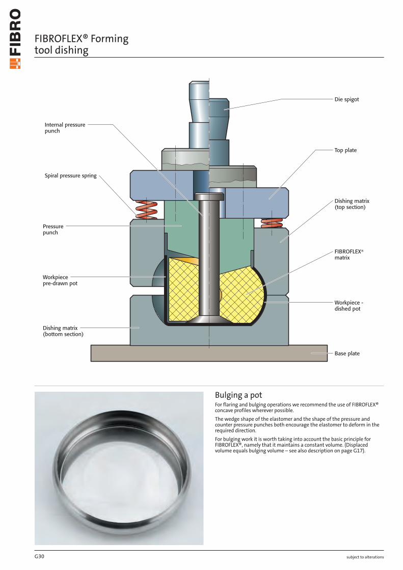
FIBROFLEX® Forming tool dishing
Bulging a potFor flaring and bulging operations we recommend the use of FIBROFLEX® concave profiles wherever possible.
The wedge shape of the elastomer and the shape of the pressure and counter pressure punches both encourage the elastomer to deform in the required direction.
For bulging work it is worth taking into account the basic principle for FIBROFLEX®, namely that it maintains a constant volume. (Displaced volume equals bulging volume – see also description on page G17).
G30 subject to alterations
FIBROFLEX® Universal blanking and forming carrier
FIBROFLEX® blanking matricesWhen blanking with elastomers, the workpiece materials, in contrast to the traditional blanking of workpiece materials, are subjected to their elastic limits, beyond which the material breaks.
The thickness of sheet steel which can be cut usting FIBROFLEX® is current-ly up to 2.5 mm.
The even clamping pressure which is excellent for pressing also means that parts with intricate contours can be manufactured.
It is possible to achieve workpiece accuracy of ± 0,01 mm.
During the blanking process the press pressure first deforms the elasto-mer. As soon as the elastomer reaches the limits of its deformation the workpiece is cut.
The less the stretch of the sheet metal, the easier it can be cut using the elastomer blanking process. Spring band steels, electric sheets and sheet aluminium all cut well using this process. Deep-drawing sheet steel is unsuitable for the elastomer blanking process.

subject to alterations
FIBROFLEX® Forming tool dishing
Bulging a potFor flaring and bulging operations we recommend the use of FIBROFLEX® concave profiles wherever possible.
The wedge shape of the elastomer and the shape of the pressure and counter pressure punches both encourage the elastomer to deform in the required direction.
For bulging work it is worth taking into account the basic principle for FIBROFLEX®, namely that it maintains a constant volume. (Displaced volume equals bulging volume – see also description on page G17).
subject to alterations
FIBROFLEX® Universal blanking and forming carrier
FIBROFLEX® blanking matricesWhen blanking with elastomers, the workpiece materials, in contrast to the traditional blanking of workpiece materials, are subjected to their elastic limits, beyond which the material breaks.
The thickness of sheet steel which can be cut usting FIBROFLEX® is current-ly up to 2.5 mm.
The even clamping pressure which is excellent for pressing also means that parts with intricate contours can be manufactured.
It is possible to achieve workpiece accuracy of ± 0,01 mm.
During the blanking process the press pressure first deforms the elasto-mer. As soon as the elastomer reaches the limits of its deformation the workpiece is cut.
The less the stretch of the sheet metal, the easier it can be cut using the elastomer blanking process. Spring band steels, electric sheets and sheet aluminium all cut well using this process. Deep-drawing sheet steel is unsuitable for the elastomer blanking process.
G31

subject to alterations
FIBROFLEX® Forming tool drawing – embossing
Drawing and embossingThe limits for flaring and bulging depend on the workpiece material, its thickness and hardness and also the height of the FIBRO FLEX® cushion.
Maximum permissible deformation of the FIBROFLEX® cushion:
80 Shore A – 35% 90 Shore A – 30% 95 Shore A – 25%
G32 subject to alterations
FIBROFLEX® Forming tool for flaring pipes
Flaring pipesWhen flaring using FIBROFLEX®, split cheeks with a conical external sur-round are required to allow the workpiece to be released.
Depending on wall thickness, flaring ratios of 1.2 can be achieved. Above a workpiece diameter-to-length ratio of 2 : 1 it is advisable to use concave cushions with bolt guides.

subject to alterations
FIBROFLEX® Forming tool drawing – embossing
Drawing and embossingThe limits for flaring and bulging depend on the workpiece material, its thickness and hardness and also the height of the FIBRO FLEX® cushion.
Maximum permissible deformation of the FIBROFLEX® cushion:
80 Shore A – 35% 90 Shore A – 30% 95 Shore A – 25%
subject to alterations
FIBROFLEX® Forming tool for flaring pipes
Flaring pipesWhen flaring using FIBROFLEX®, split cheeks with a conical external sur-round are required to allow the workpiece to be released.
Depending on wall thickness, flaring ratios of 1.2 can be achieved. Above a workpiece diameter-to-length ratio of 2 : 1 it is advisable to use concave cushions with bolt guides.
G33

Calle Ignacio Zaragoza #7Colonia Sta Ana Tlapaltitilán C.P. 50160Toluca de Lerdo, Estado de México
YUKME
Representante para México
[email protected] · www.yukme.com.mx