g-403 user manual-v2 - vnstw. · pdf fileg-403 user manual document: g-40302 ----- 1 g-403...
TRANSCRIPT

G-403 User Manual Document: G-40302
------------------------------------------------------------------------------------------------------------------------------------------------
1
G-403 Quick User Guide
For Preset display mode user
1. Check User Manual (UM) to select the display mode # as you need. Please also pay attention to the Bezel
Correction setting.
2. Set Display Mode dip SW based on the modes #. If the No. is 125, it means the dip SW pin 1, 2 & 5 should be
set at ON (up) position. All the rest is still at OFF (down) position.
3. Install the LCD display as showed in UM with correct position, angle and direction.
4. Disable ‘OVERSCAN” function if you use conventional TV. Otherwise the image location may be shifted.
5. Disable ‘Matrix” control function in the LCD. Otherwise, the image location will be shifted.
6. Select input port and set EDID in G-403 ([Options]�[Setting]�[EDID])..
7. Power on signal source, G-403 and LCD, then you will see the result.
8. User can set the time for automatically turn off output signals if no input signal is detected.
9. If there is image shift, please check if you select the right mode for bezel compensation.
10. If you want to add PIP or display two contents on the video wall, please enable PIP/POP mode.
11. If any change is required in Dip SW, please turn system OFF & ON again to get new setting.
12. Please check output LED indicators and make sure all output LED is ON. It means GeoBox had handshake
with display devices already.
13. You can connect a monitor via loop out port to see original signal for easy system operation.
14. Please note that poor cable or long distance connection may cause dot noise or unstable signal.
G-403 Advanced applications through remote controller and OSD
1. User can use more advanced functions by OSD menu through remote controller.
2. If GeoBox is installed at a location that can’t be directly accessed by remote controller, please connect IR
Extender to IR Ext connector on the back panel and set IR receiver at a position that can be accessed.
3. Turn all Dip SW pins in [Main Input] to OFF position to switch the authority of the system control to OSD
setting. If any [Main Input] Dip SW is turned to ON position, Dip SW setting command will be the 1st priority to
execute if OSD setting is conflicted with Dip SW setting.
4. Apply input signal and select input port by OSD and remote controller.
5. User can set the time for automatically turn off output signals if no input signal is detected. Once the input
signal appears again, the system will power on automatically. It is convenient for system power management.
6. User can open OSD and access to [Video Wall]�[Output Mode] menu to select Preset display mode. The
result is the same as manual DIP SW selection. User can’t fine-tune image position.
7. More flexible PIP/POP settings can be implemented from OSD menu.
8. User can create his own display mode with LCD at any angle and position by OSD [Manual Mode] or GAlign
PC Tool. User can fine-tune image position in Manual mode settings.
9. If necessary, user can connect a monitor via loop out port to see original signal for easy system operation.
10. New RC-700 remote controller allows user to access all [Manual Mode] operation without seeing OSD menu.
User can select [Index]� [TV#]� [Top Left] or [Top Right] corner to input coordinate directly and set image

G-403 User Manual Document: G-40302
------------------------------------------------------------------------------------------------------------------------------------------------
2
position. A new menu [Position] next to [Top Right] menu allows user to shift each LCD image position
without affection image rotation angle and size. It is more convenient for image position fine-tune.
11. After finishing OSD operation, please save the result in [Profile] menu.
12. For cascade and more advanced operations, please see more details in User Manual.
13. When you operate [Video Wall] setting, it may have frame tear in the display. It will disappear when you
power OFF/On the system.
How to create custom display mode by user
1. User can create all kinds of playback modes for regular, portrait and irregular video wall with different size,
resolution and bezel LCDs at any angle and position through input the coordinates of two corners in each
LCD--Top left and Top Right.
2. 4 LCD as one display units and can be cascaded without number limitation. The display panel shall be at
16:9 aspect ratio. Different aspect ratio LCD requires customized settings in factory.
3. User can convert physical design drawings into 1920x1080 coordinates and pick up the coordinates at Top
Left and Top Right corners in each LCD active display region, then input to G-403 through OSD or PC tool to
get the result. The original point for the coordinate system is set at Top Left corner as (0, 0).
4. Please note that the coordinate system (16:9) in H&V directions should have the same scaling ratio. In below
example, user can only take horizontal direction to full scale but the vertical direction remains same blanking
borders. Please design “Video Wall” at the center position to get more flexibility. After the video wall is
created, user can use [Ratio] and [Position] function to adjust aspect ratio and final image position freely.
5. In above drawing, the coordinates for TV1 and TV2 are as follows:
TV1 coordinate for Top Left corner=(0, 586),Top Right corner=(366, 216)
TV1 TV2

G-403 User Manual Document: G-40302
------------------------------------------------------------------------------------------------------------------------------------------------
3
TV2 coordinate for Top Left corner=(815, 635),Top Right corner=(447, 286)
6. Please pay attention to the display direction of the TV
7. Procedures to key-in coordinates into G-403 via OSD menu:
[Video wall]� [Manual Mode]� [Index 1~Index5] (select location to save settings)� select LCD [TV 1~4]�
select [Top Left/Top Right]� Slide bar to input Coordinates� Done
User can user RC-700 remote controller to key-in the coordinates of the image for each LCD:
Select [Index]� [TV#]� [Top left] or [Top Right] corner� [Direction key] to input coordinate.
8. GAlign PC tool is available to key-in the coordinates into G-403 through RS232 connection and click [Write]
to download GAlign setting into G-403. It also can do H&V aspect ratio and image position shift. [Read] back
function can catch existing setting values and modify through PC tool. It is important for the application that
OSD menu can’t be seen on the screen in large video wall.
9. User can also take picture of the LCD array and put this photo into a 1920x1080 coordinates system and
collect 8 points of the coordinates for 4x LCD, then input these numbers into G-403. Below are the process:
a、 Use Microsoft Picture Manager to trim the edge and only keep LCD active display region.
b、 The photo shall be corrected without distortion. If necessary, user can use [RealWorld Paint] freeware
to correct it: [Open file]� [Edit]� [Select All]� [Transformation]� [Perspective/Bezier Transformation]
c、 To view this photo file in Microsoft “Paint” � [Resize] the photo into 1920x1080 resolution.
d、 Use Mouse to click Top Left and Top Right corners in each LCD active display area to capture the
coordinates for the display. To input the coordinates into G-403 through OSD GAlign PC tool.
e、 Other software like Adobe Photo Shop can also be used to correction the distortion and catch
coordinates for the photo.
f、 Please see more details in User Manual.
10. Video wall more than 4LCD and multiple G-403 cascade
a、 If the video wall is designed with more than 4x LCD, user needs to user multiple units of G-403 and can
have two choices:
i. To consider the whole video wall as one full HD video. Assign each LCD to any G-403 output, and
catch the image coordinate for each LCD and input to G-403, then user will get the image he needs.
ii. If user wants to have higher resolution in the video wall, then user needs to split the image into
several full HD sections and assign each section to different G-403 (up to 4x LCD). User can apply
the same procedures as mentioned in previous section to assign the image to each LCD.
b、 G-403 has one [Video wall] function to allow user to split the image using [ZOOM] menu and assign the
image to each G-403 using [PAN] menu. If the cutting image has some overlap region or position shift
among G-403, user can use [Overlap] menu to align the position among different G-403.
c、 Usually, one full HD video can be applied to a video wall up to 6mx3.5m if the watching distance is more
than 3 meters (3mm pixel pitch). If the watching distance is 2 meters, the suitable video wall size is
about 4mx2.3m (about 2mm pixel pitch).
11. Portrait display mode:
If the display is at portrait position, user can apply the same procedures as above to build the video wall. User
can also rotate the video wall at 90/270 degrees and collect the coordinates to build the system to get higher
input resolution and better video quality. After installation, user needs to apply 90/270 degrees rotated
content to get correct display angle.

G-403 User Manual Document: G-40302
------------------------------------------------------------------------------------------------------------------------------------------------
4
12. Fine–tune image position
a、 Please apply video wall test pattern and check if further position adjustment is required or not. Please
download from website.
b、 For simple video wall array, user can use OSD to change [Top Left] and [Top Right] coordinates to do
fine tune. [Position] menu next to [Top right] menu can do image position shift for each LCD in H&V
directions without change the image rotation angle and size. It is convenient for position fine-tune.
c、 For large video wall or irregular array, user may not see the OSD. It will be more convenient and easier
to use GAlign PC tool for image position fine-tune. Please apply [Real Time] mode in GAlign tool so that
user can see the real time position change for easy alignment.
d、 Please figure out the relation among 4 corners in a screen with 16:9 aspect ratio. If one corner is fixed,
and change the position in the second corner, the image position and size will be also changed to show
a new image in 16:9 aspect ratio.
e、 OSD [Position] next to [Top Right] coordinate input menu can adjust the image position for each LCD at
H&V direction without change the rotation angle and size of the image. It is convenient for position
fine-tune adjustment.
f、 User needs to save the settings into [Option]� [Settings]� [Profile]� [Save]� [Index].
13. Signal source operation issue
a、 In some case, user may be difficult to see the operation menu of signal source.
b、 The best way is to set video player with “Auto-Run” so that end user can power on the signal source
and automatically playback. G-403 can auto power on/off according to the input signal detecting.
c、 If no auto-run function in video player, user can connect one monitor to the last G-403 loop out port as
monitoring devices for easy video source playback operation.
d、 If user can see OSD menu, user can select different [Index] or to select different display mode under
[Video Wall] � [Output Mode] menu to display full screen content in each LCD. After set video source,
then turn back to required Index.
e、 User can also set input dip SW manually and turn off/on the system again to get four independent full
screen displays for user to do further signal source operation.
f、 After signal source can normally playback, user can recall Profile Index by [OTH] key in remote
controller to get final result.
Image looping playback and automatic image position shift for LCD protection
1. User can create up to five playback modes and execute looping playback with selectable time interval and
playback modes.
2. Different playback mode shall come from the same input port. One of the application is that user can display
a product at different rotation angle or zoom in/out the product to see different feelings. User can also display
a series of products on the screen and pop up each product at different time interval.
3. By the same concept, user can slightly shift the image at some interval to prevent burn-in mark in LCD to
extend the life time of the LCD panel. This is important for a still image display on the LCD.
4. When user can’t see full screen operation menu in signal source due to irregular display, user can change
the display ratio or shift image position to see operation menu.

G-403 User Manual Document: G-40302
------------------------------------------------------------------------------------------------------------------------------------------------
5
Dynamic aspect ratio change and position shift across entire video wall
1. User can change entire video wall image (4 LCD) aspect ratio from 50% to 200% at both horizontal and
vertical direction through OSD and save into [Manual Mode]� [Index].
2. This function allows users to select different [Index] to display contents on the screen from different signal
sources but still maintain required aspect ratio without distortion.
3. Entire video wall image position can be shifted at H/V direction. It is helpful to crop image and highlight on the
screen and convenient for image alignment in multiple units cascade application.
4. The above aspect ratio and image shift functions can be save into [Manual Mode]� [Index] for looping
playback so that viewer will see dynamic switching images on the screen to get more impressive feeling.
Other notice
1. GAlign PC tool is convenient for irregular video wall setup. Please download from website.
2. GPM (GeoBox Parameter Manager) provides a function for user to backup or duplicate the settings from one
G-403 to another unit. Please also download from website.

G-403 User Manual Document: G-40302
------------------------------------------------------------------------------------------------------------------------------------------------
6
G-403 User Manual
Sales & Technical support:
E-mail: [email protected]
Tel: +886-2-2792-2819, Mobile: +886-935-678-033
Website: www.vnstw.com, Skype: vns-inc
Version: 2.05

G-403 User Manual Document: G-40302
------------------------------------------------------------------------------------------------------------------------------------------------
7
Table of Contents
1 Introduction……………………………………………………………..……………….… 10
2 Specifications…………………………………………………………..………….……… 11
3 Helpful tips for installation and operation…………………………………….……... 13
4 Outlook and key functions………………………………………..………………….…. 14
5 Preset display modes……………………………………………..…………….……….. 14
5.1 LCD (TV) selection.…………………….……………………..……………..……… 14
5.2 Bezel compensation………………….……………………..……….…………….. 14
5.3 Remote controller operation for manual mode settings............................... 14
5.4 PIP/POP settings…………………………………………….………….………….. 15
5.5 Preset display mode list…………………………………….……….……………. 17
5.6 How to set DIP SW…………………………………………………….……….…… 23
5.7 Signal source output resolution selection……………………………………… 24
6 G-403 Application case study…………………………………………….…….………. 25
6.1 Preset mode: Mode 145……………………..…………………….….………….... 25
6.2 Preset mode: Mode 00……………………………………………………..………. 25
6.3 Preset mode: Mode 01……………………………………………………..………. 26
6.4 Preset mode: Mode 03……………………………………………………..………. 26
7 Multiple G-403 cascade……………………...…………………………….….………….. 27
7.1 Setup procedures….………………………………………………………..………. 27
7.2 Signal source resolution selection…..……………………………………..……. 27
7.3 Case study a: 4k/2k 4x4 video wall………………………………………….…… 27
7.4 Case study B: 4k/2k 3x3 video wall……………………………………….……… 28
7.5 Case study C: 4k/2k 8x TV irregular video wall…………………………….….. 28
8 Multiple contents in cascaded display………………………………………………… 29
9 Examples for cascaded display…………………………………………………………. 30
10 OSD menu and functions…………………………………………………………………. 34
10.1 [Picture] color adjustment………………………………………………………… 35
10.2 [Image Setup] for PC graphics VGA input………………………………………. 35
10.3 [Image Properties]…………………………………………………………………… 35
10.3.1 Color.………………………………………………………………………… 36
10.3.2 Scaling………………………………………………………………………… 36
10.3.3 PIP/POP settings……………………………………………………………. 36
10.3.4 Image Orientation…………………………………………………………… 38
10.4 Video wall setting……………………………………………………………………… 39
10.4.1 [Output Mode]…………………………………………………………………... 39
10.4.2 [Manual Mode]—to create custom display modes……………………… 40
10.4.2.1 To select custom mode location……………………………………. 40
10.4.2.2 To set image location for each LCD………………………………… 40
10.4.2.3 To adjust custom mode aspect ratio and position—[Ratio]……. 41

G-403 User Manual Document: G-40302
------------------------------------------------------------------------------------------------------------------------------------------------
8
10.4.2.3.1 Horizontal [Ratio] adjustment…………………………………… 42
10.4.2.3.2 Vertical [Ratio] adjustment……………………………………… 42
10.4.2.3.3 Horizontal [position] adjustment…………………………..… 43
10.4.2.3.4 Vertical [Position] adjustment……………………………..…. 44
10.4.2.4 [Loop]—Looping playback and project LCD from burn-in mark. 44
10.4.2.5 Procedures to create custom video wall………………………….. 46
10.4.2.5.1 Introduction……………………………………………………….. 46
10.4.2.5.2 Collect coordinates from physical drawing………………… 46
10.4.2.5.3 Collect coordinates from photo………………………………. 47
10.4.2.5.4 Upload coordinates into G-403 via OSD menu…………….. 49
10.4.2.5.5 Upload coordinates into G-403 via [GAlign] PC tool……… 50
10.4.2.5.6 Create custom mode in multiple units cascade……………. 50
10.4.2.5.7 Create custom modes in portrait display……………………. 51
10.4.2.5.8 Image position fine-tune……………….................……………. 52
10.4.2.5.9 Video player operation issue................................................... 52
10.4.3 Zoom……………………………………………………………………………. 53
10.4.4 Pan………………………………………………………………………………. 53
10.4.5 Overlap……………………………………………………………………….… 54
10.4.6 Example for two G-403 Cascade………………………………………… 54
10.5 [Options]: OSD Miscellaneous Functions……………………………………….. 55
10.5.1 [Information]: System Information……………………………………… 55
10.5.2 [Language]: OSD language………………………………………………. 55
10.5.3 [Reset]………………………………………………………………………… 55
10.5.4 [Accessibility]……………………………………………………………….. 56
10.5.4.1 [Bottom Repeat Rate]..................................................................... 56
10.5.4.2 [Menu Time Out]………………………………………………………… 56
10.5.4.3 [Logo Time out]………………………………………………………… 57
10.5.4.4 [Standby Time Out]……………………………………………………. 57
10.5.5 [Setting]……………………………………………………………………….. 57
10.5.5.1 Audio [Mute]……………………………………………………………. 57
10.5.5.2 Frame Lock and Free Run mode……………………………………. 58
10.5.5.3 [Box ID]…………………………………………………………………... 58
10.5.5.4 [Profile] setting………………………………………………………… 58
10.5.5.5 [Network]………………………………………………………………… 59
10.5.5.5.1 RS232 setting……………………………………………………… 60
10.5.5.5.2 Example of low cost RS232 controller……………..…………. 61
10.5.5.6 [EDID] setting—Signal source output resolution setting……….. 61
11 PC Tool............................................................................................................................62
11.1 G-403 GAlign PC Tool........................................................................................... 62
11.2 GPM (GeoBox Parameter Manager) system backup tool.................................. 64

G-403 User Manual Document: G-40302
------------------------------------------------------------------------------------------------------------------------------------------------
9
Revision History
Revision Date Originator Comments
V 1.01 2015-1101 Steve Wang First revision
V 1.02 2016-0106 Steve Wang Add custom mode function
V 2.01 2016-01-22 Steve Wang Add complete custom mode operation menu
V 2.02 2016-0204 Steve Wang Modify GAlign PC tool
V 2.03 2016-03-10 Steve Wang Modify section 10.4.2.5.3 and Quick User Guide
V 2.04 2016-04-22 Steve Wang Modified Section 10.4.2.5.3, 10.4.2.5.6, 10.5.5.6
V 2.05 2016-0620 Steve Wang Add Position OSD function, GAlign PC tool upgrade,
New remote controller
V2.06 2016-09-06 Steve Wang Add RC-700 new function
Limited Warranty
This device is designed and tested to the highest standards and backed by two years’ parts and labor warranty. Warranties are effective upon the first delivery date to the end customer and are non-transferable. Warranty related repairs include parts and labor, but do not include repair of faults resulting from user negligence, special modifications, abuse (mechanical damage), shipping damage, and/or other unusual damages. The customer shall pay shipping charges when the unit is returned for repair. Manufacturer will pay shipping charges for return shipments to customers.
Manufacturer does not assume responsibility for consequential damages, expenses or loss of revenue, inconvenience or interruption in operation experienced by the customer. Warranty service shall not automatically extend the warranty period.
FCC/CE statement This equipment has been tested and found to comply with the limits for a Class A digital device, pursuant to part 15 of the FCC Rules. These limits are designed to provide reasonable protection against harmful interference when the equipment is operated in a residential / commercial environment. This equipment generates, uses, and can radiate radio frequency energy and, if not installed and used in accordance with the instruction manual, may cause harmful interference to radio communications. Operation of this equipment in a residential area is likely to cause harmful interference in which case the user will be required to correct the interference at his own expense.

G-403 User Manual Document: G-40302
------------------------------------------------------------------------------------------------------------------------------------------------
10
1 Introduction
G-403 is taking irregular creative video wall to a new level. Combining with pre-defined playback modes,
unlimited cascade and friendly OSD operation, it can create all kinds of playback modes for regular, portrait and
irregular video wall with different size, resolution and bezel LCD at any angle and position without PC or software.
Conventional TV and monitor can be served as display devices. Users will benefit with great effectiveness,
flexibility and ease-of-use.
G-403 is pure hardware standalone system. It can connect with various video sources and provide a simple
and reliable solution for professional creative video wall.
Features:
a、 3 input ports to support HDMI, DVI, DisplayPort, VGA and YPbPr signals.
b、 Support up to 4k/2k @30Hz or 3840x1080 @60Hz input signal.
c、 Maximum output resolution up to 1920x1200.
d、 Equipped with 4x HDMI outputs in one unit.
e、 Multiple units cascade to build large-scale high resolution video wall.
f、 30 pre-defined playback modes selected by Dip SW.
g、 Connect directly with various video sources up to 4k/2k.
h、 User can create all kinds of playback modes for regular, portrait and irregular video wall with different
size, resolution and bezel LCD at any angle and position.
i、 Flexible aspect ratio control across entire video wall. This function can allow user to use any signal
content from none PC based devices and still keep required aspect ratio without distortion.
j、 Integrated with the function for entire image (4 LCD) position shift without changing aspect ratio.
k、 4k/2k HDMI loop out port for monitoring and daisy chain connection.
l、 Programmable EDID to optimize vide quality.
m、 Auto image shift to prevent LCD from burn-in mark.
n、 PIP (picture in picture) and POP (side by side) multi-content function.
o、 Comprehensive PC tool for easy video wall configuration.
p、 Power on/off control via auto signal detection.
q、 Up to 5 self-made display modes can be saved and looping playback in video wall.
r、 No video splitter, PC or software is required. More reliable.

G-403 User Manual Document: G-40302
------------------------------------------------------------------------------------------------------------------------------------------------
11
2 Specifications
Main items Functions G-403
General
description
Quad LCD video wall controller with
preset display modes and custom
modes created by user
Main functions
Video processor 10-bits
LCD controlled by one processor 4
Max. display contents in 4 LCDs 2
Modular cascade for large display Yes
Video wall with portrait LCD without rotating input source Yes
Video wall with PIP/POP Yes
Share 4k/2k input in multiple units cascaded Yes
Preset modes selected by dip SW Yes
Looping playback and dynamic position shift for LCD life
protection Yes
Input & Output
Video Input Ports 1x DisplayPort, 1x HDMI, 1x DVI-I
(DVI-D, VGA, HDMI)
Video Output 4x HDMI
4k/2k HDMI loop out port for daisy chain Yes
Audio Output HDMI audio
Support YPbPr video via VGA input port Yes
Support DVI-D, VGA & HDMI by DVI-I input port Yes
4k/2k @30Hz, 1080p @120Hz, 2560x1600 / 3840x1080
@60Hz input with 4:4:4 sampling Yes
Frame Lock for system synchronization Yes
Selective EDID for optimized video quality Yes
HDCP compliant Yes
Image rotation
Image 90〫/270〫 flip and rotation Yes
(All LCD at the same time)
Image 180〫 flip and rotation Yes
(All LCD at the same time)
Video wall
Max. source resolution shared to 4 LCDs FHD
Share 4k/2k input in multiple units cascade Yes
4K input source can be split and assigned for each display unit
to build one large video wall. Yes

G-403 User Manual Document: G-40302
------------------------------------------------------------------------------------------------------------------------------------------------
12
Each display unit location can be adjusted up to +_900 pixels in
all directions for image mapping Yes
Custom display modes created by user with LCD at any
position and angle Yes
Looping playback for custom modes Yes
Image shift for LCD protection Yes
PIP (Picture in
Picture) and POP
(side by side)
PIP up to 1024x768 at selectable location with selectable
aspect ratio and input source Yes
POP to show two image in one video wall with full screen or
keep original aspect ratio Yes
High end 3D motion adaptive de-interlace in PIP/POP windows Yes
Video processing
10 bits 4:4:4 full bandwidth sampling with 3D de-interlace,
smooth edge algorithm and 3:2/2:2 film mode detecting and
recovery
Yes
High quality video and graphics scaling up and scaling down Yes
Color adjustment for one display unit (Hue, saturation,
sharpness, contrast, brightness, preset modes, discrete RGB) Yes
System control for
easy use
Full function IR Remote controller Yes
Cabled IR Receiver Extender (up to 20 meters) Yes
Ethernet control and operation via LAN or WiFi (NB, iPad,
Smart phone)
Yes, need to add external Ethernet to
UART module
ASCII control protocol over RS-232 Yes
Auto Shut off output signal when input is missing Yes
GAlign PC tool Yes
Dimension &
weight
Only Box body, not including remote controller, power supply
and packing 330x160x35mm, 1.5kg

G-403 User Manual Document: G-40302
------------------------------------------------------------------------------------------------------------------------------------------------
13
3 Helpful tips for installation and operation
3.1 Each G-403 is equipped with IR extenders. User can extend the cable distance up to 20m through
audio cable.
3.2 If PC tool is used, the connection is via RS232 port. User needs to use USB to RS232 conversion cable
for the connection. Use USB cable extender can be used for long distance control connection.
3.3 OSD Lock / Unlock: When continuously press [MENU] key in IR Remote Controller for 5 seconds, the
OSD function will be locked to prevent from changes of the settings. To press MENU key for 5 seconds
again, it will unlock OSD and user can manipulate OSD again.
3.4 Box ID allows user to control different G-403 at the same time without interference.
3.5 Picture menu in the OSD can only be activated while the input signal is not in color [Preset Mode]. To
select [Image Properties] � [Custom] � [Save], then user can activate [Picture] menu again.
3.6 [Image Setup] menu will not be activated if the input source is not from VGA.
3.7 Once finishing one video wall setting, user can apply the same setting value to next project with the
same configuration. GPM PC tool can backup the setting or install the same setting to other units.
3.8 If using different aspect ratio LCD but not 16:9, customized setting in factory is required.
3.9 Poor signal cable connection or too long cable may cause noise on the display. Re-connect or replace
a new cable may solve the problem.
3.10 If the video wall aspect ratio is not the same as signal source, it will create abnormal aspect ratio.
Please select right EDID to let PC output a desired resolution. For manual display modes, user can
randomly adjust H&V aspect ratio in the range from 0.25x to 2.0x. To apply different [Overlap] value
under [Video wall] menu or [Ratio] under [Manual Mode] menu can also change the aspect ratio.

G-403 User Manual Document: G-40302
------------------------------------------------------------------------------------------------------------------------------------------------
14
4 Outlook and key functions
Note: After finishing DIP SW setting, Power OFF and ON again is required to execute the settings.
5 Remote controller operation for manual mode settings
RC-700 remote controller
1. Select manual display mode saved location—Index1~Index5
2. Select output port—TV1~TV4
3. Select Top Left and input coordinates
4. Select Top Right and input coordinates
5. Adjust aspect ratio if necessary
6. Adjust image position if necessary (after aspect ratio change)
7. The above sequence can be changed. User can select Top Left, then
select Index or output port TV1-TV4 to key-in coordinates. It is not
necessary to exit from OSD menu again.
Output port selection
Store location for manual setting display modes
Manual mode setting OSD main menu
Video wall Main menu
Entire video wall position adjustment
Entire video wall aspect ratio adjustment
Top Right coordinate menu
Top Left coordinate menu

G-403 User Manual Document: G-40302
------------------------------------------------------------------------------------------------------------------------------------------------
15
6 Preset Display Modes
6.1 LCD (TV) selection
i. Type of LCD: low cost 16:9 LCD or TV can be used. No need to have matrix control feature.
ii. Some Display Modes support TV at top down flip position to compensate the bezel difference.
iii. Output resolution: the default output resolution is 1920x1080 @60Hz.
iv. Customization is required if user uses LCD with different dimension, aspect ratio and bezel size.
6.2 Bezel compensation
i. Bezel compensation function is built-in in G-403. It is based on LG 47”, 55” LCD and 1.5% for
conventional TV. User needs to check if [Bezel] dip SW shall be ON or OFF in the mode list. The
actual active display size in different LCD brand with the same nominated size may be still different.
ii. User can create custom display mode to solve bezel and panel size diffference issues.
Bezel
correction
modes
Horizontal
correction
Vertical
correction
Estimated “Active to Active” bezel correction value (mm) in H&V
32” LCD 40” LCD 42” LCD 47” LCD 50” LCD 55” LCD 60” LCD 65” LCD
3.5mm 0.289280% 0.514177% 2.35 2.86 2.99 3.31 3.50 3.81 4.14 4.46
4.9mm 0.471163% 0.837464% 3.64 4.47 4.68 5.20 5.51 6.03 6.56 7.08
1.50% 1.496090% 2.552533% 10.68 13.28 13.93 15.55 16.52 18.14 19.77 21.39
Bezel correction with 3.5mm and 4.9mm will apply to all edges in the whole display. 1.5% bezel correction will
only apply to the edges adjacent with other TV. In below video wall, TV3 bezel correction only applies to edge A
& B but not in edge C&D
A
B C
� Four types of bezel compensation:
a. No bezel correction: no information missing
b. 3.5mm mode: H=0.289280%, V=0.514177%
c. 4.9mm mode: H=0.471163%V=0.837464%
d. 1.5% mode: H=1.496090%V=2.552533%
� The actual “bezel to bezel” size to be corrected
is based on the active display width (H) and
height (V) multiple the above % value.
� For example, if user uses 55” panel (1218 *
685mm active display) and select 4.9mm bezel
correction mode, the “Bezel to Bezel” value will
be H=1218*0.471163%=5.74mm
V= 685*0.837464%=5.74mm
The actual “Active to Active” size is
H=5.74 mm+0.3mm=6.04mm
V=5.74 mm+0.3mm=6.04mm
Active to Active (Gap=0.3mm) 3.8mm
Bezel to Bezel 3.5mm
2.25mm(Left/Top) / 1.25mm(Right/Bottom)
D

G-403 User Manual Document: G-40302
------------------------------------------------------------------------------------------------------------------------------------------------
16
6.3 PIP/POP setting
OFF
ON
TV2TV 4TV 1 TV3
TV1
TV3
TV2
TV4
®GeoBox
Location
P ower
Main in P IP in
Quad Video wall controller
HDMI
Display Mode
Main Input PIP Input
DV I DP VGA HDMI DVI DP V GA
OFFOFF
Bezel Correction
S izeP OP
(Raw)P OP(Full )
PIP Setting
OFF
P IP
IR
V GA IN
DC IN
12V 2.0A
DisplayPort DVI-ITV2TV4 RS-232TV3 TV1
OUTPUT INPUT CONTROL
IR Ext
Model No : G-402/G-403Made in Taiwan
HDMILoop Out
a. PIP Input selection
User can use Dip SW to select PIP/POP input source from HDMI, DVI, DP & VGA input ports.
b. PIP/POP mode selection: direct selection from [PIP Setting] DIP SW
PIP (Picture in Picture) mode “POP Raw” display mode
“POP Full” display mode
c. PIP Size and Location
� Preset size: Max 1024x768 resolution (100%)
� Preset selection from DIP SW: 25%, 50%, 75%, 100%
� Preset Location: 7 positions across the video wall can be selected from DIP SW. The Dip SW
positions are as follows: Top Left (3), Top Right (34), Bottom Left (5), Bottom Right (4), Center
up (35), Center (00), Center Down (45)
Note: *1. After DIP SW selection, user needs to Power OFF/ON again to implement the settings.
*2. User can continuously adjust PIP size and location via remote controller.
*3. Please adjust the aspect ratio of POP image under [Image Properties]� [Scaling]
*4. Entire video wall dynamic aspect ratio change in H&V directions can be implemented in Manual
Display Mode but not in Preset modes.
PIP input selection
PIP/POP setting
PIP size & location
Please adjust the aspect ratio of POP image under
[Image Properties] menu while using remote controller.

G-403 User Manual Document: G-40302
------------------------------------------------------------------------------------------------------------------------------------------------
17
6.4 Preset display mode list
� Please output 4k from source if content is 4K to
get the best video quality.
� For portrait display, if the content can be rotated
at 90/270〫, user will get highest resolution.
� In additional to preset modes in the list, user can
create any display mode.
� Preset modes aspect ratio is fixed. Can’t be
changed.
� [Bezel on]: to set Dip SW [Bezel] pin 1 at ON (UP)
position.
Mode 00 - Duplicate Mode
Mode 01 – 2x2 (Ratio 16:9)
Mode 02 – 2x2 (Ratio 16:9)
Mode 03 – 2x2 with top TV upside down (Ratio
16:9)
Mode 04– 4x1 (Ratio 2.25)
Mode 04A – 1x4
Mode 05 –4x1 (Ratio 2.25)
Bezel off: no correction
Bezel on: 3.5mm bezel to bezel
Bezel off: 4.9mm bezel to bezel
Bezel on: 1.5% bezel correction
Bezel off: no bezel correction
Bezel on: 1.5% bezel correction
Bezel off: no correction
Bezel on: 3.5mm bezel to bezel
Bezel off: no correction
Bezel on: 3.5mm bezel to bezel
Bezel off: 4.9mm bezel to bezel
Bezel on: 1.5% bezel correction
4 displays show the same full screen
content as video source.
Please apply 90〫 signal source
or rotate image at 90〫 to get
normal viewing angle.

G-403 User Manual Document: G-40302
------------------------------------------------------------------------------------------------------------------------------------------------
18
Mode 05A –4x1 (Ratio 2.25)
Mode 06 – 3x1 (Ratio 1.69)
(#4 output will show full screen image)
Mode 06A – 1x3 (Ratio 1.69)
Mode 12 –3x1 (Ratio 1.69)
(#4 output will show full screen image)
* Mode 12A –1x3 (Ratio 1.69)
Mode 13 – 2x2 with clockwise 15〫rotation (Ratio
1.7)
Bezel off: 4.9mm bezel to bezel
Bezel on: 1.5% bezel correction
Bezel off: no correction
Bezel on: 3.5mm bezel to bezel
Bezel off: no correction
Bezel on: 3.5mm bezel to bezel
Bezel off: 4.9mm bezel to bezel
Bezel on: 1.5% bezel correction
Bezel off: no correction
Bezel on: 3.5mm bezel to bezel
Bezel off: 4.9mm bezel to bezel
Bezel on: 1.5% bezel correction
Please apply 90〫 signal source
or rotate image at 90〫 to get
normal viewing angle.
Please apply 90〫 signal source
or rotate image at 90〫 to get
normal viewing angle.
Please apply 90〫 signal source
or rotate image at 90〫 to get
normal viewing angle.

G-403 User Manual Document: G-40302
------------------------------------------------------------------------------------------------------------------------------------------------
19
Mode 14 – 2x2 with clockwise 15〫rotation (Ratio
1.7)
Mode 15 –2x2 with clockwise 15〫rotation and TV1
& TV2 at upside down position (Ratio 1.7)
Mode 16– 2x2 with TV2 & TV4 shift down 1/2 panel
height (Ratio 1.42)
Mode 23– 2x2 with TV2 & TV4 shift down 1/2 panel
height (Ratio 1.42)
Mode 24 – 2x2 with TV3 & TV4 Right shift 1/2 panel
width (Ratio 2.22)
Mode 25 – 2x2 with TV3 & TV4 Right shift 1/2 panel
width (Ratio 2.22)
Bezel off: 4.9mm bezel to bezel
Bezel on: 1.5% bezel correction
Bezel off: no correction
Bezel on: 1.5% bezel correction
Bezel off: no correction
Bezel on: 3.5mm bezel to bezel
Bezel off: 4.9mm bezel to bezel
Bezel on: 1.5% bezel correction
Bezel off: no correction
Bezel on: 3.5mm bezel to bezel
Bezel off: 4.9mm bezel to bezel
Bezel on: 1.5% bezel correction

G-403 User Manual Document: G-40302
------------------------------------------------------------------------------------------------------------------------------------------------
20
Mode 26 –(Ratio 1.89)
Mode 34 – (Ratio 1.89)
Mode 35 – (Ratio 5.33) for 3x3 application
Mode 36 – (Ratio 5.33) for 3x3 application
Mode 45 –TV2 & TV4 Down shift with 1/4 panel
height (Ratio 1.8)
Mode 46 – TV2 & TV4 Down shift with 1/4 panel
height (Ratio 1.8)
Mode 56 – TV4 Down shift 1/4 panel height (Ratio
1.8)
Mode 123 – TV4 down shift with 1/4 panel height
(Ratio 1.8)
Bezel off: no correction
Bezel on: 3.5mm bezel to bezel
Bezel off: 4.9mm bezel to bezel
Bezel on: 1.5% bezel correction
Bezel off: no correction
Bezel on: 3.5mm bezel to bezel
Bezel off: 4.9mm bezel to bezel
Bezel on: 1.5% bezel correction
Bezel off: no correction
Bezel on: 3.5mm bezel to bezel
Bezel off: 4.9mm bezel to bezel
Bezel on: 1.5% bezel correction
Bezel off: no correction
Bezel on: 3.5mm bezel to bezel
Bezel off: 4.9mm bezel to bezel
Bezel on: 1.5% bezel correction

G-403 User Manual Document: G-40302
------------------------------------------------------------------------------------------------------------------------------------------------
21
Mode 124 – 75〫counterclockwise rotation(Ratio
1.77) (#4 output will show full screen image)
Mode 125 – 75〫counterclockwise rotation(Ratio
1.77) (#4 output will show full screen image)
Mode 126 – 48.37〫counterclockwise rotation
(Ratio 1.03)
Mode 134 – 48.37〫counterclockwise rotation
(Ratio 1.03)
Mode 135 – 45〫clockwise rotation (Ratio 1.33)
Bezel off: no correction
Bezel on: 3.5mm bezel to bezel
Bezel off: 4.9mm bezel to bezel
Bezel on: 1.5% bezel correction
Bezel off: no correction
Bezel on: 3.5mm bezel to bezel
Bezel off: 4.9mm bezel to bezel
Bezel on: 1.5% bezel correction
Bezel off: no correction
Bezel on: 3.5mm bezel to bezel

G-403 User Manual Document: G-40302
------------------------------------------------------------------------------------------------------------------------------------------------
22
Mode 136 – 45〫〫〫〫clockwise rotation (Ratio 1.33)
Mode 145 – (Ratio 1)
Mode 146 – (Ratio 1)
Mode 156 (Ratio 1)
Mode 234 (Ratio 1)
Bezel off: 4.9mm bezel to bezel
Bezel on: 1.5% bezel correction
Bezel off: no correction
Bezel on: 3.5mm bezel to bezel
Bezel off: 4.9mm bezel to bezel
Bezel on: 1.5% bezel correction
Bezel off: no correction
Bezel on: 3.5mm bezel to bezel
Bezel off: 4.9mm bezel to bezel
Bezel on: 1.5% bezel correction
G-403 User Manual Document: G-40302
------------------------------------------------------------------------------------------------------------------------------------------------
23
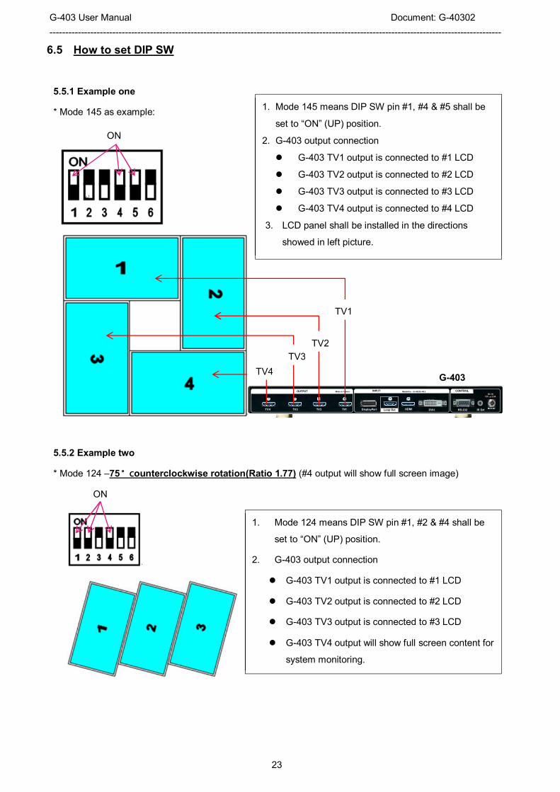
6.5 How to set DIP SW
5.5.1 Example one
* Mode 145 as example:
VGA IN
DC IN
12V 2.0A
DisplayPort DVI-ITV2TV4 RS-232TV3 TV1
OUTPUT INPUT CONTROL
IR Ext
Model N o : G-402/G -403Made in Taiwan
HDMILoop Out
5.5.2 Example two
* Mode 124 –75〫counterclockwise rotation(Ratio 1.77) (#4 output will show full screen image)
ON
ON
TV1
TV2
TV3
TV4 G-403
1. Mode 145 means DIP SW pin #1, #4 & #5 shall be
set to “ON” (UP) position.
2. G-403 output connection
� G-403 TV1 output is connected to #1 LCD
� G-403 TV2 output is connected to #2 LCD
� G-403 TV3 output is connected to #3 LCD
� G-403 TV4 output is connected to #4 LCD
3. LCD panel shall be installed in the directions
showed in left picture.
1. Mode 124 means DIP SW pin #1, #2 & #4 shall be
set to “ON” (UP) position.
2. G-403 output connection
� G-403 TV1 output is connected to #1 LCD
� G-403 TV2 output is connected to #2 LCD
� G-403 TV3 output is connected to #3 LCD
� G-403 TV4 output will show full screen content for
system monitoring.

G-403 User Manual Document: G-40302
------------------------------------------------------------------------------------------------------------------------------------------------
24
5.5.3 Example three
* Mode 06A – 1x3 (Ratio 1.69)
(Please apply 90〫rotation image content to get normal viewing angle. If the content is not at 90〫rotation,
then user needs to create custom mode or rotate the image from [Orientation] menu setting)
6.6 Signal source output resolution selection
Video signal resolution setting will affect final video quality. Please follow below recommendation to set
signal source output resolution.
6.6.1 Basic concept for video source output resolution settings
a. Horizontal direction: If only single unit is required in horizontal direction, please set the horizontal
output resolution at 1920. If multiple units of G-403 are required in horizontal cascade direction,
then please set the horizontal output resolution at 3840.
b. Vertical direction: If only single unit is required in vertical direction, please set the vertical output
resolution at 1080. If multiple units of G-403 are required in vertical cascade direction, please set the
vertical output resolution at 2160.
6.6.2 Example for input resolution settings:
a. When using single G-403, please apply 1920x1080 @60Hz input resolution.
b. For dual G-403 horizontal cascade, please set 3840x1080 @60Hz as input resolution.
c. For dual G-403 vertical cascade, please set 1920x2160 @60Hz as input resolution
d. For 2x2 four G-403 cascades, 3840x2160 @30Hz input resolution will get the best video quality.
e. If signal content is 4k resolution and the player can support 4k playback, please select 4k/2k EDID
to get the best video quality.
f. For more complicated cascade, please follow the instruction in another section in this manual.
6.6.3 How to set preferred input timing resolution in G-403
a. Please change the input resolution by [Option]� [Settings]� [EDID] setting.
1. Mode 06A means DIP SW pin #6 shall be set to “ON” position.
2. “A” means this mode is only be achieved by rotating the image from
signal source. If the image is not rotated from signal source, then it is
necessary to rotate the image by G-403 through [Orientation] menu.
Please also pay attention to content aspect ratio.
3. G-403 output connection
� G-403 TV1 output is connected to #1 LCD
� G-403 TV2 output is connected to #2 LCD
� G-403 TV3 output is connected to #3 LCD
� G-403 TV4 will show full screen image same as signal source.

G-403 User Manual Document: G-40302
------------------------------------------------------------------------------------------------------------------------------------------------
25
b. If the required resolution is not standard VESA standard timing, user may need to set the output
resolution from PC.
c. Please confirm the setting result by [INFO] menu from OSD or IR remote controller.
7 G-403 Application case study
6.1 Preset mode: Mode 145
6.2 Preset mode: Mode 00
1. Install LCD following the directions in drawing.
2. Select [Main Input] DIP SW.
3. DIP SW #1, #4 & #5 pins in [Display Mode] are
set at “ON” (UP) position.
4. Connect G-403 outputs to related LCD
a. TV1 to #1 LCD
b. TV2 to #2 LCD
c. TV3 to #3 LCD
d. TV4 to #4 LCD
5. To check if Bezel compensation is required or
not. If yes, please enable “Bezel”
compensation DIP SW.
6. If PIP is required, select DIP SW in [PIP Input],
[PIP Mode], and [PIP Size & Location].
After finishing DIP SW setting, Power OFF and ON
again is required to execute the command in DIP
SW setting in G-403.
1. Select [Main Input] DIP SW.
2. All DIP SW pins in [Display Mode] are set at
“OFF” position.
3. All outputs will have the same contents
as input source. It becomes 3x in / 4x out
video converter and switcher.
4. If PIP is required, please select DIP SW in
[PIP Input], [PIP Mode], and [PIP Size &
Location].
TV
2
TV4
TV
3
TV1

G-403 User Manual Document: G-40302
------------------------------------------------------------------------------------------------------------------------------------------------
26
6.3 Preset mode: Mode 01
6.4 Preset mode: Mode 03
1. Select [Main Input] DIP SW.
2. [Display Mode] DIP SW #1 is set at “ON”
position. It will show 2x2 video wall.
3. Connect G-403 outputs to related LCD
a. TV1 to #1 LCD
b. TV2 to #2 LCD
c. TV3 to #3 LCD
d. TV4 to #4 LCD
4. To check if Bezel compensation is
required or not. If yes, please enable
“Bezel” compensation DIP SW.
5. User can show dual contents in one 2x2
video wall.
6. To select PIP Input source and set [PIP
Mode] at [POP Full] position, user will get
full screen POP image.
7. User can select [POP Raw] to keep
original aspect ratio in two contents.
8. Power OFF/ON the system again.
TV1 TV2
TV4 TV3
TV1
TV3
TV2
TV4
1. Install TV as showed in the picture.
2. Select [Main Input] DIP SW.
3. [Display Mode] DIP SW #3 is set at “ON”
position.
4. Connect G-403 outputs to related LCD
a. TV1 to #1 LCD
b. TV2 to #2 LCD
c. TV3 to #3 LCD
d. TV4 to #4 LCD
5. To check if Bezel compensation is required
or not. If yes, please enable “Bezel”
compensation DIP SW.
6. Top two TVs are installed at Down Flip
position so that the adjacent edges of
the TVs have the same bezel size.

G-403 User Manual Document: G-40302
------------------------------------------------------------------------------------------------------------------------------------------------
27
7 Multiple G-403 Cascade
7.1 Setup procedures
Multiple G-403 can be cascaded up to 15X15 G-403. Below are the procedures for the setting:
a. Connect signal to 1st G-403, then daisy chain to next G-403. Maximum input resolution is 4K/2K @30Hz.
b. To connect IR receiver extender if necessary.
c. Use IR remote control to execute OSD command.
d. To set Box ID # under [Options]� [Settings]� [Box ID] menu. It is for easy control for each G-403.
� Press “851” on remote controller, only the commands in #1 G-403 can be executed.
� Press “853” on remote controller, only the commands in #3 G-403 can be executed.
� Press “850” on remote controller, the commands can be executed in all G-403 simultaneously.
7.2 Signal source resolution selection
Correct signal source resolution setting will optimize final video quality. Please try different resolution settings
to get the best result. User can select below resolution settings:
Horizontal: 1920 or 3840, Vertical: 1080 or 2160
a、 For single G-403, if signal source is 4K content, to apply 3840x2160@30Hz input resolution will get the
best video quality. If FHD content, please apply FHD input resolution.
b、 For dual G-403 horizontal cascade, 3840x1080 @60Hz will get the best video quality.
c、 For 2x2 four G-403 cascades, 3840x2160 @30Hz input resolution will get the best video quality.
d、 For more complicated cascade, please follow the instruction in below section.
7.3 Case study A: 4k/2k 4x4 video wall
a. Each G-403 will handle one display zone.
b. Connect source signal to all G-403 via daisy chain.
c. Set Display Mode 01 for all G-403.
d. Video wall setting in G-403:
Items Zone A Zone B Zone C Zone D
Zoom H=2, V=2 H=2, V=2 H=2, V=2 H=2, V=2
Pan H=1, V=1 H=2, V=1 H=1, V=2 H=2, V=2
Overlap RH/BTM LH/BTM RH/Top LH/Top
e. If only single signal source is available, please use
HDMI loop out port for daisy chain connection.
f. To fine-tune image position among display zone
A/B/C/D by video wall [Overlap] setting.
g. During [Overlap] adjustment, the image may have
frame tear. It will disappear after power ON again.
h. Save the final setting to OSD [Options] �[Settings]
� [Profile] � [Save] �[Index 1-5]. User can recall
it at any time.
A
C D
B

G-403 User Manual Document: G-40302
------------------------------------------------------------------------------------------------------------------------------------------------
28
7.4 Case study B: 4k/2k 3x3 video wall
a. Select preset display mode: Mode 35/36
b. Connect the same signal to all G-403.
c. Video wall setting in G-403
Items Zone A Zone B Zone C
Zoom H=1, V=3 H=1, V=3 H=1, V=3
Pan H=1, V=1 H=1, V=2 H=1, V=3
Overlap Bottom Top/BTM Top
d. Signal source shall be connected to all G-403 through daisy chain connection.
e. To set overlap pixels to fine tune the image position among each G-403 if necessary.
f. During [Overlap] adjustment, the image may have frame tear. It will disappear after power ON again.
g. Save the setting under [Options]�[Settings]� [Profile]�[Save]�[Index 1~5] menu.
7.5 Case study C: 4k/2k 8x TV irregular video wall
a. Select preset display mode: Mode 126/134
b. Connect the same signal to all G-403.
c. Video wall setting in G-403
Items Zone A Zone B
Zoom H=2, V=1 H=2, V=1
Pan H=1, V=1 H=2, V=1
Overlap RH Edge LH Edge
Overlap pixels for Zone A (Display Unit A) & B (Display Unit B) shall be the same. User can open [Overlap]
menu and select [RH Edge] for A & [LH Edge] for B, then increase the [Overlap] value gradually in both
A
B
C

G-403 User Manual Document: G-40302
------------------------------------------------------------------------------------------------------------------------------------------------
29
[Display Unit A] & [Display Unit B] and will see two images from both G-403 coming closer until the image
edge match together.
d. During [Overlap] adjustment, the image may have frame tear. It will disappear after power ON again
e. Save the setting to [Options] � [Settings] � [Profile] � [Save] � [Index 1-5] menu.
Note:
1. During [Overlap] adjustment, the image may have frame tear because the parameter is just temporary
store in the system. Once the system has been powered OFF/ON again, the settings will be stored into the
system and frame tear phenomenon will disappear permanently and will not happen again.
2. Please enable [Frame Lock] function under [Options]�[Setting] menu to make sure all G-403 will
synchronize with the signal without frame tear or image lag. Default is [Enable].
8 Multiple contents in cascaded display
User can select different input source for Display Unit A & B and set video wall [Zoom] H=1, V=1 in both
G-403 to display different contents in the video wall. It can be saved into another Profile [Index]. User can
switch between different Indexes to show different displays—one content or dual contents in the video wall.
User can use PIP/POP function to add more display content in each display zone. In this case, the maximum
display contents will be up to 4 in the above video wall.
A B X 2
A A B B

G-403 User Manual Document: G-40302
------------------------------------------------------------------------------------------------------------------------------------------------
30
9 Examples for cascaded display
* 2x Mode 35/36, recommended signal source resolution: 1920*2160
* 3x Mode 35/36, recommended signal source resolution: 1920*2160
* 2x Mode 06/12, recommended signal source resolution: 1920*2160
G-403 User Manual Document: G-40302
------------------------------------------------------------------------------------------------------------------------------------------------
31
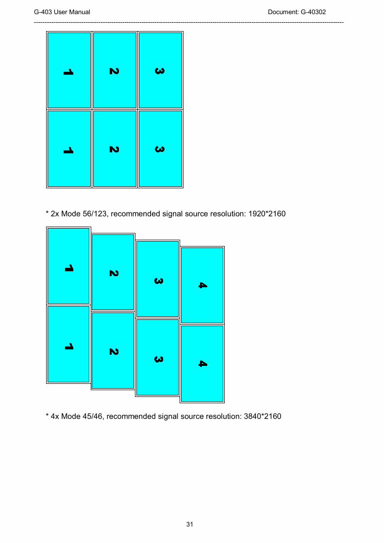
* 2x Mode 56/123, recommended signal source resolution: 1920*2160
* 4x Mode 45/46, recommended signal source resolution: 3840*2160

G-403 User Manual Document: G-40302
------------------------------------------------------------------------------------------------------------------------------------------------
32
* 2x Mode 145/146, recommended signal source resolution: 3840*1080
* 2x Mode 126/134, recommended signal source resolution: 3840*1080

G-403 User Manual Document: G-40302
------------------------------------------------------------------------------------------------------------------------------------------------
33
* 2x Mode 156/234, recommended signal source resolution: 3840*1080

G-403 User Manual Document: G-40302
------------------------------------------------------------------------------------------------------------------------------------------------
34
10 OSD menu and functions
User needs to use IR remote controller to access to the IR receiver on front panel or IR extender connected
to the socket on the back panel to activate OSD menu and functions.
IR remote controller IR Receiver Extender
Important notice:
1. Please set all Dip SW on [Main Input] at OFF position to assign system control authority to OSD
menu so that OSD setting will be executed while the system is powered ON.
2. If any Dip SW in [Main Input] is not at OFF position, when the system is Power ON, the system will
check Dip SW setting first and execute the command in Dip SW setting if the setting is conflicted
with OSD setting. If OSD setting is not conflicted with Dip SW setting, the system will still execute
the settings from OSD or the setting saved in [Profile]
3. After finished OSD operations, please save OSD settings into Profile [Index] for long term
reservation.
4. IR Remote Controller has Shortcut key for Profile [Index] loading function (see below picture).
Profile shortcut key to
load Profile [Index]
� Please set all Dip SW on [Main Input] at OFF position to assign system
control authority to OSD menu settings.
� If user selects input port by Dip SW (at ON position), then when G-403 is
powered ON, the system will follow Dip SW setting to show the image.

G-403 User Manual Document: G-40302
------------------------------------------------------------------------------------------------------------------------------------------------
35
10.1 [Picture] Color Adjustment
10.2 [Image Setup] for PC graphics VGA input
a. Automatic: It will do automatic image alignment inside the system
b. Manual: manual setting for signal Phase and Clock to eliminate image noise in analog input
c. Horizontal Position: to adjust manually the image horizontal position.
d. Vertical Position: to adjust manually the image vertical position.
e. When the input is VGA signal, please connect signal to G-403, then turn on G-403 for image
position auto alignment. After this process, unless user applies other VGA input signal, G-403 will
not do auto alignment again to avoid image shift.
10.3 [Image Properties]
[Image properties] is designed to select image colour temperature, adjust independent RGB colour, select
input port, set display aspect ratio, set PIP setting and image flip/rotation. There are five sub-menus.
[Image Setup] menu can only be activated when
video input is from DVI-I input port with analog
VGA input signal.
Five sub-menus:
� [Color]: Colour temperature selection and
RGB independent adjustment
� [Input Signal]: to select input port
� [Scaling]: to set display aspect ratio, including
POP display mode
� [PIP setting]: to do PIP settings
� [Orientation]: image flip and rotation setting
[Picture] menu is to adjust the color properties for
the entire display unit (4x LCD). It can’t do
individual colour adjustment for each LCD. When
the input signal is in YUV domain, all the items
under menu are free to be accessed. If the input
signal is in RGB domain, only [Brightness] and
[Contrast] can be adjusted. User can do further
separate RGB individual color adjustment under
[Image Properties] menu.

G-403 User Manual Document: G-40302
------------------------------------------------------------------------------------------------------------------------------------------------
36
10.3.1 Color
10.3.2 Scaling
10.3.3 PIP/POP Setting (Picture in Picture & Side by Side)
Picture in Picture (PIP) function is to display two images from one G-403. The maximum size of the
sub-image (PIP) is 1024x768 pixels. The input source for PIP is selectable and can be from any input port of
G-403. The input for main and PIP image can be the same or swapped. The location of the PIP image can be
controlled by OSD menu at any location inside main image. The size of the PIP image is also flexible and can
be controlled by OSD menu as well. Both main and PIP image will go through high end 3D motion
de-interlacing. If a PIP/POP image is required to across multiple G-403, then user can add one GeoBox
G-101 at the front end and connect the output as signal source to G-403.
� Under [Colour] menu:
4 Preset modes for colour temperature
selection
� [Custom]: Independent RGB colour
adjustment. Under this menu, if user select
[Save], then [Picture] menu will be activated for
access
� If user wants to keep PIP setting while system
power on, user needs to set all [Main Input] Dip
SW at OFF position and select input signal by
OSD menu.
� Dip SW PIP/POP setting has only preset image
sizes and positions.
� POP image aspect ratio shall be determined
from [Scaling] menu.
� [Full Screen]:
To fit source image for full screen display
� [Original AR]
To display source image with the same aspect
ratio as source image
� The setting will also affect POP image display
with full screen or original aspect ratio.

G-403 User Manual Document: G-40302
------------------------------------------------------------------------------------------------------------------------------------------------
37
� Display: Under Display menu, there are three items:
� Disable: to Disable PIP or POP function
� PIP: to select PIP display function
PIP (Picture in Picture) mode
� POP: to select POP (side by side) display mode. User can select maintain original image aspect ratio or
full screen mode through [Scaling] OSD menu under [Image properties]. If user set the system
through Dip SW, user can select [POP Raw] and [POP Full] directly from front panel.
(“POP” display mode with original aspect ratio) (“POP” display mode with full screen mode)
�
� Size: (Only apply to PIP function)
� The size of the PIP image can be adjusted though [Size] OSD menu pixel by pixel.
� The maximum size of PIP image is 1024x768 pixels.
� Position: (only apply to PIP function)
� The position of PIP image can be adjusted through Position OSD menu
� The PIP image will be maintained inside main image and can’t be outside main image.
� Pixel by Pixel PIP image position adjustment can be implemented by continuously Horizontal and
Vertical position adjustments.
� Ratio: Aspect Ratio of the display image. (Only apply to PIP function)
� Full Screen: the same aspect ratio as main image or
Five sub-menus under [PIP setting] menu,
--Display: enable PIP or POP
--Size: set PIP size
--Position: set PIP position
--Ratio: set PIP display aspect ratio
--Source: select input source for PIP/POP

G-403 User Manual Document: G-40302
------------------------------------------------------------------------------------------------------------------------------------------------
38
� Original AR: the same aspect ratio as PIP input source.
� POP image aspect ratio can be adjusted through [Scaling] under [Image Properties] OSD menu.
� Source: User can select the input source for PIP/POP image from all input ports. By selecting different
input ports for Main & PIP/POP images, user can have different combination of the display. User can
save different settings into [Profile] under [Option] menu and recall at any time.
10.3.4 Image Orientation (Flip):
� This image orientation function will be applied to entire display units (4x LCD).
� Major purpose:
-- To create more Display Modes based on Pre-defined Display Modes.
-- To enhance and get more flexibility in multiple G-403 cascade applications.
� Display Mode #5 is preset in G-403
� When user rotate image at 90〫, a new display
mode #05A can be achieved in G-403
� 4x G-403 with Mode #5 with 90〫rotation, user can
get 4x4 video wall display.
� 4x G-403 with Mode #1, can also get 4x4 video wall
without image rotation.
Original preset
Display Mode # 05
After 90〫〫〫〫rotation
Display Mode # 05A

G-403 User Manual Document: G-40302
------------------------------------------------------------------------------------------------------------------------------------------------
39
10.4 Video Wall Setting
The purpose for Video Wall Setting is output mode selection, custom mode creation and cascade with multiple
G-403 to become one video wall display. It consists below functions:
� [Output Mode]: To show display modes on OSD for easy display mode selection.
� [Manual Mode]: To create any type of display modes by user.
� [Zoom]: To split source image into different section for each G-403.
� [Pan]: to assign each image section to each G-403 at the right location.
� [Overlap]: to adjust each image section at the right location in cascade application to become a large
video wall display.
� The maximum video wall can be up to 15x15=225 G-403. If each G-403 is connected with 4x LCDs, then
theoretically maximum number of LCD displays can be up to 30x30=900 LCDs from single signal source.
10.4.1 [Output mode]
[Output mode] is for the selection of pre-defined modes in G-403.
1 2
3 4
1 1
1 2
2 2
3 3
3 4
4 4

G-403 User Manual Document: G-40302
------------------------------------------------------------------------------------------------------------------------------------------------
40
10.4.2 [Manual Mode]—To create custom display modes
The purpose for [Manual Mode] is to let user create any type of display mode as he wants. Here is the
structure and concept:
� User can create 10 different display modes and save in [Index 1-10].
� Each Index consists up to 4 LCD—[TV1]~[TV4].
� User can input two parameters (Top Left and Top Right corners coordinates) to get the display location
for each TV (LCD).
� User can execute looping playback of display modes (Index) by selecting the Index and time interval
through [Loop] menu.
� User can adjust Horizontal and Vertical aspect ratio randomly through [Ratio] menu.
� User can shift the image location inside the video wall horizontally and vertically through [Shift] menu.
10.4.2.1 To select custom mode location
10.4.2.2 To set image location for each LCD
� After select display mode, the mode # will
be showed up at the bottom of OSD.
� User can set the same display mode # by
Dip SW to get the same display mode.
1. Under [Manual Mode], there are 5 [Index]
menu and [Loop] menu.
2. Each [Index] represents one display mode
created by user.
3. User can apply different input source and
resolution without affecting display mode
settings.
1. Each [Index] has 4 LCD (TV1 ~TV4)
menus for user to assign image location.
2. [Ratio] is to do further adjustment in
aspect ratio and position shift in entire
display (4x LCD at the same time).
3. [Reset] is to reset all the settings in [TV1]
~ [TV4].

G-403 User Manual Document: G-40302
------------------------------------------------------------------------------------------------------------------------------------------------
41
10.4.2.3 To adjust custom mode aspect ratio and position--[Ratio]
Note: User can also adjust image aspect ratio for entire video wall [Overlap] settings. User can easily Zoom In
(enlarge) the image by reducing image capture range. If user wants to increase the capture range (Zoom Out),
it depends on how many image pixel in image borders. Sometimes, it is limited to only few lines.
1. Inside each [TV], user needs to input
coordinates of [Top Left] and [Top Right]
corners to decide the image location.
2. Total 8 coordinates required for one
complete video wall with 4 LCD.
3. [Position] allows user to do further
adjustment in H&V position of the image in
each LCD without affecting original size and
display angle settings.
4. [Reset] will reset the coordinates to default
settings in current [TV] setting.
5. User can manually input the coordinates for
[Top Left] and [Top Right] corners through
OSD menu direction keys.
� Under [Ratio] menu, user can adjust entire
image display aspect ratio and shift the
image position across entire video wall (4
LCD) at the same time.
� The display aspect ratio adjust range is
from 25% to 200%. The result is similar to
image [Zoom In] & [Zoom Out].
� GAlign PC tool is also available to input the
coordinates for 4 LCDs (TV1~TV4). User
needs to connect PC with G-403 through
RS232 port on back panel.
� After input coordinates, user can select
[Index] and click [Write] to save the settings.
� Please see more details in [GAlign PC Tool]
section.

G-403 User Manual Document: G-40302
------------------------------------------------------------------------------------------------------------------------------------------------
42
10.4.2.3.1 Horizontal [Ratio] adjustment
(100% Horizontal Ratio) (50% Horizontal Ratio)
(200% Horizontal Ratio)
10.4.2.3.2 Vertical [Ratio] adjustment
1. Three item under [Ratio] menu:
[Ratio [Position] & [Reset]
2. Four menus can work at the same time.
1. This function can execute Image Zoom In
& Zoom Out to change the aspect ratio in
Horizontal direction by R/L direction keys.
2. The aspect ratio adjusting range is from
50% to 200%.
3. This function will apply to entire video wall.

G-403 User Manual Document: G-40302
------------------------------------------------------------------------------------------------------------------------------------------------
43
(50% Vertical Ratio) (200% Vertical Ratio)
10.4.2.3.3 Horizontal [Position] adjustment
Note:
The position shifting range is as following:
a. Maximum shift range is inside input video content.
b. If image is ZOOM IN to 200%, image can be shifted up to video wall center line—half image is missing.
(see below)
c. If image is ZOOM OUT to 50%, the image can be shifted up to video wall center line—half image is
blank. (see below)
(200% Horizontal Ratio) (Max. shift to right) (Max. shift to left)
1. This function can execute Image Zoom In
& Zoom Out to change the aspect ratio in
vertical direction by Up/Down keys.
2. The aspect ratio adjusting range is from
50% to 200%.
3. This function will apply to entire video wall.
1. Image horizontal position shift can be
executed by R/L direction keys.
2. Horizontal adjusting range will depend on
the change in Horizontal [Ratio]
3. No image shift is possible if Horizontal
[Ratio] doesn’t change.
4. This function will apply to entire video wall.

G-403 User Manual Document: G-40302
------------------------------------------------------------------------------------------------------------------------------------------------
44
(50% Horizontal Ratio) (Max. shift to left) (Max. shift to right)
10.4.2.3.4 Vertical [Position] adjustment
(200% Vertical Ratio) (Max. shift to Top) (Max. shift to Bottom)
(50% Vertical Ratio) (Max. shift to Top) (Max. shift to Bottom)
Note: By the combination of aspect ratio change and position shift, user can remove image black border or
select special region of the image to highlight (pop up) specific content to attract audience.
[Reset]: will rest the setting in [Ratio] and [Position] settings to default value.
10.4.2.4 [Loop]—Looping playback and protect LCD from burn-in mark
a. User can create up to five different playback modes (Index) and looping playback under preset time
interval. This function can be used to highlight different products from the same image content without
PC system. For instance, if one content consists of 4 products. User can display all products in Index
one, then pop-up product A in Index 2, product B in Index 3, product C in Index 4 and product D in
1. Image vertical position shift can be
executed by Up/Down direction keys.
2. Vertical range will depend on the change
in Vertical [Ratio]
3. No image shift is possible if Vertical [Ratio]
doesn’t change.
4. This function will apply to entire video wall.

G-403 User Manual Document: G-40302
------------------------------------------------------------------------------------------------------------------------------------------------
45
index 5. After set looping playback, user will see advertisement for complete image, then highlight
each product at specific LCD in sequential order. User can see some demo video in the website to get
another display idea.
b. User can select the playback modes (Index) and time interval from OSD.
c. User can input two same Index to double the display interval time for this Index.
d. Please locate the looping display modes starting from Index 1. User can only select total number of
looping playback mode starting from #1. If select “3”, then only Index 1-3 can be looped in.
e. This function can be applied to create different playback mode (Index) at slightly position shift and
apply looping playback function to prevent from burn-in mark on the LCD to extend the life time. This
is important for the display with still image on the content.
Looping playback is only functional for [Index
1-Index 10] under [Manual Mode]. It is nothing
to do with Index under [Profile] menu.
1. User can select the Index for looping
playback in [Loop Range].
2. If select “3”, then only Index 1, Index 2 and
Index 3 can be selected for looping
playback.
1. The time interval to switch among different
Index can be set by [Loop Time].
2. The max looping time interval is 10
minutes (600 seconds)
3. User can create different [Index] to
highlight different products from the same
input source.

G-403 User Manual Document: G-40302
------------------------------------------------------------------------------------------------------------------------------------------------
46
10.4.2.5 Procedures to create custom video wall
10.4.2.5.1 Introduction
a、 User can create all kinds of custom display modes for regular, portrait and irregular video wall with
different size, resolution and bezel LCDs at any angle and position through input the coordinates of two
corners in each LCD--Top left and Top Right.
b、 4 LCD as one display unit and can be cascaded without number limitation. The display panel shall be at
16:9 aspect ratio. Different aspect ratio LCD requires customization in factory.
c、 PIP/POP function is still available in the custom modes created by user.
d、 Due to some deviation among different panel brands, even using the same size 16:9 panel, it is still
necessary to check the result and fine-tune image position if necessary.
10.4.2.5.2 Collect coordinates from physical drawing
a、 User can convert physical design drawings into 1920x1080 coordinates and pick up the coordinates at
Top Left and Top Right corners in each LCD active display region, then input to G-403 through OSD or
PC tool to get the result. The original point for the coordinate system is set at Top Left corner as (0, 0).
TV1 TV2
Figure A

G-403 User Manual Document: G-40302
------------------------------------------------------------------------------------------------------------------------------------------------
47
b、 Please note that the coordinate system (16:9) in H&V directions should have the same scaling ratio. In
above example, user can only take horizontal to full scale but the vertical direction remains some
blanking borders. User can put “Video Wall” at the center position or close to one edge. After the video
wall is created, user can use [Ratio] and [Position] function to adjust aspect ratio and final image
position freely.
c、 In above drawing, the coordinates for TV1 and TV2 are as follows:
� TV1 coordinate for Top Left corner=(0, 586),Top Right corner=(366, 216)
� TV2 coordinate for Top Left corner=(815, 635),Top Right corner=(447, 286)
� Please pay attention to the display direction of the TV
10.4.2.5.3 Collect coordinates from photo
User can also take picture of the LCD array and put this photo into a 1920x1080 coordinates system
and collect 8 points of the coordinates for 4x LCD, then input these numbers into G-403. Below are the
processes:
� The photo shall be corrected without distortion. If distortion happens, user can use [RealWorld
Paint] freeware to correction image distortion in advance.
� Use Microsoft Picture Manager to trim the edge of the display area or directly use [Paint] software
to trim the image.
� Resize to 1920x1080 image resolution in JPG or PNG format.
� To view this photo file in Microsoft “Paint” and user can click mouse to capture the coordinates.
Example: 6x LCD video wall with 2x G-403. User can assign any LCD to any G-403 output.
1. To open the photo under [Paint]

G-403 User Manual Document: G-40302
------------------------------------------------------------------------------------------------------------------------------------------------
48
2. Resize the image in the edge to 1080 pixel height or 1920 pixel width and maintain aspect ratio
3. Open [File]� [Properties] and resize the image to 1920x1080 resolution
4. Select [All], then move the image to the center of 1920x1080 coordinates

G-403 User Manual Document: G-40302
------------------------------------------------------------------------------------------------------------------------------------------------
49
5. Click Top Left and Top Right corner for each LCD to collect the coordinates for each LCD. User can
enlarge the display scale to get more accurate result.
6. Use GAlign PC tool to input coordinates for each G-403
7. To do some position fine-tune if necessary.
10.4.2.5.4 Upload coordinates into G-403 via OSD menu
� After collect coordinates for all LCD, user can upload the coordinated into G-403 though OSD.

G-403 User Manual Document: G-40302
------------------------------------------------------------------------------------------------------------------------------------------------
50
� Example to store custom mode in Index 2:
[Video wall]� [Manual Mode]� [Index 2]
� Select [TV1]� Select [Top Left/Top Right]� Slide bar to input Coordinates� TV1 Done
Back to select [TV2]� Select [Top Left/Top Right]� Slide bar to input Coordinates� TV2 Done
Next step is to execute the same procedures for TV3 & TV4.
� User may have some difficulty to see the OSD to set Coordinates. The best way is to use GAlign
PC tool to upload coordinates.
10.4.2.5.5 Upload coordinates into G-403 via [GAlign] PC tool
� Above is PC tool (GAlign) for user to load coordinates of each LCD through RS232 port. Please
select [Index] and press [Write] after key-in all coordinates. It will be convenient while user has
difficulty to see OSD for manual upload. The result will be the same as manual upload via OSD.
� User can also set H&V aspect ratio and position shift through [Warp Ratio] and [Warp Position].
� GAlign can read back the settings on the screen and modify in PC. This is good for the
application while user can’t see the OSD manual on the screen due to irregular arrangement.
� Another important application for [Read] function is to read back one Index setting and do
slightly modification, then save to the 2nd
Index. When user want to set up image to prevent from
Burn-in Mark on the LCD, user can use the same way to create several Indexes for looping
playback.
� User can read back the data from one G-403, then apply to another G-403.
10.4.2.5.6 Create custom mode in multiple units cascade
a、 If the signal source is 1920x1080 or less, then take a picture or make drawing for complete video
wall similar to [Figure A] as showed in section 10.4.6.2. Assign 4 LCD for one G-403 and the rest
LCD for another G-403. Follow the same procedures as described in previous section to collect
coordinates for each LCD and input to G-403 to get the display that you need. The system can
still support input resolution higher than FHD
b、 If the signal source is more than FHD and user wants to use higher signal input resolution. User
needs to split the image into several sections in FHD size to cover the LCD display range in each

G-403 User Manual Document: G-40302
------------------------------------------------------------------------------------------------------------------------------------------------
51
G-403. After finish the assignment, user needs to do further [Video Wall] settings to split the
signal source for each G-403 (ZOOM), assign image location (PAN) and adjust image positions
(OVERLAP) so that adjacent G-403 image can match together. All of the operations can be done
via OSD menu under [Video Wall].
Below picture is to show a video wall designed with 4x G-403 together with 15x LG 55” LCD modules. User
can take pictures after LCD installation, then to collect two coordinates for each LCD and input the data to
G-403 by GAlign PC tool. User may need to do some position fine tune through adjusting the coordinate due
to some distortion of the picture.
10.4.2.5.7 Create custom modes in portrait display
If the display is at portrait position, user can apply the same procedures as above to build the video wall. User
can also rotate the video wall at 90/270 degrees and collect the coordinates to build the system to get higher
input resolution and better video quality. After installation, user needs to apply 90/270 degrees rotated
content to get correct display angle.

G-403 User Manual Document: G-40302
------------------------------------------------------------------------------------------------------------------------------------------------
52
10.4.2.5.8 Image position fine-tune
a、 Please apply video wall test pattern and check if further position adjustment is required or not. Please
download from our website.
b、 For simple video wall array, user can use OSD to change Top Left and Top Right coordinates to do fine
tune. For large video wall or irregular array, user may not see the OSD. It will be more convenient and
easier to use GAlign PC tool for image position fine-tune. Please apply [Real Time] mode in GAlign tool
so that user can see the real time position change for easy alignment.
c、 User can use new RC-700 remote controller to access Top Left/Top Right menu for each LCD and
adjust image position even without seeing OSD menu.
d、 Please figure out the relation among 4 corners in a screen with 16:9 aspect ratio. If one corner is fixed,
and change the position in the second corner, the image position and size will be also changed to show
a new image in 16:9 aspect ratio.
e、 OSD [Position] next to [Top Right] coordinate input menu can adjust the image position for each LCD at
H&V direction without change the rotation angle and size of the image. It is convenient for position
fine-tune adjustment.
f、 User needs to save the settings into [Option]� [Settings]� [Profile]� [Save]� [Index].
10.4.2.5.9 Video player operation issue
a、 In some case, user may be difficult to see the operation menu of signal source.
b、 The best way is to set video player with “Auto-Run” so that end user can power on the signal source
and automatically playback. G-403 can auto power on/off according to the input signal detecting.
c、 If no auto-run function in video player, user can connect one monitor to the last G-403 loop out port as
monitoring devices for easy video source playback operation.
d、 If user can see OSD menu, user can select different [Index] or to select different display mode under
[Video Wall] � [Output Mode] menu to display full screen content in each LCD. After set video source,
then turn back to required Index.
e、 User can also set input dip SW manually and turn off/on the system again to get four independent full
screen displays for user to do further signal source operation.
f、 After signal source can normally playback, user can recall Profile Index by [Profile] shortcut key in
remote controller to get final result.

G-403 User Manual Document: G-40302
------------------------------------------------------------------------------------------------------------------------------------------------
53
10.4.3 Zoom: split image for each G-403 in cascade application
� User can set both Horizontal and Vertical Zoom value based on the array of the Display Units. In below
example, each number means one Display Units (4 LCDs) and also means one G-403.
Example A:
� � �
Example B:
� � �
� � �
� �
10.4.4 Pan: assign image location to each G-403 in cascade application
� [Pan] is to assign the split image location
for each Display Unit.
� Horizontal value is calculated from LH to
RH direction and Vertical value is
calculated from top to bottom.
� User needs to set H & V [Pan] value to
assign the image location for each G-403
to build a large video wall display.
3x1 G-403 horizontal cascade:
--Horizontal Zoom=3
--Vertical zoom=1
� G-403 is designed with 4 LCDs as one
Display Unit
� Zoom function is to split the source image
content for different Display Unit in multiple
G-403 cascade applications.
In 3x3 G-403 cascade:
--Horizontal Zoom=3
--Vertical Zoom=3
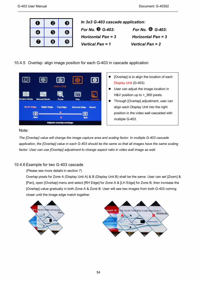
G-403 User Manual Document: G-40302
------------------------------------------------------------------------------------------------------------------------------------------------
54
� � �
� � �
� �
10.4.5 Overlap: align image position for each G-403 in cascade application
Note:
The [Overlap] value will change the image capture area and scaling factor. In multiple G-403 cascade
application, the [Overlap] value in each G-403 should be the same so that all images have the same scaling
factor. User can use [Overlap] adjustment to change aspect ratio in video wall image as well.
10.4.6 Example for two G-403 cascade
(Please see more details in section 7)
Overlap pixels for Zone A (Display Unit A) & B (Display Unit B) shall be the same. User can set [Zoom] &
[Pan], open [Overlap] menu and select [RH Edge] for Zone A & [LH Edge] for Zone B, then increase the
[Overlap] value gradually in both Zone A & Zone B. User will see two images from both G-403 coming
closer until the image edge match together.
� [Overlap] is to align the location of each
Display Unit (G-403)
� User can adjust the image location in
H&V position up to +_900 pixels.
� Through [Overlap] adjustment, user can
align each Display Unit into the right
position in the video wall cascaded with
multiple G-403.
In 3x3 G-403 cascade application:
For No. � G-403: For No. � G-403:
Horizontal Pan = 3 Horizontal Pan = 3
Vertical Pan = 1 Vertical Pan = 2
A B

G-403 User Manual Document: G-40302
------------------------------------------------------------------------------------------------------------------------------------------------
55
[Options]: OSD Miscellaneous Functions
10.5.1 [Information]: System Information
10.5.2 [Language]: OSD Language
10.5.3 [Reset]
Five sub-menu under [Options]:
- [Information]
- [Language]
- [Reset]
- [Accessibility]
- [Setting]
[Information] menu shows the following
information in GeoBox, such as Input mode,
output mode, Network status, Model name and
Firmware version.
Two types of Reset can be done: Reset All &
reset Video Wall.
� [Reset All] will reset all user settings but the
settings stored in [Index] under [Manual
Mode] and [Profile] will not be deleted.
� Reset [Video Wall] will reset the settings in
Video Wall function to factory default.
Three OSD menu languages can be selected:
English, Simplified Chinese and Traditional
Chinese

G-403 User Manual Document: G-40302
------------------------------------------------------------------------------------------------------------------------------------------------
56
10.5.4 [Accessibility]
10.5.4.1 [Button Repeat Rate]
10.5.4.2 [Menu Time Out]
� When [Off] is selected, the OSD menu will remain in the screen until user activates other OSD
function or input/output mode change.
Four sub-menu under [Accessibility]:
� OSD [Button Repeat Rate]
� OSD [Menu Time out]
� Splash screen [Logo Time Out]
� No signal input [Standby time out]
OSD [Button Repeat Rate]:
It controls OSD button response speed while
user presses OSD button continuously.
OSD [Menu Time Out]
� OSD menu will disappear from the screen
based on time setting.
� The default time is 30 seconds.
� [OSD Time Out] shortcut key is available on
IR remote controller

G-403 User Manual Document: G-40302
------------------------------------------------------------------------------------------------------------------------------------------------
57
10.5.4.3 [Logo Time Out]
10.5.4.4 [Standby Time Out]
10.5.5 [Setting]
10.5.5.1 Audio [Mute]
Five sub-menu under [Setting] menu:
� [Mute] Audio mute or enable
� [Frame Lock]: system synchronization
� [Box ID]: Set control ID
� [Profile]: Save profile settings
� [Network]: set RS232 and network control
Audio Mute:
� [Mute Off] will enable audio output.
� [Mute On] will disable audio output.
� [Mute] hot key in remote controller is
available
� To set the time to show Splash screen.
� If zero is selected, then the splash screen
will not be showed during system booting
up period. It will reduce the boot up time.
The default setting for [Standby Time Out]
is “0” seconds. The time can be set by user.
If the time is set to “60”, then G-403 will turn
off the output signal after 60 seconds when
no input signal is detected. If the LCD has
the same function, user can power on/off
the system through input source signal
control.

G-403 User Manual Document: G-40302
------------------------------------------------------------------------------------------------------------------------------------------------
58
10.5.5.2 Frame Lock and Free Run Mode
[Frame Lock] will ensure the input and output frame rate synchronize together. This is mainly for
multiple G-403 applications. If [Flame Lock] is disabled, the system will be in [Free Run] mode and
keeps continuous output timing. This will provide quicker input source or input timing change under
below conditions:
� Input signal shall have the same refresh rate (i.e. 60Hz)
� No HDCP compliant signal.
It is possible to see frame tear artifact if [Frame lock] is turned off.
10.5.5.3 [Box ID]
10.5.5.4 [Profile] Setting
[Box ID] is identification # in each G-403 for
individual RS232 or IR remote control.
� GeoBox ID No is from 1-99
� After set Box ID, user can control GeoBox
individually via IR Remote controller,
RS232 & Ethernet
� IR control ID # is from 0-9 only.
� [Profile] is to save and load user settings
� If the settings saved in [Profile] are
conflicted with Dip SW setting, Dip SW
setting will be executed. If user wants to
show [Profile] setting when turn on the
system, please set [Main Input] at off
(down) position.

G-403 User Manual Document: G-40302
------------------------------------------------------------------------------------------------------------------------------------------------
59
Application example: when cascade with two G-403, user can set below display patterns:
1. To show cascade image with single content across whole video wall.
2. To show two side by side contents across whole video wall.
3. To show one PIP content in cascaded image.
4. To show two PIP contents in cascaded image.
User can save these different display patterns in G-403 and recall them by RS232 or remote controller.
Please note:
� When execute system reset, Profile settings will remain the same without change.
� If the settings in Dip SW on the front panel are different from the settings in [Profile], Dip SW setting will
have the 1st priority. For example, if your Dip SW selects Display mode # 02 and you select mode #05 via
OSD. Once you power OFF/ON the system again, it will show mode #02 but not mode #05. The same
issue will happen in PIP/POP settings, if you select a position and size of PIP image by OSD menu, once
you power OFF/ON the system, it will follow the setting in Dip SW but not OSD. You need to load the
profile to get new OSD settings.
10.5.5.5 [Network]
Five Indexes can be chosen to save G-403
settings and recalled by IR remote controller
or RS232 through [Load] menu under
[Profile]
� Only RS232 under this Menu.
� User can use external UART to Ethernet
converter to control G-403 through
Ethernet control system.
� User can use simple button type RS232
controller to switch among different
Profile settings.

G-403 User Manual Document: G-40302
------------------------------------------------------------------------------------------------------------------------------------------------
60
10.5.5.5.1 RS232 setting:
a. Serial port setup
b. Terminal setup

G-403 User Manual Document: G-40302
------------------------------------------------------------------------------------------------------------------------------------------------
61
10.5.5.5.2 Example of low cost RS232 controller
10.5.5.6 [EDID] setting
Selective EDID setting is added into G-403. The purpose are as follows:
c. G-403 can support big range of input signal timing—from SVGA up to 4k/2k. In order to get the best
video performance, user needs to select different input signal resolution.
d. Different PC display cards have different setting and behavier. Many users may not be able to do
the right settings
e. High end media player or server can support big range of outputs—from 720p to 4k/2k. If no EDID
selection function, only one default EDID can be selected by media player. The system may not
show the best video wall output quality.
f. Different display modes may show different final image aspect ratio. User can ultilize different EDID
setting to change input signal timing and get different output aspect ratio.
� Activate EDID setting menu:
[Options]� [Setting]� [EDID]
� Use IR remote controller to select
desired EDID.
� After select EDID, the PC or medial will
automatically change the output timing
setting.
� Press [INFO] key to check if the input
and output timing are set correctly.
� User can save up to 5 settings into [Profile].
� User can connect this RS232 controller with each
G-403 through RS232 cable in parallel.
� Click Profile button in RS232 controller to power
on/off the system or select display Profile.
� If separate RS232 control is required, user needs to
set different [Box ID] for each G-403 and put ID #
into RS232 command.

G-403 User Manual Document: G-40302
------------------------------------------------------------------------------------------------------------------------------------------------
62
� In very rare cases, some PC may not follow the EDID settings from G-403 and show different result. If
it happens, please open PC resolution setting window and select desired output resolution from PC.
� If user selects GeoBox as display device, user can choose PC output resolution up to the maximum
resolution set by EDID in G-403.
� If user wants to create custom output resolution in PC, user needs to select GeoBox as display device
for further settings. Please select Reduced Blanking timing in high resolution output to reduce the
output clock for easy high speed data connection.
� After user creates custom output resolution in PC, use needs to go back to Resolution Selection
Window in PC to select the desired output timing.
Note: please open GeoBox 2-3 seconds before open signal source so that signal source can detect the EDID
setting in GeoBox and sends out the right timing.
11 PC Tool
11.1 G-403 GAlign PC Tool
11.1.1 G-403 PC tool download and decompress
1. Please download G-403 PC tool from our website.
2. Open [GAlign.7Z] and decompressed the file into [GAlign] directory.
3. [GAlign] directory should consist three files:
� Quick GAlign PC tool user guide for G-403
� GAlign.exe
� UI.INI
4. User can create Language based on his requirement. Please open UI.INI and add new string set into
User can also select EDID manually. The
range will be from 1024x768 to
3840x2160. Based on VESA standard
Horizontal resolution is in a step of 8
pixels and vertical resolution is in 2 pixels.
After creating the EDID, PC or laptop may
still can’t output required timings due to
hardware limitation or driver issue. In
some case, user also needs to do some
manual selection of the output resolution
is display output settings.

G-403 User Manual Document: G-40302
------------------------------------------------------------------------------------------------------------------------------------------------
63
UI.INI and save this modification inside the same [GAlign] directory. Then user can find a new
language in this PC tool.
5. Turn all Dip SW to OFF position so that the settings in [GAlign] will not be affected by Dip SW settings.
6. Open [GAlign.exe] file and user will see operation window.
7. This PC tool is .exe file and may be blocked by Anti-virus software. Please remove this barrier.
11.1.2 [GAlign] PC tool operation procedures
(1) : Open [GAlign.exe] file. Select Language.
(2) : User should see [COM #] at the top right corner. If not, RS232 is not connected with PC. Please check
[Device Manager] in PC and make sure RS232 USB driver is correctly installed. Click [Connect], user
will see [Close] in the block. It means PC tool has already connected with G-403 and ready to use.
(3) : Select [Index 1-5]. Index is the location to store your settings.
(4) : Click [Diagram] will enable a diagram of the draft drawing of the image for each TV.
(5) : key-in the coordinates of Top Left corner and Top Right corner for TV1 which user captures from
picture or layout plan file.
(6) : Click [Write] button. User should see the result in TV1.
(7) : follow the same procedures to key-in coordinates for TV2-TV4. Then to click [Write] button to see the
result.
(8) : If the position of the image is still not accurate, please disable [Diagram] and click [Real Time] button to
enable real time image position adjustment. When user click the slide bar in each coordinate, user will
see the image change in real time. After finish position fine-tune, please click [Write] button again to
save your final result.
(9) : [Warp Ratio] is to adjust aspect ratio (image width and height) for the complete image in horizontal and
vertical directions.
(10) : [Warp Position] is to adjust complete image position in the video wall in horizontal and vertical
directions. No position can be shifted before user adjusts the [Warp Ratio].
(11) : [Profile] is to save all settings inside G-403 including input source, PIP/POP, video wall settings, ratio,
looping playback, color... Please select Profile # and click [Save] to store the setting and click [Load] to
1
3 7
5
6
8
10
2
11
9
12
4
13
14 15

G-403 User Manual Document: G-40302
------------------------------------------------------------------------------------------------------------------------------------------------
64
recall it at any time. Maximum up to 5 Profiles can be saved.
(12) : [Loop Range] is to select the Index quantity for looping playback. Please put the Index for playback at
the front. User can only set the quantity for playback starting from the 1st Index.
(13) : [Loop Time] is to set the time interval for looping playback.
(14) : [Read] is to read back current setting inside G-403 and do further modification or [Write] to another
Index. It is convenient to create different loop playback index for LCD protection or flexible display
(15) : [Reset] is to reset the setting to default value.
11.2 GPM (GeoBox Parameter Manager) system setting backup Tool
11.2.1 Purpose:
This GPM (GeoBox parameter Manager) tool is for user to save GeoBox settings in PC as backup. The data
can be restored or copied to other unit with the same model. Once a new unit replacement is required, user
can restore the settings to new unit and get the same result. The parameter can also be copied to other unit
for similar project to reduce the time for the setup. Please download GPM backup tool from our website.
11.2.2 GPM installation:
1. Decompressed the attached [GPM.7Z] file with RAR, 7Z or WinZip.
2. The password for the decompression is “VNS” if required.
3. Execute [GPM.exe] and user will see below operation window and show up COM#.
4. GPM.exe program may be locked by Windows or anti-virus software. Please select [Accept] to
continuously run this software.

G-403 User Manual Document: G-40302
------------------------------------------------------------------------------------------------------------------------------------------------
65
11.2.3 System connection:
Please connect GeoBox and PC with RS232 cable. User needs to install driver for USB to RS232 cable.
Once the system is connected, user will see [COM #] in the window and GPM is ready to be used.
11.2.4 Instruction:
1. Data types to be stored.
i. Data inside [Profile] settings, including all settings from Index-1 to Index 5. (Default)
ii. All data inside EEPROM (including Profile setting data).
2. If user didn’t CHECK [Profile only] and click [Backup], GPM will save all the data inside EEPROM with
xxx.GED file name. The saved data include [Profile] settings and all other data inside EEPROM.
3. When user [Restore] the data to GeoBox, the Firmware CODE VERSION in GeoBox should be the
same and with the same CHECK SUM. Otherwise, it can’t be restored and the unit will be reset all the
data to default value.
4. Please click [Restore] and browser xxx.GED file to load back to GeoBox.
5. When user select [Profile Only] as shown above and clip [Backup], GPM will only store the data inside
[Profile] with xxx.GPD file name. It means user needs to save all the settings into [Options]�
[Settings]� [Profile]� [Save]� [Index 1-5]. GPM will only save all the data inside [Profile] from Index
1-Index 5.
6. When user wants to restore xxx.GPD data back to GeoBox, please CHECK [Profile only] and click
[Restore] button, browse xxx.GPD file and load it into GeoBox.
7. GPM can't identify GeoBox model now. To restore different model parameter will cause system reset
all data to default.
8. GeoBox will auto reset after restore the parameter.
9. The time to save the data will take about 60-120 seconds.
10. We propose user to save all the settings data into [Profile], then to use [Profile only] function to backup
all the settings. [Profile Only] allows user to restore the data in different code version.
Important Notice:
a、 If the FW version with structure change in OSD, then even [Profile Only] backup data is not able to
be Restored.
b、 Please save file into GeoBox Profile menu with signal connected to GeoBox. In old version firmware,
when no input source is connected to GeoBox, the backup data will not include color setting data
and user may only see black image with RGB color value set to “0” after data Restore.