future irrigation based on solar tracking...
TRANSCRIPT

IOSR Journal of Electrical and Electronics Engineering (IOSRJEEE)
ISSN: 2278-1676 Volume 1, Issue 3 (July-Aug. 2012), PP 12-25 www.iosrjournals.org
www.iosrjournals.org 12 | Page
Future Irrigation Based On Solar Tracking System
Mr.S.Mathankumar1, Ms.V.Agalya
2 IEEE Member, Mr.P.Loganathan
3
Assistant Professor1,3, Department of EEE,V.M.K.V.Engineering.College,Salem-636308.Tamil nadu(st),India.
Assistant Professor2, Department of EEE, Mahendra Engineering. College, Mallasamudram-637503.Tamil
nadu(st),India
Abstract: A village will be deemed to be electrified if the electricity is used in the inhabited locality, within the
revenue boundary of the village for any purpose whatsoever .But with the prevailing crisis of electricity when
we are not able to provide electricity to even the urban house hold despite the fact that the most of the urban population is prepared to pay for the electricity. Further with the existing availability of power we are not able
to feed the rural consumer with more than 8 hours of electricity then electrifying virgin villages with already
crippling. We do not deny the importance of electricity but the villagers who even after getting the village
electrified and still not getting electricity are more frustrated than the villagers without electrified village. This
directly affect our farmers so as our device will help them to overcome this problem.The Existing method of the
power generation mainly uses petrol and diesel pumps for irrigation purposes that cause high amount of air
pollution and other environmental hazards. The emission of carbon dioxide and sulphur oxides results in
environmental changes and leads to global warming. The environmental changes have become an important
factor to be dealt with as it is an important factor on which the world is concerned about. We are
proposing here deals with the modern technology to eliminate any problem of pollution. In the proposed method
solar tracking system is implemented by replacing the old fossil fuel based generators for pumping water for
irrigation purpose. The solar plates are used to track the maximum amount of solar radiation to convert it into electrical energy. The process is a renewable process and evergreen.
Key words: solar , wind, water pumping, centrifugal pump
I. Introduction 1.1 PROLOGUE
India is facing an acute energy scarcity which is hampering its industrial and agricultural growth and
economic progress. Setting up of new power plants is inevitably dependent on import of highly volatile fossil fuels. Thus, it is essential to tackle the energy crisis through judicious utilization of abundant the renewable
energy resources, such as solar, wind, bio mass and geo thermal energy. Presently the power crisis is in rural
areas, this power cut directly affect our farmers.
Due to frequent power cut in the village areas such as 3 to 6hrs. Even the most of the rural areas don’t
have the power yet. These farmers are dependent on the rain water for the irrigation. This affects our farmers.
As a result they are not able to irrigate their land .So we can illuminate this problem by DC motor which is
charged by solar , wind power or both as per the renewable sources is suitable to that particular region. This will
make them less dependent on the non-renewable energy like petrol, diesel etc.
1.2 OBJECTIVE OF THE PROJECT
India is heavily dependent on fossil fuels for its energy needs. Most of the power generation is carried
out by coal and mineral oil-based power plants which contribute heavily to greenhouse gases emission. Apart from augmenting the energy supply, renewable resources will help India in mitigating climate change. Energy is
a necessity and sustainable renewable energy is a vital link in industrialization and development of India.
Our main objective is to pump the water by DC Motor using renewable energy like solar and wind to
irrigate the land, pumping the water to house for domestic purpose like drinking, washing, cooking etc. This will
make them less dependent on non renewable energy and they don’t have to pay for the power that is being used
for running the motor pump.As a result the villages where there is no electricity, there they can use these
machines for Irrigation, drinking water, etc. By using this device we can be independent of frequent power cut
in villages.
1.3 SCOPE OF THE PROJECT A village will be deemed to be electrified if the electricity is used in the inhabited locality, within the revenue boundary of the village for any purpose whatsoever .But with the prevailing crisis of electricity when
we are not able to provide electricity to even the urban house hold despite the fact that the most of the urban
population is prepared to pay for the electricity.

Future Irrigation Based On Solar Tracking System
www.iosrjournals.org 13 | Page
Further with the existing availability of power we are not able to feed the rural consumer with more
than 8 hours of electricity then electrifying virgin villages with already crippling infrastructure and excessive
line losses already burdening the electricity tariff for the existing consumer is not a wise step. We do not deny
the importance of electricity but the villagers who even after getting the village electrified and still not getting
electricity are more frustrated than the villagers without electrified village. This directly affect our farmers so as
our device will help them to overcome this problem.
1.4 FUTURE EXTRACTION
The paper is mainly based on the renewable source of energy. The DC source of energy is directly fed
to the centrifugal Pump that reduces effective cost of the project. The project is going to benefit the rural areas
where there is a scarcity of electrical energy. The proposed method of our project can replace the present
method of irrigation that is based on non-renewable source of energy.
1.5 APPLICATIONS
The proposed project can be effectively used in rural areas for generation of electricity for irrigation
purpose.
The generated electricity can be effectively used for commercial purposes as the there are no electricity
supply is not available. The proposed project utilizes the maximum amount of solar energy to convert to electrical energy.
The GSM technology used enables the user to control the pumping system by sending SMS signal from
any part of the world.
1.6 CHAPTER ORGANIZATION
Chapter 1: Deals with general introduction to the problem, review of the work and objectives
Chapter 2: Literature Review
Chapter 3: Conventional Method of Water pumping System
Chapter 4: Proposed Method of Irrigation by PMBLDC Centrifugal PumpUsing Solar Tracking System
Chapter 5: Output Graph
Chapter 6: Conclusion Chapter 7: Reference
II. CHAPTER LITERATURE REVIEW
1. The authors present a photovoltaic powered pump drive scheme comprising a separately excited DC motor
and DC/DC converter. The control strategy ensures maximum solar energy utilization and effective load
control. Economic sizes from 1 kW-30 kW can be utilized. With the advent of separately excited DC
motors it is advantageous to utilize solid state converter DC chopper. The authors present the full unified
model development and control strategy for maximizing solar energy utilization and ensuring maximum
kWh energy used by the pump load. The proposed scheme can be utilized in spray irrigation and
greenhouse water supply management. In addition the authors present the digital simulation model
development, component sizing, PV array switching and tracking controller to ensure online maximum solar energy utilization. Laboratory testing of the drive scheme is also included. J. Rodriguez, J-S. Lai,
and F. Z. Peng, “A photovoltaic powered separately excited DC motor drive for rural/desert pump
irrigation,” Electrical Machines and Drives, 1993. Sixth International Conference on (Conf. Publ. No.
376) , pp. 406, 8-10 Sep 1993.
2 . Meteorological conditions in many sites of the world countries as well as in Egypt are well adapted to install more than one of renewable energy sources (RESs) to supply electrical loads. Solar and wind
energies are the most convenient and economic types of RESs pertaining the Meteorological conditions of
Egypt. Also, the main type of isolated loads at rural and remote areas of Egypt is pumping loads for
irrigation purposes. So, three alternatives of solar photovoltaic and wind energy systems can be used to
supply these loads. In this work, a proposed model has been introduced to evaluate the design and economy
of these alternatives to supply isolated loads in a remote area. This model is used also for optimizing these
alternatives of RESs from economical point of view. The proposed model depends on the Meteorological
data at the installation site, the performance of solar photovoltaic and wind energy systems used, the type
and capacity of energy storage facility employed, the economical parameters of these resources and load.
The proposed model is applied numerically to design three alternative sources of solar photovoltaic and wind energy systems to supply an isolated load in a remote area of Egypt. The economy of these sources are
determined and compared to develop the most economical one of these RESs. G. Carrara, S. Gardella, M.
Marchesoni, R. Salutari, and G. Sciutto, “Design and economy of renewable energy sources to supply

Future Irrigation Based On Solar Tracking System
www.iosrjournals.org 14 | Page
isolated loads at rural and remoate areas of Egypt,” Electricity Distribution - Part 1, 2009. CIRED
2009. 20th International Conference and Exhibition on, pp. 1, 8-11 June 2009.
III. CHAPTER
CONVENTIONAL METHOD
3.1 SYNOPSIS
Energy plays an important role in the material, social and cultural life of man kind. The energy needs
are increasing day by day. This is the result of population growth and increase in the standard of living which is
directly proportional to energy consumption. As we know that man kind will be never lacking in energy. Today, it is liquid fluid, tomorrow it may
be uranium with an element of risk. Risk exists where ever there is human activity and production of energy.
Just as the supply of fossil fuel is finite thus there will be the supply of uranium. Perhaps, uranium would be
exhausted quickly if it is used on a large scale. It is therefore, harnessing the gigantic inexhaustible solar energy
source reduces the dependence on fossil fuels.
Fig 3.1 Solar Water Pumping System
3.2 INTRODUCTION
For the environmental concerned, the solar energy harnessing system offers advantages in that, it emits
no pollutants in to the atmosphere as they are with the combustion of fossil fuels. Thus, as a long term option
solar energy system can be considered as an alternate to all the finite fuel system. Therefore, there is no energy
shortage today nor will there be in the near future?
The lifting of water for drinking or irrigation purposes is of great importance in widely distributed
villages with little or no rural electrification and where under ground water is available. Solar energy is converted to mechanical energy to drive small water pumps it would be of great help to the rural inhibitions.
In our project we use solar photo voltaic cells for pumping water. The photo voltaic modules convert
sunlight direct to electricity which is used to run a dc motor pump for bailing of water. It consists of solar photo
voltaic modules, power conditioner to protect storage batteries from over charging during non-sun shine and a
dc water pump.
3.3 WORKING PRINCIPLE
The panel is kept under the sun for radiation. The photon energy from the sun lights that incident on
the top metallic grid causes the electrons in the P-layer and holes in the N-layer to diffuse towards the junction.
In this process the electrons collected on the N-side and holes collected on the P-side charge these two sides
oppositely.This develops an open circuit voltage across the two terminals. The energy conversion process continues as long as light is incident on the active top surface of the cell. The power developed by these cells are
collected and stored in a battery. The power from the battery is sent to the DC motor. It runs the pump coupled
to it. The suction head is connected to the well and discharge head is directed towards the field. The water from
the well is pumped out and it is used for the domestic or agricultural purpose.
3.3.1 BLOCK DIAGRAM
Fig 3.3.1 Block Diagram of Conventional Method
3.3.2 PHOTO VOLTAIC EFFECT
It is the generation of an electric potential when absorbed radiation ionizes atoms in the vicinity of an
electrical potential battier (P –N Junction). If the radiation level is sufficiently separated electron hole pairs

Future Irrigation Based On Solar Tracking System
www.iosrjournals.org 15 | Page
(EHP) are created in turn creating an emf capable of causing a current flow through an electrical load. The
incident photon energy must equal or exceed the valence to conduction band gap in order to produce electron –
hole pairs. In figure A, is shown how photon of proper wave length creates an EHP. These carries in turn
migrates to the respective ohmic contact in the n-layer, simultaneously the hole created by photon-electron
energy transfer migrates towards the p-layer. A current flow is induced.
3.4 ADVANTAGES OF SOLAR WATER PUMP
3.4.1 Economical Aspect:
Least maintenance cost.
No transportation from long distance
No rent for electricity utilized
No fuel required for operation
3.4.2 Technical Aspect: No moving parts, thus long life
Noiseless operation
No person required to operate the system
3.4.3 Manufacturing Aspect:
Simple in construction, so easy to fabricate
No heavy materials are used
3.4.4 Safety Aspect:
Pollution free
Less chance of accidents
3.5 LIMITATION:
High initial installation cost
Care should be taken for batteries
Electricity cannot be produced in cloudy days
IV. CHAPTER Proposed Method Ofirrigation By Pmbl Dc Centrifugal Pump Based On Solar Tracking System
4.1 INTRODUCTION
A village will be deemed to be electrified if the electricity is used in the inhabited locality, within the
revenue boundary of the village for any purpose whatsoever .But with the prevailing crisis of electricity when
we are not able to provide electricity to even the urban house hold despite the fact that the most of the urban
population is prepared to pay for the electricity.
Further with the existing availability of power we are not able to feed the rural consumer with more
than 8 hours of electricity then electrifying virgin villages with already crippling infrastrure and excessive line
losses already burdening the electricity tariff for the existing consumer is not a wise step. We do not deny the
importance of electricity but the villagers who even after getting the village electrified and still not getting
electricity are more frustrated than the villagers without electrified village. This directly affect our farmers so as
our device will help them to overcome this problem.
4.1.1 METHODOLOGY
We are using DC Motor coupled to the centrifugal pump for pumping water runned by the battery
which is charged by solar or wind energy. Now the maintenance cost of the DC motor is very low because of
non use of brush and commutator. The input voltage increases according to the increase in the H.P of the motor.
Its input voltage ranges from12v to 300v dc and has very high rpm up to 30000 rpm. This input can easily be
achieved by solar and wind power.
This is one of the simple and eco friendly project the installation of the solar and wind power cost one
time installation and free power for ever with very less maintenance. Consideration of the government on the
installation of the solar panel and wind mills can bring electricity to each and every village and rural areas
which they can use in irrigation of their farm land, pumping drinking water from the well and underground
borings.
4.1.2 WORK PLAN
We are using DC Motor which is coupled with the centrifugal pump runned by the battery. The voltage
requirement varies according to the power of the motor. The battery will be charged by the solar power or wind
power which enables the pump set to operate even in night time also and non dependent on the rain water, non
renewable sources like diesel pump. Thus this one time installation of the pump set will provide irrigation water

Future Irrigation Based On Solar Tracking System
www.iosrjournals.org 16 | Page
to the farm land, drinking water to the houses and for several domestic purposes without any further payment in
form of diesel fuel or high electricity bill.
4.2 WORKING PRINCIPLE
The solar tracking system is mainly implemented to track the solar radiations. The solar array moves
according to the direction of the sun and utilizes maximum amount of solar radiation to convert to electrical energy. The tracking system allows maximum conversion of solar radiation than that possible by the normal
fixed array.
4.3. BLOCK DIAGRAM AND EXPLANATION
4.3.a BLOCK DIAGRAM
\
4.3.b CIRCUIT DIAGRAM
Fig 4.3.b Circuit Diagram
4.3.1 SOLAR PANEL
4.3.1.1 The Basic of Photovoltaic The density of power radiated from the sun (referred to as the “solar energy constant”) at the outer
atmosphere is 1.373 kW/m2. Part of this energy is absorbed and scattered by the earth’s atmosphere. The
final solar energy that reaches the earth’s surface has the peak density of 1 kW/m2 at noon in the
tropics. The technology of photovoltaic PV) is essentially concerned with the conversion of the solar
energy into suitable electrical energy.
The basic element of PV system is a solar cell. By settling solar cells under the sunlight, they can
convert solar energy directly to electricity. This electricity can be modified to any consumer applications
such as lighting, water pumping, refrigeration, telecommunications, and so on. Solar cells rely on a quantum-mechanical process known as the “photovoltaic effect” to produce electricity. A typical solar cell consists of a
p-n junction formed in a semiconductor material similar to a diode.
Solar cells are semiconductor devices that are designed to generate electric power when exposed to
electromagnetic radiation. The spectrum of light given off by the sun is shown in Figure 3.1.
Fig 4.3.1.1 Spectrum Of Solar Radiation In Space And On Earth

Future Irrigation Based On Solar Tracking System
www.iosrjournals.org 17 | Page
The distribution of light in outer space resembles the theoretical radiation provided by a black body.
As the light passes through the atmosphere, some of the light is absorbed or reflected by gasses such as water
vapor and the ozone. The typical distribution of light on the surface of the earth is different than the distribution
of light in space. Engineers must consider the spectrum of incident light when designing solar cells.
Solar cells consist of one or more p-n junctions. Light enters the semiconductor material through the n
region and generates an electron-hole pair (EHP) in the material due to the photoelectric effect. The n region is designed to be thin while the depletion region is thick. If the EHP is generated in the depletion region, the built-
in electric field drifts the electron and hole apart. The result is a current through the device called the
photocurrent. If the EHP is generated in the n or p regions, the electron and hole drift in random directions and
may or may not become part of the photocurrent.
4.3.1.2 Performance of a Solar Cell The following terms deal with the performance of a solar cell:
(i) Short-circuit current, Jsc: The current of a solar cell when the top and bottom (negative and positive
leads) are connected with a short circuit. This is the horizontal intercept on the I-V curve shown in
Figure 2.2
(ii) Open-circuit voltage, Voc: The voltage between the top and bottom of a solar cell. This is the vertical intercept on the I-V curve shown in Figure 2.2
Graph 4.3.1.2 Current Versus Voltage Curve (I-V curve) For a Typical Solar Cell
(iii) Power point: The point on the I-V curve of a solar cell at PPPP V,J that generates the maximum
amount of power for the device. This is the point that encloses the most amount of area in the first
quadrant when vertical and horizontal lines are drawn from the point. This represents power since the
area is equivalent to the current times voltage of the cell.
(iv) Fill factor, FF: A percentage given by Equation 1 that describes how close the I-V curve of a solar cell resembles a perfect rectangle, which represents the ideal solar cell.
SCOC
PPPP
J*V
J*V Factor Fill (Eq. 1)
(v) Quantum efficiency: The number of EHPs that are created and collected divided by the number of incident photons. This is a percentage since each photon can produce at most one EHP.
(vi) Overall efficiency: The percent of incident electromagnetic radiation that is converted to electrical
power. Often the overall efficiency for a given solar cell depends on many factors including the
temperature and amount of incident radiation.
4.3.1.3 BASIC CONCEPT OF SOLAR CELL
Photovoltaics use the energy of the sun to produce electricity and, therefore, result in none of the
greenhouse or acid gas emissions associated with electricity generated by the combustion of fossil fuels. The
amount of solar energy reaching the earth each year is many times greater than worldwide energy demand,
although it varies with location, time of day and the season. Sunlight is also a widespread resource, and
photovoltaics can capture energy from the sun virtually anywhere on earth, even under very cold conditions.
These facts reveal a bright future for photovoltaics, with the main barrier to increased use, being cost.
Fig 4.3.1.3 Solar Tracking System

Future Irrigation Based On Solar Tracking System
www.iosrjournals.org 18 | Page
4.3.1.4 PHOTO VOLTAIC MATERIALS
This converts sunlight directly into electricity. PV technology was originally developed at the Bell
laboratories in the mid 1950's. Until the oil crisis of 1973, the primary application of photovoltaics was
powering satellites in space. Based on the same solid state semi-conductor technology used in transistors and
computer chips, improvements over the last twenty years have allowed the cost of PV cells to come down more
than twenty-fold, to levels where they are currently finding markets on earth. Photovoltaics use the energy of the sun to produce electricity and, therefore, result in none of the
greenhouse or acid gas emissions associated with electricity generated by the combustion of fossil fuels. The
amount of solar energy reaching the earth each year is many times greater than worldwide energy demand,
although it varies with location, time of day and the season. Sunlight is also a widespread resource, and
photovoltaics can capture energy from the sun virtually anywhere on earth, even under very cold conditions.
These facts reveal a bright future for photovoltaics, with the main barrier to increased use, being cost.
4.3.1.5 THE PHOTOVOLTAIC REACTION
The PV effect was first recorded by French physicist Edmund Becquerel, in 1839, when he noted the
appearance of a voltage when illuminating two identical electrodes in a weak conducting solution. The first
practical PV cells were made out of crystalline silicon in 1954 by Bell Laboratories in the United States.
While the PV reaction itself and the manufacturing of cells may be difficult to understand, the use of photovoltaics to generate electricity is very simple. The basic PV building block is the photovoltaic cell.
Referred to as a "cell", because it produces direct current (DC) electricity like a battery, a PV cell converts
energy from the sun directly into electricity. In practical applications of photovoltaics, groups of cells are joined
together to form a module and modules may be connected into an array.
These cells, modules and arrays can provide electricity in any quantity, ranging from a few milliwatts
(mW) powering a calculator to several megawatts (MW), the size of a large power plant. Sunlight is the fuel for
photovoltaics; so the cost of manufacturing the cells is the main cost of producing electricity.
The more efficient a cell is in converting sunlight into electricity, the fewer cells are needed to provide
a given amount of electricity, therefore lowering overall costs. The cost of PV electricity in any given location
will also depend upon the annual amount of sunlight reaching the ground.
4.3.1.6 PHOTOVOLTAIC APPLICATION
Aside from the $100 million market for photovoltaics on space satellites, there are basically three
different markets for PV cells at the present time. These three main uses of photovoltaics are consumer products,
remote power and utility generation. Consumer products such as solar powered calculators and watches, using
amorphous thin film silicon, account for about one third of current PV use.
Although the average power output of these cells is in the milliwatt range, consumer products have
been an important proving ground for thin film PV technologies. Future developments in this market include solar powered walkway lights and battery chargers. Currently, the largest market for photovoltaics is in remote
power applications.
In remote locations, not served by electric transmission grids, PV cells coupled to batteries are often
the least expensive method of providing electricity. This market includes remote communities and cottages in
North America and thousands of communities in the developing world, as well as water pumping, and tele-
communication and navigational power supplies.
Diesel powered generators have traditionally supplied power for this market; but diesel fuel is
expensive, and diesel generators require much more maintenance than do photovoltaics. Arrays of PV modules
are most often fixed in place, facing at an appropriate angle towards the sun. Alternatively, they can be mounted
upon movable devices which are used to track the sun as it moves through the sky, and position the modules so
that they are always getting direct sunlight.
Although tracking systems make photovoltaics more efficient, they are generally more expensive and require careful maintenance, and are therefore not used in small PV applications. The final market for
photovoltaics is in supplying electricity to electrical transmission grids. This can be accomplished either through
vast arrays of PV modules in a centralized location acting in the same manner as a traditional power plant, or by
decentralized arrays of photovoltaics on the roofs of houses and buildings.

Future Irrigation Based On Solar Tracking System
www.iosrjournals.org 19 | Page
4.3.2 PV TRACKING SYSTEM
4.3.2.1 LDR
Fig 4.3.2.1 LDR Diagram
A photoresistor or LIGHT DEPENDENT RESISTOR or cadmium sulfide (CdS) cell is a resistor
whose resistance decreases with increasing incident light intensity. It can also be referred to as a
photoconductor. A photoresistor is made of a high resistance semiconductor. If light falling on the device is of high
enough frequency, photons absorbed by the semiconductor give bound electrons enough energy to jump into the
conduction band. The resulting free electron (and its hole partner) conduct electricity, thereby lowering
resistance.
4.3.2.2 PIC MICROCONTROLLER:
The microcontroller that has been used for this project is from PIC series. PIC microcontroller is the
first RISC based microcontroller fabricated in CMOS (complimentary) metal oxide semiconductor) that uses
separate bus for instruction and data allowing simultaneous access of program and data memory.
The main advantage of CMOS and RISC combination is low power consumption resulting in a very
small chip size with a small pin count. The main advantage of CMOS is that it has immunity to noise than other
fabrication techniques.
PIC (16F877) :
Various microcontrollers offer different kinds of memories. EEPROM, EPROM, FLASH etc. are some
of the memories of which FLASH is the most recently developed. Technology that is used in pic16F877 is flash
technology, so that data is retained even when the power is switched off. Easy Programming and Erasing are other features of PIC 16
4.3.2.2.a PIN DIAGRAM OF PIC 16F877
Fig. 4.3.2.2.a Pin Diagram Of 16F877
4.3.2.2.b PIN DESCRIPTION OF PIC 16F877

Future Irrigation Based On Solar Tracking System
www.iosrjournals.org 20 | Page
Table 4.3.2.2 (a) Pin Out Description
Table 4.3.2.2 (b) Pin Out Description 16F877
4.3.3 BATTERY
4.3.3.1 INTRODUCTION
In this system, batteries are used for storage of excess wind energy converted into electrical energy. In
fact for small units with output less than one kilowatt, batteries seem to be the only technically and
economically available storage means.
Since both the wind system and batteries are high in capital costs. It is necessary that the overall
system be optimized with respect to available energy and local demand pattern. To be economically attractive
the storage of solar electricity requires a battery with a particular combination of properties:
Low cost
Long life
High reliability
High overall efficiency Low discharge
Minimum maintenance
(a) Ampere hour efficiency
(b) Watt hour efficiency
We use lead acid battery for storing the electrical energy generated from the DC generator for
domestic purpose.
4.3.3.2 LEAD-ACID WET CELL
Where high values of load current are necessary, the lead-acid cell is the type most commonly used.
The electrolyte is a dilute solution of sulfuric acid (H₂SO₄). In the application of battery power to start the engine in an auto mobile, for example, the load current to the starter motor is typically 200 to 400A. One cell has a nominal output of 2.1V, but lead-acid cells are often used in a series combination of three for a 6-V battery
and six for a 12-V battery.
4.3.3.3 CONSTRUCTION
Fig 4.3.3.3 Lead Acid Battery

Future Irrigation Based On Solar Tracking System
www.iosrjournals.org 21 | Page
4.3.3.3.a CHEMICAL ACTION
Here's some information on a simple homegrown method for producing pure hydrogen gas. The beauty
of this system, is that it uses a common inexpensive chemical which is not consumed in the reaction, so it can be
used again and again almost indefinitely (if you use pure water in the reaction).
The chemical is Potassium hydroxide, commonly called caustic potash. It's chemical formula is KOH,
and its used to manufacture soaps, dyes, alkaline batteries, adhesives, fertilizers, drain pipe cleaners, asphalt emulsions, and purifying industrial gases.
The chemical reaction we are interested in occurs with water in the following equation.
KOH + H2O → KOOH + H2
The balanced equation is
2KOH + 2H2O → 2KOOH + 2H2
Notice the free Hydrogen gas 2H2 which is stripped from the water added to the KOH. Making this
reaction more than a one-time event is the key to cheap hydrogen production, which means controlling the
reverse reaction to recover the KOH without giving back the hydrogen. There is an easy way to do this however.
Stripping the Hydrogen from the water removed stored energy from the first reaction, and it must be
replaced to drive the reaction in the opposite direction, but instead of giving back the hydrogen gas we can give
back the energy in another form like solar radiation.
Thus, heating the KOOH in a solar cooker will produce the following reaction: KOOH + HEAT → KOH + O. The balanced reaction is 2KOOH + HEAT → 2KOH + O2 Notice the free Oxygen gas released in
this reaction.
The combined result of our double reaction cycle is the splitting of H2O into two free gases, and our
initial Potassium Hydroxide is ready to be used again. Furthermore, not only have we created a fuel supply, but
also an oxygen supply. Designing a continuous fuel supply system from this reaction cycle would require 2
potassium hydroxide tanks. One for each reaction they would have to be exchanged between reactions on a
regular timed schedule
.
4.3.3.3.b CARING FOR LEAD ACID BATTERY
The Battery should be protected from moisture and other environmental hazards that may cause
damage to the battery. The battery must be kept in a closed container with a heat dissipating medium to prevent it from dust.
4.3.3.4 CURRENT RATING
The voltage rating of battery is 12 V. The current rating is 4 A.
4.3.3.5 CHARGING THE LEAD- ACID BATTERY
In the charged state, each cell contains negative plates of elemental lead (Pb) and positive plates
of lead(IV) oxide (PbO2) in an electrolyte of approximately 33.5% v/v (4.2 Molar) sulfuric acid (H2SO4). The
charging process is driven by the forcible removal of electrons from the negative plate and the forcible
introduction of them to the positive plate.
Negative plate reaction: PbSO4(s) + H+(aq) + 2-e → Pb(s) + HSO−4(aq)
Positive plate reaction: PbSO4(s) + 2H2O(l) → PbO2(s) + HSO−4(aq) + 3H+(aq) + 2e
Overcharging with high charging voltages generates oxygen and hydrogen gas by electrolysis of water,
which is lost to the cell. Periodic maintenance of lead acid batteries requires inspection of the electrolyte level and replacement of any water that has been lost.
4.3.4 GSM MODEM
A GSM modem is a specialized type of modem which accepts a SIM card, and operates over a
subscription to a mobile operator, just like a mobile phone. From the mobile operator perspective, a GSM
modem looks just like a mobile phone.
For the purpose of this document, the term GSM modem is used as a generic term to refer to any
modem that supports one or more of the protocols in the GSM evolutionary family, including the 2.5G technologies GPRS and EDGE, as well as the 3G technologies WCDMA, UMTS, HSDPA and HSUPA.
A GSM modem exposes an interface that allows applications such as NowSMS to send and receive
messages over the modem interface. The mobile operator charges for this message sending and receiving as if it
was performed directly on a mobile phone. To perform these tasks, a GSM modem must support an “extended
AT command set” for sending/receiving SMS messages, as defined in the ETSI GSM 07.05 and and 3GPP TS
27.005 specifications.
GSM modems can be a quick and efficient way to get started with SMS, because a special subscription
to an SMS service provider is not required. In most parts of the world, GSM modems are a cost effective
solution for receiving SMS messages, because the sender is paying for the message delivery.

Future Irrigation Based On Solar Tracking System
www.iosrjournals.org 22 | Page
A GSM modem can be a dedicated modem device with a serial, USB or Bluetooth connection, such as
the Falcom Samba 75 used in this document. (Other manufacturers of dedicated GSM modem devices include
Wavecom, Multitech and iTegno.) To begin, insert a GSM SIM card into the modem and connect it to an
available USB port on your computer.
A GSM modem could also be a standard GSM mobile phone with the appropriate cable and software
driver to connect to a serial port or USB port on your computer. Any phone that supports the “extended AT command set” for sending/receiving SMS messages, as defined in ETSI GSM 07.05 and/or 3GPP TS 27.005,
can be supported by the Now SMS & MMS Gateway. Note that not all mobile phones support this modem
interface.
Due to some compatibility issues that can exist with mobile phones, using a dedicated GSM modem is
usually preferable to a GSM mobile phone. This is more of an issue with MMS messaging, where if you wish to
be able to receive inbound MMS messages with the gateway, the modem interface on most GSM phones will
only allow you to send MMS messages. This is because the mobile phone automatically processes received
MMS message notifications without forwarding them via the modem interface.
It should also be noted that not all phones support the modem interface for sending and receiving SMS
messages. In particular, most smart phones, including Blackberries, iPhone, and Windows Mobile devices, do
not support this GSM modem interface for sending and receiving SMS messages at all at all. Additionally,
Nokia phones that use the S60 (Series 60) interface, which is Symbian based, only support sending SMS messages via the modem interface, and do not support receiving SMS via the modem interface.
4.3.5 PMBLDC MOTOR
The ratting of the Motor is 3.5V to 12 V , 0.5 to 5W, Qmax= 100 to 350 L/hr. An electric motor is a
machine which converts electrical energy to mechanical energy. Its action is based on the principle that when a
current-carrying conductor is placed in a magnetic field, it experiences a magnetic force whose direction is
given by Fleming’s left hand rule.
When a motor is in operation, it develops torque. This torque can produce mechanical rotation. DC
motors are also like generators classified into shunt wound or series wound or compound wound motors.
Figure I show a uniform magnetic field in which a straight conductor carrying no current is placed.
The conductor is perpendicular to the direction of the magnetic field.
In figure II the conductor is shown as carrying a current away from the viewer, but the field due to the N and S poles has been removed. There is no movement of the conductor during the above two conditions. In
figure III the current carrying conductor is placed in the magnetic field. The field due to the current in the
conductor supports the main field above the conductor, but opposes the main field below the conductor.
The result is to increase the flux density in to the region directly above the conductor and to reduce the
flux density in the region directly below the conductor. It is found that a force acts on the conductor, trying to
push the conductor downwards as shown by the arrow. If the current in the conductor is reversed, the
strengthening of flux lines occurs below the conductor, and the conductor will be pushed upwards (figure-IV).
Now consider a single turn coil carrying a current as shown in figure V. In view of the reasons given
above, the coil side A will be forced to move downwards, whereas the coil side B will be forced to move
upwards. The forces acting on the coil sides A and B will be of same magnitude. But their direction is opposite
to one another. As the coil is wound on the armature core which is supported by the bearings, the armature will
now rotate. The commutator periodically reverses the direction of current flow through the armature. Therefore the armature will have a continuous rotation.
A simplified model of such a motor is shown in figure VI. The conductors are wound over a soft iron
core. DC supply is given to the field poles for producing flux. The conductors are connected to the DC supply
through brushes
4.3.6 CENTRIFUGAL PUMP
The centrifugal pump is used in our system to pump the water.
The pump that raises water from lower level to higher level by the use of centrifugal force is known as
the centrifugal pump. These pumps convert the mechanical energy of a shaft in to kinetic and pressure energy
of water.
4.3.6.1 MAIN COMPONENTS OF CENTRIFUGAL PUMP
Fig 4.14.1 Centrifugal Pump
Future Irrigation Based On Solar Tracking System
www.iosrjournals.org 23 | Page
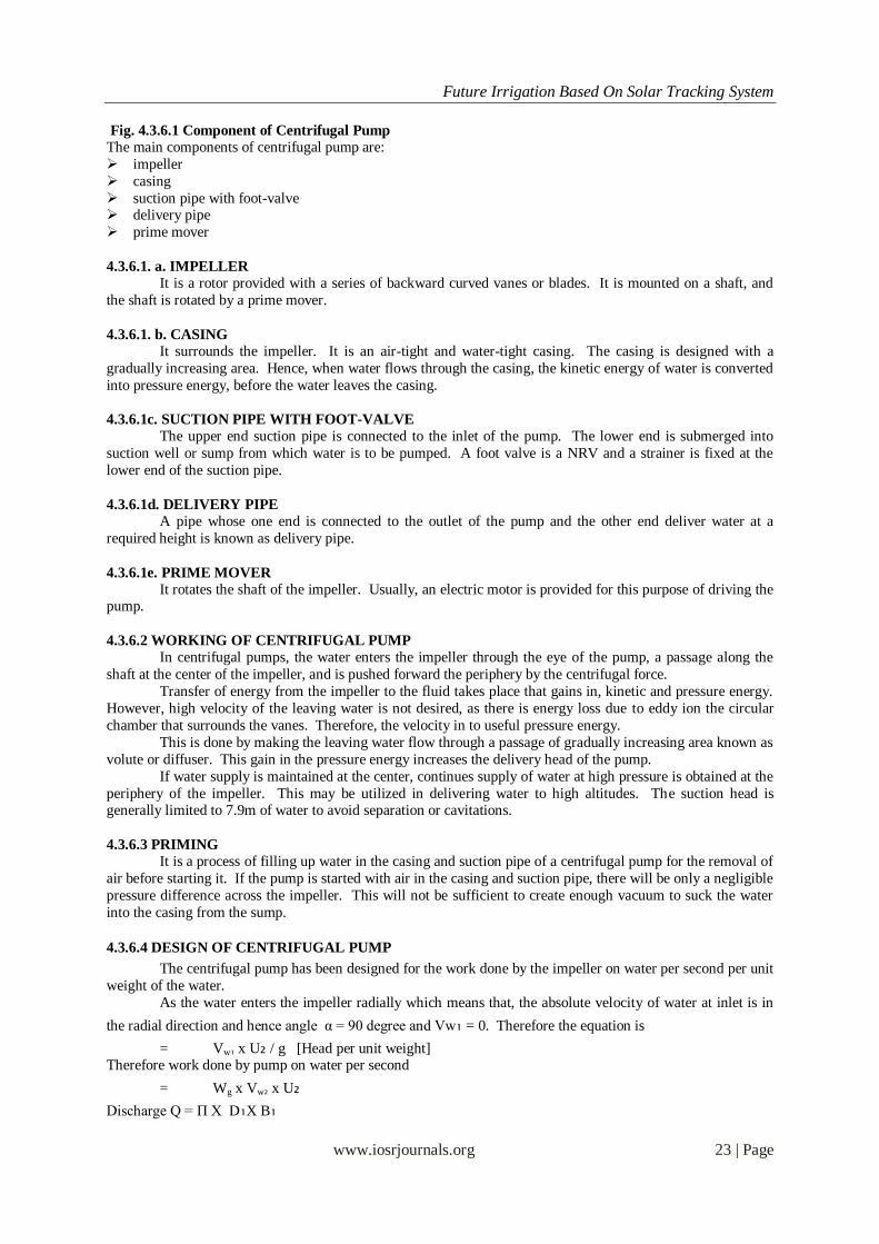
Fig. 4.3.6.1 Component of Centrifugal Pump
The main components of centrifugal pump are:
impeller
casing
suction pipe with foot-valve delivery pipe
prime mover
4.3.6.1. a. IMPELLER It is a rotor provided with a series of backward curved vanes or blades. It is mounted on a shaft, and
the shaft is rotated by a prime mover.
4.3.6.1. b. CASING
It surrounds the impeller. It is an air-tight and water-tight casing. The casing is designed with a
gradually increasing area. Hence, when water flows through the casing, the kinetic energy of water is converted
into pressure energy, before the water leaves the casing.
4.3.6.1c. SUCTION PIPE WITH FOOT-VALVE
The upper end suction pipe is connected to the inlet of the pump. The lower end is submerged into
suction well or sump from which water is to be pumped. A foot valve is a NRV and a strainer is fixed at the
lower end of the suction pipe.
4.3.6.1d. DELIVERY PIPE
A pipe whose one end is connected to the outlet of the pump and the other end deliver water at a
required height is known as delivery pipe.
4.3.6.1e. PRIME MOVER
It rotates the shaft of the impeller. Usually, an electric motor is provided for this purpose of driving the pump.
4.3.6.2 WORKING OF CENTRIFUGAL PUMP
In centrifugal pumps, the water enters the impeller through the eye of the pump, a passage along the
shaft at the center of the impeller, and is pushed forward the periphery by the centrifugal force.
Transfer of energy from the impeller to the fluid takes place that gains in, kinetic and pressure energy.
However, high velocity of the leaving water is not desired, as there is energy loss due to eddy ion the circular
chamber that surrounds the vanes. Therefore, the velocity in to useful pressure energy.
This is done by making the leaving water flow through a passage of gradually increasing area known as
volute or diffuser. This gain in the pressure energy increases the delivery head of the pump.
If water supply is maintained at the center, continues supply of water at high pressure is obtained at the
periphery of the impeller. This may be utilized in delivering water to high altitudes. The suction head is generally limited to 7.9m of water to avoid separation or cavitations.
4.3.6.3 PRIMING
It is a process of filling up water in the casing and suction pipe of a centrifugal pump for the removal of
air before starting it. If the pump is started with air in the casing and suction pipe, there will be only a negligible
pressure difference across the impeller. This will not be sufficient to create enough vacuum to suck the water
into the casing from the sump.
4.3.6.4 DESIGN OF CENTRIFUGAL PUMP
The centrifugal pump has been designed for the work done by the impeller on water per second per unit
weight of the water.
As the water enters the impeller radially which means that, the absolute velocity of water at inlet is in
the radial direction and hence angle α = 90 degree and Vw₁ = 0. Therefore the equation is
= Vw₁ x U₂ / g [Head per unit weight] Therefore work done by pump on water per second
= Wg x Vw₂ x U₂
Discharge Q = Π X D₁X B₁

Future Irrigation Based On Solar Tracking System
www.iosrjournals.org 24 | Page
HEAD OF THE PUMP:
The head of a centrifugal pump may be expressed in two ways,
static head
mono metric head
static head is the net total vertical lift through which water is lifted by the pump. Manometric head is defined as the head against which a centrifugal pump has to work.
Hm = Work done per kg of water – impeller losses
= (Vw₂ * U₂ / g) – impeller losses Hm = hs + hfs + hd + hfd + (Vd²/2g)
4.3.6.5 EFFICIENCIES OF A CENTRIFUGAL PUMP
The efficiency of a centrifugal pump may be expressed in the following forms,
Manometric efficiency Mechanical efficiency
Over all efficiency
Manometric efficiency or hydraulic efficiency
η mano or η hyd = manometric head / energy supplied
by the Impeller/Kg of water
=Hm / ( Vw₂ x u₂ / g )
=g x Hm / ( Vw₂ x u₂ ) η mech =Energy available at the impeller / energy suppliedto the pump by the prime mover.
η overall =Actual work done by the pump / Energy supplied to the pump by the prime mover.
=(ρ x g x Q x Hm) /
=η mech x η hyd
V. CHAPTER
COMPARISION AND EVALUATION RESULTS
5.1 OUTPUT GRAPH
7…8…1…1…1…1…1…0
20
Vo
ltag
e (
V)
Voltage - Time
Graph 5.1 Time Vs Voltage Graph
The graph is recorded between voltage and time on a day to analyze the performance of the solar
tracking array with respect to a fixed array.
It is analyzed that the utilization of solar energy is better by the solar tracking system than that of the
fixed array. The output voltage is increased by 33.46 % than that of the fixed plate. The above readings are
taken at various intervals of time on a hot sunny day. The readings give a very good data analysis of the energy production by utilizing solar energy.
Rate of Flow = 3 L / min
Duration = 10 Hours
5.2 COMPARISON OF RESULT
The average voltage output by a PV tracking array for a day is 10.12 V. The average voltage output for
a fixed array of same rating is 6.97 V. The voltage output is increased by 31.12 % than that of fixed array.

Future Irrigation Based On Solar Tracking System
www.iosrjournals.org 25 | Page
VI. CHAPTER CONCLUSION
6.1 OVERALL CONCLUSION
This project is one time installation cost and is having very low maintenance cost. As this project is simple in construction and can be easily implemented in rural side .It is not dependent on Non Renewable
energy sources and also eco friendly.
Not only that it will reduce the farming cost which will ultimately beneficial to the common people as
well as the government in controlling the inflation on the food products and will also save non renewable energy
like coal and petroleum of our country.
6.2 FUTURE SCOPE OF THE PROJECT
We are using DC Motor coupled to the centrifugal pump for pumping water runned by the battery
which is charged by solar or wind energy. Now the maintenance cost of the DC motor is very low because of
non use of brush and commutator. The input voltage increases according to the increase in the H.P of the motor.
Its input voltage ranges from12v to 300v dc and has very high rpm up to 30000 rpm. This input can easily be achieved by solar and wind power.
This is one of the simple and eco friendly project the installation of the solar and wind power cost one
time installation and free power for ever with very less maintenance. Consideration of the government on the
installation of the solar panel and wind mills can bring electricity to each and every village and rural areas
which they can use in irrigation of their farm land, pumping drinking water from the well and underground
borings.
VII. CHAPTER
References
1. Grug SK. 1989. Irrigation engineering and hydraulic structures. 8th ed. Khama Publishers, New Delhi, India. 1291 pp.
2. Kay M and Brabben T. 2010. Treadle pumps for irrigation in Africa. Knowledge Synthesis Report No. 1. IPTRID Secretariat. FAO
(Food and Agriculture Organization of the United Nations), Rome, Italy.
3. Mangisoni J. 2006. Impact of treadle pump irrigation technology on smallholder poverty and food security in Malawi: A case
study of Blantyre and Mchinji Districts. Report written for IWMI. IWMI (International Water Management Institute), Pretoria, South
Africa.
4. Michael AM. 1990. Irrigation: Theory and practice. Vikas Publishing House, New Delhi, India. 801 pp.
5. Mloza-Banda H. 2011. Experiences with micro irrigation technologies and practices: Malawi. Report written for
6. IWMI. IWMI (International Water Management Institute), Pretoria, South Africa.
7. Shah T, Alam M, Dinesh Kumar M, Nagar RK and Singh M. 2000. Pedaling out of poverty: Socio-economic impact of a manual irrigation
technology in South Asia. Research Report 45. IWMI (International Water Management Institute), Colombo, Sri Lanka.
8. Shah T, van Koppen B, Merrey D, de Lange M and Samad M. 2002. Institutional alternatives in African smallholder irrigation: Lessons
from international experience with irrigation management transfer. IWMI Research Report No. 60. IWMI (International Water
Management Institute), Colombo, Sri Lanka.
9. Shigemichi I and Shinohara K. 2004. The impact of treadle pump on small-scale farmers in Malawi. Total Land
10. Care. New Building Society House, Lilongwe, Malawi.