fusion energy advisory committee
TRANSCRIPT

DOE/ER-0571T
FUSION ENERGY ADVISORY COMMITTEE
Advice and Recommendationsto the Department of Energy
In Partial Response to the Charge Letterof September 24, 1991: Part E
November 1992
U.S. Department of EnergyOffice of Energy ResearchWashington, DC 20585

FUSION ENERGY ADVISORY COMMITTEEAdvice And Recommendations ToThe U.S. Department Of Energy.
In Partial Response To The Charge LetterOf September 24, 1991: Part E
Members of FEAC
Robert W. Conn, ChairmanDavid E. BaldwinKlaus H. BerknerFloyd L. CullerRonald C. DavidsonStephen O. DeanDaniel A. DreyfusJohn P. HoldrenRobert L. McCrory, Jr.Norman F. NessDavid 0. OverskeiRonald R. ParkerRichard E. SiemonBarrett H. RipinMarshall N. RosenbluthJohn SheffieldPeter StaudhammerHarold Weitzner
FEAC/92-IV November 6, 1992
3
Table of Contents
Preface Page 5
The initial letter of charge to FEAC from Page 6Dr. William Happer, dated September 24, 1991.
First supplementary letter of charge to FEAC from Page 8Dr. William Happer, dated February 20, 1992.
Second supplementary letter of charge to FEAC Page 10from Dr. William Happer, dated Jume 22, 1992.
The letter of charge to Panel #4 from Dr. Robert Page 11W. Conn, dated June 8, 1992, that arose as aresult of the May 19-21, 1992 meeting.
FEAC's letter that accompanied the transmission Page 13of the report of Panel #4 to Dr. William Happer,dated November 6, 1992.
Appendix I Page 15
The report to FEAC of Panel #4,dated September 22, 1992.
Appendix II
Minutes of FEAC Meeting ofSeptember 22423, 1992.
4
Preface
This document is a compilation of the written records that relate tothe Fusion Energy Advisory Committee's deliberations with regard tothe Letters of Charge received from the Director of Energy Research,dated September 24, 1991, February 20, 1992 and June 22, 1992.
During its fifth meeting, held in September 1992, FEAC provided adetailed response to the charge contained in the letter of June 22,1992. In particular, it responded to the sentence:
"I am asking for your best technical judgement on how tostructure the magnetic fusion program within thesedifferent funding assumptions, but without change in thebasic goal of demonstrating fusion power and within thebasic assumption of strong international collaboration."
The response was prepared in the form of a report entitled "FusionEnergy Advisory Committee Report on Program Strategy for U.S.Magnetic Fusion Energy Research", dated September 23, 1992. It hasbeen published by the U.S. Department of Energy as a separatedocument.
To assist with their response to the charge, FEAC established aworking group, designated Panel #4, which reviewed priorities in theU.S. intermediate confinement experiments in detail. This panelprepared background material which was provided to FEAC during itsSeptember 1992 meeting to help with its deliberations. The report ofPanel #4 is included in this report as Appendix I.
5

SEPTEMBER 24, 1991
CHARGE TO FUSION ENERGY ADVISORY COMMITTEE
Introduction
A year ago, the Fusion Policy Advisory Committee (FPAC) reported its findingsand recommendations on fusion energy programs of the Department of Energy(DOE). The Secretary of Energy adopted FPAC's recommendations subject toexisting budget constraints. This translated to terminating work onalternative confinement concepts and pursuing only the tokamak concept withinthe magnetic fusion energy program, as a precursor to a Burning PlasmaExperiment (BPX) that would be integrated into a larger international fusionenergy program. Fusion energy was highlighted in the National EnergyStrategy, which mentioned both the International Thermonuclear ExperimentalReactor (ITER) and BPX as major elements of the program. The Secretarytravelled to Europe earlier this year to conduct personal discussions with theItalian government on their potential interest in a bilateral agreement onBPX.
Since that time, a number of events have led to a reexamination of thestrategy being used to pursue an energy-oriented fusion program. Theestimated cost of BPX has increased and foreign interest in substantialparticipation has not materialized. Last week, the Secretary of EnergyAdvisory Board Task Force on Energy Research Priorities was asked to reviewthe relative priority of the BPX proposal among the programs of the Office ofEnergy Research and to recommend on the appropriate tasking to the FusionEnergy Advisory Committee (FEAC). The Task Force recommended that the DOE notproceed with BPX, but rather focus on ITER as the key next step after theTokamak Fusion Test Reactor (TFTR) and the Joint European Torus in developingthe physics of burning plasmas, along the lines currently being proposed bythe European Community. The Task Force also recommended that the U.S. fusionenergy program continue to grow modestly (even in an ER budget that isdeclining in constant dollars) and suggested that a more diverse program thatincluded a less costly follow-on device to TFTR in the U.S. would be moreeffective in the long run.
Charge
I would like to explore seriously the programmatic implications of thisrecommendation under two budget scenarios -- a constant dollar budget formagnetic fusion through FY 1996 and a budget at 5 percent real growth per yearthrough FY 1996. 1 am therefore charging the FEAC to advise me on thefollowing questions.
1. Identify how available funds now used for BPX, as well as a modestincrease (described above) could be used to strengthen the existing baseprogram for magnetic fusion research.
2. Within the above envelope of funding, identify what follow-onexperimental devices for the U.S. fusion program might be planned foruse after the completion of experiments at TFTR and before the plannedstart of ITER operation. For such devices, indicate how they would fitinto the international fusion program.
6
3. What should be the U.S. position on the appropriate scope, timing, andmission of ITER if BPX does not go forward?
Although you will need some months to complete the work envisioned in thischarge, I would like to have your initial thoughts on the above three topicsin a letter report from your meeting of September 24-25, 1991.
Then, by January 1992, I would like to have your recommendations on theappropriate scope and mission of ITER and any suggestions you can make tolower its cost or accelerate its schedule. At the same time, I would likeyour recommendations on the relative importance to the U.S. of the variousITER technology tasks, on the role and level of U.S. industrial involvement inthe ITER engineering design activity, and on the balance between ITER project-specific R&D and the base program.
By March 1992, I would like your views on how to fill the gap in the U.S.magnetic fusion program between the completion of TFTR work and the plannedstart of ITER operation. In addressing this issue, please includeconsideration of international collaboration, both here and abroad.
By May 1992, I would like to have your recommendations on a U.S. conceptimprovement program, including relative priorities and taking into accountongoing and planned work abroad.
William HapperDirectorOffice of Energy Research
7

Department of EnergyWashington. DC 20585
February 20, 1992
Dr. Robert W. ConnChairman, Fusion Energy
Advisory CommitteeUniversity of California, Los Angeles6291 Boelter HallMechanical, Aerospace, and Nuclear
Engineering DepartmentLos Angeles, CA 90024-1597
Dear Dr. Conn:
I am writing to expand on the portion of the charge you received September 24,1991, regarding concept improvement. Specifically, that charge asked "By May1992, I would like to have your recommendations on a U.S. concept improvementprogram, including relative priorities and taking into account ongoing andplanned work abroad." I understand that you discussed this charge element atyour meeting on February 6 in California, forming a panel (#3) to developinformation and requesting some points of clarification from DOE. I furtherunderstand that possible major program elements which address tokamakimprovement, such as TPX and the ATF/PBX-M facilities, are already well alongin your review process through Panel 2.
Given that tokamak reactor development will be the primary focus of the U.S.magnetic fusion program, it is reasonable to ask what activities areappropriate on non-tokamak concepts and on small-scale exploration of tokamakimprovements. There are a number of ideas on alternate concepts and tokamakimprovements, and the exploration of these ideas has historically addedrichness and innovation to magnetic-fusion development. It would be useful ifyou could recommend a policy and selection criteria to help guide our programchoices on concept improvements within our goal-oriented program strategy.The overall policy question is whether, given the demands of the mainlinetokamak program and current budget constraints, we should encourage and fundproposals on concepts other than tokamaks.
Within the concept improvements area, what priorities should be given toexploratory tokamak improvement proposals, like the compact toroid fueling andhelicity current drive that are now under small scale investigation? Shouldthe priority be higher for U.S. alternate concept activities that connect tomajor significant international programs or for unique U.S. activities? Underwhat conditions and within what criteria should concepts that have littleconnection to tokamaks, or to other major international programs, beconsidered?
8

I know that these issues are of intense interest to some members of the U.S.fusion community. It is important to have your best judgment on thesequestions within the context of overall magnetic fusion program goals,strategies, and funding constraints.
Sincerely,
William HapperDirectorOffice of Energy Research
9

Department of EnergyWashington. DC 20585
June 22, 1992
Dr. Robert W. ConnChairman, Fusion Energy
Advisory CommitteeUniversity of California, Los AngelesLos Angeles, CA 90024-1597
Dear Bob:
The Fusion Energy Advisory Committee (FEAC) has now reviewed and reported onthe primary elements of the magnetic fusion program. Given that background,it would be quite helpful if FEAC would provide recommendations on strategicprogram planning. Please provide your views for three different out-yearfunding assumptions: starting with the FY 1993 House Appropriation Mark ofS331M for magnetic fusion, (A) 5 percent real growth; (B) level funding, i.e.,with only inflation; (C) flat, without inflation. Of course, the FY 1993budget process is still incomplete, and I will revise this guidance if we havebetter figures before you meet.
Within these assumed cases, which program elements should be enhanced,protected, reduced, or eliminated and on what schedule? In all cases theprimary goal should be maximum progress toward a Demonstration Power Plant. Iam asking for your best technical judgment on how to structure the magneticfusion program within these different funding assumptions, but without changein the basic goal of demonstrating fusion power and within the basicassumption of strong international collaboration.
Please provide your recommendations by the end of September 1992. I know thatall FEAC members have worked intensely to develop your recommendations on theindividual program elements in my first set of charges. Therefore, I believeit is most useful to take this overview now while the contextual informationis fresh. I realize that this will require additional dedication on top ofyour already extensive labors. I do appreciate your efforts.
Sincerely,
William HapperDirectorOffice of Energy Research
10

UNIVERSITY OF CALIFORNIA, LOS ANGELES UCLA
BERKELEY * DAVIS * IRVINE * LOS ANGELES * RIVERSIDE * SAN DIEGO * SAN FRANCISCO SANTA BARBARA * SANTA CRUZ
INSTITUTE OF PLASMA AND FUSION RESEARCH44-139 ENGINEERING IV
405 HILGARD AVENUELOS ANGELES, CALIFORNIA 90024-1597
(213) 825-4544FAX (213) 825-2599
Dr. David Baldwin, LLNL June 8, 1992Dr. Harold Weitzner, NYU
Dear David and Harold:
Thank you for agreeing to be chair and vice-chair of FEAC Panel 4 on "Priorities inthe Intermediate Confinement Experiments." Your report will provide important input tothe FEAC workshop in July on priorities in the overall fusion program. In addition, it willassist the FEAC in reaching its specific recommendation in September on the operation ofATF.
The facilities in the toroidal program that you are asked to evaluate and prioritize arethe ATF stellarator and the PBX, and C-Mod tokamaks. This should be done against thebackground of the DIII-D and TFTR capabilities, assuming that full D-T operation in TFTRbeginning in mid-1993 and a strong DIII-D program are supported as recommended in theApril 1 FEAC letter to Dr. Happer. As described below, I ask you to focus more on afactual evaluation for our July meeting, leaving for September a more completedetermination of a basis for FEAC recommendations on priorities.
For the July meeting, please provide the following information for each of theidentified mid-scale toroidal facilities:
1. The physics issues that are addressable in this class of facility and thecompleteness wiB wWch each of the identified devices can address these issues:and
2. For each device, the goals and objectives, additional hardware, the strengths,uniqueness, limitations, present status, projected costs and time required toachieve its objectives.
In addition, for the July meeting, please provide preliminary priorities and their time scalethat your Panel would assign to the operation of these facilities, along with an indication ofthe reasoning behind these priorities.
At the July meeting, the full FEAC will make use of your evaluations and your draftpriorities in its examination of the broader program. Later, in time for the Septembermeeting, I would like your panel to reexamine its preliminary priorities in light of theFEAC's July workshop and feedback provided there. Further, this will provide anopportunity for your Panel to hear responses from the programs reviewed. Your revisedpriorities will then serve as input to the September meeting of FEAC. This two-stepprocess will provide ample opportunity for each program to have a fair opportunity toanswer questions and concerns.
11

When this process has been completed, the FEAC must answer the followingquestions:
1. If the fusion budget is sufficient to do so, do all of the facilities warrantoperation? If not, which ones do not warrant operation?
2. If the fusion budget is not sufficient to operate simultaneously all thefacilities which warrant operation,
a) Should their operation be phased, implying one or more machines would bemothballed, and if so how?
b) Should all be operated at a reduced level? orc) Should one or more be closed down, and if so in what priority order?
The combination of your evaluations and priorities should be sufficient to permitFEAC to respond to Dr. Happer's request concerning the ATF and other priorities. Iunderstand that this will not be an easy undertaking for your Panel, for FEAC, or for theprograms involved since all are staffed by high quality groups. I will do all that I can toassist you in this endeavor.
Sincerely,
Robert W. Conn
12

UNIVERSITY OF CALIFORNIA, LOS ANGELES UCLA
BERKELEY * DAVIS * IRVINE * LOS ANGELES * RIVERSIDE * SAN DIECO * SAN FRANCISCO SANTA BARBARA · SANTA CRUZ
ROBERT W. CONN OFFICE OF THE DIRECTORDIRECTOR AND PROFESSOR INSTITUTE OF PLASMA AND FUSION RESEARCH
44-139 ENGINEERING IV405 HILGARD AVENUE
November 6, 1992 LOS ANGELES. CALIFORNIA 90024-1597(213) 825-4544
FAX: (213) 206-4832
Dr. William HapperDirectorOffice of Energy ResearchU.S. Department of EnergyWashington, D.C. 20585
Dear Dr. Happer,
Recently, I forwarded to you the report of the Fusion EnergyAdvisory Committee relating to strategic planning for futureactivities in magnetic fusion energy research. As part of the processthat led up to that report, FEAC established a panel that reviewedpriorities in the intermediate confinement experiments and thatprovided background to FEAC during its deliberations. Thebackground material was presented to FEAC both verbally and in theform of a written report. I am forwarding with this letter a copy ofthat panel report.
Sincerely,
Robert W. ConnRobert W. ConnChairmanon behalf of theFusion Energy Advisory Committee
13

~~~~~t14 *
1 4

Appendix I
The report to FEAC of Panel #4,dated September 22, 1992.
15
Report from Panel 4 of the
Fusion Energy Advisory Committee
on
Priorities in the Intermediate Confinement Experiments
David Baldwin (Chair)*Lawrence Livermore National Laboratory
Harold Weitzner (Vice Chair)*New York University
Steve Dean*Fusion Power Associates
Richard D. HazeltineUniversity of Texas, Austin
Neville C. LuhmannUniversity of California, Los Angeles
Stewart PragerUniversity of Wisconsin
Barrett H. Ripin*Naval Research Laboratory
Marshall N. Rosenbluth*University of California, San Diego
Richard E. Siemon*Los Alamos National Laboratory
Alan WoottonUniversity of Texas, Austin
September 22, 1992
* Member of FEAC
This report was prepared by a panel established by, and reporting to, the Fusion EnergyAdvisory Committee (FEAC). The report of this panel should not be construed asrepresenting the views, official advice or recommendations of FEAC.
INTRODUCTION AND BACKGROUND
In a letter dated June 22, 1992, Dr. Will Happer, Director, Office of Energy Research,
requested that the FEAC address the priorities within the MFE program under several
budget scenarios. As part of the preparation for answering this charge, Panel 4 was
created by the FEAC chairman, Professor Robert Conn, whose charge letter to the Panel
is contained in the Appendix. He asked the Panel to assemble background information on
three mid-sized toroidal facilities, the Alcator C-Mod and PBX-M tokamaks at the
Massachusetts Institute Technology and the Princeton Plasma Physics Laboratory,
respectively, and the ATF stellarator at the Oak Ridge National Laboratory and to
provide draft conclusions to the FEAC on the question of priorities. The Panel was later
asked to provide similar background information on the proposed DIII-D Upgrade, in
view of the fact that the Upgrade objectives encompassed many of those of the three
smaller facilities.
The following four sections contain summaries of the four machines' capabilities and
their places in the world programs. These summaries were prepared with the cooperation
of the respective research groups. Draft positions of the Panel on priorities were
communicated directly to FEAC as part of its deliberations, the conclusions of which
will be available at the September 1992 FEAC meeting. Because the priority
recommendations of the FEAC supersede those of Panel 4, the issue of priorities have not
been revisited by the Panel, as had originally been planned.
ALCATOR C-MOD
A. Program Plan
The purpose of the Alcator C-Mod program is to address a range of critical issues
confronting the development of the tokamak as a viable fusion reactor concept. These
issues include power and particle handling, control, enhanced transport, and RF heating
and current drive. The high magnetic field (9T) and strong shaping (K = 1.8) of Alcator
C-Mod result in plasma currents up to 3 MA, projecting to plasma performance
comparable to the best so far achieved in any tokamak. The state of the art plasma
diagnostic complement and ample port access combine with the unique characteristics
associated with the high particle-, power, and current- densities of this relatively small
size device to position Alcator C-Mod as a premier research facility in the world tokamak
program.
Alcator C-Mod has a unique capability to address the problem of power handling in an
ITER- (and reactor-) relevant divertor geometry. The surface power density (total power
divided by plasma surface) in C-Mod is in the range of 0.5-1 MW/m2 , which exceeds the
level required in ITER and is typical of a reactor. A major objective of the Alcator
research program is to demonstrate a solution to the problem of divertor power handling
at reactor-relevant power densities, in a manner consistent with clean, high performance
core plasmas. Our initial approach focuses on reactor-relevant metaiiic plasma facing
components, an inclined-plate, semi-closed divertor geometry, and the high-recycling,
radiative modes of divertor operation.
Alcator C-Mod also offers unique opportunities for addressing problems of axisymmetric
stability, disruption avoidance and control, as well as for characterizing disruption effects.
The low vacuum vessel resistance and the conducting super-structure are particularly
relevant to ITER, as is the magnetic configuration. Extensive diagnostics are installed to
monitor heat deposition, halo currents (including toroidal variation), and power balance.
The hybrid analog/digital control system can be used both for disruption avoidance and to
implement optimized ramp-down techniques to minimize electromagnetic loads.
The physics and scaling of confinement remain vital topics determining the feasibility
and attractiveness of a fusion reactor. Two general issues must be addressed: transport
prediction and confinement improvement. The Alcator C-Mod program aims to advance
-2-

this area of fusion research both through fundamental studies of transport and by
investigation and development of enhanced confinement modes. The unique parameter
range accessible on Alcator C-Mod (high field, high density, small size) can be used to
test dimensionless similarity scaling by comparison with larger, low-field devices, such
as DIII-D and ASDEX-U, which operate with the same non-dimensional parameters. C-
Mod will extend the study of enhanced confinement to unique densities and magnetic
fields, of direct applicability to future devices of the IGNITOR class or reactors in the
ARIES line. It will also establish the scaling of confinement and access to enhanced
confinement regimes. Of particular interest is the possibility of enhancing confinement atreduced current (high q*, high 3 leading to an attractive reactor scenario with substantial
bootstrap current and modest RF current drive requirements, as exemplified by the
ARIES I study.
In addition to providing bulk heating power for the divertor and confinement studies, the
ICRF program on Alcator C-Mod aims to optimize antenna performance at high RFpower densities (>10 MW/m2 ) and to determine the heating effectiveness of various
ICRF heating scenarios. These studies should lead to optimized antenna design for ITER
and reactor type devices. ICRF will also provide heating power for long pulse, lower-
hybrid current driven plasmas as part of the advanced tokamak studies program. The
goal of these experiments will be to demonstrate noninductive current drive operation,
including profile control, in combination with substantial bootstrap current, for time
durations in excess of the L/R time, and to study the confinement in such discharges at
reactor-like densities, magnetic fields, and q* values. These experiments will also
address the compatibility of such non-inductively driven operation with high
performance, low Zeff core plasmas and high heat flux divertor operation.
The culmination of the C-Mod program would thus be a demonstration of the
combination of essential features of an attractive tokamak reactor, namely high
confinement, non-inductively sustained current, low impurity content, and reactor-
relevant divertor power density.
B. Divertor and Edge PhysicsB.1 Introduction
Alcator C-Mod is designed with a closed divertor (see figure 1.2). This design is
complemented by the very wide range in densities that can be achieved with a high
magnetic field. The combination of these geometrical and plasma characteristics creates
-3-

an ideal environment in which to test the radiative and gaseous divertor concepts.
Additional unique aspects of the Alcator C-Mod divertor are the high-Z divertor material,
metal walls and a highly-inclined plate (poloidal angle - 15°, toroidal angle - 1°). It is
an important contribution to divertor designs to test the compatibility of such features
with ITER-level power- and particle-densities. Since the upper divertor has an open, flat-
plate geometry, it will be possible to perform direct comparisons of closed and open
divertor performance on a single tokamak. C-Mod has an extensive array of edge and
divertor diagnostics which will be used to characterize the edge transport of plasma and
impurities, and their divertor plate interactions.
A unique contribution of the Alcator C-Mod divertor program lies in our ability to
provide results with plasma parameters, divertor geometry and divertor material which
are significantly different from those being investigated elsewhere in the world program.
Essentially all divertor tokamaks, other than C-Mod, operate with essentially similar
plasma parameters (ne, Te, B). To make matters worse, the bulk of data from these
experiments are at electron densities, power densities and magnetic fields which are
significantly lower than those envisaged for ITER or ARIES. The consequence is that
present modeling is based on a narrow set of data with geometries unlike those being
considered for next step devices. With the data from Alcator C-Mod, it will be possible
to make interpolations in a number of areas, rather than extrapolations, to ITER and
ARIES.
B.2 Divertor Integrity
Control of the power deposited on the divertor plates, during normal operation as well as
disruptions, is a central limiting factor in the present ITER design. For example, the
predicted peak heat loads for the ITER CDA are 10-30 MW/m 2 , levels which are beyond
the steady-state heat removal capabilities of present technology in anything other than
small laboratory experiments. However, included in the heat load specification is an
uncertainty of a factor - 5 which is composed of an amalgam of uncertainties associated
with such variables as scrapeoff lengths, inner-outer divertor asymmetrical loading (from
plate to plate) and toroidal peaking factors. The uncertainties are due to the sparsity of
data and the dissimilarity of the geometries of presently operating tokamaks compared to
ITER. It is clear that no matter how the predictions of the divertor plate heat loads for
ITER might be reduced, either through advanced divertor physics (e.g., radiation) or by
reduction of uncertainties, any such decreases could have an enormous impact on the
overall ITER design.
-4-

Alcator C-Mod will have maximum surface power density (total power divided by
plasma surface area) in the range 0.5-1 MW/m 2, and divertor plate power densities in the
range 5-30 MW/m2 . These values make the power handling problems prototypical of
ITER and tokamak reactors.
An extensive array of edge diagnostics will provide information on the heat loads and the
uncertainties associated with their prediction. These include 220 thermocouples
measuring first-wall tile temperature distributions, a poloidal array of IR tile surface
temperature measurements, a poloidal array of 48 Langmuir probes inset flush in the
closed divertor surfaces, and a pneumatically-driven Langmuir probe in the SOL.
Langmuir probes have also been placed in the outboard limiter and the ICRF antenna
protection tiles. Comparisons of measured heat loads with those predicted from
measured plasma parameters at the plate will provide important tests of the standard
sheath transmission model at small field-line angles of incidence. Edge modeling is
crucially dependent on the heat transmission factor boundary conditions and on a
knowledge of particle and heat diffusivities in the SOL. The density and temperature e-
folding lengths measured by the probes, and other diagnostics such as reflectometry and
spectroscopy, will provide a measure of the diffusivities and insights into the underlying
transport processes.
Disruptions also affect divertor integrity. In addition to the subs.:ntial heat loads
generated during disruptions, another important disruption effect is the generation of halo
currents flowing poloidally through the first-wall and vacuum vessel. These currentsinteract with the toroidal field, producing forces which have caused damage to the tiles
and other in-vessel structures in some tokamaks. The details of these currents are not
well understood. The outer closed divertor plates of Alcator C-Mod are designed so that
they can be electrically isolated from the vacuum vessel; at present they are connected to
the vessel through current shunts. The current flowing through each of the 10 toroidal
divertor segments will be measured to determine the magnitude, time duration and
toroidal variation of disruption-induced halo currents, and thus to infer the resultant
forces. The divertor probe array will yield information about the poloidal profile of halo
currents at the divertor surface, as well as about the local plasma evolution during
disruptions.
-5-

B.3 Divertor Lifetime
The plasma-induced erosion rate of plate material is of great concern in determining first
wall longevity. For ITER and ARIES, the erosion rate due to evaporation and sputtering
is predicted to be large. However, the redeposition rate of the eroded material is
predicted to compensate much of this, so that the net erosion rate is much smaller. The
operational data base relevant to this question is small, particularly with respect to the
effect of highly inclined divertor plates (poloidal angle - 15°) found in ITER CDA,
ARIES and Alcator C-Mod. It is unknown whether the movement of material swept
along a plate due to erosion/redeposition cycles will be an important factor or not.
Perhaps of greater import is the erosion which occurs during disruptions. Predictions for
net erosion in ITER with carbon tiles imply that disruptions will lead to the need to
replace the divertor anywhere from 1 to 17 times during the physics phase. The
uncertainty of this prediction is due primarily to the unknown protection characteristics of
the plasma vapor shield, and to the unknown toroidal and poloidal heat load distributions.
There are similar uncertainties for tungsten as the divertor material.
The Alcator C-Mod staff is currently working with Sandia National Laboratory,
Livermore (SNL-L) to characterize our molybdenum tile surfaces. After each period of
operation, beta-backscattering will be used to monitor, in-situ, changes in the surface.
Periodically, sample tiles at different poloidal locations will be removed for more in-
depth analysis. In-situ measurement of the erosion rate (not net erosion) will be made
utilizing 1 and 2-D spectroscopic imaging of the divertor surfaces at wavelengths
corresponding to neutral molybdenum emission. The time integrals of these data can be
compared with the net erosion/redeposition rate, and the redeposition inferred. The
measured Mo source rates will also be compared to those calculated from knowledge of
the hydrogen fluxes, sheath potential and sputtering rates, thus providing information on
the effect of small field line incidence angles on sputtering rates. The above diagnostics
can also be used to characterize disruption erosion and the resulting metal plasma vapor
shield.
B.4 Particle Control
There are two stages at which the inflow of impurities can be controlled: (1) source
reduction of impurities and (2) reduction of their transmission to the central plasma. The
impurity source rate at the divertor plate can be reduced by lowering sputtering (lower Te
and Ti) or by reduction of evaporation (heat loads). The effect of the small field line
-6-

incidence angle on sputtering rates and ion sheath acceleration could be beneficial, but atpresent this is quite uncertain. The wall impurity source can likewise be reduced throughreduction of the high-energy charge-exchange neutral flux from the central plasma(operation at high density) and through (better bonding of 02 to wall; covering ofmetals). Once an impurity is generated, the second level of protection becomesimportant, namely impurity screening by reduction in neutral impurity transmissionthrough the edge plasma and flow of the corresponding impurity ions into the divertor.The processes involved in SOL plasma flows are poorly understood, and there is littleexperimental data concerning flow patterns.
A number of periscope systems are being installed on C-Mod to provide spectroscopicviews (1- and 2-D) of the walls, divertor plates and antennas. The source rates forimpurities at these locations will be measured as functions of changing central anddivertor plasma conditions. The impurity screening efficiency can be calculated througha model which uses measured divertor and SOL plasma parameters and known ionizationand charge-exchange processes. This model will be compared to measurements ofimpurity densities in the central plasma (VUV and X-ray emission) and in the SOL(Omegatron mass-spectrum analyzer).
Flows in the SOL are a vital factor in determining the impurity screening efficiency. Itappears that flow reversal, with resulting stagnation points, must exist, but this is notexperimentally confirmed. It is important to understand these flows .:J, specifically, tocompare different plasma geometries (open vs. closed divertor) under the same plasmaconditions. JET and DIII-D have operated with open, flat-plate divertors that have beenutilized for obtaining H-mode, not particle control, but the ITER CDA and ARIESdivertor geometries are of a more closed nature.
The Alcator C-Mod divertor program emphasizes the diagnostic characterization of SOLflows. A Mach probe will be the initial flow diagnostic for the SOL. In addition, amultiple-point gas puffing system will be used to inject trace impurities at differentpoloidal locations and the flow of those impurities followed by their emission. Directspectroscopic measurements of doppler shifts will also be made.
The plasma parameters in the divertor and the divertor geometry have important roles inimpurity retention. It seems likely that the higher the density in the divertor (opaque toneutrals) and the more closed the divertor geometry (mechanical baffle), the better its
-7-

impurity retention properties. High divertor densities can also improve hydrogenic
neutral exhaust (proportional to the divertor neutral pressure) with a concomitant
improvement of density control in the central plasma. However, the neutral pressure in
the divertor cannot be increased indefinitely; the neutrals can blow-through back to the
main plasma and have effects on the density and confinement there.
The closed and open divertor geometries, combined with the high densities found in
Alcator C-Mod, provide a unique ability to explore the allowable limits of neutral
pressure (and pumping). Initial experiments will focus on the use of 3 gas gages to
measure the divertor and general vessel pressures. The divertor neutral pressure can be
varied utilizing some of the 28 capillary gas puffing tubes inset in the tiles. This will
determine the limits of neutral pressure for a given set of divertor and plasma conditions.
The effects on the divertor plasma characteristics will be monitored as well.
For helium exhaust, high pressure in the divertor is not enough. Methods have been
proposed to pump helium preferentially, including semi-permeable membranes, material
surfaces that pump helium preferentially (helium self-pumping) and optimized pump duct
geometries. All of these methods need to be tested for high particle and heat flux
conditions, with both high-Z and carbon first-wall tokamaks.
Alcator C-Mod and SNL-L are determining the applicability of using the helium self-
pumping technique (developed by SNL-A/ANL and used on TEXTOR) to C-Mod. For
Alcator C-Mod, nickel wo!d again be a suitable material. However, other materials,
including molybdenum, could be considered. This experiment would be significant in
demonstrating the viability of the concept in a metal first-wall device.
B.5 Divertor Concept Improvement Studies
B.5.1 Radiative Divertor
The Alcator C-Mod divertor configuration is the most closed of any divertor now in use.
This is due to the combined baffle-divertor plate structure at both the inner and outer
divertor plates which minimizes the mechanical opening to the divertor. This unique
geometry, combined with the high densities, and high power- and particle-fluxes,
maximizes the entrainment of impurities and their resultant radiation, which in turn
minimizes the heat load on the divertor plates. This capability is further enhanced by the
existence of the 28 gas puffing tubes described in section B.3.3. Impurity gases can be
puffed into the divertor at one or more poloidal locations to modify the radiation profile
-8-
in the divertor. A central goal of the Alcator program will be to explore the efficacy of
this technique through probe, IR, spectroscopic, bolometric and pressure measurements.
In addition, the effects of such a radiative plasma on the central plasma will be
characterized. If the initial results warrant it, and with additional funding, pumping will
be added.
B.5.2 Gaseous divertor
In the gaseous divertor concept the parallel ion heat flux into the divertor is converted,
through neutral collisions, into a perpendicular neutral heat flux. No other tokamak has a
divertor so ideally suited for the investigation of the gaseous divertor concept. The
characteristics of the Alcator C-Mod divertor, which are so important for its use as a
radiative divertor, are also advantageous for gaseous divertor studies. This work is a
natural extension of the particle control studies of maximal divertor neutral pressure
described earlier. It will be crucial to identify the dependence on divertor pressure of the
various divertor power loss channels: radiation, peak heat load and distribution. Biasing
of the outer divertor plate (which requires additional funding) could allow enhanced
neutral retention.
B.5.3 Highly-inclined divertor plates
Single-null Alcator C-Mod plasmas can be operated with strike points on either the
highly-inclined closed divertor or the more standard open flat-plate divertor. Studies will
be performed to compare the two geometries, characterizing the differ.::ces in heat loads,
impurity generation, impurityretention (magnetic sheath, plasma baffle and mechanical
baffle with closed divertor), neutral particle retention and heat load prciiles.
B.5.4 High-Z material tiles
There are clear gains to using a high-Z material in a reactor: density control, low tritium
and deuterium retention, low disruption erosion and low sputtering (for low Te). Alcator
C-Mod will make unique contributions to our understanding of tokamak operation withhigh-Z materials, under reactor relevant heat and particle flux conditions.
C. Control and Disruptions
Active control of the tokamak plasma is essential for proper operation. In circular cross-
section plasmas control has usually been limited to the current, the radial and vertical
position, and perhaps the electron density. In more modem, elongated, tokamaks the
control of the shape is also important and, of course, the inherent axisymmetric instability
-9-

to vertical displacements requires much more careful implementation of feedback
algorithms. As tokamak research moves forward, the control of increasingly more
aspects of the plasma becomes important. Eventually, of course, stabilization of the
operating point of a reactor through burn control will be essential. However, even before
then, there exist many opportunities to influence, and hence control, the confinement and
stability properties of the plasma by active control of heating, fueling and edge profiles.
Perhaps the most important stability problem is the control and avoidance of disruptions,
since these are often a driving factor in structural design.
Alcator C-Mod is an excellent facility in which to study various aspects of plasma
control. Its thick conducting structure is prototypical of future large machines and makes
it mechanically robust to disruptions. The ITER-relevant plasma shape and divertor
provide a vital testbed for optimizing the control and stabilization of the axisymmetric
configuration, while the modest size and excellent internal access around the plasma in
Alcator makes possible the investigation of different plasma-stabilizing structures, for
example 'twin loops'.
Control of plasma profiles can be obtained by control of the particle and heat sources.
The 20-shot pellet injector provides an excellent means of density profile control. ICRF
absorption calculations indicate rather localized absorption of RF power. We therefore
anticipate quite good control of the heating profiles and hence, to the extent permitted by
transport, the temperature profile. In combination, these two tools offer the opportunity
to explore control of the pressure and to some extent the current profile. We therefore
plan to pursue studies relating to control of the transport (discussed in more detail in the
transport section) and also the stability. The planned LHCD experiments offer additional
possibilities for direct control of the current profile.
Another important aspect of control relates to the effect of fast particles on MHD
instabilities such as the sawtooth. Sawteeth can have a dominant influence on the
prospect of ignition in experiments such as ITER, since they limit the peak temperature
and may eject high-energy particles (e.g., alphas) from the plasma core. The ICRF
heating on Alcator C-Mod offers the ability, at densities in the vicinity of 1020 m -3, to
explore the sawtooth stabilization effects observed on JET and elsewhere. Lower Hybrid
current drive enables the pursuit of similar studies using fast electrons and in addition
offers current profile control, whose effects on stability can be studied in combination
with the fast particles. Present theoretical indications are that the ion tails to be
-10-

anticipated from ICRF are not likely to excite toroidal Alfven modes, which are a concernin respect of fusion alpha confinement. However, the existence of a substantial ion tail isexpected to offer the opportunity to contribute to the broader understanding of energeticparticle transport and instabilities.
The dynamic loads experienced by a tokamak during a disruption depend on the decayrate of the plasma current and on the plasma motion, as well as the conducting propertiesof the surrounding structure. The factors determining current quench are not fullyunderstood. However, the decay rate has been found to be strongly affected by thematerial composition of the first wall. Alcator C-Mod is unique among modem tokamaksin having a high-Z metallic first wall and it can therefore study the decay rate dependenceon wall material as well as vessel conductance.
It appears extremely difficult to control directly the helical instabilities leading todisruptions. However the instabilities are themselves determined by the magneticconfiguration, especially the profiles. We intend therefore to explore methods ofdisruption avoidance and mitigation through active monitoring and control of the profilesand plasma shape.
For this application, Alcator C-Mod's unique hybrid digital/analog real-time controlsystem, which provides for a high degree of flexibility, will be programmed to identifydisruption precursors and to respond appropriately. Initially the response would probablybe a quick reduction of density, current, shaping, and/or ICRF power. i.e., a withdrawalfrom the boundaries of the operational space. If the withdrawal is insufficient to avoid adisruption, control of plasma position and other parameters during a disruption may beable to limit its severity. We shall study strategies for accomplishing this mitigation.
D. Transport
D. Background
Studies of confinement and transport continue to be a vital part of the Alcator program.Two general issues will be addressed: transport prediction and confinement improvement.The first is crucial if we are to have confidence in the performance of future machines.As fusion devices get larger, the cost of compensating for inadequate understanding byconservative design can be enormous. The second will also be crucial in lowering thecost of future machines by reducing the demands on machine engineering required to
-11-
reach the necessary levels of performance. In mapping out our research program, we
place our greatest emphasis on those areas and those parameters for which Alcator C-
Mod represents a unique facility; most notably its very high toroidal field, current and
plasma density capabilities, and divertor configuration. In addition to its contribution to
the general state of knowledge of transport, this work can be directly relevant to machines
in the IGNITOR, ARIES line. It should be noted however that with its high performance,
wide range of operating parameters, and excellent set of diagnostics, C-Mod should be
able to address all of the transport issues important to the fusion program short of those
directly connected with a nuclear burn.
D.2 Transport Prediction
The goal of these transport experiments is to obtain sufficient understanding of energy
and particle confinement in present day devices to confidently predict the performance of
future devices. Empirical scaling laws are a minimal representation of this knowledge
though much progress has been made on this basis alone; understanding of the underlying
physics would be much more satisfactory. By itself, C-Mod allows the extension of
scaling laws into new parameter ranges, increasing the accuracy of the scaling and/or
revealing discrepancies. Compact, high field devices have shown themselves to be
capable of running over a wide range of operating space, thus historically the Alcator
tokamaks have made significant contributions in the area of transport prediction.
It has been proposed to improve the quality of the empirical scaling approach and to
increase contact with the underlying transport physics by deriving scaling relations in
terms of appropriate dimensionless parameters. A crucial test of this approach comes
from comparing machines running with identical dimensionless parameters but very
different dimensioned parameters. Specifically we have proposed to undertake such a
study jointly with DIII-D and ASDEX-U. All three machines can run discharges with
similar shape and aspect ratio (though the match is closest between C-Mod and ASDEX-
U) and with nearly identical dimensionless parameters. Table I.1 lists machine
parameters from C-Mod, ASDEX-U, and DIII-D, and compares them to those scaled
exactly from the minor radius. Note that to make this comparison worthwhile, one of the
machines must be a small high field, high current device; otherwise the dimensional
differences are too small to be significant.
An important feature of compact high field devices is their ability to run high
performance discharges over an extremely wide range of density. (For Alcator C, this
-12-
range was well over two orders of magnitude.) This translates into an ability to run over
a wide range in the collisionality parameter with hot, thermalized plasmas. Such a
collisionality scan will be important in elucidating the role of trapped electrons and ions
in anomalous transport. The trapped electron mode is of course a leading candidate for
anomalous electron losses in a wide variety of machines and regimes.
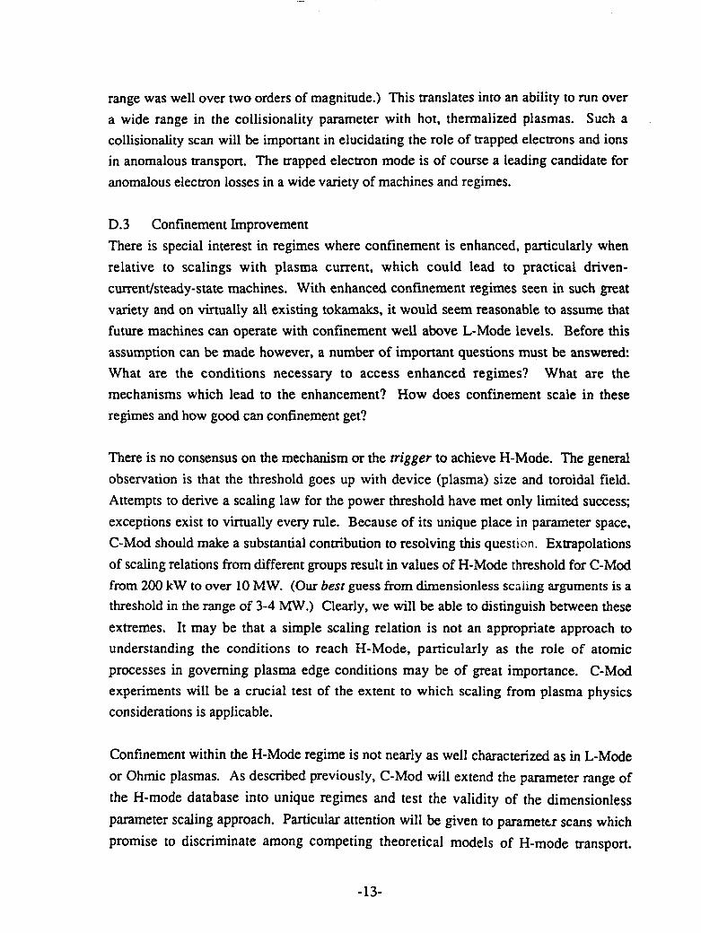
D.3 Confinement Improvement
There is special interest in regimes where confinement is enhanced, particularly when
relative to scalings with plasma current, which could lead to practical driven-
current/steady-state machines. With enhanced confinement regimes seen in such great
variety and on virtually all existing tokamaks, it would seem reasonable to assume that
future machines can operate with confinement well above L-Mode levels. Before this
assumption can be made however, a number of important questions must be answered:
What are the conditions necessary to access enhanced regimes? What are the
mechanisms which lead to the enhancement? How does confinement scale in these
regimes and how good can confinement get?
There is no consensus on the mechanism or the trigger to achieve H-Mode. The general
observation is that the threshold goes up with device (plasma) size and toroidal field.
Attempts to derive a scaling law for the power threshold have met only limited success;
exceptions exist to virtually every rule. Because of its unique place in parameter space,
C-Mod should make a substantial contribution to resolving this question. Extrapolations
of scaling relations from different groups result in values of H-Mode threshold for C-Mod
from 200 kW to over 10 MW. (Our best guess from dimensionless scaling arguments is athreshold in the range of 3-4 MW.) Clearly, we will be able to distinguish between these
extremes. It may be that a simple scaling relation is not an appropriate approach to
understanding the conditions to reach H-Mode, particularly as the role of atomic
processes in governing plasma edge conditions may be of great importance. C-Modexperiments will be a crucial test of the extent to which scaling from plasma physics
considerations is applicable.
Confinement within the H-Mode regime is not nearly as well characterized as in L-Mode
or Ohmic plasmas. As described previously, C-Mod will extend the parameter range of
the H-mode database into unique regimes and test the validity of the dimensionless
parameter scaling approach. Particular attention will be given to parameter scans which
promise to discriminate among competing theoretical models of H-mode transport.
-13-

Figure 1.3 shows the projected performance for C-Mod in nt-Ti space, under 4 different
confinement assumptions. An interesting feature of this plot is the drastic difference in
results when a Neo-Alcator term is added in quadrature with H-mode confinement.
Because of its very high current density, C-Mod will routinely run in regions of
parameter space where the L- and H-mode scalings predict confinement times greatly
exceeding those predicted for ohmic plasmas. The actual behavior of devices in this
regime has never before been investigated.
The second generic method for improving confinement comes from peaking the plasma
density profile. C-Mod will employ a 20-shot pellet injector which should be capable of
accessing this regime over wide ranges of target density and applied power. The standard
explanation for enhanced confinement in this regime is the suppression of ITG modes by
the short density scale length. While appealing and consistent with much data, there are
some serious discrepancies between experimental results and the ITG theory. Definitivetests may come by comparing experiment and predictions for both particle and impurity
confinement. It should also be possible to observe the ITG fluctuations directly with the
microwave reflectometer. With very peaked profiles, the ITG mode should be
completely suppressed. At reasonable densities, the large plasma current in C-Modshould provide operation with Xnc « Xe. This would allow us to isolate the electron
transport and possibly measure residual ion transport associated with electron modes.
D.4 Objectives of C-Mod Transport Program
The main objectives of thtC-Mlod transport physics program can be summarized as
follows:
* Test dimensionless scaling concepts.
* Investigate the threshold and properties for enhanced confinement regimes (H, VH,
P, IOC, Limiter Biasing/Er and combined regimes).
* Measure transport with strong applied RF heating.
* Test ITG and other drift wave theories.
* Correlate energy, particle, and impurity transport and investigate the importance of
off-diagonal transport matrix terms.
* Study the relationship between particle transport and the density limit.
* Attempt to determine whether electron transport is driven by electrostatic or
electromagnetic modes, or both.
-14-

E. RF Heating Program
The C-Mod RF heating program consists of two key elements: (a) ICRF heating with fast
magnetosonic waves at 80 MHz; (b) Long pulse (exceeding the L/R time) noninductive
current drive with lower-hybrid waves at 4.6 GHz. In addition to the heating and current
drive experiments, these systems will also be used to control temperature and current
profiles, and to explore access to enhanced confinement regimes.
E.1 ICRF Heating Program
The primary role of ICRF power in C-Mod is to provide the bulk auxiliary heating power
for carrying out the programs outlined elsewhere in this summary. Of particular
importance are studying transport and divertor heat load issues with ITER and reactor
relevant densities, magnetic fields, and plasma shapes. C-Mod can also test ICRF heating
at ultra-high densities, such as may be encountered in compact Ignitor-type devices.
ICRF heating will be carried out in both gas and pellet fueled discharges, and in both
inductively and non-inductively (LHRF) driven discharges. The ICRF power density on
the antenna surfaces will be high, up to 20 MW/m2 , which is in the reactor-relevant
regime.
E.2 ICRF Equipment
The transmitters for the initial operating phases consist of two 80 MHz FMIT units, each
operating at 20 MW, for a total source power of 4.0 MW. We also have two additional
transmitters on site, which could be refurbished if more power were needed. Given that
only about 75 - 80% of the source power is typically absorbed by the bulk plasma, at
least one of these additional transmitters should be refurbished for a total absorbed powerof 4-5 MW. The power from each transmitter is coupled to the plasma by a two-strap
antenna attached to the vacuum chamber wall. The straps may be operated either in-
phase (monopole) or out of phase (dipole), and the RF power density on the antenna is -
10 MW/m2 if one 2 MW transmitter is connected to each two-strap antenna. The
antennas can handle the expected RF and plasma heat loads for pulse lengths of at least
10 seconds. Based on code modeling, we expect good loading resistance for plasma
densities in the range from 1020 to 102 1m- 3, allowing coupling of the 2 MW of RF power
at RF voltages not exceeding 45 kV anywhere in the transmission line (including the
antenna itself).
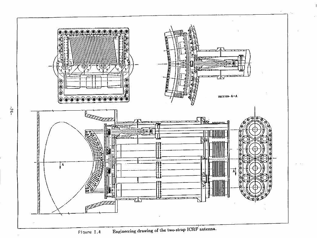
The design of the two-strap antenna is shown in Figure 1.4. The Faraday shield elements
are slanted and coated with TiC or B4C. To facilitate operational flexibility in the initial
-15-

phase of plasma operations, a movable, single strap (monopole) antenna will be used for
coupling studies. This antenna has already been fabricated and will be installed in the
machine before Phase I operations recommence, thereby giving us experience with
operating the ICRF system at the earliest possible date. The fabrication of the double-
strap antennas is well under way, and the antennas will be available for installation into
C-Mod prior to the start of Phase II.
E.3 ICRF Heating Regimes
Assuming a deuterium bulk plasma, the base operating scenarios will use toroidal fields
of 5.3 Tesla (H minority regime) and 7.9 Tesla (He-3 minority regime). Single pass
absorption is excellent for the H minority regime (- 90%) whereas in the He-3 minority
case it is typically about 20%. In past ICRF experiments, efficient heating has been
observed for single pass absorption of order of 5% or higher. High single pass absorption
is desirable for minimizing impurity generation. The slanted, coated Faraday shield
design should minimize impurity production at the antenna surface. Ultimately,boronization may be necessary for effective impurity control in an all metallic
environment such as in C-Mod.
In order to heat plasmas at even lower magnetic fields (higher 3), we find effective
heating scenarios at B = 3.95 Tesla (2nd harmonic He-3 minority, with approximately
20% single pass absorption) and B = 2.65 Tesla (2nd harmonic H minority; electron
Landau/TTMP regime). In summary, while transmitters with continuously tunable
frequency would be optimal, a wide variety of magnetic fields (2.65, 3.95, 5.30, 7.90 T)
are suitable for effective heating of deuterium majority plasmas for transport, current
drive and divertor heat load studies.
E.4 Advanced Tokamak Regimes with Lower Hybrid Current Drive
Utilizing the 4.0 MW, 4.6 GHz lower-hybrid system from the Alcator-C program, C-Mod
can access non-inductive operation regimes which are unsurpassed by any other existing
tokamak facility in the world. Of particular importance is the high effective current drive
power (P/R c I) and the long-pulse operational capability of the C-Mod magnet system at
fields of B < 5 Tesla, where tpulse 27 s. Owing to the small size of C-Mod, this pulse
length exceeds the L/R time (t ~ 4 s), even at Te- 5 keV, Zeff 2. To achieve the above
temperatures at central densities of 1020 m-3 , an H-mode factor of 2 is assumed.
-16-

The main hardware requirements tor achieving the LHCD options in C-Mod include an
upgrading of the power supply/modulator systems to long pulse (10 s) operation, and
fabrication and installation of a new grill/window array. The 16 klystrons are CW tubes,
each with output power of 250 kW, for a total of 4 MW source power. At present, half of
this system is on loan at PPPL and we expect that this equipment will be returned to MIT
in FY 94, after completion of the PBX lower hybrid experiments.
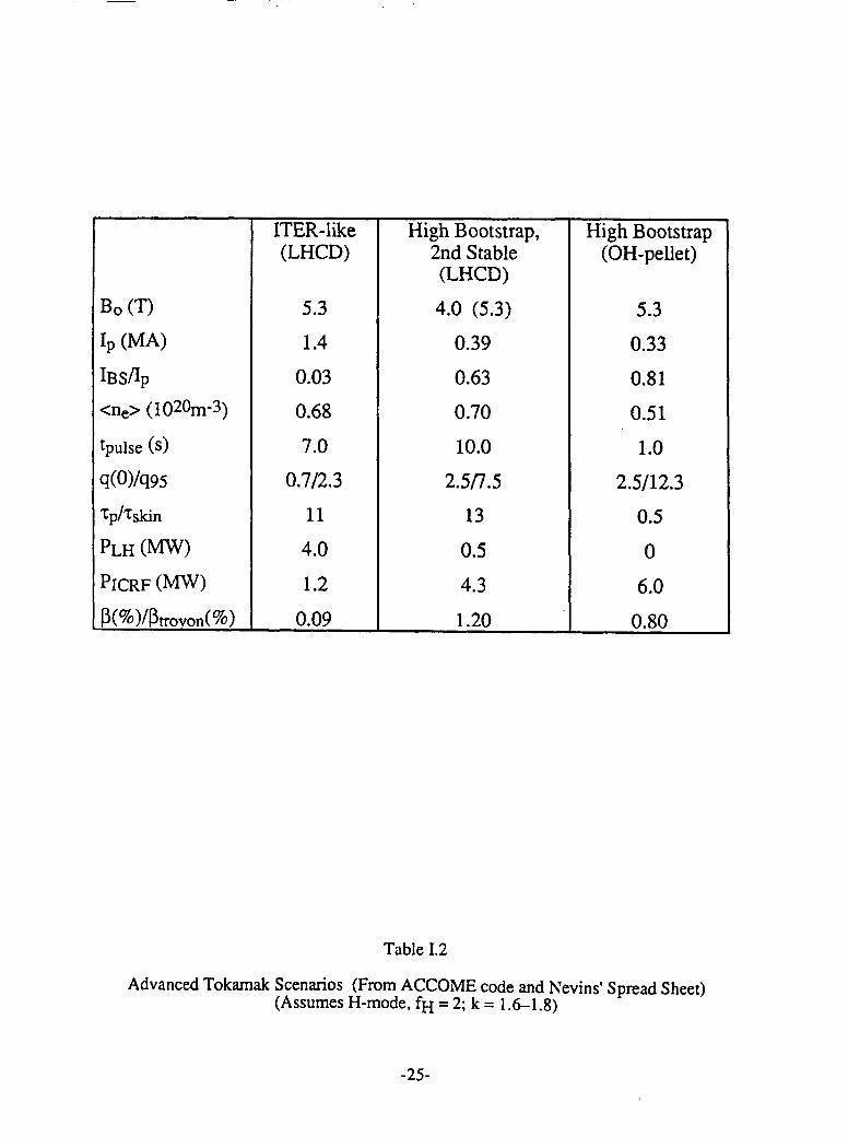
Table 1.2 summarizes several advanced tokamak regimes which have been identified by a
combination of the ACCOME code and/or Nevins' Spread Sheet (based on the ITER-89
formulary). For the sake of completeness, in Table E. 1 we also include a pellet-inductive
scenario which assumes a peaked density (pressure) profile, and hence a high bootstrapfraction (fBS > 80%) at low currents (high 3p) with intense ICRF heating. The diffusion
time of fast electrons is typically an order of magnitude longer than their collisional
slowing-down time.
We thus expect efficient current profile control using the lower-hybrid driven fastelectrons. Typical values of v* at the 80% flux surface are from 0.1 to 0.5, so the plasma
is sufficiently collisionless to test bootstrap current theories.
The following important scenarios may be noted in Table E.1:
* Confinement studies in noninductively driven plasmas with strong ICRF heating atITER-like parameters (ne= 1020 m-3, B = 5 T, Ip _ 1.5 MA, qW= 3, R/a - 3.3, tpulse
_ 10 tskin).* Tokamak operation and confinement studies with High Bootstrap Fraction (IBS/Ip >
0.6) at high £ 43p and tpulse = 10 tskin.
* Current profile control (with LHCD and high IBS) combined with ICRF heating,permitting C-Mod to operate in the 2nd stability regime (P > PTroyon for tpulse = 10
tskin* Combined LHCD and ICRF provides for synergistic current drive studies.* LHCD in C-Mod allows a quantitative study of fast electron diffusion (e < 100 keV)
under a wide range of plasma operational modes.
In summary, C-Mod is an excellent vehicle for studying advanced tokamak scenarios of
the type identified for TPX/SSAT. These studies would take place in the CY 1996 - 2000
-17-

time frame, thereby providing important information for optimizing the SSAT operating
scenarios.
F. Unique Features of Alcator C-Mod; Limitations, Schedule
F. 1 Features
Alcator C-Mod is at present the only tokamak in the world with a closed divertor and
with the capability to modify the divertor relatively easily. In view of the ITER relevant
plasma shape and heat fluxes, the device is ideal for studies of ITER divertor design,
including questions of the effectiveness of radiative and gaseous divertors. The high Z
divertor walls and metallic first wall also provide unique ITER relevant information.
The combination of high magnetic field, current, and mass density will allow unique
testing of the validity of the scaling laws used to project machine performance. The
availability of substantial amounts of ICRF power is essential in this task.
With the availability of LH current drive, Alcator C-Mod could also explore enhanced
performance tokamak regimes for about 10 current penetration, or skin, times. This
capability, although dependent on upgrades for LHCD, is unique in the period in which it
is planned to be done.
F.2 Limitations
The budget described in the next section does not include increased engineering or
technical staff, which might be necessary, or at least highly desirable, as extra hardware
and diagnostic capability becomes available.
The ICRF system does not, at present, include tunable power supplies, so that scans of
machine performance as a function of B will require only different heating scenarios. In
the earlier device, Alcator C, ICRF heating was not effective for plausible reasons. Thus,
final success of the ICRF heating on a high density device is not absolutely assured.
The small size of the device and divertor will cause some difficulties in accurate
diagnostic analysis of the scrape-off layer and divertor regions
F.3 Schedule
Since the preparation of the body of this report (June 1992) the date for the completion of
the repairs to ,he poloidal coil feeds has slipped one or two months. The start date of
October 1992 shown in Figure A.2 could slip to late November or December of 1992.
-18-

G. Budget
The group has layed out a program shown in Figure I.1 that costs $16.8 M per year. The
personnel costs of $11 M include roughly 18 physicists, 20 engineers, 30 technicians and18 graduate students, plus support staff. With operating costs of $3.3 M and $.9 M forsmall scale acquisitions approximately $1.6 M per year is proposed for capital equipment.Over a six year period it would be allocated as follows: upgrade of ICRF systems $2.0 M,LH systems $4.8 M, divertor biasing $.5 M, and testing of ITER prototype divertor$2.3 M.
-19-

1992 1993 1994 1995 1996 1997 1998
B S 5T B 9T B 9T B 9T IH <8MWI S 0.8MA I < 2.5MA I < 3.0MA I S 3.0MA LH 4MW
Kc5 1.5 K5 1.8 ic< 1.8 cS 2.2ICH < 2MW ICH < 4MW ICH5 <6MW ICH 8MW
LH < 2MW
I IIA IIB IA N IB IVA IVB
Ohmic, Full-field, Hi Power ICH, Opt. Divertor· s SOL & Radiative Gaseous &Tokamak
\ ICH divertor divertor & ImprovementStudies &ICH H-mode Studies Experiments
Physics
Repair oil; Insall Install Install Maint. & Insp.,Install Flywheel, FMIT #3 FMIT #4, Mod. DivernorICH Ant. Dipole Ant.'s LH grill
Limiter Ops, Radiative Divertor, Gaseous divertor, Design/buildShaped control, Power loading char., H-mode confinement, optimized divertor,
Shaped Div. ops, Compare open & Div. bias/pumping Advanced shapingOhmic Conf., closed divertors, I-limit studies, LH current driveICH coupling, ICH phyics, Shaping - high K Quasi-steadyPellet fuelling Transport scalings, state ops. with
L&H-mode studies divertor cooling
Figure I.1Schedule and physics program highlights for Alcator C-Mod, through CY 1998
-20-
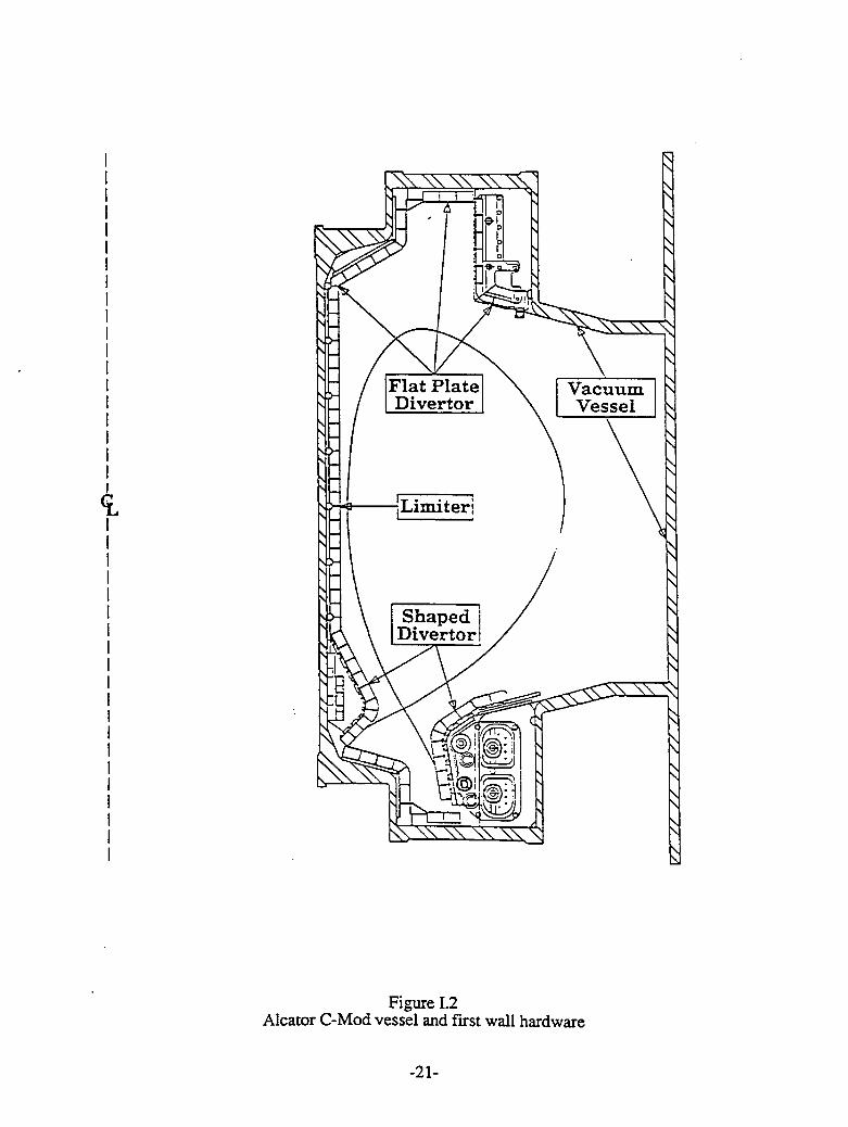
Flat Plate \ VacuumDivertor Vessel
'Limiter;
Divertorl / ^
Figure 1.2Alcator C-Mod vessel and first wall hardware
-21-

C-Mod ASDEX-U ASDEX-U DIII-D DIII- Machine XTest Actual Scaled DPoint from Actual Scaled
C-Mod fromC-Mod
a (m) .21 .5 .5 .67 .67 1.7
b (m) .38 .8 .9 1.3 1.2 3.1
R (m) .67 1.65 1.59 1.67 2.14 5.5
B (T) 8.0 2.7 2.7 2.0 1.9 .6
Ip (MA) 2.0 (<1.6) 1.6 (<3) 1.5 1.2
P (MW) 4 (<12) 2 (<20) 1.7 .8
ne (M 3) 6.0 (<1) 1.0 (<1) .6 .09(x 1020)
Table I. 1Values for nominal machire parameters and a proposed operating point for dimensionless
scaling experiments
-22-

2i
\ \ -
2xlTER89-P\ \"H-mode" \
o12 0 . \ \ \ \"VH" modeITER89-P \ \+NeoAlcator
neoTE-3eo E \ \ a -1.o
(m 3s)
2xITER89-Po ±9 \\+NeoAlcator
is
1i 1 100
T. (keV)
Figure 1.3Predicted plasma performance for Alcator C-MOD under different confinementassumptions. Parameters are Ip = 2.5 MA, BT = 9 T, (q/ = 3), auxiliary heatingpower 4 MW. Each curve is a density (neo) scan from 1 to 20 x 1020 m-3. For thecases including NeoAlcator losses, they are added in quadrature with the (scaled)ITER89-P transport. Whether or not NeoAlcator confinement can be exceeded makesa very great difference at the lower densities.
-23-
SECTION- A-A
IT^~ ~ ~ ~ ~~~· H--8- ITIr^
^ "^I .J ^ ^-^ T - - ' ' I- -- P---
/ / v 01110 1111- S 1 _
-r |!3_l^d III ~:
Ii q I. .4 E e o
Fiqure 1.4 Engineering drawing of the two-strap ICRF antenna.
ITER-like High Bootstrap, High Bootstrap(LHCD) 2nd Stable (OH-pellet)
(LHCD)
Bo (T) 5.3 4.0 (5.3) 5.3
Ip (MA) 1.4 0.39 0.33
IBS/IP 0.03 0.63 0.81<ne> (1020m-3) 0.68 0.70 0.51
tpulse (s) 7.0 10.0 1.0
q(0)/q95 0.7/2.3 2.5/7.5 2.5/12.3
Tp/Tskin 11 13 0.5
PLH (MW) 4.0 0.5 0
PICRF (MW) 1.2 4.3 6.0
P(%)/Ptrovon(%) 0.09 1.20 0.80
Table 1.2
Advanced Tokamak Scenarios (From ACCOME code and Nevins' Spread Sheet)(Assumes H-mode, fH = 2; k = 1.6-1.8)
-25-

n.ORNL Advanced Toroidal Facility
A. Background and OverviewA. 1 MissionATF was designed to demonstrate high-S, steady-state, disruption-free operation that
leads to a reactor-relevant configuration. The ATF program goals for FY 94 - FY 97 are:* demonstration of (p) > 4%, low collisionality, and improved
confinement for pulse lengths up to 30 s;* optimization of the stellarator configuration and operational
techniques for improvement of LHD performance and the designof a better D-T stellarator;
* development of steady-state power and particle handling.Only ATF has the combination of configuration flexibility, Pj capability, pulse length,access for power and particle handling, and ICRF heating capability to accomplish thesegoals. It is cost effective because ATF and most of its heating additions already exist. It istimely because ATF would provide data >5 years before the large ($400 M) JapaneseLHD stellarator, and could thus determine the next generation of reactor development.There is a window of opportunity in 1994-97 for ATF to make crucial contributions tothe development of the stellarator concept and to allow the U.S. to capitalize on thestrong world program at relatively low cost.
A.2 RationaleThe world stellarator program provides the only credible, timely alternative to the toka-mak in reactor development. In the tokamak area, a steady-state, advanced tokamak(SSAT) has been proposed in parallel with ITER as essential to the development of anattractive tokamak DEMO. In the stellarator area, ATF will perform a similar role indemonstrating a reactor-relevant mode of operation. In particular, ATF protects againstfailure of the tokamak program and offers a promising route to fusion developmentthrough development of a lower-aspect-ratio, sheared-magnetic-field stellarator reactor(the decision points shown in Fig. II.1).
Stellarators have demonstrated energy confinement times, scaling and keV temperaturessimilar to those in tokamaks at the same stage of development (Figure 11.2) andWendelstein VIIAS recently (June, 1992) achieved H-mode operation. Stellarators haveachieved beta ((fl)) up to 2% and have operated for up to 20 s. Now, it is essential to
-26-

validate projections of (/3) 4% and improved confinement at low collisionality. In
particular, dimensionless parameter modulation studies in ATF showed that confinementimproves with increasing /3 and decreasing collisionality v as TrE/grB c .3 v 2.
A.3 Stellarators as Reactors
Stellarators require no plasma current. This eliminates disruptions and their associated
engineering problems, greatly reduces the recirculating power requirements of a reactor,
and removes a serious physics constraint on optimization.
New stellarator reactor assessments (Lyon et al, presented at ANS Meeting in June, 1992)
using the same costing algorithms and unit values as in the ARIES-I tokamak reactor
study show that a stellarator reactor with same power output as ARIES-I could have
* similar major radius
* lower 6ost of electricity
* significantly higher mass utilization
* much lower magnetic field
as shown in Table II.1.
The magnet systems and associated structure are smaller for the stellarator reactor
because the helical coils are closer to the plasma, and both the helical and poloidal field
coils have smaller cross sections. The stellarator coil set, structure, and blanket can be
constructed of > 10 modules, with additional central access, thereby easing the
maintenance problem. Coil configurations can be designed to have low power density
external divertors and to avoid the accumulation of helium ash, while retaining acceptable
alpha particle heating.
B. Technical Objectives
The ATF program focuses on performance improvements and physics understanding
needed for developing an attractive stellarator reactor: (1) confinement improvement; (2)
reactor-relevant levels of beta; (3) low bootstrap current; (4) exploration of a
configuration and transport data base for extrapolation to larger devices; (5) development
of an efficient long-pulse heating scheme (ICRF); (6) acceptably low fast-ion losses; and
(7) steady-state capability (power, particle, and impurity handling). ATF is the only
existing stellarator that allows an integrated test of these physics issues.B. 1 Short-term program (<5 years)
-27-

The proposed 31/2 year experimental program for ATF in FY 1994-1997 is based on 1¥/2
years of preparation at low budget levels in FY 1993-94, as discussed in Section VI. The
main objective for ATF in FY 1994-1997 will be to: (1) demonstrate reactor-relevantparameters ((/) > 4%, low collisionality [v*helical 102 oroidal < 1 a d
helical 0 toroidal < 1], and -2improvement in confinement) in long-pulse operation (=30 s); and (2) optimize the
stellarator configuration (developing a reactor-attractive magnetic configuration and a
corresponding modular coil set for a possible D-T test step). Key elements of the physics
program are:
* stellarator optimization: physics of ICRF, ripple-induced
transport, minimization of the energetic-particle loss region,
effect of electric fields on rp and TE, and dependence of beta
limits on configuration properties;
* tests of neoclassical theory: bootstrap current and Ware pinch,
transport from stochastic fields and magnetic islands;
* anomalous transport: gyro-reduced Bohm scaling and separationof helically-trapped and toroidally-trapped particle instabilities;
and
* second stability: tests of the predicted high-/ confinement
enhancement (rE/rgrB 1P.3 V0 2) and exploration of the second-
stability regime under equilibrium conditions; stability of broad
pressure profiles.
This program would build on ATF's demonstrated physics base: configuration control, 3-self stabilization; the neoclassical nature of the bootstrap current and its control (and
reversal); and the correspondence between tokamaks and stellarators in edge fluctuations,
velocity shear layer, and transport. These contributions are indicated graphically in
Fig. 1.3.
B.2 Longer-Term Program (>5 years)
If successful, the next step (FY 1998- ) would be true high-power steady-state operation
of ATF to demonstrate steady-state power and particle handling and plasma control. If
this step were successful (and the data from LHD, W VII-X, ATF, etc. are sufficiently
encouraging), and the tokamak were not ready to proceed to a DEMO, then the stellarator
program would be ready to proceed with the development of a D-T Stellarator.
-28-
C. Special Features
C. 1 Uniqueness of ATF Contributions
ATF will remain the world's largest stellarator until the end of this decade when LHD
starts producing results, and is the only large stellarator in the U.S. program. ATF has
>2x the plasma volume and much greater interior access and port size than any other
stellarator and >2x the heating power and >10x the pulse length of any other sheared
stellarator. Even when LHD is in operation, ATF will have >2x the volume power
density in pulsed operation and could have >2x the heating capability and 10x the surface
power density of LHD in steady-state operation.
C.2 Place in the World Program
There are basically two routes to stellarator development: sheared systems such as
Heliotron-E, CHS, and ATF leading to LHD; and low-shear systems such as W VII-AS
leading to W VII-X. The sheared system is optimum at lower aspect ratio. Each system
has important reactor-relevant features, such as (1) > 5%, modularity, and a natural
divertor. The best system for development of the reactor must arise from the experimental
program. ATF was designed to complement, not duplicate, other stellarators in the world
program by testing MHD optimization principles. It has a magnetic configuration similar
to that in LHD, but with extra flexibility for optimization.
C.3 Other Special Features
ATF can access the widest variety of magnetic configurations of any toroidal experiment,
allowing independent control of shear, magnetic well, and trapped rarticle fraction for
fundamental toroidal physics studies. Dynamic configuration control allows access to
configurations not otherwise accessible. In addition, ATF is the only experiment capable
of exploring steady-state operation in the second-stable regime and the only U.S. toroidal
experiment capable of true high-power steady-state operation before SSAT.
D. Parameters and Limitations
Because of budget reductions, auxiliary heating levels (=1 MW) were far below the
designed level of 6-8 MW during the initial period of ATF operation (1988-91), and
development of particle and power-handling systems were delayed. Nevertheless, good
progress was made in achieving relevant plasma parameters and in demonstrating the 20-
s pulse-length operation, with detailed, time-dependent control of the magnetic
configuration important to the next phase of the program. Maximum parameters achieved(not simultaneous) were Ti(O) = 1 keV, Te(0) - 1.5 keV,ie = 2 x 10²⁰ m-3, TE = 30 ms,
-29-
and () - 1.7%. Sets of simultaneous plasma parameters for four different operating
regimes are given in Table H.2.
ECH plasma startup and busbar cooling presently limit ATF to operation at B = 1.9 T (5
s), B - 0.95 T (30 s), and B = 0.67 T (steady state). Using ICRF for plasma startup, as has
been done on other stellarators, would allow ATF to operate at fields between 0.5 T (for
maximum beta) and 2 T (for maximum confinement). Cooling of the main busbar from
the helical field power supply would allow steady-state operation at B up to 1 T.
ATF has an uncooled vacuum vessel, which limits the power to the vacuum vessel walls
to =100kW in steady-state operation and to 3-MW 20-s pulses every 10 minutes. There is
room to install water-cooled panels inside the vacuum vessel for steady-state operation at
higher power, but this is not planned for the 1994-1997 operating period.
The present levels of 0.4 MW of long-pulse (<30-s) heating and 1.8 MW of short-pulse
(0.3-s) heating are inadequate for an experiment of the size of ATF (3 m 3 plasma
volume). ATF plans call for short-pulse heating of 3.4 MW, long-pulse heating of 1.4
MW, and steady-state (>1 hour) heating of =0.1 MW at the start of operation in mid FY
1994. By October 1995, the short-pulse heating would be 8.4 MW and the long-pulse
heating would be 4.4 MW.
Figures 11.4 and II.5 show how ATF can reach the high-/ and low collisionality regimes
required to meet its physics objtctives. Figure 11.4 shows the plasma /3 as a function of
heating power for gyro-Bohm confinement and the expected enhancement TE/TgrB -
p0.3 v .2. Values of (3) > 4%-sufficient to test Pf self stabilization-are accessible even
with gyro-Bohm scaling. Note that for this plot we choose to operate at the maximum
density attainable in ATF,7imax= 1.3 nSudo, where isudo= 0.25(PB/a2R) 1/ 2. Figure 11.5
shows the central temperature and electron collisionality as a function of power. The
helical trapping regime (where instabilities related to helically trapped particles may
occur) is accessible even with gyro-Bohm confinement; with enhanced confinement, the
toroidal trapping regime (where instabilities related to toroidally trapped particles may
occur) also becomes accessible.
E. Current StatusATF is not operational at present. At the end of May 1991, an electrical short occurred
between two of the segments in one of the two large helical-field windings. A temporary
-30-
repair allowed ATF to operate in the Fall of 1991, but at reduced field and lower
repetition rate. Two spare helical segments are on hand to replace the damaged segments,
but ATF must be disassembled to install them. This disassembly was underway when it
was halted for lack of funds. ORNL estimates that it will take 4-6 months to finish the
repair in FY 1993.
The ATF group is now heavily involved in collaborations on different U.S. tokamaks
(DIII-D, PBX-M, TFTR) and Tore-Supra. Most of these people could return to ATF in
mid-FY 1994 without seriously compromising these collaborations.
F. Time and Cost to Complete ObjectivesF. 1 ATF Program, FY 93 - 97
Figure 11.6 shows the budget and schedule needed to carry out the research program
outlined in Section H. A detailed budget breakdown is shown in Table 11.3. This program
allows for 3 1/2 years of physics operation beginning in mid-FY 94. Prior to that, resources
are required to restore ATF to full operation. A more aggressive funding profile would
accelerate the ATF program by six months, as is shown in italics in Table 11.3.
The Fabrication budget provides for improved plasma heating capability (using heating
supplies already at ORNL) and installation of a module for edge particle and power
control tests for development of a stellarator divertor. A significant portion of the ATF
Operations budget, 3-5 M$/year, could be provided for outside collaborators. In the past,
US and foreign collaborators have contributed significantly to the ATF program,
supported both by their own funding and ORNL direct support of 0.5-1 M$/year.
F.2 Steady-State Upgrade
ATF was designed for steady-state operation. The coil systems and power supply can
operate steady-state at B = 1 T, but additional plasma heating and cooling is required. The
ATF Steady-State Project would cost an additional 25 M$ in capital investment (plus
-20M$ operating for three years) and have two phases. In the first phase (with 2-MW
heating capability): the power supply buswork and the helical-winding joint cooling
would be upgraded for 1 T operation; new, cooled panels would be added to the vacuum
vessel to handle 8-MW in steady state and the full divertor and pumping system would be
installed; and cooling would be added to the ICRF antennas and the BBC transmitters. In
the second phase, an additional 4-6 MW of steady-state ICRF heating would be added.
-31-
Each 2-MW increment would require an antenna, steady state transmitter, and
transmission line.
G. Appendix. Historical Background
During the past 10-15 years, there have been tremendous advances in stellarator research.
Notably, during the early 1980's experimental research on the sheared Heliotron-E
(Kyoto) and shearless W VII-A (Garching) showed confinement and beta similar to that
in tokamaks at the same stage of development. Subsequently, further experiments and
theoretical work, including an increased effort in the U.S. and the former Soviet Union,
showed that there could be attractive modular stellarator reactors.
The ATF was developed at ORNL with extensive national and international collaboration
to demonstrate these capabilities. During its operational phase from January 1988 through
October 1991, ATF amply demonstrated its potential to provide important answers for
stellarator development and the understanding of the fundamental toroidal physics. Broadcollaboration was an important feature of the program. However, exploitation of its full
capabilities was limited by successive reductions in budgets owing to changes in DOE
policy, as shown below in unescalated M$.
FY FY 198Y 198 FY 1989 FY 1990 FY 1991 FY 1992
19.3 17.7 16.2 12.8 8.2 0.4
-32-

TOKAMAKS STELLARATORS Other ATF W VII-ASTorsautons
NO0DIID., etC. -- ATF
NO/ ATFLongPulae <
Twoldal 4/ 30 ,1.x-2 xGi BAdvancd Toklmalk P hyO IO ATF Slady-SUt ./ .aD-T Buer (nER) LHD,. W VIIX NO
. l---- I --- .--- I ----el ATTF Steddy-Stt .1 NO j 5%,5 MiW.243xGrB _* W VII-X
YES Se
NO| STOP h-<> D-T TEST DT TEST
YESt ENO
I1--,--,--'--II 3S T O P I
, --- : ------- : -DEMO -DEMO
DEMO
(a) (b)
Fig. I.1. Plans for development of (a) steady-state toroidalfusion reactor,and (b) stellarator reactor option.
OATF / OJETO W7AS - - DIilX HELE / ISX-BA CHSO L2 L-mode1 01 HEL-DR -
x 10-2 -,^''(3() Ba). (b)
10- 10 -2
10 1O0 1 1 0- 10-3 1o2 101 1
Stoll 0.8 0.6 -0.6 2.4 0.6 -0.2 tok -2 0.8 0 6 -06 2.2 1.02 -0.2tgB (s)=0.25.BT .20 .PMw.am *KR m -A Tg8(S) 1.9 4 x10 21 *M 0 PV.am .(R/a) A
Fig. II.2. Comparison of energy confinement in stellarators and tokamaks (L-mode) using gyro-Bohm scaling. For ic= 1.4, R/a = 3, qcy = 3, (an "average" tokamak geometry), rEsfell= TE 'k
-33-
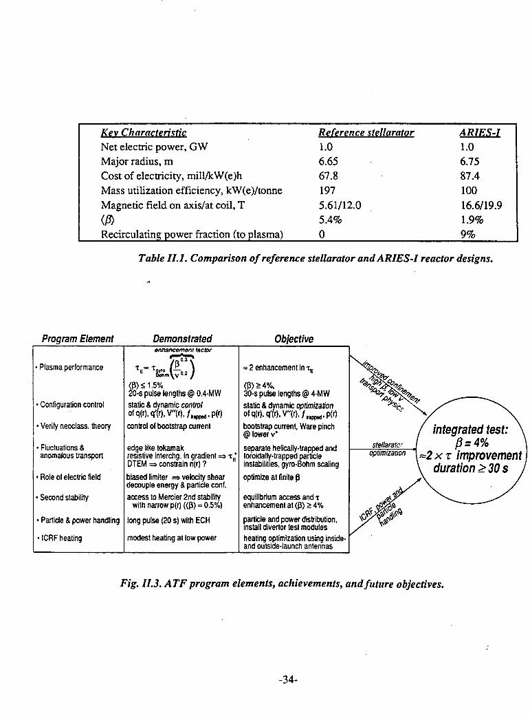
Key Characteristic Reference stellarator ARIES-INet electric power, GW 1.0 1.0Major radius, m 6.65 6.75Cost of electricity, mill/kW(e)h 67.8 87.4Mass utilization efficiency, kW(e)/tonne 197 100Magnetic field on axis/at coil, T 5.61/12.0 16.6/19.9
(P) 5.4% 1.9%Recirculating power fraction (to plasma) 0 9%
Table II.1. Comparison of reference stellarator and ARIES-I reactor designs.
Program Element Demonstrated Objectiveenhancement factor
Plasma performance E [ It l' = 2 enhancement in TE \ .
<< 1.5% > 4%,20-s pulse lengths @ 0.4-MW 30-s pulse lengths @ 4-MW o.. ,
* Configuration control static & dynamic control static & dynamic optimization i \of q(r),q(r). V"(r), f,,f .p(r) of q(r). q(r). V"(r). fP. p(r)
* Verify neoclass. theory control of bootstrap current bootstrap current, Ware pinch integrated test:@ lower v.
* Fluctuations & edge like tokamak separate helically-trapped and stellaratc' P=4%anomalous transport resistive interchg. in gradient = 'E toroidally-trapped particle ptimzaton =2 x r improvement
DTEM = constrain n(r) ? instabilities, gyro-Bohm scaling duration 2 30 s* Role of electric field biased limiter = velocity shear optimize at finite \
decouple energy & particle conf.* Second stability access to Mercier 2nd stability equilibrium access and '
with narrow p(r) ((p) 0.5%) enhancement at (p) > 4%Particle & power handling long pulse (20 s) with ECH particle and power distribution, \/'
install divertor test modules* ICRF heating modest heating at low power heating optimization using inside-
and outside-launch antennas
Fig. 11.3. ATF program elements, achievements, and future objectives.
-34-

High stored eneroy Hieh Low Long ECHshot #11740 #11186 #14514 #16654B (T) 1.9 0.45 1.9 0.95n, (1019 m-3) 11 4.3 0.53 0.5Pabs (MW) 0.96 0.98 0.79 0.25TE* (ms) 26 6.1 6.4 5Te(0) (keV) 0.4 0.3 1.0 1.0Ti(0) (keV) 0.4 0.3 1.0 0.2(/) (%) 0.4 1.7 0.08 0.15duration (s) 0.25 0.2 0.15 20
Table II.2. ATF parameters for four different operating regimes
7
n o = 1.3 nsudo
B (T) gB mod-gB enhanced5 0.63 _ _ gyro-Bohm
0.95 - -0.63 T
4
^ 3 3 _ \60, 0.95 T3 -
2 00.63T (Apr-90)¢ _ . j ---o gyro-Bohm
1 ~ 'i<=0.95T (Apr-90)
0 1 2 3 4 5 6P (MW)
Fig. 11.4. Expected plasma ,3 in ATF as a function of heating power for gyro-Bohmconfinement (thin lines) and for predicted enhanced confinement rE/r grB f 3 v-(thick lines). The solid points show achieved experimental values.
-35-

10 . i Fig. 11.5. Expected100 central temperature and
electron collisionality for1- : X^ helically trapped . helically trapped (vH*)
- _^ . helicallytrapped~10 and toroidally trapped.. ^------^- gyro-Bohm
I 0.1 - ___gyro-Bohm (VT*) particles as a*I 0.1 i s~ ~ _ ~~_^~ _^ _ _ _ _ _ _ 1 > ~ ~function of heating
toroidally trapped 4 - power in ATF for gyro-
_0. ~01 ~enhanced Bohm and enhanced0.01B = 1.5 T gyro-Bohm 0.1 confinement.n =3x10⁹m'3
0.001
3 _ -/ enhanced
'> gyro-Bohm.0
X 2 _
1 gyro-Bohm
0 1 2 3 4 5 6
P (MW)
-36-
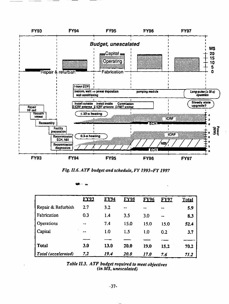
FY93 FY94 FY95 FY96 FY97
Budget, unescalated, M$
' ~Capitalci 'm '.iii - -20
Rpair & ref Fabrication 0
Installoutsids Install insids Commision a te
I I
~vess~el :9 3ChourEC\I_ 4
instwm. wall: = power deposition pumping moduleaLong-pulse(Ž30s)wall conditioning I opu s Ion 3
Flaassembly ) ---- ~-~ rECH --~~~~ECHNBI~' I IRInstall outside Install inside Commission Steady tate
Repair & Refurbish 2.7 3.2 -- -- -- 5.9
Repair | U IlCRF antenna JHICRF antenna UIFMITxmitter I
Fabrication 0.3 1.4 3.5 3.0 -- 8.3
Operations -- 7.4 15.0 15.0 15.0 52.4
acilital 1.5 1.0 0.2 3.7
Total 3.0 13.0 20.0 19.0 15.2 70.2
FY93Total (accelerated) 7.2 19.4 20.0FY95 FY9 6 FY97
TabFig. 11.. ATF budget and schedule, FY 1993-FY 1997objectives
(in M$, unescalated)
-37-
DIII-D
A. SummaryThe DII-D program proposes to address most of the key issues now emphasized in
tokamak fusion research: high-beta, high-confinement operation, noninductive current
drive with detailed profile control, enhanced pulse length, and elaborate divertor
application and testing. In other words, it intends to explore "advanced" tokamak
operation in a serious and extensive manner. A distinctive feature of the program is its
intent to attack these technical challenges in an integrated fashion, eventually applying
the various operational advances simultaneously. The point is not only to take advantage
of synergism, but also to provide the experimental information most pertinent to future,
larger tokamak devices.
These are obviously ambitious plans that cannot be presumed to succeed. Yet it is
notable that, in a nonintegrated and sometimes transient fashion, many of the planned
achievements have been approached or even exceeded in previous DIII-D experiments:
high beta and current profile control are two prominent examples. Indeed, the widely
admired DIIm-D accomplishments make its program plan appear well grounded.
B. Background and Overview
DIII-D, the fifth generation of magnetic fusion experiments operated by General
Atomics, is the largest non-circular tokamak in the US. It is operated with extensive
national and international collaboration, including a long standing Japanese collaboration
and multi-disciplinary collaborations with, among other institutions, LLNL, ORNL, and
UCLA. The DI-D program is being called upon to provide R&D results to the
engineering designs of the International Thermonuclear Engineering Reactor (ITER) and
the proposed toroidal plasma experiment (TPX). The DIII-D tokamak program is now
demonstrating, transiently, advanced tokamak operation in the form of high confinement
modes, second stability and large bootstrap current operation. Specifically, DIII-D has
achieved:
* high performance plasma operation with plasma betas exceeding those required
for a reactor,
* high-quality plasma confinement regimes (VH-mode, high inductance);
* increased first stability regime limits and tokamak operation in the second
stability regime;
-38-

* radio frequency heating and current drive that could provide for reactor current
profile control and steady-state operation;
* divertor heat load reduction and methods of impurity control that bear on steady-
state reactor operation.
The DIII-D long range research program focuses on divertor and advanced tokamak
issues. Its goal is to provide an integrated demonstration of well-confined high-beta
plasma with non-inductive current drive and effective divertor operation. Implementation
of this plan would obviously bear on ITER R&D issues, as well as possibly opening new
ITER operating options. In addition, it should identify engineering design concepts
pertinent to an electrical demonstration plant (DEMO).
The DII-D experimental plan and the schedule for implementation of new research tools
is indicated are Fig. III.1. The current and proposed parameters are shown in Fig. 111.2.
The proposed DIII-D program would use theoretical and technology advances to extend
the tokamak experimental physics database. Results from experiments at DIII-D and
other tokamaks indicate that plasma and divertor performance can be increased beyond
the baseline engineering design of ITER. A simultaneous demonstration of such
improved tokamak plasma and divertor operation could open a path to an attractive
DEMO, provide new operating options for ITER, and establish an advanced physics
foundation for the TPX program.
C. DIII-D Technical Objective and Goals
The Dm-D objectives and goals are based on extensions of DIII-D transient results.
They can, and should, be tested with enhancements to the DIII-D tokamak capability,
especially with regard to an extension of plasma duration beyond current profile and
particle/wall time constants. To assure that the near-term research results will benefit
ITER and TPX, it is planned to conduct experiments in an integrated fashion. That is, the
various advanced operation features are to be demonstrated simultaneously, at
sufficiently high temperatures to obtain reactor-relevant values of the appropriate
dimensionless plasma parameters.
The above issues provide the motivation for the DIII-D program objective: to carry out
an integrated, disruption-free long-pulse demonstration of a well-confined, high-beta
plasma. Confinement will be based on the simultaneous use of noninductive current
drive and an advanced plasma and divertor configuration. The reference scenario has an
-39-

ITER-relevant quantitative goal: to sustain a 2 MA plasma with 5% beta for 10 sec. This
goal is a step toward a steady-state tokamak with improved divertor operation.
Quantitative DIII-D advanced tokamak goals are guided by the ARIES reactor study,
which has quantified tokamak performance parameters that could lead to an attractive
reactor concept. These parameters-confinement quality, stability factor, divertor peak
heat-flux reduction factor, and bootstrap current fraction-serve as targets for DIII-D
advanced tokamak goals, and provide a basis to chart technical progress. Target
parameters for DIII-D research are specified in Table III.1. The goal is to simultaneously
achieve and sustain such parameters in DIII-D for times longer than the tokamak current
relaxation time.
Present results and understanding indicate that this goal can be achieved with upgrades to
the DIII-D current drive and tokamak capabilities.
D. DIII-D Research Plan
The DII-D tokamak is well suited to carry out the challenging divertor and advanced
tokamak research outlined above. DIII-D has operated reliably, in part because it is
relatively modem: in 1986 it was outfitted with a new vacuum vessel, new outer poloidal
field coils, and 5 sec pulse-length neutral beams. The DIII-D poloidal magnetic field
system can generate a wide range of plasma shapes. A digital control system allows these
shapes to be modified in real time, giving efficient access to a broad range of
experiments. The neutral beam system operates reliably with power levels up to 20 MW.
The DIII-D magnetic field is limited to 2.1 T, but the magnet set provides good access
for heating and diagnostic systems. The plasma diagnostic set is among the best in the
world, particularly in the plasma edge and divertor region. Thus, the existing DIII-D
facility is well suited for the proposed research and complements research being carried
out at other tokamak facilities.
Improved divertor and advanced tokamak results have already been obtained from DIII-
D, making prospects for the proposed research appear promising. Advanced divertor
experiments, which have demonstrated high pressures in the divertor plenum chamber,
bode well for particle control with divertor pumping. Simple gas puffing in the present
advanced divertor region has transiently reduced peak divertor heat loads by a factor of
five from an ITER-relevant level of 5 MW/m2 . Hence, it seems plausible that a ten-fold
reduction could be sustained with a more optimally designed radiative divertor
-40-
configuration. Fast wave electron heating and current drive experiments at the 1 MW
level, as well as 110 GHz ECH microwave heating experiments at the 0.3 MW level,
show efficient power coupling. These results all bode well for the proposed divertor and
advanced tokamak experiments at higher power levels.
The objective of the proposed research in advanced tokamak development is to establish
advanced operation through significant improvements in both the stability and
confinement limits, using localized rf current profile control, rf and neutral beam heating
for pressure profile control, as well as control of plasma rotation and of the plasma
boundary conditions. There are 3 goals: (1) building on recent experimental results,
achieved under transient and dynamic conditions, which show advanced tokamak modes
(including VH-mode, high inductance H-mode, high second stable core, and second
stable high bootstrap configurations); (2) experimental validation of the physics of rf
current drive and efficiency optimization, in order to develop and prove the tools needed
for advanced tokamak optimization; (3) combination of these efforts for active control
and optimization of the advanced tokamak modes, leading to a demonstration of fully
noninductive, high beta, actively controlled operation. The proposed rf systems (8 MW
of fast wave power plus 10 MW of ECH/LH microwave power) will provide the local
deposition and control needed for this research program. With the DIH-D neutral beam
system, the rf systems will provide full noninductive operation for 10 sec at the target
2 MA, 5% beta condition. In addition, the current profile control systems will provide
the flexibility to optimize advanced tokamak configurations and carry out fundamental
tokamak physics research.
The proposed divertor program concentrates on divertor power and particle control under
conditions relevant to ITER and future devices. The initial divertor research program will
be carried out with the existing advanced divertor configuration that includes particle
pumping and electrical bias capability. Experiments will concentrate on hydrogen
pumping, helium removal, impurity control, edge plasma, and divertor physics. Divenor
predictive code modeling and supporting theory will be benchmarked with detailed
diagnostic measurements. This should provide a reliable model for design of future
divertors. In 1995, a new configuration, called a radiative divertor, will be installed. It is
designed to disperse the divertor power over a broader surface area, reducing peak
divertor power flux by up to an order of magnitude when compared to present
conventional divertors. The first radiative divertor will be passively cooled and operate
for up to 10 sec. A later actively cooled configuration will allow experiments up to 60
-41-
sec duration. It is assumed here that ITER would pay for that upgrade. The rf power
levels and plasma conditions for the 2 MA, 5% beta, 10 sec integrated demonstration will
also provide a relevant test of divertor performance.
The experimental plan is shown in Fig. III.3. Each year's operating campaign is
characterized by simple physics objectives that will provide key information to next-
generation tokamaks (ITER, TPX, DEMO, Reactor). The cross-hatched periods indicate
the periods of research operations. Figures III.4 and III.5 show the experimental
programs and research objectives for the Advanced Tokamak and Divertor Development
programs. These objectives will be carried out with close coupling between theories,
experiments, and technology development to advance magnetic fusion research in such
critical areas as transport, stability, plasma-wall interaction, toroidal Alfven eigenmode
suppression, divertor physics, rf heating and current drive, and disruption control.
E. Advanced Tokamak Research
The DIII-D tokamak operates with thermonuclear performance approaching that of larger
tokamaks with many of the dimensionless plasma parameters equaling or exceeding those
required for ITER and the ARIES power reactor. However, these parameters are not
currently achieved simultaneously. Therefore, the goal of the future DIII-D high power rf
and advanced divertor programs is to achieve many of these parameters simultaneously,
and thereby demonstrate an integrated physics-engineering solution to ITER divertor,
disruption, and current drive issues.
A long-time thrust of the General Atomics fusion program has been aimed at production
of high beta plasmas and the development of theoretical understanding of plasma
stability. A measure of beta enhancement is called normalized beta 3n=P/(VaB), which
increases as the current profile is peaked.
The highest beta values achieved at DIII-D exceed those anticipated for ITER. In these
11% beta discharges, the central beta is 44% and the plasma center is calculated to be in
the second stability region, with the outer edge at the first stability limit. Future
experiments using high power rf current drive to control the current profile will aim at
broadening the central high beta second stability regime and maintaining this second
stability configuration for longer duration.
-42-
Using the neutral beam system, which injects up to 20 MW in one toroidal direction for
neutral beam current drive, DIII-D plasmas that enter the second stability regime do so
over most of the plasma radius. Up to 0.4 MA of non-inductive current drive has been
driven and poloidal betas of 5.2 have been reached.
The high power density DIII-D neutral beam system (1 MW/m 3) is also well-suited to
investigate toroidal Alfven eigenmodes (TAE modes). These dangerous modes are
predicted to be driven unstable by fusion alpha particles or high energy beam ions whose
speed exceeds the Alfven speed. Operating DIII-D at reduced magnetic fields decreases
the plasma Alfv6n speed to that of the 80 keV deuterium ions injected by the neutral
beams. These beam ions thereby simulate alpha particles. When the beam ion beta
reaches a few percent, TAE-mode magnetic fluctuations at 20 to 100 kHz are excited,
beam ions are ejected, and the thermonuclear fusion power production is reduced. This
provides an excellent opportunity to develop and demonstrate engineering design
solutions to stabilize TAE-modes. Theory predicts that stabilization can be implemented
on DIII-D and ITER by controlling the plasma current profile, the plasma shape, the fast
ion pressure profile, and the density profile. DIII-D already has plasma shape control and
is developing rf systems for plasma current profile control.
Significant progress has also been made in understanding plasma transport and
developing enhanced confinement modes. High performance VH- or H-modes are
regularly achieved and studied at DIII-D. The joint ASDEX/DIII-D JET H-mode study
has found that the plasma H-mode thermal energy confinement time increases
proportionally with plasma current, with major radius, and decreases with the square rootof heating power. DIII-D has shown that the confinement improvement in H-mode arises
from shear in the E x B driven edge plasma rotation suppressing turbulence. Tools to
control plasma rotation and to further increase confinement improvements are being
considered.
While the H-mode is considered the standard operating mode for ITER, recently DIII-D
has operated in the very high performance, or VH-mode, with confinement that is nearly
twice that of H-mode. The VH-mode was discovered in DIII-D following boronization.
It is characterized by a broader edge temperature pedestal. The DIII-D VH-mode resultsin two times higher thermonuclear triple product (nTT) than their H-mode discharges.
Otherwise many of the VH-mode characteristics such as current scaling and fluctuations
are similar to H-mode.
-43-
Development of localized rf heating and current profile controls to provide new tools for
heating, controlling, optimizing, and sustaining plasma stability and confinement is a key
element of the DIII-D program. Recent DIII-D results (as well as those from TFTR and
JET) have indicated the important role that the plasma current density profile plays in
plasma performance as measured by normalized beta or normalized plasma confinement.
A centrally peaked current profile is better than the broad current profile that is normally
generated with inductively driven ohmic current drive.
Four advanced tokamak operating modes have been generated in DII-D by control of the
current profile. The pulsed methods employed in the current DIII-D experiments are
limited in duration by relaxation of the current profile to the inductively-driven profile.
Current profile control using rf waves can be employed to sustain the advanced tokamak
configurations. Estimates of the required rf power levels are in the range of 10 to 20
MW.
DIII-D is developing two innovative and attractive rf heating and current drive
technologies; 110 GHz microwave electron cyclotron heating (ECH) and 30-120 MHz
radio frequency fast wave heating and current drive. The aim is to develop a physics and
engineering database for technologically-attractive and cost-effective systems for ITER
and as well as the tokamak DEMO reactor.
A 1.6 MW 60 GHz ECH system is being used for basic physics studies, such as
modulated transient transport, sawtooth and edge localized mode (ELM) stabilization,
plasma pre-ionization and startup, ECH current drive, and electron heating to aid fast
wave current drive experiments. The ECH-driven currents are consistent with theory and
extrapolate to a current drive efficiency of 0.2 to 0.3x10 2 0 A/W m 2 for ITER conditions.
Future DIII-D ECH experiments at 10 MW ECH power levels and higher frequency are
expected to drive MA-level currents at higher densities.
The next step in the DIII-D ECH program is construction of a 2 MW 110 GHz prototype
system using four 0.5 MW gyrotrons. Currently, one 0.5 MW system is under test at
DIII-D.
The second element of the DIII-D rf current drive and profile control program uses a 2
MW fast wave system, operating at the ion cyclotron resonance frequency (ICRF). ICRF
ion heating has long been recognized as efficient and effective, especially in large
-44-
tokamaks. A second important application of this available rf technology is being
pioneered in DIII-D, fast wave electron heating and current drive. The antenna is
designed to launch waves at a frequency for which no ion cyclotron resonances exist in
the tokamak rather than directly coupling to plasma ions. In this case, the fast waves heat
electrons by Landau damping and transit-time magnetic pumping. Fast waves are the
chosen current drive techniques for ARIES, and are identified as an alternative current
drive scheme for ITER.
Fast waves have long been recognized as attractive from an engineering viewpoint, albeit
lacking a physics database. DIII-D is now establishing this database using a 2 MW 30-
60 MHz system and a four-element phased array directional antenna. These experiments
are succeeding because DIII-D has sufficiently high electron temperature (boosted by
ECH) for the fast waves to be absorbed by the electrons. These new results now open an
additional engineering option for an ITER current drive system. In contrast to neutral
beam current drive, less technology development is required and fast waves do not excite
TAE-modes as do high energy ion beams.
The DIII-D fast wave current drive antenna was designed and fabricated by ORNL. It
has been extremely effective at heating electrons with heating efficiency equal to neutral
beam heating. In DIII-D experiments, H-mode plasmas are easily produced by fast wave
heating alone. Fast wave current drive experiments have yielded promising results.
Directional antenna phasing has been demonstrated and changes in sawtooth behavior are
as expected. Loop voltage drops are consistent with 0.1 MA of driven current. Future
fast wave experiments will be conducted at higher fast wave power with the addition of asecond 2 MW transmitter and with increased electron heating power from the 2 MW 110
GHz ECH system. On a longer time scale, the fast wave power will be increased to
8 MW for advanced tokamak and divertor research.
F. Divertor Development
Presently the ITER divertor is patterned after the DIII-D divertor configuration. While
satisfactory for DIII-D, the design is inadequate for ITER power handling. To address
these shortcomings, a DIII-D advanced divertor program is underway.
Two techniques to reduce the divertor power flux have been demonstrated on DIII-D.
The first is sweeping the divertor strike point to reduce the time average peak divertor
heat flux. The second involves injection of gas into the divertor. This technique has
-45-

reduced the peak heat flux by a factor of five, with little degradation of plasma
performance.
The present DIII-D advanced divertor consists of a continuous toroidal ring that can be
electrically biased to enhance plasma flow into its entrance slit. The baffled divertor
chamber will house a cryopump, to be operational in early 1993. Divertor pumping will
allow DIII-D to control the density of H-mode plasmas, operate at higher temperatures
where rf non-inductive current drive is more efficient, operate with a more severe and
realistic divertor environment, and carry out H-mode helium transport studies.
Plasma erosion of divertor materials is already measurable in DIII-D and is feared to be
critical to ITER. The Divertor Materials Exposure System (DIMES) being implemented
on DIII-D will allow in-situ experiments with various materials to be tested in ITER-like
conditions, including time-varying power pulses from edge localized modes and
disruptions.
The present DIII-D advanced divertor was built to maximize divertor flexibility while
minimizing the impact on the flexibility or capability of DIII-D. As a next step, a
radiative divertor will be implemented. This concept, demonstrated in Doublet III, aims
at ITER and reactor relevance by radiating the power to reduce divertor heat loads and by
decreasing the electron temperature to reduce the energy of particles striking the divertor
plates. A demonstration in a high power current driven tokamak would provide relevant
design data for ITER and DEMO. The radiative divertor will provide radiative heat
dispersal, impurity entrainment, fuel recycling control and pumping, helium exhaust, and
materials qualification. With adequate diagnostics, code development, modeling, and
benchmarking, DIII-D would become an integrated test bed for ITER divertor
development.
The ultimate step in the present DIII-D divertor program plan is installation of an actively
cooled divertor. It is assumed that ITER would fund this step.
F.1 FY 92-95 Program
During the period FY 92 - 95 the DIII-D research program will have completed:
Transient studies of advanced tokamak operating regimes (VH-mode, peaked-
current profile, high ebp, second stability.)
-46-
* Validation of current drive physics of fast wave and electron cyclotron with
medium power.
* Initiated active control and optimization of advanced tokamak configurations.
* Completed the advanced divertor program demonstrating deuterium and helium
pumping, plasma density and impurity control.
* Developed and benchmarked improved theories and models of divertor and
advanced tokamak operation.
* Completed construction of a radiative divertor.
F.2 Outlook for FY 96 - 98
During the period FY 96 - 98 the DIII-D research program will have completed:
* Completed demonstrations of active control and optimization of advanced
tokamak configurations.
* Demonstrated high performance non-inducting sustained plasma (5% beta at
2 MA for 10 sec.)
* Optimized non-inductively driven advanced tokamak operating modes.
* Completed radiative divertor physics development and initiated actively cooled
divertor operation.
G. Upgrade and Modifications Required
Completion of the DIII-D FY 95 - 98 program will require several upgrades and
modifications. In cost estimating, DIII-D assumed that the base program would continue
at the current level. This wiltllow the present ongoing projects to be completed, aging
components to be replaced for modifications to diagnostics, modernization of the
computer system, and establishing a remote experimental site. These are essential
regardless of any upgrades or modifications. These expenditures together with research
operating costs consume the base budget. To add new capability requires additional
funds. The DIII-D cost estimates are provided in FY 92 dollars. Here, it should be noted
that a continuation of the base program at the current funding level implies that the
present 18 week (per year) run schedule will be maintained. While the recent DIII-D
advances in plasma control and improvements in diagnostics and data acquisition have
permitted them to make optimal use of the available machine time, it is clear that answers
to the important physics and technology issues being addressed by DIII-D could be
provided on a greatly accelerated time scale if additional run time is provided. When
queried on this issue, the DIII-D senior staff responded that a 36 week schedule would
result in a doubling of the productivity and research output while still permitting the
-47-
required maintenance, upgrades and experimental planning to be conducted. Concerningcost, the addition of a few additional weeks would require approximately $300 k/week.An expansion to the full schedule would necessitate the hiring of additional staff resultingin a yearly cost of $15 M. One view that was emphasized by the DI-D staff (and sharedby the Reviewers) is that the proposed upgrades should not be compromised or deferredin order to provide increased machine time.
G. 1 Radiative Divertor InstallationDemonstration of ITER and DEMO relevant divertor power dispersal and reduction in theincident plasma temperature requires installation of a radiative divertor. This passivelycooled modification would incorporate particle baffling and pumping as well as electricalbias. A high triangularity double null configuration appropriate for advanced tokamakperformance is under consideration. Implementation will be as a joint LLNL/GA effortincorporating other advanced divertor program participants. The total estimated cost is$16.2 M, including costs of relocating existing diagnostics.
G.2 Fast Wave PowerThe upgrade of the fast wave power for advanced tokamak central current drive andincreased divertor power loading will necessitate the addition of two 2 MW commercialrf transmitters (30-120 MHz). The total estimated installed cost, including transmissionlines, and tuners, is $6.5 M. To increase the pulse duration capability of the present 4-element 2 sec ORNL antenna to a 6-element 10-20 sec antenna would cost an estimated$2.8 M. To increase the pulse length to 60 sec will require water cooled Faraday shieldsestimated to cost $4.6 M.
G.3 Increased Microwave PowerTo increase the microwave power for advanced tokamak current profile control to 10MW will require installing ten 1 MW 110 GHz gyrotrons that are currently underdevelopment at Varian. This is an upgrade of the original 60 GHz gyrotron systemcomprised of ten 0.2 MW. Currently, four units are being modified for 0.5 MW 110 GHzgyrotrons. DIII-D is now examining the possibility of using 3 MW of lower hybridpower and 6 MW of ECH gyrotron power. A decision point occurs at the end of FY 95as to the advisability of adding more ECH power or adding lower hybrid power. Thetotal estimated cost ranges from $11.5 M to $25.4 M, depending on the mix of ECH andLHH and the power level. The final decision will take account of cost, physics issues,
-48-
and the state of the technology development (primarily a gyrotron issue). Currently, DIII-
D is performing a detailed study of the various options.
G.4 Diagnostics
New diagnostics are essential for the radiative divertor and advanced tokamak programs.
The estimated costs are $2.0 M and $3.0 M, respectively.
G.5 Tokamak Long Pulse Upgrade
Several tokamak subsystems need to be modified in order to increase the tokamak pulse
length to 10-15 sec at 2 MA plasma current and 2T magnetic field. This upgrade will
also allow 60 sec operation at half current and field. This pulse duration will equal
several current diffusion time constants for advanced tokamak studies and the 60 sec
pulse length will equal several particle/wall time constants. Needed are additional
poloidal field power supplies, improved magnet cabling, utility transformers, and
increased water cooling capacity. The total estimated cost is $7.1 M for 10 sec and
$1.4 M additional for 60 sec.
G.6 Neutral Beam Long Pulse Extension
To increase the neutral beam system pulse length beyond 3.5 sec at 20 MW or 5 sec at 16
MW required upgrades of the beamline internal heat handling, water cooling, and power
supplies. Upgrading the neutral beam system to operate at 20 MW for 10 sec will cost
$8.1 M, and $3.8 M additional for 60 seconds.
G.7 Radiation ShieldingAdditional neutron shielding is required to carry out the envisioned active long pulse
divertor arindhigh performance advanced tokamak research program. Currently, DIII-D is
enclosed in a shield that reduces the radiation site-boundary radiation by a factor 300. It
is proposed to add an additional factor of five, to raise the neutron shielding factor to
1500. Based on experience with the installation of the present shield, DIII-D estimates
the additional shielding will cost $3.5 M.
G.8 Building Modifications
General Atomics will provide the building expansion required to accommodate the
improvement to the DIII-D capability described above.
-49-

H. DIII-D Special Features
Unique Capabilities of DIII-D
H. 1 The largest Operating US Tokamak in the Post-TFTR Era
The DIII-D divertor and advanced tokamak upgrades together with the strong national
collaborative program would provide the US with an internationally competitive
magnetic fusion tokamak facility until the operation of TPX and ITER.
H.2 Plasma Shape
The large number of individually controlled poloidal field coils has allowed studies of
plasma shape (elongation and triangularity with indentation to be explored) on
confinement and stability. This capability has also been exploited by positioning small
plasmas within different regions of the neutral beam injection footprint.
H.3 Variable Aspect Ratio
The flexible DIII-D magnetic coil set together with the large vacuum system allows a
range of aspect ratios 2.5<A<5.3 to be studied. This feature has been exploited for
confinement studies and could be used for advanced tokamak second stability studies.
Most experiments are performed at small aspect ratio with strong shaping.
H.4 Digital Plasma Control
DIII-D possesses the world's most advanced operating real time digital plasma control
system. Already plasma shape, neutral beam power, and fast wave antenna loading are
under active control. In addition, more than one experiment can now be performed on a
single tokamak discharge. Future work will include active current profile control and
disruption avoidance and control.
H.5 Biased and Pumped Divertor
The electrically biased divertor has been effective for particle control, divertor strike
point variation, non-inductive startup, and H-mode threshold control. Installation of
cryopump is to be completed in January 1993 for density control.
H.6 ECH Power
The present 2 MW 60 GHz ECH system has been effective in electron heating, sawtooth
and ELM suppression, non-inductive startup, electron heating, modulated transport
studies, heat pinch and transport studies, H-mode studies, current drive and profile
-50-
control. The 110 GHz upgrade to 10 MW will extend these studies to higher density,
temperature and plasma current regimes. Pressure and current profile control will be
applied to sustain and optimize advanced tokamak configurations.
H.7 Fast Wave Heating and Current Drive
The DIII-D fast wave ICRF system has pioneered direct electron heating and current
drive. This work is in collaboration with ORNL who built the 4-element phased antenna.
Experiments at the 1 MW level have shown heating efficiency equal to that of neutral
beams and have resulted in driven currents of 0.1 MA. This technique looks attractive for
TPX and needs to be demonstrated at power levels well above Ohmic.
H.8 Diagnostics
A diagnostic system with exceptional edge and divertor diagnostics is operational.
Particularly noteworthy is the multi-pulse, multi-laser Thomson scattering system, the
high-resolution, high-speed ion profile charge exchange recombination system, the multi-
point motional Stark effect current profile instrument and five fluctuation diagnostics
systems.
H.9 Collaborators
DIII-D is a highly collaborative effort. Half the scientific staff are from institutions other
than GA. They participate in program planning, experiment development and leadership,
and in communicating the results. The most long standing collaboration is with JAERI.
The three major US partners are LLNL, ORNL, and UCLA. Collaborating institutions at
DIII-D include: International Laboratories (JAERI, JET, ASDEX, TEXTOR, ToreSupra, T-10, TSP, and Compass), National Laboratories (LLNL, ORNL, SNLA, SNLL,
ANL, PPPL, INEL), and Universities (UCLA, UCSD, UCI, UCB, MIT, RPI, Cal Tech,Johns Hopkins, U. Md, U. Illinois., U. Paris, U. Washington, and U. Wisconsin).
I. Uniqueness of Contributions of DIII-D
DIII-D is dedicated to developing critical information pertinent to ITER, TPX and a
commercially attractive tokamak reactor, through an integrated program of advanced
tokamak and divertor operation. Its extensive poloidal field coils and digital plasma
control system provide exceptional flexibility to address a wide range of research topics.
Its advanced divertor and current profile control capability is unique: DIII-D is the only
div:rtor tokamak with ECH and fast wave current drive capability. The high power
neutral beam system allows TAE-mode studies to be carried out with shape and current
-51-
profile control. The vacuum and magnet system, together with unique diagnostics,
provide conspicuous opportunities for plasma disruption and mitigation studies.
I.1 Place in the World Program
DIII-D is the only device in the world proposing to simultaneously tackle the divertor and
advanced tokamak mission in an integrated manner. Simultaneous demonstrations will
be of major benefit to commercial fusion development; it is not clear that addressing
these issues separately offers more than academic interest.
DHI-D has been the pacesetter of ITER design through its active contributions to the
ITER Physics R&D. Because many elements of ITER are patterned after DIII-D, results
from DIII-D are directly applicable to ITER.
DIII-D is also exploring various operating modes of TPX: improved confinement,
second-stability, efficient steady state current drive and profile control, divertor power
dispersal and plasma cooling.
Two additional points deserve emphasis:
* The US has no other machine offering DIII-D's capability in advanced tokamak
and divertor operation;
* DIII-D can seriously compete with JET and JT-60U on the world front, in spite of
its smaller size and cost.
J. Dm-D Limitations
The current and proposed machine parameters of DIII-D are given in Fig. III.2. Its size
and current are roughly half that of JET and JT-60U. However, its flexibility allows
innovative confinement, stability, current drive and divertor experiments to be conducted.
The main limitation is the present low rf power levels (2 MW ECH and 2 MW fast wave
power), which are inadequate for a tokamak the size of DIII-D. Because these levels are
comparable to the ohmic heating levels, rf experiments, while of scientific interest, are
not sufficiently definitive for extrapolation to ITER or TPX; nor are they adequate to
sustain advanced tokamak configuration or to stress the divertor.
Another important DIII-D limitation is that the pulse length is at present limited to 3.5 to
5.0 seconds, although 10 second low plasma current (0.7 MA) and lo power (3 MW)
-52-
experiments are possible. The limited pulse length thus limits DIII-D divertor studies;
the proposed upgrades will fix this.
At the present time the outer wall is only partially graphite-covered, resulting in some
limitations on plasma operating mode and plasma purity. The outer wall will be covered
with graphite tiles in early FY 93.
K. DIII-D Current StatusOperational Status (as of 7/7/92)
K. 1 Pre-FY 93 Operation
The DIII-D is a flexible tokamak facility powered with neutral beams and rf systems
capable of addressing a wide range of physics and engineering research issues. DIII-D
began operation in 1986 and has had modest increases in capability in the past seven
years.
Graphite tiles provide armor on the inside wall, floor, and ceiling. The outer wall
presently is mainly armored with Inconel tiles. In early FY 93, the outside wall will be
armored with graphite to reduce metallic impurities in the DIII-D plasma. Recent
experiments have used boronization wall conditioning, resulting in a fivefold reduction of
carbon and oxygen impurities and a thirty-fold reduction in metallic impurities.
In order to develop techniques for active disruption avoidance, magnetic error
compensation coils and a high speed (0.1 msec) digital control system, to feedback
control currents in plasma shape and position magnets, are being implemented.
The DIII-D tokamak has been operating typically 17 to 26 weeks per year since 1986. In
FY 92, without reprogramming, DIII-D operations have been curtailed to 14 weeks.
Experiments run were in support of the long range DIII-D program goal as well as in
support of next generation tokamaks. Physics experiments include: transport, H-mode
physics, high-beta, rf heating and current drive, divertor, advanced tokamak development,
TAE mode control, disruption control, and operational issues of importance to ITER and
TPX. These experiments are carried out using the 20 MW NBI, 2 MW FWCD, and 2
MW ECH heating systems, the 400' C bakeable vacuum vessel, and the advanced
divertor configuration, with real-time digital plasma control, intershot boronization and
helium glow discharge wall conditioning.
-53-

The first 0.5 MW 110 GHz gyrotron system is undergoing testing at short pulse lengths
(30 msec). Pulses injected into DIII-D show electron heating with the expected
efficiency and at the expected location. Longer pulse (10 sec) gyrotrons are being
developed at Varian. Sockets, magnets, transmission system, and antennas are all
completed at DIII-D. These units are compatible with future 1 MW gyrotrons.
Fabrication of mode converters is awaiting Varian completion of the production 0.5 MW
gyrotron.
The advanced divertor baffle and bias system is operational and showing promising
particle control results. A 1 m 2 helium cryopump will be installed in early FY 93.
The 2 MW fast wave system is operational and a tilted Faraday shield is being installed.
A second 2 MW fast wave transmitter is being purchased and ORNL is building four
element antennas to be installed in the 0 and 180 degree midplane ports, presently
occupied by outboard limiters that will not be needed once the outer wall is armored with
graphite in the beginning of FY 93.
The neutral beams are operating reliably, although some high voltage transformers need
to be rebuilt, and the control system needs to be modernized. Minor beamline melting
occurs but serious damage is being avoided by careful monitoring and control.
The JET pellet injector is being modified by ORNL for installation in Summer 1993.
A new 150 liter/hour helium refrigerator will become operational in early 1993 to provide
helium for the neutral beamlines, advanced divertor, ECH gyrotrons, and pellet injector.
The computer systems are nearly saturated but handle the present data load (60
MBytes/slot). The hardware and software are becoming obsolete and therefore must be
modernized. A remote experimental site is being developed by LLNL to open DIII-D up
to off-site DIII-D users and to off-load data analysis from DII-D computers
The diagnostic system is generally mature and operational. Preliminary data have been
obtained from a Divertor Institute Materials Exposure System (DIMES) for divertor
materials testing and a lithium beam emission measurement. These diagnostics funded
by D&T and APP will become fully operational in FY 93.
-54-
K.2 Repairs Necessary
No repairs are necessary
L. DIII-D Schedules and Budgets
The DIII-D program plan for 1992-98 is given in Fig. III.1. The more detailed divertor
and advanced tokamak plans are given in Figs. III.4 and III.5. The projected budget
estimates assume a $41 M budget in FY 93 for GA, LLNL and ORNL. The cost of
upgrades and modifications are summarized in Table III.2 together with a funding profile
that is consistent with the program plan schedule of Fig. III.3. These costs are in FY 92
dollars. The $10.1 M cost to increase the pulse duration to 60 seconds is indicated by the
parentheses, and is not included in the $74.6 M total cost.
-55-

CGENERAL ATOMICS
DIII-D LONG RANGE PROGRAM FACILITIES CAPABILITIES
FY | 93 | 94- 95 . 96 I 97 I 98 99CY 93 I 94 I 95 96 97 98 99
Tokamak andNeutralB anm 5-sec Operation 10 to 20-sec Operation 60-sec OperationNeutral Beam
Divertor-Divert or ,Operate ADPConfiguration
,.
Construct Operate Radiative Divertor
Design Construct Acveoled
RF Power 2MW MW 6MW Operate MW FWCD
2 MW Operate 4 MW 10 MW ECH
Base Physics,Codes, Theory
Figure III.1

+ GENERAL ATOMICS
DIII-D CAPABILITIES ALLOW A WIDE RANGE OFRESEARCH AND TECHNOLOGY ISSUES TO BE ADDRESSED
OHMIC HEATING COIL
;il-- S IE- COITOROIDAL Present ProposedFIELD COILS
! < i e 9 - Major radius 1.67 m
PORT Minor radius 0.67 m
ACCESS Maximum toroidal field 2.2 T
! SB !^ i 1 5 ~Available OH flux 12 V-sec
[-!-- ~ I M ID ;~ I ^ Maximum plasma current* 3.0 MA 3.5 MA
11 / M X X WNeutral beam power (80 keV) 20 MW 28 MW
i I w A n >COIL & RF power (60 GHz) 2 MW
i [ / SUPPORT RF power (110 GHz) 10 MW
i. l^^@^^m ^ RF power (30-120 MHz) 2 MW 10 MW
i V-zYACUUM Current flattop 5 sec 10 seci'fV~ r^!.._! . VESSEL (divertor at 2 MA)
BIASABLE PUMPED! DIVERTOR BAFFLE * Divertor operation; Limiter operation of 3 MA
POLOIDL FD CS achieved.POLOIDAL FIELD COILS Fimnir! TTT 2

Table III.1
TARGET PARAMETER GOALS FOR DII1-D ADVANCED TOKAMAK OPERATION
ITER Best Achieved DI0-0 TargetCDA Design (Independently) (Simultaneously)
Confinement quality 2 3.4 4(H = TE/TITER-89P)
Stability factor 1PN = P/(lIaB)] 3 65 6
Divertor plate heat load dispersal 1 5 10(reduction factor)
Bootstrap current fraction 0.3 0.5-0.8 05
-58-

+ GENERAL ATOMICS
DIII-D LONG RANGE PROGRAM OBJECTIVES
MFY 93 I 94 | 95 I 96 I 97 I 98 99
CY 93 94 95 96 9 98 99
> Develop physics of Advanced Tokamak (AT) regimes (transient)
Demonstrate particle and Impurity control techniques (ADP)
Establish configuration for Radiative Divertor
Assess confinement and stability limits of AT plasmas
,cln*~~~ < ̂I~~~~> c Evaluate and optimize bootstrap current
,qp0~~ < )Validate FWCD physics and efficiency
Validate second harmonic ECCD
Demonstrate active current profile control
< Demonstrate sustained advanced tokamak configurations
Initiate Radiative Divertor operation
Initiate 8 MW FWCD operation
>Demonstrate nonlnductive p and I profile control
Demonstrate divertor power dispersal
Demonstrate AT operation with high current
Demonstrate 2 MA, 5% 1
Demonstrate long-pulsepower and particlecontrol
Figure III.3
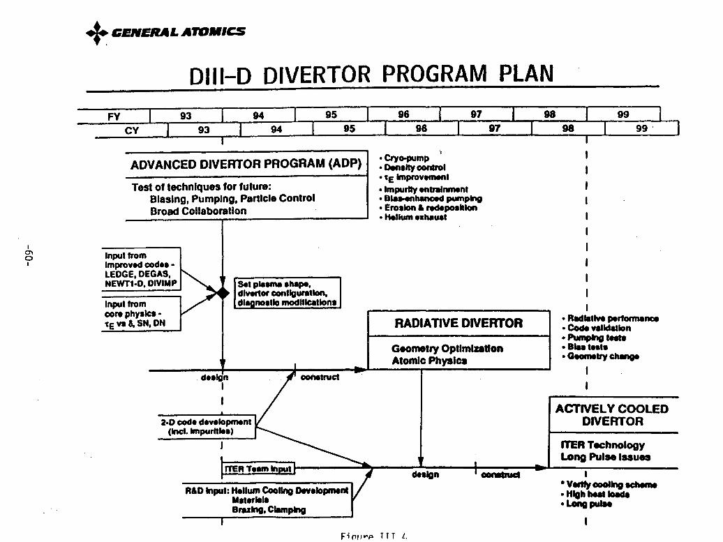
+ GENERALATMICS
DIII-D DIVERTOR PROGRAM PLANFY 93 94 95 96 i 97 98 i 99
CY i 93 94 95 9 96 97 98 99
ADVANCED DIVERTOR PROGRAM (ADP) :iySm"* E Improvnwnl
Test of techniques for fulure: · Impurity entrinmentBiasing, Pumping, Particle Control · BLae nhanoed pumpingBroad Collaboration Erosin & rdeposllon
CDI Input fromImproved codes *LEDGE, DEGAS, . __NEWrT-D. DIVIMP Set plawna shape.
divertor confguration.Input from I diagnosti modificatonscore physics - adtE v &^ SN. DN RADIATIVE DIVERTOR CosRdo dainb
' Pumping trt*Geometry Optlmlztlon - Bas tats
!__ , ___ I~ ~Atomic Physics GeOnltry chnge
deK sf oOnetruct
ACTIVELY COOLED2.D code developnmnt / IDIVERTOR
(hIcl. Impurlkie)J ~ ~ ~RI J^ ITER Technology
------- _ ^'^^^^^ \ Long Pulse Issuesam in* ' _______ deslgn ' oolwtruct
Vwey coolhg schemeR&D Input: Itollum Cooling D lovppnnt / \eltc olint g nc"
Materils .High hot loadsBr0 Clamping * Long pulse-B-,',,- . i.CT-npp IT .
FPim;io TTT zI.

DIII-D ADVANCED TOKAMAK (AT) PROGRAM PLANFY 93 94 | 95 96 97 98 , 99
CY | 93 1 94 1 95 96 97 1 98 99
TRANSIENT STUDIES OPTIMIZED NONINDUCTIVEOF IMPROVED REGIMES AT DISCHARGES
VH-mode, Peaked-Current, For DEMO design,High e bp, 2nd Stable +... ITER & TPX operatlon
· Shape dependence Demonstraton Demonte AT scenaros with fully· Explore 2nd stable regime emonstrat on nonlnductlve current drive· Evaluate & optimize Phase * Evaluate Improvements In stabilty and
bootslrap current confinement relative to reference discharge· Assess confinement & stability · Integrate & optimize AT scenarlos
limits of AT dischargesI__ ' ~ACTIVE CONTROL &
,------- - L_-. OPTIMIZATION OFUnderstanding AT CONFIGURATIONS Demonstration
& Validation PhasePhase Integration of stability,
#-_ confinement, andcurrent drive physics
Use rf to modify p and J profiles· Use external colls to control
rotation
VALIDATE CURRENT Full noninduciv operaton DEMONSTRATE HIGHat low currentDRIVE PHYSICS · Dlsniplion avoidance PERFORMANCE PLASMA
Cplirzallon of scenarios withMedium power tests Integrated active control High beta & high currentof FW & EC physics reference discharge
·Validate FWCD physics · 2 MA pluama currentValidate second harmonic ECCD physics · 5% beta
· Assess Impact of trapped electrons on 10 oecondsCD efficiency
· Evaluate bootstrap current Interaction with rl· Demonstrate density control
Figure 111.5

+ GENERAL ATOMICSTable III.2
COST SUMMARY FOR DIII-D UPGRADES IN FY92 $M
TotalCost FY93 FY94 FY95 FY96 FY97 FY98
Radiative divertor 16.2 2.0 * 7.0 7.2
Tokamak 7.1 1.0 2.0 2.0 2.1 (1.4)
Neutral beam 8.1 1.0 1.0 3.0 3.1 (3.8)
Fast wave 9.3 2.0 3.0 4.3 - - (4.9)
ECH 25.4 0 1.0 5.9 * 9.3 9.2
Diagnostics 5.0 1.0 1.0 1.0 2.0 0
Neutron shield 3.5 0 0 0 1.5 2.0
74.6 7.0 15.0 23.4 18.0 11.2 (10.1)
( ) = cost to upgrade to 60 seconds.* = decision point.

IVPBX-M
A. PBX-M Background and Overview
The PBX-M program is aimed at exploring two of the physics elements most important to
making an attractive tokamak reactor: an attractive operating regime characterized by high
beta, high confinement, and high self-driven currents; and avoidance of disruptions.
In their designs and experimental programs, PBX-M and its predecessor PBX have been
strongly driven by theoretical considerations, esp., in focusing on the second MHD-
stability regime as a potential reactor operating regime. Theory has suggested two
approaches to second stability: (i) providing strong inboard cross-section indentation for
qo - 1 (as in "bean shaping"); or (ii) employing non-indented configurations and holdingqo > 2. The former approach would be more attractive from a reactor viewpoint in
allowing higher beta, more bootstrap current and (possibly) reduction of certain transport-
inducing microinstabilities. The latter approach would be attractive in requiring a simpler
poloidal-magnetic coil arrangement. Having the capability to explore mixes of the two
approaches, PBX-M is positioned to determine the optimum.
Suppression of kink modes becomes more difficult at higher beta. Internal kinks can be
suppressed by increased triangularity, as in bean shaping. External kinks in PBX-M can
be controlled for moderate time scales by its close-fitting conducting 11. Longer-time
external kink avoidance will require control of the current and pressure profiles, together
with other active/passive techniques. For example, use the ponderc notive force of theion Bernstein wave has been suggested and will be explored. Similarly, disruptions
brought on by MHD activity should in principle be controllable by the same techniques
of profile modification, possibly combined with active/passive means, although a detailed
scenario has not been demonstrated.
Avoidance of MHD modes can be explored in PBX-M only for pulse lengths of 1-3 sec. (the
latter with minor facility modifications). At best, these only approach the L/R time scale for
current relaxation, or several (-5) times scales for profile adjustment.
In experimental program, the PBX-B has benefited from a number of productive
collaborations with other institutions. Both in degree of these collaborative efforts and the
degree to which the groups are integrated into the PBX-M team and its program planning,
-63-

PBX-M is prototypical of the "national-facility" type of organization anticipated for
TPX/SSAT.
B. PBX-M Mission, Technical Objectives and Results
The PBX-M mission focuses on the second stability regime and disruption-free operation. In
the short term (FY 92 - 95), the goal is to explore stability, confinement, and self-driven
current in the second stability regime. Capabilities to achieve these goals include current and
pressure profile control, plasma shaping, passive stabilization, and high aspect ratio
operation. The longer term (FY 96 - 98) program is disruption-free, second-stability
operation for times longer than the profile relaxation time. Both missions would provide
timely input into SSAT and other future advanced tokamaks. Below are presented results
from pre-FY 92 and plans for FY 92 - 95 and FY 96 - 98.
B. 1 Pre-FY 92 Operation
The original PBX performance was limited by external kink-driven disruptions, resulting in amaximum Pt of 5.5% and defining the basis for the ensuing upgrade, PBX-M. The major
upgrade changes were to increase major radius to allow greater indentation (30% in PBX-M
vs. 20% in PBX) and higher aspect ratio (from 4.7 to 5.5), to provide for a closed divertor
region for impurity control and optimized H-mode operation, and to install a close-fitting
conducting wall for stabilization of the external kink. Coarse current-profile modification
was to be affected by current ramping, neutral beam injection, L-mode to H-mode transitions,and pellet injection. The first stage of the PBX-M program examined transient high-P t
equilibria with regard to internal modes and conducting shell stabilization of external kinks.
Highlights of the pre-FY 92 operating period of PBX-M include:- Achievement of second stability in the outer 40% of the plasma volume with qo < 1
-Internal kink (fishbone) suppression by shaping and current profile control-Passive plate stabilization of the external kink at high t.
Simultaneous achievement of high TE/E-ITER-P (=3-3.5) and J/(I/aB) (=4-4.5)
- High value of Pt(R/a) = 37% for tokamaks, signifying a high level of stability at high
current density (low q).
-Suppression of low-n MHD modes by pellet injection
-Control of qo with counter-neutral-beam injection.
During this period, however, plasma performance was limited by low-n internal modes athigh P t and by low-n external modes at high Upo,. Theory indicates that both limitations can
-64-
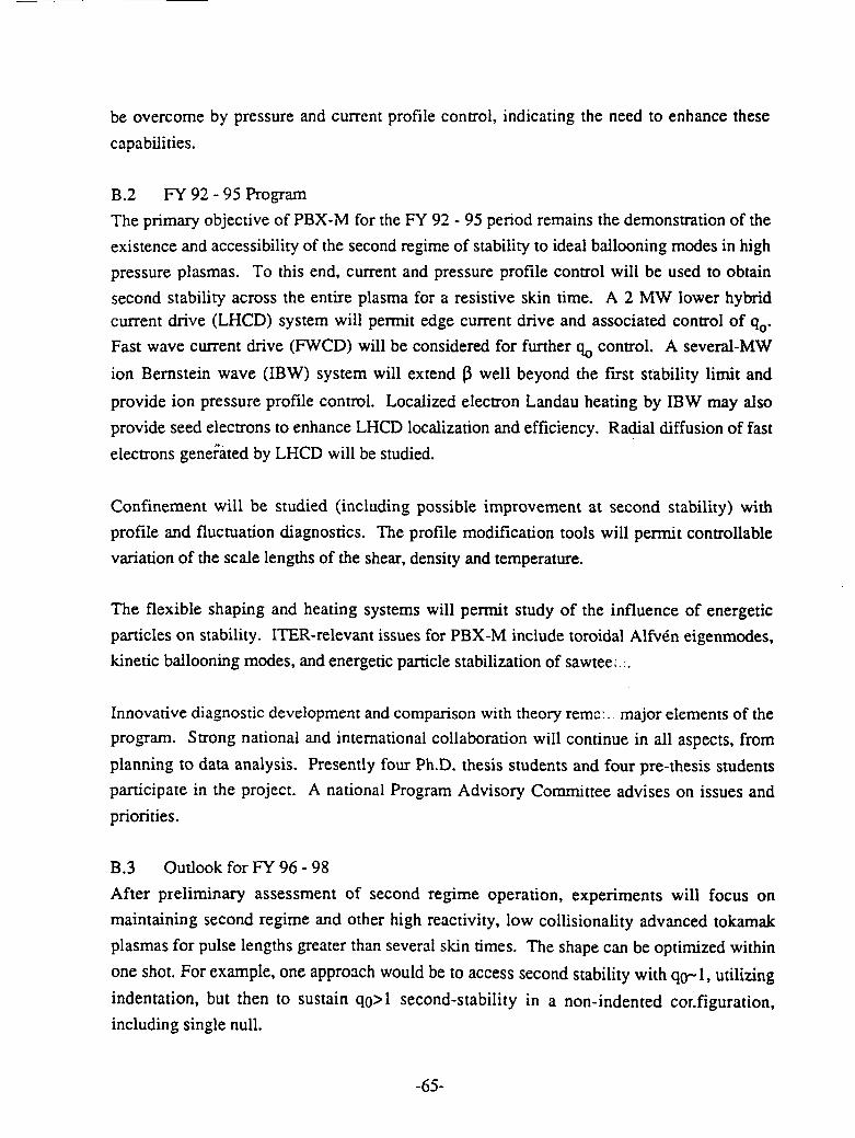
be overcome by pressure and current profile control, indicating the need to enhance these
capabilities.
B.2 FY 92 - 95 Program
The primary objective of PBX-M for the FY 92 - 95 period remains the demonstration of the
existence and accessibility of the second regime of stability to ideal ballooning modes in high
pressure plasmas. To this end, current and pressure profile control will be used to obtain
second stability across the entire plasma for a resistive skin time. A 2 MW lower hybridcurrent drive (LHCD) system will permit edge current drive and associated control of q%.
Fast wave current drive (FWCD) will be considered for further q0 control. A several-MW
ion Bernstein wave (IBW) system will extend P well beyond the first stability limit and
provide ion pressure profile control. Localized electron Landau heating by IBW may also
provide seed electrons to enhance LHCD localization and efficiency. Radial diffusion of fast
electrons generated by LHCD will be studied.
Confinement will be studied (including possible improvement at second stability) with
profile and fluctuation diagnostics. The profile modification tools will permit controllable
variation of the scale lengths of the shear, density and temperature.
The flexible shaping and heating systems will permit study of the influence of energetic
particles on stability. ITER-relevant issues for PBX-M include toroidal Alfven eigenmodes,
kinetic ballooning modes, and energetic particle stabilization of sawtee:.
Innovative diagnostic development and comparison with theory rema:. major elements of theprogram. Strong national and international collaboration will continue in all aspects, from
planning to data analysis. Presently four Ph.D. thesis students and four pre-thesis students
participate in the project. A national Program Advisory Committee advises on issues and
priorities.
B.3 Outlook for FY 96 - 98
After preliminary assessment of second regime operation, experiments will focus on
maintaining second regime and other high reactivity, low collisionality advanced tokamak
plasmas for pulse lengths greater than several skin times. The shape can be optimized within
one shot. For example, one approach would be to access second stability with qo-l, utilizing
indentation, but then to sustain qo>l second-stability in a non-indented cor.figuration,
including single null.
-65-

Complete disruption avoidance will be a major goal. Techniques include an integrated
passive shell/active coil feedback scheme, and fine current and pressure control on short time
scales. Both coil and profile feedback requires development of an advanced active plasma
control system, perhaps using a neural network. The long pulse length (-3 sec) is possible
with the present facility, although LHCD and IBW systems must be upgraded. The increased
duration will facilitate confinement and power handling studies, although the emphasis will
remain on MHD issues.
C. Upgrades and modifications Required
Completion of the PBX-M FY 96 - 98 program will require the following upgrades and
modifications in order to test long-pulse, disruption-free operation:
C. 1 Long-Pulse Capability: Plasma Operation
Flattop currents up to 600 kA are presently accessible for up to 3 sec (the shortest plasma
skin time, from the Mikkelsen '89 formula, is 0.3 - 0.5 sec). To study self-driven currents a
low collisionality requires a toroidal field of 2 T, at a cost of $0.4 M for minor repairs of
some motor generators.
C.2 Long-Pulse LHCD
To upgrade the 2 MW LHCD system from 0.5 sec to 2 sec (for a 3 sec plasma duration)
requires component modifications and exploitation of additional PPPL power supplies at an
estimated cost of $0.5 M. For increased flexibility in profile control an additional 2 MW is
desired, costing $4 M using existing MIT/LLNL components or $7 M if completely new.
C.3 Long-Pulse NBI
Upgrading the NBI from 0.5 sec to 2 sec requires installation of active cooling of the power
handling surfaces at an estimated cost of $5.0 M (including various ion source and
instrumentation improvements).
C.4 Advanced Active Plasma Control System
The existing analog plasma control system is now being replaced by a fast digital system,
modeled after a new DIII-D system. This will greatly increase the number of input signals
used to analyze and control the plasma. Finer control of the plasma shape and divertor
geometry will be possible. Further feedback control upgrades will use parameters
-66-
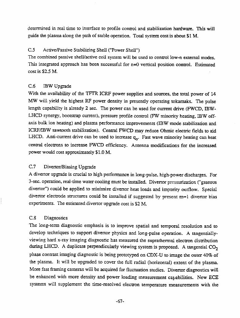
determined in real time to interface to profile control and stabilization hardware. This willguide the plasma along the path of stable operation. Total system cost is about $1 M.
C.5 Active/Passive Stabilizing Shell ("Power Shell")The combined passive shell/active coil system will be used to control low-n external modes.This integrated approach has been successful for n=0 vertical position control. Estimatedcost is $2.5 M.
C.6 IBW Upgrade
With the availability of the TFTR ICRF power supplies and sources, the total power of 14MW will yield the highest RF power density in presently operating tokamaks. The pulselength capability is already 2 sec. The power can be used for current drive (FWCD, IBW-LHCD synergy, bootstrap current), pressure profile control (FW minority heating, IBW off-axis bulk ion heating) and plasma performance improvements (IBW mode stabilization andICRF/IBW sawtooth stabilization). Central FWCD may reduce Ohmic electric fields to aidLHCD. Anti-current drive can be used to increase qo. Fast wave minority heating can heat
central electrons to increase FWCD efficiency. Antenna modifications for the increasedpower would cost approximately $1.0 M.
C.7 Divertor/Biasing Upgrade
A divertor upgrade is crucial to high performance in long-pulse, high-power discharges. For3-sec. operation, real-time water cooling must be installed. Divertor pressurization ("gaseousdivertor") could be applied to minimize divertor heat loads and impurity outflow. Specialdivertor electrode structures could be installed if suggested by present m=l divertor biasexperiments. The estimated divertor upgrade cost is $2 M.
C.8 Diagnostics
The long-term diagnostic emphasis is to improve spatial and temporal resolution and todevelop techniques to support divertor physics and long-pulse operation. A tangentially-viewing hard x-ray imaging diagnostic has measured the suprathermal electron distributionduring LHCD. A duplicate perpendicularly viewing system is proposed. A tangential CO2
phase contrast imaging diagnostic is being prototyped on CDX-U to image the outer 40% ofthe plasma. It will be upgraded to cover the full radial (horizontal) extent of the plasma.More fast framing cameras will be acquired for fluctuation studies. Divertor diagnostics willbe enhanced with more density and power loading measurement capabilities. New ECEsystems will supplement the time-resolved electron temperature measurements with the
-67-

multi-pulse TVTS diagnostic during long pulses. The neutral probe beam pulse length willbe extended for current profile measurements with the motional Stark effect system. Extrachannels are planned for the beam emission spectroscopy and poloidal rotation diagnostics.More CAMAC hardware and workstations will be obtained to accommodate theseenhancements. The total cost is about $2.8 M.
D. PBX-M Special Features
Unique Capabilities of the PBX-M ExperimentD. 1 Dedicated Experiment
PBX-M has the dedicated mission of advanced-tokamak, second-stability studies. It can testdifferent "trajectories" from first to second stability (e.g., low qo/high-indentation to highq(/no-indentation). Three new diagnostics are being developed to study the distribution andtransport of fast electrons produced by LHCD.
D.2 High Plasma Indentation
PBX-M plasmas can be produced with inboard indentation of up to 30%, predicted to lead toenhanced MHD stability. Strong indentation should allow access to second stability withnaturally occurring current densities (q = 1), as opposed to the approach through strongcurrent profile control with qo > 2. It has already been demonstrated that bean shapingsuppresses low-n "fishbone" oscillations.
D.3 High Aspect Ratio
The PBX-M aspect ratio of 5.5is the highest of presently operating tokamaks. High aspectratio has two advantages with regard to second stability. First, the 5 value and power neededto reach second stability decreases with increasing R/a ([ at R/a = 5.5 is about half of that atR/a = 3). Second, the unstable gap between the first and second regimes decreases withaspect ratio. High aspect ratio also yields improved confinement and stability in the firstregime (see Pre-FY 92 Operation).
D.4 Lower Hybrid Current Drive and Profile ControlThe LHCD system (2 MW @ 4.6 GHz) is the primary tool for current profile control. To doso, it is necessary to tailor the deposition profile of LH waves. This is achieved by a uniqueLH system which can change dynamically the phase velocity of the waves on a millisecondtime scale. Each of 32 wave guides is phased independently, allowing a wide range ofwavelength spectra. Experiments on time-varying phase velocities have already been carried
-68-
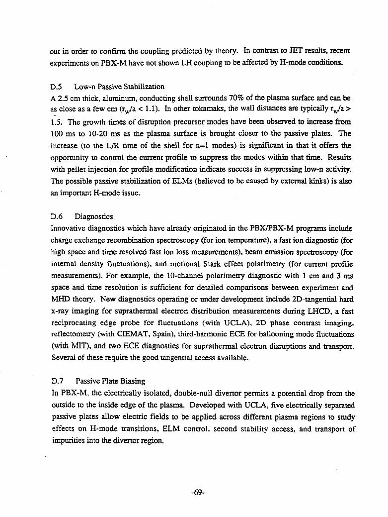
out in order to confirm the coupling predicted by theory. In contrast to JET results, recentexperiments on PBX-M have not shown LH coupling to be affected by H-mode conditions.
D.5 Low-n Passive StabilizationA 2.5 cm thick, aluminum, conducting shell surrounds 70% of the plasma surface and can beas close as a few cm (rw/a < 1.1). In other tokamaks, the wall distances are typically rw/a >
1.5. The growth times of disruption precursor modes have been observed to increase from100 ms to 10-20 ms as the plasma surface is brought closer to the passive plates. The
increase (to the L/R time of the shell for n=l modes) is significant in that it offers the
opportunity to control the current profile to suppress the modes within that time. Resultswith pellet injection for profile modification indicate success in suppressing low-n activity.The possible passive stabilization of ELMs (believed to be caused by external kinks) is alsoan important H-mode issue.
D.6 DiagnosticsInnovative diagnostics which have already originated in the PBX/PBX-M programs includecharge exchange recombination spectroscopy (for ion temperature), a fast ion diagnostic (forhigh space and time resolved fast ion loss measurements), beam emission spectroscopy (forinternal density fluctuations), and motional Stark effect polarimetry (for current profilemeasurements). For example, the 10-channel polarimetry diagnostic with 1 cm and 3 msspace and time resolution is sufficient for detailed comparisons between experiment andMHD theory. New diagnostics operating or under development include 2D-tangential hardx-ray imaging for suprathermal electron distribution measurements during LHCD, a fastreciprocating edge probe for fluctuations (with UCLA), 2D phase contrast imaging,reflectometry (with CIEMAT, Spain), third-harmonic ECE for ballooning mode fluctuations(with MIT), and two ECE diagnostics for suprathermal electron disruptions and transport.Several of these require the good tangential access available.
D.7 Passive Plate BiasingIn PBX-M, the electrically isolated, double-null divertor permits a potential drop from theoutside to the inside edge of the plasma. Developed with UCLA, five electrically separatedpassive plates allow electric fields to be applied across different plasma regions to studyeffects on H-mode transitions, ELM control, second stability access, and transport ofimpurities into the divertor region.
-69-

D.8 Ion Bernstein Wave Heating
The present system is 2 MW at 40-80 MHz for 2 sec., upgradeable to 14 MW using the
TFTR ICRF power supplies. Uses of IBW include bulk ion heating (without the fast tail
produced by ICRF), off-axis ion heating for pressure profile control, electron pre-heating for
increased LHCD efficiency, ponderomotive force stabilization of low-n edge modes, and
core transport reduction through ponderomotive-induced velocity shear. Experiments on
PBX are designed to overcome difficulties with IBW encountered elsewhere. Preliminary
low power results indicate effective ion heating. Activity in IBW/ICRF antenna
improvement includes boron-nitride-coated Faraday shields to reduce RF edge currents, and a
folded waveguide launcher to reduce RF electric fields near the plasma edge. Conversion
from IBW to ICRF (for heating or FWCD) requires a new antenna.
E. Uniqueness of PBX-M Contributions
PBX-M is a tokamak dedicated to, and uniquely positioned to focus on, the attainment of
second stability through the combination of bean-shaping and current profile control.
Although others are proposing second-stability studies employing the unindented, high-qo
approach, no machine in the world today offers the PBX-M flexibility, especially in its
exploration of extreme indentation and the qo/triagularity tradeoff.
The PBX-M aspect ratio of 5.5 positions it outside the range of 2.5-3.0, common in today's
tokamaks having similar performance. Higher aspect ratios have been identified as a
promising improvement path for tokamaks, requiring lower current for the same
confinement, possible relieved divertor heat load issues, and easier access to second stability.*6|K- ·- *,4
The very flexible lower-hybrid system in PBX-M permits dynamic preprogrammed or, with
modifications, fed-back control of the current drive power, e.g., to evolve the current profile
with the equilibrium or, on a faster time scale, to respond to emerging MHD activity. As a
technique for current drive, LHCD is thought to be limited in its reactor applications to
surface-driven current, owing to issues of penetration. However, as a physics tool, LHCD
provides localized power deposition and the means for determining the limitations to profile
control inherent in possible transport of locally-driven current. These issues are critical to
successful operation of the TPX/SSAT, as well as follow-on machines like a DEMO.
E.1 Place in the World Program
PBX-M's place in the world program derives from the uniqueness of its ability to address
many of the issues of high beta and second stability. High-beta operation, especially in
-70-

second stability, has been identified in studies such as ARIES as necessary, or at least very
desirable, for a reactor. The U.S. program has placed high priority on improvements such as
these for the tokamak through its DIII-D program and its proposed TPX/SSAT program. Its
timing in relation to TPX/SSAT and ITER are shown in Fig. IV.1.
F. PBX-M LimitationsThe current machine parameters of PBX-M are given in Table IV.1, together with planned
improvements. Its current is modest in absolute value by larger tokamak standards.
However, this value is believed to be enhanced by the aspect ratio in its effect on
confinement. As a test-bed for steady-state, second-stability operation, PBX-M is limited
primarily by its pulse length of 1-3 sec. (the longer times with some facility modifications).
However, these pulse lengths are several times the current-profile relaxation time. Positive
results from PBX-M would provide important information on second-stability access and
hope for the prospects of even longer-time current-profile control, e.g., in TPX/SSAT.
G. PBX-M Current Status
G.1 Operational status (as of 6/12/92)
The PBX-M device is operational for -30 weeks/year and is performing experiments with the
NBI, IBW, and LHCD heating and current drive systems. At present, there are no
engineering issues for the field coils and busswork, poloidal field power supplies, and
available motor generators (toroidal field supply).
The first MW of the LHCD power system is complete, and power levels exceeding 500 kW
into the plasma have been achieved. The second MW of LHCD power is expected to beready in December 1992. The procurement of the second phase shifter/power splitter will be
in FY 92 (with reprogramming). The hard X-ray diagnostic, in support of the LHCD
experiments, is functioning, and the foil drive mechanism, enabling energy discrimination of
the hard X-ray signal, is operating. The full 2 MW capability for IBW is available, controls
testing is complete, and development for the design of a "folded" waveguide is presently
being performed in collaboration with ORNL. Two of the four neutral beams are
operational; minor cryopanel repairs are in progress for the remaining two. The UCLA fast
reciprocating probe is installed on the machine, all controls installation activities are
complete, and the probe is in routine use. Dummy load testing of the UCLA biasing power
supply was successful. Bias experiments will commence in late June.
-71-

G.2 Repairs necessary
Eight motor generators currently power the PBX-M TF system. An axially-connected set of
four additional generators exists for the support of PBX-M, but requires electrical insulation
restoration. The increase from eight to twelve generators would permit an increase in the TF
from 1.6 to 2.0 T, and would cost approximately $0.4 M.
H. PBX-M schedules and budgetsThe broad PBX-M research plan for 1992-98 is given in Fig. IV.2. The more detailed
second-stability, enhanced-confinement and disruption-avoidance plans are given in
Figs. IV.3-5. The projected budget profiles (in FY 92 $) are given in Table IV.2. When the
budgets of the collaborators are included, the total FY 93 PBX-M budget was -$15 M, to
which can be added certain protected benefits from TFTR, e.g., relief from electric demand
charges.
As shown in Table IV.2, the FY 92 level of funding must increase through FY 94 - 96 to
cover the cost of these benefits when TFTR shuts down, to cover the addition of an assumed
10-12 TFTR physicists and their support staff, and to cover the -$19 M costs associated with
the planned upgrades. The profile given in Table IV.2 includes all of these costs.
-72-

PBX-M PROVIDES TIMELY INPUT FOR DESIGNAND OPTIMIZATION OF SSAT AND ITER
1 92 1 93 1 94 1 95 I 96 1 97 1 98 1 99 1
SSAT DESIGN PROCUREMENT & FABRICATION ASSEMBLY OPS
PROFILE CONTROL, DISRUPTION-FREE. LONG-PULSEADVANCED REGIME ADAVANCED REGIME
OPERATION STABLE OPERATION
ND STALITY WTH PROFL CONTROLLED, DISRUPTION-FREE?1D j 2ND STABILITY WITH PROFILE ADVANCED REGIME OPERATION
CONTROL FOR r~-skin WT skin
H-MODE OPERATION DISRUPTION-FREEWITH LHCD OPERATION. DIVERTOR
ISSUES
ITER ENGINEERING DESIGN CONSTRUCTION
Figure IV.1
PBX-M Research PlanSSAT prototype and
upgrade studies
Profile Hgh-0p, High-/e i Hlgh-p & High-P/e and High-pG Control for t/T-dn-1 High-p/e non-inductively driven plasmas
0 i.~ :~for for t/T.skn-50°o ~ ~ Confinement fT J-sin -1a Enhancement
S Disruption DisruptionAvoidance by tudies of Avoidance byequlibrium-co :t/-dln-5 feedbackntrol
FY92 FY93 FY94 FY95 FY96 FY97 FY98
LH 1MWI 2MW/ 2MW/ 4MW/2s0.5s 0.5s 2s
TO IBW/ICH FWCD
2MW/ 3MW/ 4MW/ 7MWI 4MW /0 2s 2s 2s 2 2
S NB 6MW/0.5s NB 6MW / 2s
Advanced Control Partial Helical Coil +Feedback
TF 1.0s 3.0s Higher-power Divertor
Figure IV.2-71)
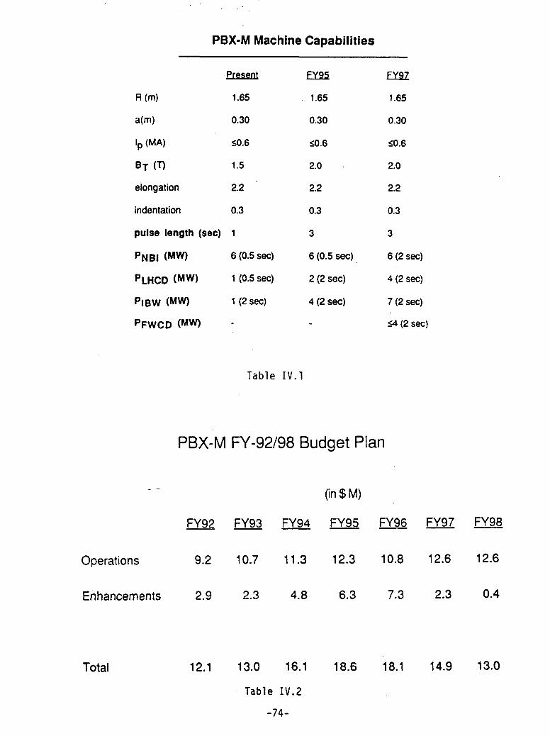
PBX-M Machine Capabilities
Present FY95 FY97
R (m) 1.65 1.65 1.65
a(m) 0.30 0.30 0.30
Ip (MA) <0.6 s0.6 <0.6
BT (T) 1.5 2.0 2.0
elongation 2.2 2.2 2.2
indentation 0.3 0.3 0.3
pulse length (sec) 1 3 3
PNBI (MW) 6 (0.5 sec) 6 (0.5 sec) 6 (2 sec)
PLHCD (MW) 1 (0.5 sec) 2 (2 sec) 4 (2 sec)
PIBW (MW) 1 (2 sec) 4 (2 sec) 7 (2 sec)
PFWCD (MW) - 4(2 sec)
Table IV.1
PBX-M FY-92/98 Budget Plan
(in $ M)
FY92 FY93 FY94 FY95 FY96 FY97 FY98
Operations 9.2 10.7 11.3 12.3 10.8 12.6 12.6
Enhancements 2.9 2.3 4.8 6.3 7.3 2.3 0.4
Total 12.1 13.0 16.1 18.6 18.1 14.9 13.0
Table IV.2
-74-

Exploration of the Physics in the High B and High Bp 2nd Stability Regime
I FY92 I FY93 FY 94 FY95 FY96 FY 9 r VOc
Demorion a ctrS SSAT Pralo-of High Sp HighB agra p" Isallatio I
Profile Con" t -Ujdn w O t
-current penetraroo-fast Oactron .Ol heun.s l Ca f em tu high e O
j(r) 0rspo sWITY trade on SC atWh lay
p(r) cnrlrI IBW.T.Q) heewtg p(O) ontrI fun.pircn oCD-.;A; --- I -aw T low T law High 80 and Hgh 9Ilr l.l l.. l be Y 1.M W Advanced regvne
shhpm9 U "am -diluI tal sh' a 0l Real-TirhaOncihage-Conlmcantral* fisthbone I internall kis
* newul nawovl sa. Vs shaps a QMPow.l enhacd HmodePatce a thI& ~nd
IMPUM~~~~~~~~~~~~~i·
ContrIo .. s 1.
PassiMmSub. vuvo dyjretPMrrltgIaerllodaclrve IDa~save shellSlab. "a Avooo~~~~~~~~0 iugio ~nanceLong pulse -now studies oOperabon raIon_________
Figure IV.3
Physics Studies Of Enhanced Confinement In PBX-M
ryw PY A I ry A I PY V FY CAI ry 07 I try CIA
I II oM BaBH Acv Shell SSAT Proto-Deronsran HihS High l High So Insaraiaon &IPyordeo onf Od t-~~lca1I Dwefor **or 9
Rdd Conl ' - Skin Uoorae
zdd coetm ,o MJ ilQ, LHCO
Uf lo8w on-&.* hab0 awllawiewr 'wo.'mmlb4 w transpor swam ba 6 ?i aspea seal
q(O) Conr ol mmdPO
p 0ii*, Un mU·Dp
bDtOrilal..) 2 ~cQO. bwo", ELMcnm
Q·"· ) CDR" m n Non 0 >Skin
S5usoihjp.gt High So H 8maM· nnl rtron I rd lumulem Advance eglrne
p~~ll·( UCD tmao cuff" _M lew Real-Tirne-Oiscnarge-Control
C..b.481.68 aw
CCSISSI@C 3) w 4W a
Itfb--~~~~~~ *H P·I.u0 F*WC- '~~~~~W~ -CI NuCOM
digital ""~~~~I >st'laft'",6, FWM I . MSM~lU FWW)
Comm Integraleo actwveioassve shellfor Csruotron Avo-ance
Figure IV.4
Disruption Avoidance in PBX-MI FY92 1FY93 FY94 1 FY95 1FY 96 FY97 FY98
~em~i~strationl Hqt B a c~,v Shen SSAT Proto-of High P High High Sp PSlii i
Profile Control -'sin
Passive *Stat)9ao. DV ors OM 10 .uwStabliinpg EL canrotlRire dew of 11195?SCe
Plasma ana0 VIWVng' syse K(o hlldischafaeControl neiurl )etSEE) tw .-0m cwwl
-ftax snapnq canlo Aeal-Tirne.scharge.Controi
Power. * a1er.*OSCiWe-CO Integrateactve I passwe $henilol p mPartice. -$ A" MR,* at
ImpqjntControl
Ovenor via enhanced denor aawnd l e e ,a d e lloo
t t t tv t law law2MW 2)4W 4 M
'MW
Fiaijr', TV r,
APPENDIX
UNIVERSITY OF CALIFORNIA, LOS ANGELES UCLA
BERKELEY · DAVIS * IRVINE LOS ANELES RIVERSIDE SAN DIEGCO SAN FRANCISCO SANTA BARBARA * SANTA CRUZ
ROBERT W. CONN OFFICE OFTHE DIRECTORDIRECTOR AND PROFESSOR INSTITUTE OF PLASMA AND FUSION RESEARCH
44-139 ENGINEERING iV405 HILGARD AVENUE
LOS ANGELES. CALIFORNIA 90024-1597
(213) 825-4544FAX: (213) 206-4832
Dr. David Baldwin, LLNL June 8, 1992Dr. Harold Weitzner, NYU
Dear David and Harold:
Thank you for agreeing to be chair and vice-chair of FEAC Panel 4 on "Priorities inthe Intermediate Confinement Experiments." Your report will provide important input tothe FEAC workshop in July on priorities in the overall fusion program. In addition, it willassist the FEAC in reaching its specific recommendation in September on the operation ofATF.
The facilities in the toroidal program that you are asked to evaluate and prioritize arethe ATF stellarator and the PBX, and C-Mod tokamaks. This should be done against thebackground of the DEI-D and TFTR capabilities, assuming that full D-T operation in TFTRbeginning in mid-1993 and a strong DIII-D program are supported as recommended in theApril 1 FEAC letter to Dr. Happer. As described below, I ask you to focus more on afactual evaluation for our July meeting, leaving for September a more completedetermination of a basis for FEAC recommendations on priorities.
For the July meeting, please provide the following information for each of theidentified mid-scale toroidal facilities:
1. The physics issues that are addressable in this class of facility and thecompleteness with which each of the identified devices can address these issues:and
2. For each device, the goals and objectives, additional hardware, the strengths,uniqueness, limitations, present status, projected costs and time required toachieve its objectives.
In addition, for the July meeting, please provide preliminary priorities and their time scalethat your Panel would assign to the operation of these facilities, along with an indication ofthe reasoning behind these priorities.
At the July meeting, the full FEAC will make use of your evaluations and your draftpriorities in its examination of the broader program. Later, in time for the Septembermeeting, I would like your panel to reexamine its preliminary priorities in light of theFEAC's July workshop and feedback provided there. Further, this will provide anopportunity for your Panel to hear responses from the programs reviewed. Your revisedpriorities will then serve as input to the September meeting of FEAC. This two-stepprocess will provide ample opportunity for each program to have a fair opportunity toanswer questions and concerns.
When this process has been completed, the FEAC must answer the followingquestions:
1. If the fusion budget is sufficient to do so, do all of the facilities warrantoperation? If not, which ones do not warrant operation?
2. If the fusion budget is not sufficient to operate simultaneously all the facilitieswhich warrant operation,
a) Should their operation be phased, implying one or more machines would bemothballed, and if so how?
b) Should all be operated at a reduced level? orc) Should one or more be closed down, and if so in what priority order?
The combination of your evaluations and priorities should be sufficient to permitFEAC to respond to Dr. Happer's request concerning the ATF and other priorities. Iunderstand that this will not be an easy undertaking for your Panel, for FEAC, or for theprograms involved since all are staffed by high quality groups. I will do all that I can toassist you in this endeavor.
Sincerely,
Robert W. Conn

Appendix II
Minutes of FEAC Meeting ofSeptember 22-23, 1992.

MINUTES
Meeting of Fusion Energy Advisory CommitteeRamada Renaissance Hotel13869-71 Park Center Road
Hendon, VA 22071
September 22 - 23,1992
Present: Dr. Robert W. Conn, Chairman, UCLADr. David E. Baldwin, LLNLDr. Klaus H. Berkner, LBLDr. Ronald C. Davidson, PPPLDr. Stephen O. Dean, Fusion Power AssociatesDr. Daniel A. Dreyfus, Gas Research InstituteDr. John P. Holdren, UCB
r Dr. Robert L. McCrory, Jr., University of RochesterDr. David O. Overskei, General AtomicsDr. Ronald R. Parker, MITDr. Barrett H. Ripin, NRLDr. Marshall N. Rosenbluth, UCSDDr. John Sheffield, ORNLDr. Richard E. Siemon, LANLDr. Peter Staudhammer, TRW, Inc.Dr. Harold Weitzner, NYU
Tuesday, September 22,1992 day, September 24,1992, which was the day immedi-ately following the projected cose of the current FEAC
Welcome and Opening Remarks meeting.
Dr. Conn called the meeting to order and welcomed Dr. Conn informed the meeting that two new chargethe committee members to the Ramada Renaissance letters had been received by FEAC. One concernedHotel at Herndon. He informed the committee that Dr. undertaking a review of the Inertial Fusion EnergyRichard E. Siemon's membership on FEAC, replacing (IFE) program, and the other asked for advice onDr. Rulon Linford, had recently been approved by the fusion-related materials and associated matters. Dr.Secretary of Energy. Dr Conn extended a warm wel- Conn indicated that several members of the public hadcome to Dr. Siemon on behalf of the committee. already made known their intentions to speak at the
meeting during the time set aside for public comment,Dr. Conn stated that the main purpose of the meeting and suggested that others who wished to speak shouldwas to work on, and finalize, the report that members contact the committee secretary.had been preparing following the one-week meetingof the Panel 5 ad hoc committee at Crested Butte, Up-Date from DOEColorado, where potential future strategies for the U.S.magnetic fusion program had been reviewed within Dr. N. Anne Davies announced that Dr. James F.the framework of a variety of budget scenarios. Dr. Decker was unable to attend the meeting and that heConn indicated that he had received a request from the sent his apologies to the committee. She stated that sheSecretaryof Energy Advisory Board (SEAB) to present would therefore make the entire presentation on be-to them FEAC's recommendations concerning the de- half of the Department of Energy, and that she wouldsign and construction of TPX, for each of the budget cover three major activities, viz. TFTR, ITER and TPX.scenarios that had been considered at Crested Butte.The meeting was scheduled for the morning of Thurs-
1

TFTR D-T Program #0). No decision had yet been made authorizing thestart of the conceptual design of TPX. The Secretary of
Dr. Davies began by summarizing the TFTR timetable; Energy, Admiral Watkins, had asked that a task forceshe indicated that the Office of Energy Research in- of SEAB review the matter before making a decision.tended using the TFTR D-T campaign as a test case The meeting was scheduled for September 24: FEACupon which to base the way in which all fusion-related had already heard that Dr. Conn would be addressingenergy research should be handled. Dr. Davies in- that meeting.formed thecommitteethatthePPPLOperational Readi-ness Review for the 1000 Ci Test was in progress. A Dr. Davies stated that the TPX National Council hadnine-member external review team had visitied PPPL been formed in August and had already made recom-and prepared a report on its findings. In turn, PPPL mendations to the Director of Princeton Plasma Phys-had developed an action plan aimed at implementing ics Laboratory concerning basic design parameterssuggested improvements. DOE's own Operational and the limit that should be placed upon total projectReadiness Review for the 1000 Ci Test, which would be cost. The selection of a Project Director for TPX was inconducted by an eleven-member team, was scheduled progress. Dr. Davies reported that the DOE had set afor January 1993. Tests of the tritium handling sys- cost limit for the construction of TPX of about $400tems, using small quantities of tritium, would begin million in FY92 dollars, expected to be equivalent toafter completion of the DOE Operational Readiness about $500 million in as-spent dollars. The DOE hadReview. All of the outstanding hardware required for also agreed that the project should start by focusingD-T operation is scheduled tobe installed by July 1993, upon the conceptual design of a 2.25m, 335T/1.87MAand both PPPL's and DOE's Operational Research steady-state advanced tokamak with superconduct-Reviews for full D-T operation were scheduled to be ing magnetic coils. Early objectives are aimed at com-completed by September 1993. The TFTR D-T pro- pleting a report on the conceptual design, togethergram is scheduled to start in September 1993, and to be with a detailed cost estimate, by March 1993. At thatcompleted by the end of September 1994. time it was intended that an international panel of
experts should conduct a thorough design review.ITER Activities
Dr. Davies pointed out that the language used in theDr. Davies reviewed the status of ITER The Interna- CongressionalAppropriationConferenceCommittee'stional Agreement to proceed with the Engineering budget supports undertaking TPX conceptual designDesign Activities had been signed, formally, on July activities in FY 1993. She provided the committee with21,1992. The first Council Meetinghadbeenheld early copies of the language: This is reproduced below.in September, when the nominations for Director andfor Deputy Directors had been approved. The struc-ture of the Joint Central Team had also been approved CONFERENCE COMMITTEE REPORTalong with the chairmanship and membership of the OF THE FISCAL YEAR 1993major working committees. Dr. Davies presented ENERGY AND WATER DEVELOPMENTviewgraphs that listed the key ITER personnel. APPROPRIATIONS BILL, H.R. 5373
The rules of procedure that ITER will use for conduct-SEPTMBER 15,1992ing business had been reviewed and approved. The MAGNE-nC FUSIONsize of the Joint Central Team had been discussed; thiscould number 150 personsby theend of Protocol I. The The conferees provide $339,710,000 forCouncil had requested that design and constructionfusion program. The confereesthe magnetic fusion program. The confereescost estimates be prepared by July 1993. The selection direct te Department of Energy to apply thisof theJoint Central Teamdivision directors was planed reduction in a manner that is cost effective andfor the end of September 1993, and the relocation of leastdisruptivethemissionandprioritiesleastdisruptive to the mission and prioritiesofJoint Central Team personnel was already underway. the magnetic fusion program.Dr. Paul Rebut, Director of ITER, had requested that amagnet testing facility be established. Since such a The conferees note with approval the re-facility had not previously been contemplated, theent agreement to proceed with the engineer-cent agreement to proceed with the engineer-matter was being investigated by a technical panel. ig d n a y p o ting design activity phase of the International
< TP;t fi fjw~~Thermonuclear Experimental Reactor (ITER).The conferees provide funds to meet fully theU.S. commitment to ITER and direct the De-Dr. Davies reported that an ESAAB meeting had beenStto dectthe D
*~., ' . . , ,,,„ , ~ .~ .~ *partment to provide a plan for selection of aheld in July to approve the mission need (Key Decision
2
U.S. candidate site for future construction of Foreaseof comprehension,Dr.Millerindicated thatheITER. had broken his task up into four main sections: the
purpose; the charter; the problem; and a proposal.The conferees recognize the technical "The purpose" was to focus attention on industrial
progress that has been achieved in magnetic involvement in fusion with a view to meeting thefusion energy here and abroad. The conferees objectives called out in FEAC's letter of February 14,direct the Department to assure that ITER, D- 1992 to DOE:T in TFTR, and the DIII-D program receive thehighest funding priority within the magnetic "The role of industry in the U.S. fusion pro-fusion program. The conferees have also pro- gram should be strengthened in order to pre-vided funds for design work leading to a pare industry for the major ITER-constructionsteady-state advanced tokamak planned for tasks. The international competition in ITERoperation as a national facility, will require the US. to develop a clear strategy
for U.S. industry involvement. Such a strategyThe FY 1993 Budget should take into account the different rela-
tionships between government and industryDr. Davies presented details of the initial budget pro- of the different ITER parties. As well, DOEposed by the Office of Fusion Energy for FY 1993 and procurement practices should be examined todrew comparison with anticipated final expenditures assure a leadership role for U.S. industry.forFY 1992. She pointed out that the FY 1993 numberswere still uncertain, for a number of reasons. First, the To provide U.S. industry with the knowledgetotal fusion energy budget that DOE had worked with of fusion requirements and to secure the maxi-for FY 1993 was $335 million; she explained that for mum benefit fromindustrial involvement, thereasonsof conservatism the lowerof theoriginal House DOE should develop a plan that deliberatelyand Senate mark-ups had been used. The conference includes a broader and more integral indus-committee had agreed upon the higher of the two trial participation in the fusion program. Thisfigures, viz. $339.7 million, and the budget spread now plan should encourage the development inneeded adjusting to reflect this. Second, a new expen- industry of both technical and programmaticditure category termed "General Reduction/Reserve" expertise and should allow for the continuityhad been established, which affected every division of this expertise over the long term."within the Office of Fusion Energy, and whichamounted to $10.6 million in the budget presented; Dr. Miller indicated that "the charter" had permittedthis reserve effectively reduced the funding available him to adoptaninformal approach to the study. Whileto programs by that amount. Dr. Davies explained that he had sampled, reviewed and evaluated the opinionsthe "General Reduction/Reserve" figures represented of very many experts, the conclusions contained in theestimates only and that since this was the first year of white paper were non-consensual; the views that weretheir inclusion, she did not know what the exact expressed represented one person's opinion, his own.amounts would be.
Turning to "the problem", Dr. Miller pointed out thatStatus of 1992 Reprogramming Request there was no government policy relating to industrial
involvement in fusion. Further, there was no signifi-Dr. Davies reviewed the status of the reprogramming cant investor-owned or public utility interest in therequest that had been made for FY 1992. Although the fusion program. He stressed that the fusion program'smajority of the reprogramming had been approved, potential customers were saying that they did not$7.6 million was still awaiting approval. Dr. Davies want the product. Worse, traditional vendors andfelt it was possible that this funding would yet be suppliers to fusion activities were losing interest. Dr.released. Miller emphasized that the fusion program would
have no future if it remained disconnected from itsIndustrial Participation in Fusion ultimate customers and its potential suppliers. He
stated that industry must "become" the program andDr. Bennett Miller presented a summary of his final indicated that now was the time for thefusionprogramreport concerning industrial involvement in the fusion to change from a scientific one to an industrial one.program. The report had been written as a "WhitePaper" in August, 1992 and was entitled "From Pa- Dr. Miller pointed out that significant changes in thetronage to Partnership - Toward a New Industrial way that utilities did business would take place overPolicy for the Fusion Program". the next ten years. Many cogeneration facilities were
being constructed and many small energy producers
3

would enter the marketplace. Dr. Miller felt these area. In the long term, it would ensure thatchanges may work to fusion's advantage. However, the persons who must ultimately carry thehe emphasized that the practices of the past must not technology into the commercial phase werebe repeated. Traditionally, when funding for fusion's the same ones who were planning its de-core program had increased, industry's interest and ployment.involvement in the program had increased. Con-versely, when the core programhad shrunk, industry's Dr. Conn reminded the committee that the vehicle thatinterest had waned. FEAC had suggested to DOE for bringing industry
back into fusion was ITER, via the U.S. Home Team'sDr. Miller explained the rationale for a new approach program. This would also prepare U.S. industry forto the fusion program. He stated that fusion was theconstructionphaseofITER. Dr. Millercommentedfeasible and emphasized that engineering, not science, that while this approach was good, it still left programwas the important next step. He pointed out that leadershipandcontrolinthehandsofgovernmentandindustry must be involved as a full-fledged partner for not with industry. Dr. McCrory stated that while hethis to succeed. felt that the partnership approach was good, he felt
that the timing was inappropriate: DEMO was too farDr. Miller reviewed the dominant traditional modes of into the future and commercial reactors were evengovernment-industry interaction. He explained that further away. Dr. Miller responded that such senti-he termed one mode the "vendor option"; this mode ments became self-fulfilling prophesies. He concededworked well when the government was purchasing that a time delay of 40 years to DEMO might present aexisting products, which implied that there was a problem but suggested that a delay of 20 years wouldsteady commercial market for them. Thesecondmode not. He pointed out that the actual timing wouldhe termed the "partnership option"; this mode worked depend almost entirely upon the level of effort thatwell when a research program was needed in order to was put into the program. He noted that another factordevelop the required product. The partnership option would soon come into play that might help matters:could be commercially-linked or not. In the commer- EPRI controls the energy market now, but it will not incially-linked version, the government procured novel 10 - 15 years' time.defense systems by having industry develop a productthat DOD laboratories tested, and that was then re- Dr. Siemon asked if, in Dr. Miller's scenario, it wasfined and retested in an iterative process, at goverment intended that universities and national laboratories beexpense, until a viable, economic product was devel- a part of the partnership. Dr. Miller responded affir-oped that balanced the demands of defense with the matively but added the qualification that he saw themrealities of commercial manufacturing practices. In being "little" partners. Dr. Siemon pointed out thatthe non-commercial version, the government recog- since the technology currently resided at the universi-nized that there would never be a ready market for the ties and national laboratories, they should play a largeend product of the needed development program and, role during the transition period. Dr. Miller agreedon a competitive basis, selected and made a long-term with this suggestion.commitment to an industrial partner to develop prod-ucts based upon a unique technology. Dr. Dreyfus emphasized that large construction com-
panies, large equipment vendors, and large utilitiesDr. Miller concluded by describing "a proposal". He must be involved in future fusion developments sincesuggested that DOE should develop a policy towards these were the entities that were going to construct,industry that embodied some form of non-commercial equip and operate the fusion facilities. He stressed thatpartnership option as the next step in the fusion pro- the new legislation relating to public utilities wouldgram. He stated that even though critics would object not result in the formation of a large number of "momto the proposal, a number of features commended it: and pop" energy generation concerns. Dr. Overskei
suggested that the committtee should clarify in their* It presented an accepted mode of govern- minds who or what the actual customer for their
ment-industry interaction, albeit not a very product was likely tobe. He emphasized that makingcommon one. the assumption that the utilities would be the cus-
* It addressed industry's two major concerns: tomer was incorrect. Rather it was the high-technol-a major role in program definition; and a ogy companies that would be the customers for fusionstable, predictable business environment, technology.
* It would benefit the taxpayer in both theshort and the long term. In the short term, it Dr. Baldwin returned to the question of timing, statingwould ensure that real corporate commit- that although components associated with the ITERments were made to fusion as a business project needed to be developed now, there would bea
4

long period between ITER and the next fusion ma- would be the wrong time to start a transfer program tochine. He questioned what would happen to the industry. Dr. Rosenbluth further stated that the ap-transfer program in the meantime and, worse, what proach suggested by FEAC, which would involvewould happen even earlier if ITER itself did not get using ITER as the transfer vehicle, was the correct waybuilt. He stated that if the commitment to transfer was to proceed at present.made at the wrong time, and if the U.S. fusion programwas unable to continue to supply support over a Dr. Staudhammer said that he wished to make a state-significant period of time, then the transfer program ment for the record. He stated that he wished towould fail. Dr. Miller agreed that starting the transfer compliment Dr. Miller fora very finepieceof work. Heprogram now involved risk, but it was his opinion that expressed concern that FEAC might leave the reportit was the right thing to do. unattended for a very long time. Dr. Staudhammer
pointed out that the work had raised many questionsDr. McCrory referred to his earlier question and stated to which no answers had been provided. He suggestedthat while he agreed that one could get industry in- that DOE generate a charge, possibly to FEAC, to lookvolved and interested in the fusion program by chang- into the matter and provide some answers. Dr. Conningtheanticipated time-scale,therewasfarmoretothe responded that Dr. Staudhammer's recommendationproblem than that. The industries that would be had been noted.involved in fusion were those that were involved infission. However, whereas the fission/fossil fuel trade- Dr. Dean pointed out that FEAC had made a recom-offs were well known, it was not even known whether mendation to DOE that DOE provide a policy concern-fusion would proceed to commercial reality. A gov- ing industrial involvement in the fusion program.eminent policy was needed that endorsed fusion as a DOE had acted upon that recommendation and hadfuture energy source. Dr. Overskei stressed that the asked Dr. Miller to evaluate the situation. In turn, Dr.issue of commitment was of paramount importance. Miller had provided a report on the matter. Dr. DeanThe national laboratories had carried forward a corn- stated that DOE now needed to take the input pro-mitment to fusion for years simply because they were vided by Dr. Miller and by FEAC and draft theirpaid to do so. Likewise, industry only does what it is industrial policy. Dr. Conn agreed and suggested thatpaid to do. Industry will not carry fusion forward DOE should come back to FEAC with its policy when-unless it is paid to do so. ever it was ready.
Dr. Conn stated that thereappeared tobegreat interest Dr. Sheffield endorsed Dr. Staudhammer's remarkon the part of FEAC in trying to move the program in that FEAC should not now discard Dr. Miller's reportthe direction that Dr. Miller had suggested but that and do nothing about it.committee members were concerned with minimizingthe risk involved and controlling it on the "down Report from Panel 4side". He reiterated that he saw the opportunity asrevolving around ITER. Dr. Staudhammer stressed Dr. Baldwin reviewed the activities of Panel 4. Hethat industry would not make a commitment to the reminded FEAC that Panel 4 had been asked to pro-program unless there were profits to be made. He vide input to Panel 5 at Crested Butte in July. Panel 4emphasized that commitments and large investments was therefore forced to respond very rapidly to itswere made not on feasibility but on perceived com- charge. Also, the charge given to Panel 5 overlappedmercial value. The stumbling block impeding to some extent that of Panel 4, and this overlap hadindustry's entry into the fusion program was that, in affected the manner in which Panel 4 had functioned.the present economic environment, some existing par-ticipating group would have to give something up. Dr. Baldwin reminded the meeting that the charge to
Panel 4 had been to evaluate and prioritize ATF, AlcatorDr. Parker stated that the question of identifying the C-Mod, and PBX-M. Later in the process the chargetrue customer for fusion was of vital importance and had been expanded to include the DIII-D upgrade.should not be overlooked. The possibility existed that The report that the panel had prepared containedthe fusion program could be aimed at satisfying the background information on the four facilities and in-wrong customer and in so doing end up with the cluded program plans and programmatic roles, facil-wrong product. Dr. Rosenbluth drew attention to the ity limitations, and projected costs. The panel'spriori-fact that, at ignition, alpha particle effects would be- ties had been presented at the FEAC workshop income pronounced and that the program was entirely Crested Butte as input to the strategic program plan-lacking in experience in this area. He added that work ning exercise.on low-activation materials had yet to show commer-cial feasibility. As a result, it was his opinion that now Dr. Baldwin stated that the problem that had emerged
5
for the panel when determining priorities, lay in the ment that everyone had worked on since the end of thefacts that all four facilities were staffed by excellent workshop. He pointed out that changes to the reportgroups of scientists, and all four programs were ad- would be made in "real time" and that it would bedressing vitally important programmatic issues. Dr. necessary to change the agenda in order to completeBaldwin reviewed, briefly, the major features of each the process before the meeting ended.facility and the tasks each was particularly suited toaddress. He stated that, as was customary with FEAC Review of Charge to FEACpanel reports, the recommendations of the panel hadnot been included in it: They had, instead, been Dr. Conn drew the committee's attention to the Letterprepared in viewgraph form for presentation at the of Charge of June 22,1992 and reviewed the reasonscurrent meeting. The viewgraph showed: why the letter had been written. He reminded the
committee that during the last twelve months they hadHigher Priorities reviewed several important elements of the fusion
ATF program but never the program as a whole. FEAC hadfelt that it needed to ensure that the sum of the "parts"
DIII-D Upgrade that it had proposed did not amount to more than thetotal program could afford, and so had suggested that
Lower Priorities DOE prepare a charge asking that FEAC undertake a
Alcator C-Mod review of the strategy underlying the entire magneticfusion program. Dr. Conn briefly reviewed the letter
PBX-M itself.
Dr. Baldwin explained that the panel had placed ATF Review of FEAC Program Strategy Reportin the higher priority category since it felt it wasimportant for the U.S. to maintain a sound position Dr. Conn explained the order in which he proposedinternationally in this technology. that FEAC should deal with the program strategy
report. He suggested that the committee deal with theDr. Conn pointed out that essentially the same data Executive Summary last. He indicated that Chapters 2had been presented to Panel 5 at Crested Butte. He and 3 should be discussed and finalized first, since thesuggested that FEAC accept the report and thanked material contained in these was essentially non-con-the panel for a job well done. Dr. Dean asked how troversial. This discussion should be followed by oneFEAC was intending to handle publication of this on Chapter 4, which related to program elements. Dr.report. He pointed out that until recently, UCLA had Conn stated that Dr. Weitzner had agreed to lead thebeen responsible for publishing them. Dr. Conn re- discussion on that chapter. Chapter 5, which con-plied that DOE had expressed a desire to publish the tained the committee's recommendations, should beFEAC reports themselves and in factItad already reviewed next; Dr. Conn said that Dr. Baldwin hadrepublished the first four as official DOE reports. Dr. agreed to lead that discussion. Finally, the discussionBaldwin suggested that FEAC forward the Panel 4 should return to the executive summary when everyreport to Dr. Happer with a simple letter of transmis- effort should be made to ensure that it was consistentsion explaining that it had been used as background with Chapter 5.for Panel 5.
Throughout the remainder of the day, the committeeDr. Anne Davies informed the committee that OFE reviewed as much of the report as time permitted.had prepared a document on TPX for presentation atthe SEAB Task Force meeting that was scheduled for Wednesday, September 23,1992the day following the end of this FEAC meeting. Cop-ies were made available to committee members. Dr. Review of FEAC Program Strategy ReportDavies stated that the other main topic for the SEABmeeting was the advanced neutron source (ANS). Throughout the majority of the morning session, the
committee continued to review the program strategy
Change of Agenda report but did not complete the task.
Dr. Conn stated that the outcome of Panel 5 would be Public Commenta FEAC report and not a Panel 5 report. He indicatedthat much of the balance of the present meeting would Dr. Bogdan C. Maglich, Advanced Physics Corporation,bedevoted toreviewingand modifyingthedraftdocu- presented a brief paper aimed at ways of broadening
support for fusion and significantly increasing OFE's
6

budget. He stated that the DOE's fusion program had or for breeding weapons fuel.no constituency among the nation's industrial, envi-ronmental or public interest groups that, logically, one * The non-proliferation lobby opposes fu-would expect to be supportive of environmentally sionbecauseanyD-Tfueled reactorcanbeattractive power technologies. He suggested that the used to breed plutonium and tritium.program should be modernized, broadened and in-creased through government-industry partnership Dr. Maglich stated that much of the opposition toprojects and through the incorporation of smaller de- fusion would dissipate if a study were initiated tovices into the program that would permit hundreds of develop an environmentally attractive fusion poweruniversities and R&D companies to undertake fusion reactor that wasbased upon theuseof non-radioactiveresearch. fuels. He suggested that a tokamak that used 3He-D as
the fuel would make a good starting point.He stated that his company had examined the under-lying causes behind the stagnation of the U.S fusion Dr. Maglich suggested that a study be undertakenprogram by canvassing the attitude toward fusion of regarding how to apply the time-sharing principlesall the special interest groups that would be expected agreed for the high-energy collider to the major toka-to support fusion research. They had reached the maks, thustoattractmanymoreuniversitiesand smallsurprising conclusion that, almost universally, such research groups into the fusion program. He alsogroups either were not supportive of fusion or were suggested that OFE hold a contest relating to newdirectly opposed to it. Dr. Maglich quoted the follow- concepts for compact, non-radioactive fueled fusioning examples: systems, and that DOE actively promote a govern-
ment-industry partnership program.* The energy independence movement is
indifferent to fusion because it believes Dr. Sheffield pointed out that perhaps more universi-that fusion will not replace oil. It esti- ties were involved in fusion than one might think. Hemates that oil consumption would be re- stated that 45 universities had participated in ORNLduced by only 5% through fusion. fusion projects in recent years. Dr. Conn agreed that
replacing oil with fusion in power generation would* The electric power industry has no inter- have little effect on overall oil consumption, but pointed
est in fusion since it believes that fusion's out that 70% of all oil was used in transportation. Ifuse of radioactive fuel will make it envi- transportation were to convert to electric tractionronmentally unacceptable. In addition, power, then the potential effect of fusion on oil con-the industy believes that fusion will be sumption would be much greater. Dr. Maglich ac-excessively capital intensive and unlikely cepted this point but emphasized that it might be coal,to be economically viable, and not fusion, that would benefit from this change.
He stressed that the coal industry and its allies com-* The electric power equipment industry prised the main anti-fusion lobby.
considers fusion unacceptable simply be-cause it is a "nuclear" technology. Cur- Review of FEAC Program Strategy Reportrently envisioned fusion power plantswould replacecoal-fired plantswhich pro- During the early part of the afternoon session, thevide about 50% of today's power generat- committee continued with its review of the programing capacity. The powerful coal lobby is strategy report until ithad completed Chapter5. It wasintent on stopping fusion. agreed that the report would be modified to reflect the
changes that the committee had agreed upon and sent* The university community is opposed to to members for final review before it was forwarded to
the present approach of constructing the Director of Energy Research.multi-billion dollar devices since thispolicy effectively excludes all but a few New Charges to FEACfrom participation in fusion research.
Dr. Conn informed the committee that FEAC had* The responsible environmental move- received two new charges from Dr. Happer. He pro-
ment, centered around the Union of Con- posed to establish two new panels, Panel 6 and Panelcerned Scientists, opposes fusion because 7, to review these charges and to provide input toit is "nuclear" and there is no exclusively FEAC. The first charge, which would be reviewed bypeaceful nuclear energy: Any nuclear Panel 6 and for which a response was requested byreactor can be converted for weapons use February 1993, concerned the Neutron Intereactive
7
Materials Program of the Office of Fusion Energy. The Dr. Stephen Deansecond, which would be reviewed by Panel 7 and had Dr. Ronald Davidsona requested response date of April 1993, concerned the Dr. Barrett RipinInertial Fusion Energy Program of Energy Research. Dr. David BaldwinDr. Conn added that he would like both panels to Dr. John Sheffieldprovide FEAC with an interim report on progress at Dr. Robert McCrorytheir next meeting and suggested that a date inJanuary Dr. David Overskeimight be suitable.
The committee agreed that Dr. Conn should work withAfter some discussion, FEAC agreed that a better whomever was chosen as chairman to select and inviteresponse to the charge concerning the materials pro- to join this panel appropriate scientific experts thatgram would result if it could be delayed until March would include representatives of the inertial fusion1993, provided that this delay would be acceptable to community.DOE.
Dr. Conn led a discussion concerning possible mem-bership of the two panels and the availability of mem- Terrence A. Daviesbers of FEAC to serve on them. IPFR/UCLA
October 12,1992Establishment of Panel 6
Dr. Conn suggested that Dr. Berkner be the chairmanof Panel 6, which would review materials matters.Members of FEAC who will sit on Panel 6 were agreedas follows:
Dr. Klaus Berkner, ChairmanDr. Richard SiemonDr. Stephen DeanDr. Harold WeitznerDr. Marshall RosenbluthDr. John HoldrenDr. Peter Staudhammer
The committee agreed that Dr. Berkner should workwith Dr. Conn to select and invite appropriate scien-tific experts to join the panel and expand its range ofexpertise.
Establishment of Panel 7
Before selection of the membership of this panel, adiscussion took place on the breadth of the charge. Dr.Staudhammer pointed out that the panel might expe-rience difficulty regarding access to classified mate-rial. The selection of the chairman was also reviewed,bearing in mind that conflict-of-interest issues involv-ing the apportionment of funding between the mag-netic and inertial fusion programs needed to be seen tobe avoided. It was agreed that the matter of thechairman for this panel would be discussed with theinertial fusion program directors before any decisionwas made. The members of FEAC who will sit onPanel 7 were agreed as follows:
8