fundamental aeronautics program - nasa · fundamental aeronautics program ... w/ wet clutchdouble...
TRANSCRIPT

National Aeronautics and Space Administration
Fundamental Aeronautics ProgramSubsonic Rotary Wing Project
V i bl S d R t ft D i S t R h
Dr. David G. LewickiResearch Mechanical EngineerRXN/Tribology & Mechanical Components Branch, Glenn Research Center
Variable-Speed Rotorcraft Drive System Research
Mark Stevens, Mechanical & Rotating Systems Branch, Glenn Research CenterHans DeSmidt, Associate Professor, University of Tennessee
2012 T h i l C f
1www.nasa.gov
2012 Technical ConferenceMarch 13-15, 2012
https://ntrs.nasa.gov/search.jsp?R=20150010357 2018-07-06T12:58:22+00:00Z

Background
High speed
Variable-speedVariable-speedpropulsion (50%)
References:References:• Johnson, W., Yamauchi, G.K., and Watts, M.E.,
"NASA Heavy Lift Rotorcraft Systems Investigation", NASA/TP-2005-213467, Rept-A-0514419, December 2005.
• Acree, C.W., Hyeonsoo, Y., and Sinsay, J. D.,
Applications:Applications:• Large civil tilt rotor• Joint heavy lift
22
“Performance Optimization of the NASA Large Civil Tiltrotor” International Powered Lift Conference, London, UK, July 22-24, 2008.
• Unmanned air vehicle

Objective
Develop variable-speed drive
t t h l i f t ftsystem technologies for rotorcraft
applications to allow 50% speed
change of rotors with minimal
impact on weightimpact on weight.
33

State-of-the-Art
• Most current rotorcraft operate at fixed speed.p p• V22: 15% speed change, slowing down engine.• A160 Hummingbird: two-speed transmission,
relatively heavy.• Automotive: heavy, not enough power capacity.
• Innovative speed change technology requiredInnovative speed change technology required, continued drive system weight reduction required.
44

Approach
• Development of variable-speed transmission test facility (in-house).
• Development of variable-speed transmission concepts (in-house, industry).
D i d li f i bl d d i• Dynamic modeling of variable-speed drive systems (NASA NRA, Penn St, Univ. of Tennessee).)
55

• Development of variable-speed transmission test facility (in-house).
• Development of variable-speed transmission concepts (in-house, industry).
D i d li f i bl d d i• Dynamic modeling of variable-speed drive systems (NASA NRA, Penn St, Univ. of Tennessee).)
66

GRC Variable-Speed Transmission Test Facility• Dual-motor (driver & loader) facility configuration: allows versatility in allowable
designs available to test.• 15000 rpm input speed, 7500-15000 rpm output speed (0-50% reduction ratio).
M t 140 ft lb f 0 7500 200 h f 7500 15000• Motor power: 140 ft-lb from 0-7500 rpm, 200-hp from 7500-15000 rpm.• Power regenerative motor configuration.• State-of-the-art motor controllers & PLC's.• Allows scripted speed, torque, & clutch loading profiles.p p q g p
77

GRC Variable-Speed Transmission Test Facility
88

Facility Validation Tests Completed
• Successfully operated at fulloperated at full speed & torque.
• Successfully demonstrated prescribed speed & torque control.
99
GRC Variable-Speed TransmissionTest Facility
Facility Check-Out Test Results
Milestone: (SRW.01.01.108) Complete Fabrication, Assembly, and Check-Out of Variable-Speed Test Facility: 2-23-12

• Development of variable-speed transmission test facility (in-house).
• Development of variable-speed transmission concepts (in-house, industry).
D i d li f i bl d d i• Dynamic modeling of variable-speed drive systems (NASA NRA, Penn St, Univ. of Tennessee).)
1010

Configurations To Test
1) Offset Compound Gear Drive w/ Dry Clutch.
2) Offset Compound Gear Drive w/ Wet Clutch.
3) Double Star Idler Planetary w/ Dry Clutch.
4) Double Star Idler Planetary w/ Wet Clutch4) Double Star Idler Planetary w/ Wet Clutch.
1 Stevens, M.A., Handschuh, R.F., and Lewicki, D.G., "Concepts for Variable/Multi-Speed Rotorcraft Drive System", Proceedings of the 64th American Helicopter Society International Forum, Montreal, Canada, April-May 2008 (also NASA TM-2008-215276, Army Research Laboratory Report ARL-TR-4564, AHS Paper No. 080273).2
1111
2 Stevens, M.A., Handschuh, R.F., and Lewicki, D.G., "Variable/Multispeed Rotorcraft Drive System Concepts", NASA TM-2009-215456, Army Research Laboratory Report ARL-TR-4758, March 2009.

Offset Compound Gear Drive
Output gear
Gear cluster
Input gear
1212
"Offset Compound Gear Inline Two-Speed Drive", U.S. Patent No. US 8,091,445 B1, Jan 10, 2012.

Offset Compound Gear Drive w/ Dry Clutch
Offset compound gear drive
Dry clutchSupport bearing
Support bearing
Lubedistribution
bearing
Input Output
1313Fixed stations
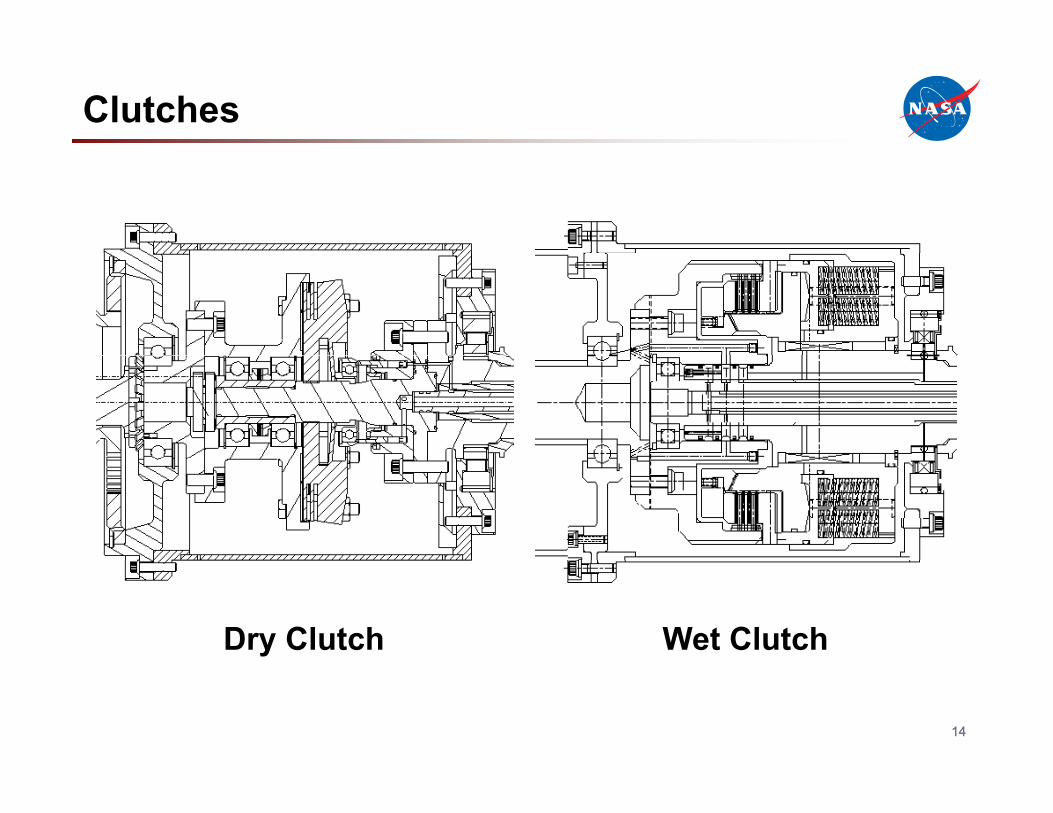
Clutches
Dry Clutch Wet Clutch
1414

Double Star Idler Planetary
Planet star gearPlanet idler gear
Input gear
Ring gear
1515

• Development of variable-speed transmission test facility (in-house).
• Development of variable-speed transmission concepts (in-house, industry).
D i d li f i bl d d i• Dynamic modeling of variable-speed drive systems (NASA NRA, Penn St, Univ. of Tennessee).)
1616

Drive System Dynamic Modeling
1717

Two-Speed Tiltrotor Driveline
Left Nacelle(Twin Two Spool Gas
Turbine Engines)Initial
Ratio, ni
Dual Clutch TransmissionnDCT,low &nDCT,high Final
Ratio, nf
Left RotorLeft Nacelle(Twin Two Spool Gas
Turbine Engines)Initial
Ratio, ni
Dual Clutch TransmissionnDCT,low &nDCT,high Final
Ratio, nf
Left Rotor
NASA LCTR-2NASA LCTR-2
FWU
FWU1:1
FWU
FWU1:1
FWU
Cross-Shaft
ForwardSpeed
Blade Pitch
Clutch Engagement
Pressure Inputs
Multi-EngineFuel Control
FWU
Cross-Shaft
ForwardSpeed
Blade Pitch
Clutch Engagement
Pressure Inputs
Multi-EngineFuel Control
FWU
Blade PitchControl
Pressure Inputs
FWU
Blade PitchControl
Pressure Inputs
• DCTs upstream from cross-shaft
FWU
Right Nacelle InitialFinal
Ratio n
1:1
Dual Clutch
FWU
Right Nacelle InitialFinal
Ratio n
1:1
Dual Clutch
• Maintains rotor indexing phase
1818
Right Nacelle(Twin Two Spool Gas
Turbine Engines)
Initial Ratio, ni
Ratio, nf
Right Rotor
TransmissionnDCT,low &nDCT,high
Right Nacelle(Twin Two Spool Gas
Turbine Engines)
Initial Ratio, ni
Ratio, nf
Right Rotor
TransmissionnDCT,low &nDCT,high

Comprehensive Propulsion System Model
1919

Sequential Shift Control – Downshift
SSC Downshift Sequence:FWU
F l
SSC Downshift Sequence:1. Disable GTE torque sharing
control loop2. Left side DCT downshift3 Ri ht id GTE d Fuel
Control3. Right side GTE ramp-down4. Right side DCT downshift5. Right side GTE ramp-up6. Re-enable GTE torque
Fuel Control
qsharing control loop
Advantages: FWUFWUFWUAdvantages:• Always under engine
power• Avoids clutch engagements
2020
Reference: Litt, J.S., Edwards, J.M., and DeCastro, J.A., “A Sequential Shifting Algorithm for Variable Rotor Speed Control,” NASA/TM 2007-214842 (2007).
g gunder full power

Downshift Example Results
Set point
ActualActual
Right rotorLeft rotor
High speed clutch
Low speed clutch
Low speed clutchHigh speed clutch
2121
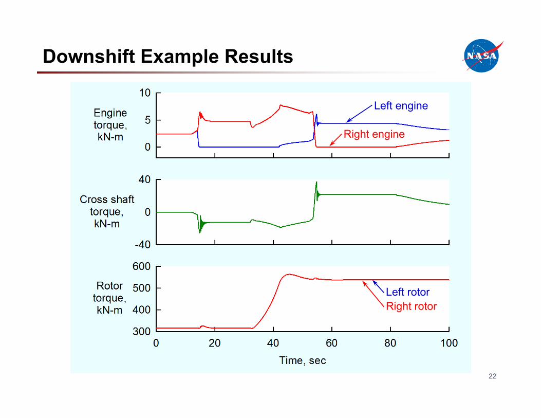
Downshift Example Results
Ri h i
Left engine
Right engine
L ft tRight rotorLeft rotor
2222

23Your Title Here 23