functions of the sfc -vtec - complete · pdf filefunctions of the sfc -vtec ... • if...
TRANSCRIPT
Downloaded from
Page 1 of 1
Functions of the SFC-VTEC
SFC Functions
• Compatible with stock & modified ECU's, and can modify fuel mapping for 8 RPM settings (1000, 2000, 3000, 4000, 5000, 6000, 7000, 8000), and can change the fuel delivery up to +/- 30%, in 1% increments.
• In "Realtime mode," the fuel delivery can be monitored in 100 RPM increments.
• When maximum fuel mapping of the SFC is reached, a (OF) display will appear.
• Can modify fuel settings on the fly, during constant RPM instances.
VTEC Functions
• Can modify the VTEC and/or MIVEC's hi-cam changeover point in 100 RPM intervals. (minimum 2000 RPM)
• When changing over to hi-cam mode, the "HI-CAM" indicator changes from green to red.
• Can modify hi-cam changeover settings on the fly, during constant RPM instances.
Other
• Speed limiter removal (certain models excepted) • Speedometer displays up to 999km. ("Speedometer mode") • Digital tachometer. ("VTEC mode") • For racing on the circuit, there is also a buzzer that can be set to shift points or
your redline. • If there is no input for 5 seconds during "Setting mode," it will automatically
return to "Realtime Mode." • Custom wire-harness couplers are sold seperately for users who do not want to
splice the stock wires.
Downloaded from
Page 2 of 2
SFC-VTEC Compatibility List & Wiring Diagrams
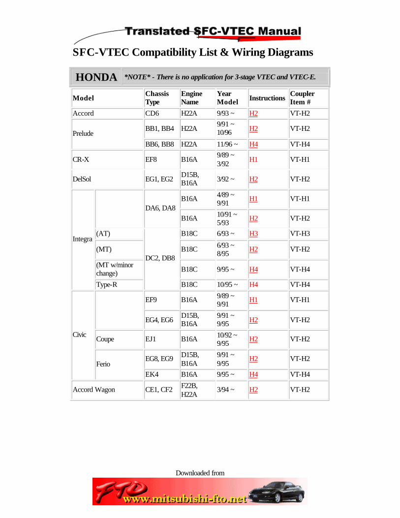
HONDA *NOTE* - There is no application for 3-stage VTEC and VTEC-E.
Model Chassis Type
Engine Name
Year Model Instructions
Coupler Item #
Accord CD6 H22A 9/93 ~ H2 VT-H2
BB1, BB4 H22A 9/91 ~ 10/96 H2 VT-H2
Prelude
BB6, BB8 H22A 11/96 ~ H4 VT-H4
CR-X EF8 B16A 9/89 ~ 3/92
H1 VT-H1
DelSol EG1, EG2 D15B, B16A 3/92 ~ H2 VT-H2
B16A 4/89 ~ 9/91
H1 VT-H1 DA6, DA8
B16A 10/91 ~ 5/93
H2 VT-H2
(AT) B18C 6/93 ~ H3 VT-H3
(MT) B18C 6/93 ~ 8/95
H2 VT-H2
(MT w/minor change) B18C 9/95 ~ H4 VT-H4
Integra
Type-R
DC2, DB8
B18C 10/95 ~ H4 VT-H4
EF9 B16A 9/89 ~ 9/91
H1 VT-H1
EG4, EG6 D15B, B16A
9/91 ~ 9/95 H2 VT-H2
Coupe EJ1 B16A 10/92 ~ 9/95
H2 VT-H2
EG8, EG9 D15B, B16A
9/91 ~ 9/95
H2 VT-H2
Civic
Ferio EK4 B16A 9/95 ~ H4 VT-H4
Accord Wagon CE1, CF2 F22B, H22A
3/94 ~ H2 VT-H2
Downloaded from
Page 3 of 3
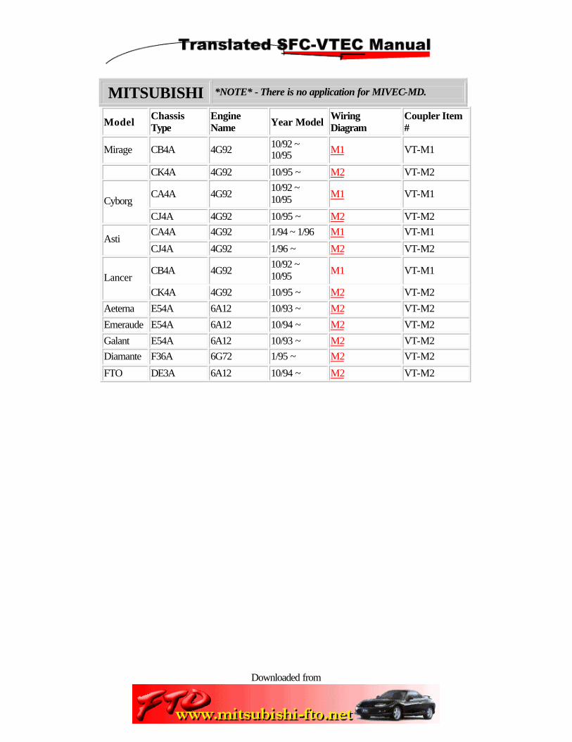
MITSUBISHI *NOTE* - There is no application for MIVEC-MD.
Model Chassis Type
Engine Name Year Model
Wiring Diagram
Coupler Item #
Mirage CB4A 4G92 10/92 ~ 10/95 M1 VT-M1
CK4A 4G92 10/95 ~ M2 VT-M2
CA4A 4G92 10/92 ~ 10/95 M1 VT-M1
Cyborg
CJ4A 4G92 10/95 ~ M2 VT-M2
CA4A 4G92 1/94 ~ 1/96 M1 VT-M1 Asti
CJ4A 4G92 1/96 ~ M2 VT-M2
CB4A 4G92 10/92 ~ 10/95 M1 VT-M1
Lancer CK4A 4G92 10/95 ~ M2 VT-M2
Aeterna E54A 6A12 10/93 ~ M2 VT-M2
Emeraude E54A 6A12 10/94 ~ M2 VT-M2
Galant E54A 6A12 10/93 ~ M2 VT-M2
Diamante F36A 6G72 1/95 ~ M2 VT-M2
FTO DE3A 6A12 10/94 ~ M2 VT-M2
Downloaded from
Page 4 of 4
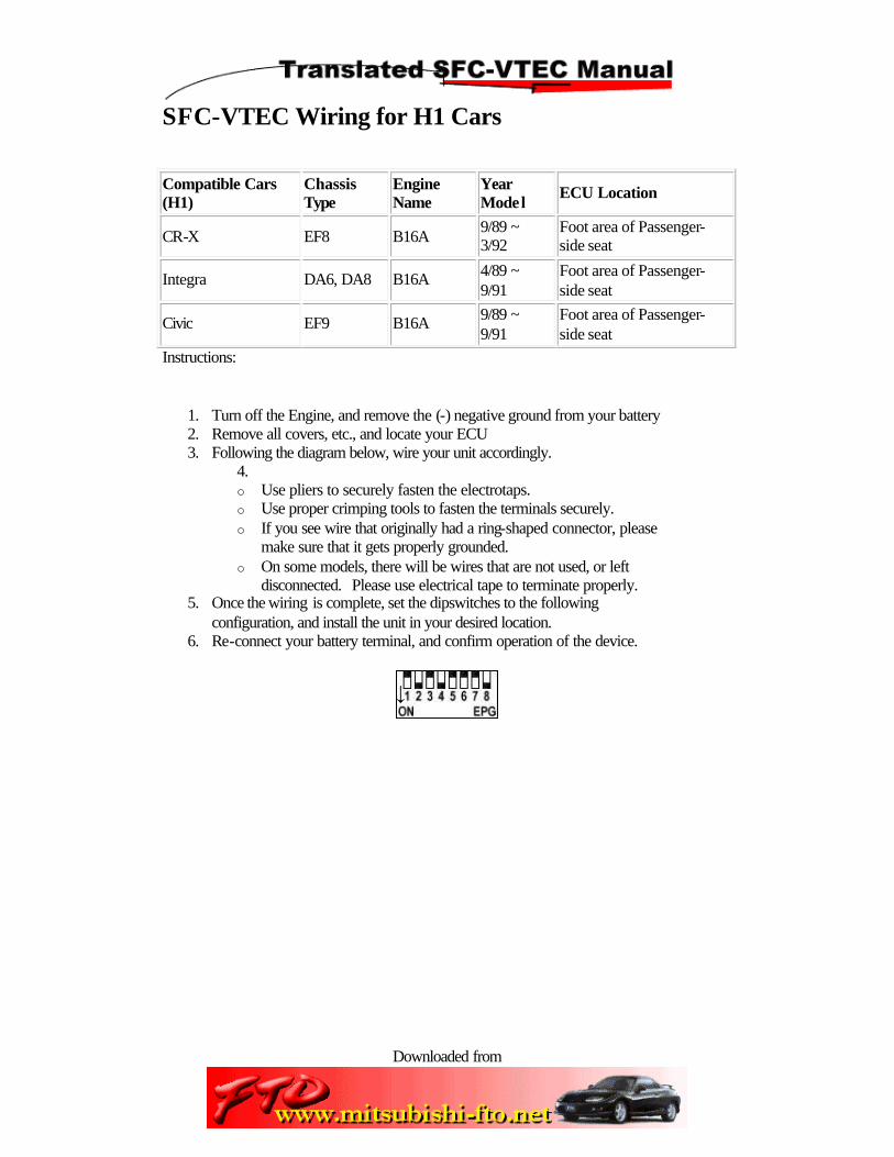
SFC-VTEC Wiring for H1 Cars
Compatible Cars (H1)
Chassis Type
Engine Name
Year Model
ECU Location
CR-X EF8 B16A 9/89 ~ 3/92
Foot area of Passenger-side seat
Integra DA6, DA8 B16A 4/89 ~ 9/91
Foot area of Passenger-side seat
Civic EF9 B16A 9/89 ~ 9/91
Foot area of Passenger-side seat
Instructions:
1. Turn off the Engine, and remove the (-) negative ground from your battery 2. Remove all covers, etc., and locate your ECU 3. Following the diagram below, wire your unit accordingly.
4. o Use pliers to securely fasten the electrotaps. o Use proper crimping tools to fasten the terminals securely. o If you see wire that originally had a ring-shaped connector, please
make sure that it gets properly grounded. o On some models, there will be wires that are not used, or left
disconnected. Please use electrical tape to terminate properly. 5. Once the wiring is complete, set the dipswitches to the following
configuration, and install the unit in your desired location. 6. Re-connect your battery terminal, and confirm operation of the device.

Downloaded from
Page 5 of 5

Downloaded from
Page 6 of 6
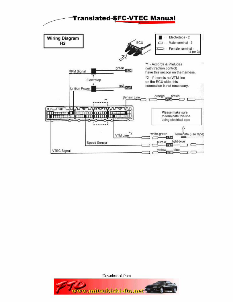
SFC-VTEC Wiring for H2 Cars
Compatible Cars (H2)
Chassis Type
Engine Model
Year Model
ECU Location
Accord CD6 H22A 9/93 ~ Foot area of Passenger-side seat
Prelude BB1, BB4 H22A 9/91 ~ 10/96
Foot area of Passenger-side seat
DelSol EG1, EG2 D15B, B16A
3/92 ~ Left foot area of Passenger-side seat
Integra DA6, DA8 B16A 10/91 ~ 5/93
Foot area of Passenger-side seat
Integra (MT) DC2, DB8 B18C 6/93 ~ 8/95
Left foot area of Passenger-side seat
Civic EG4, EG6 D15B, B16A
9/91 ~ 9/95
Left foot area of Passenger-side seat
Civic Ferio EG8, EG9 D15B, B16A
9/91 ~ 9/95
Left foot area of Passenger-side seat
Civic Coupe EJ1 B16A 10/92 ~ 9/95
Left foot area of Passenger-side seat
Accord Wagon CE1, CF2 F22B, H22A
3/94 ~ Foot area of Passenger-side seat
Instructions:
1. Turn off the Engine, and remove the (-) negative ground from your battery 2. Remove all covers, etc., and locate your ECU 3. Following the diagram below, wire your unit accordingly.
4. o Use pliers to securely fasten the electrotaps. o Use proper crimping tools to fasten the terminals securely. o If you see wire that originally had a ring-shaped connector, please
make sure that it gets properly grounded. o On some models, there will be wires that are not used, or left
disconnected. Please use electrical tape to terminate properly. 5. Once the wiring is complete, set the dipswitches to the following
configuration, and install the unit in your desired location. 6. Re-connect your battery terminal, and confirm operation of the device.
Downloaded from
Page 7 of 7

Downloaded from
Page 8 of 8
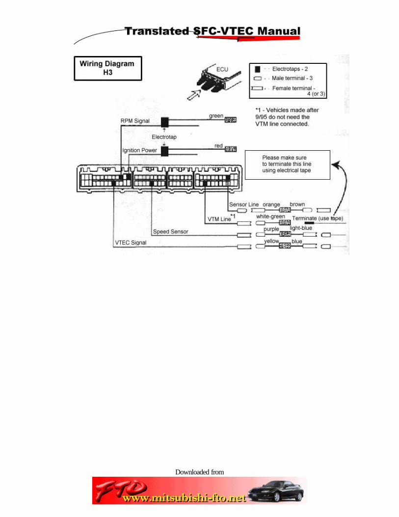
SFC-VTEC Wiring for H3 Cars
Compatible Cars (H3)
Chassis Type
Engine Name
Year Model
ECU Location
Integra (AT) DC2, DB8 B18C 6/93 ~ Left foot area of Passenger-side seat
Instructions:
1. Turn off the Engine, and remove the (-) negative ground from your battery 2. Remove all covers, etc., and locate your ECU 3. Following the diagram below, wire your unit accordingly.
4. o Use pliers to securely fasten the electrotaps. o Use proper crimping tools to fasten the terminals securely. o If you see wire that originally had a ring-shaped connector, please
make sure that it gets properly grounded. o On some models, there will be wires that are not used, or left
disconnected. Please use electrical tape to terminate properly. 5. Once the wiring is complete, set the dipswitches to the following
configuration, and install the unit in your desired location. 6. Re-connect your battery terminal, and confirm operation of the device.
Downloaded from
Page 9 of 9

Downloaded from
Page 10 of 10
SFC-VTEC Wiring for H4 Cars
Compatible Cars (H4)
Chassis Type
Engine Name
Year Model
ECU Location
Prelude BB6, BB8 H22A 11/96 ~ Foot area of Passenger-side seat
Integra (MT w/minor change) B18C 9/95 ~ Left foot area of
Passenger-side seat
Integra Type-R DC2, DB8
B18C 10/95 ~ Left foot area of Passenger-side seat
Civic EK4 B16A 9/95 ~ Left foot area of Passenger-side seat
Civic Ferio EK4 B16A 9/95~ Left foot area of Passenger-side seat
Instructions:
1. Turn off the Engine, and remove the (-) negative ground from your battery 2. Remove all covers, etc., and locate your ECU 3. Following the diagram below, wire your unit accordingly.
4. o Use pliers to securely fasten the electrotaps. o Use proper crimping tools to fasten the terminals securely. o If you see wire that originally had a ring-shaped connector, please
make sure that it gets properly grounded. o On some models, there will be wires that are not used, or left
disconnected. Please use electrical tape to terminate properly. 5. Once the wiring is complete, set the dipswitches to the following
configuration, and install the unit in your desired location. 6. Re-connect your battery terminal, and confirm operation of the device.

Downloaded from
Page 11 of 11
Downloaded from
Page 12 of 12
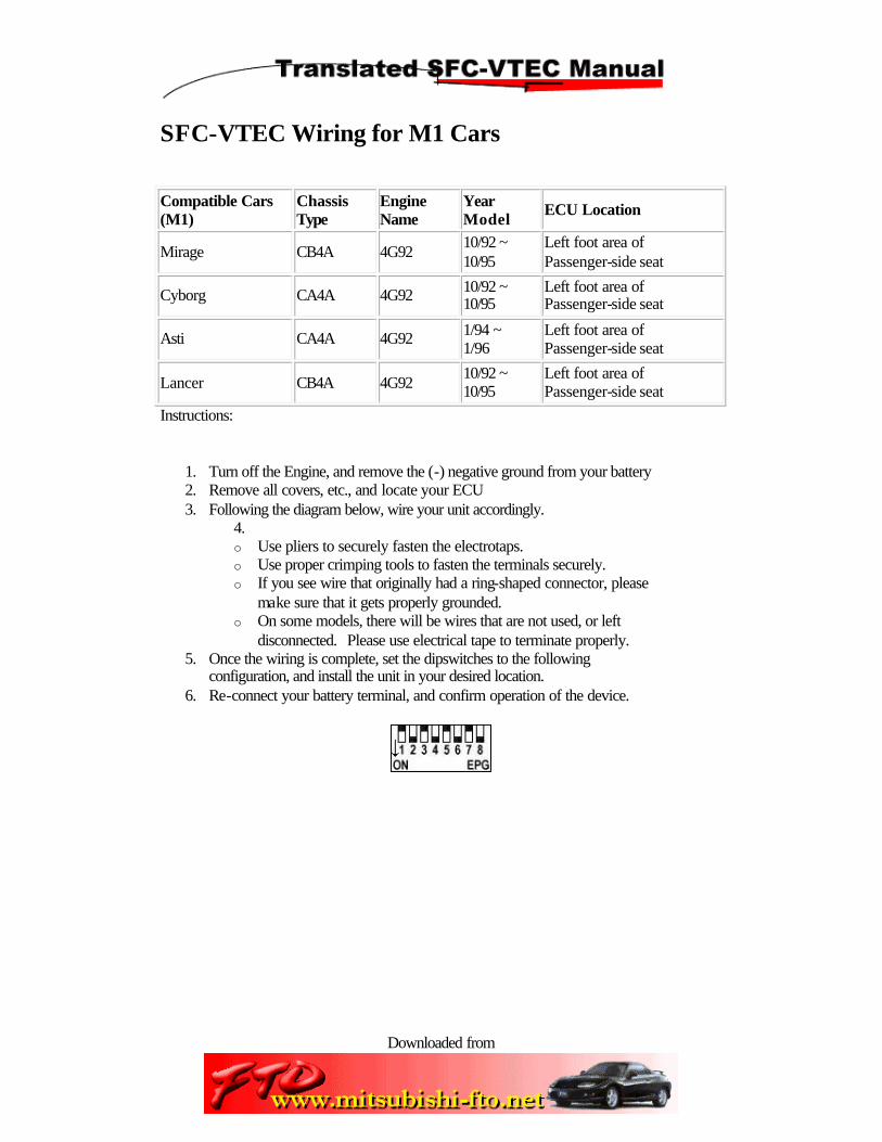
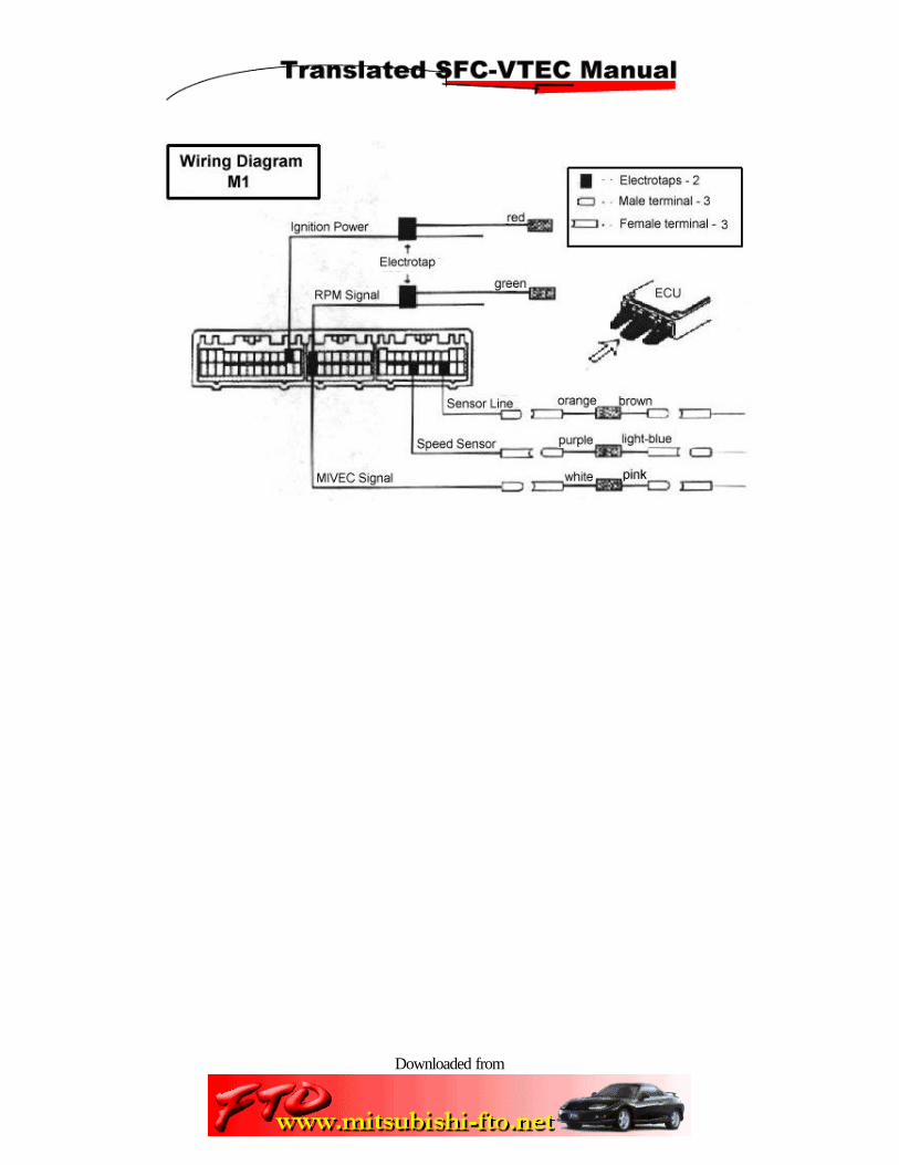
SFC-VTEC Wiring for M1 Cars
Compatible Cars (M1)
Chassis Type
Engine Name
Year Model
ECU Location
Mirage CB4A 4G92 10/92 ~ 10/95
Left foot area of Passenger-side seat
Cyborg CA4A 4G92 10/92 ~ 10/95
Left foot area of Passenger-side seat
Asti CA4A 4G92 1/94 ~ 1/96
Left foot area of Passenger-side seat
Lancer CB4A 4G92 10/92 ~ 10/95
Left foot area of Passenger-side seat
Instructions:
1. Turn off the Engine, and remove the (-) negative ground from your battery 2. Remove all covers, etc., and locate your ECU 3. Following the diagram below, wire your unit accordingly.
4. o Use pliers to securely fasten the electrotaps. o Use proper crimping tools to fasten the terminals securely. o If you see wire that originally had a ring-shaped connector, please
make sure that it gets properly grounded. o On some models, there will be wires that are not used, or left
disconnected. Please use electrical tape to terminate properly. 5. Once the wiring is complete, set the dipswitches to the following
configuration, and install the unit in your desired location. 6. Re-connect your battery terminal, and confirm operation of the device.
Downloaded from
Page 13 of 13
Downloaded from
Page 14 of 14
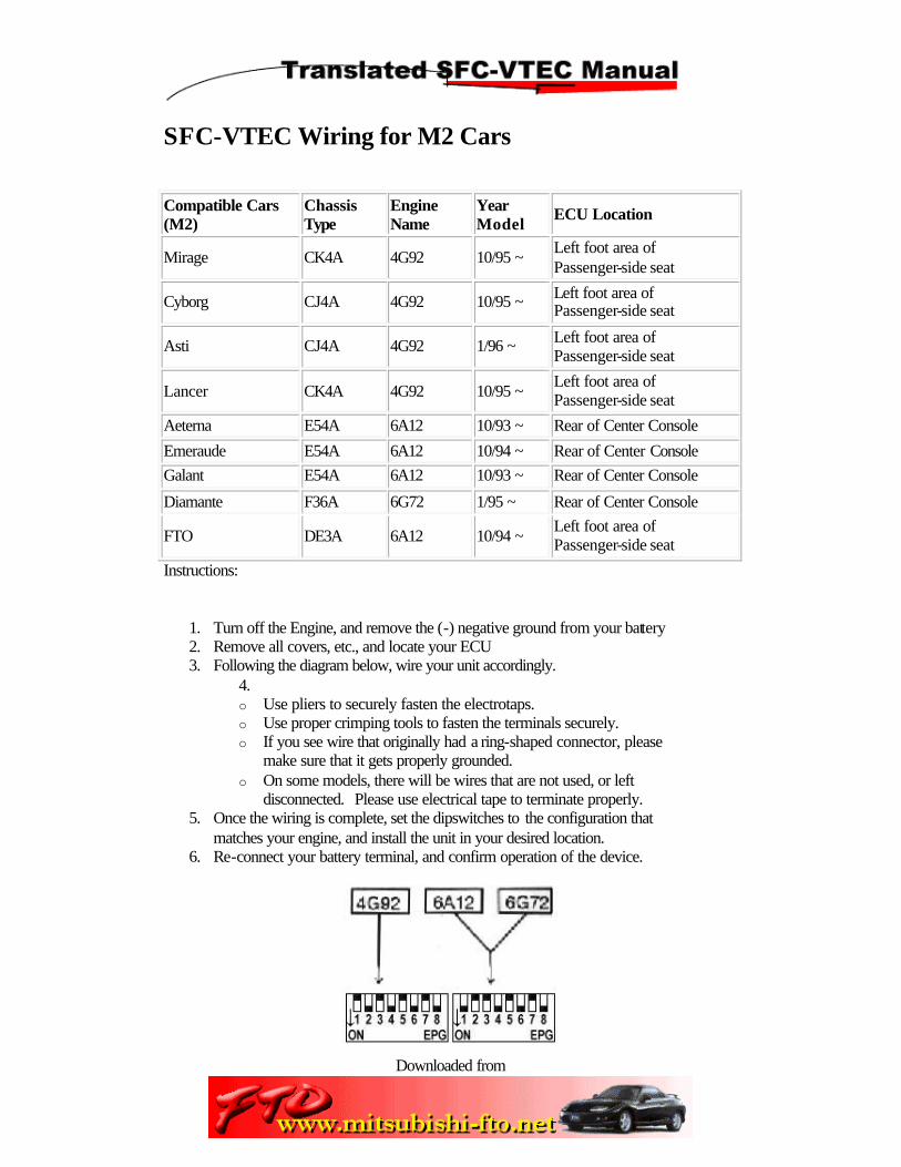
SFC-VTEC Wiring for M2 Cars
Compatible Cars (M2)
Chassis Type
Engine Name
Year Model
ECU Location
Mirage CK4A 4G92 10/95 ~ Left foot area of Passenger-side seat
Cyborg CJ4A 4G92 10/95 ~ Left foot area of Passenger-side seat
Asti CJ4A 4G92 1/96 ~ Left foot area of Passenger-side seat
Lancer CK4A 4G92 10/95 ~ Left foot area of Passenger-side seat
Aeterna E54A 6A12 10/93 ~ Rear of Center Console
Emeraude E54A 6A12 10/94 ~ Rear of Center Console
Galant E54A 6A12 10/93 ~ Rear of Center Console
Diamante F36A 6G72 1/95 ~ Rear of Center Console
FTO DE3A 6A12 10/94 ~ Left foot area of Passenger-side seat
Instructions:
1. Turn off the Engine, and remove the (-) negative ground from your battery 2. Remove all covers, etc., and locate your ECU 3. Following the diagram below, wire your unit accordingly.
4. o Use pliers to securely fasten the electrotaps. o Use proper crimping tools to fasten the terminals securely. o If you see wire that originally had a ring-shaped connector, please
make sure that it gets properly grounded. o On some models, there will be wires that are not used, or left
disconnected. Please use electrical tape to terminate properly. 5. Once the wiring is complete, set the dipswitches to the configuration that
matches your engine, and install the unit in your desired location. 6. Re-connect your battery terminal, and confirm operation of the device.

Downloaded from
Page 15 of 15

Downloaded from
Page 16 of 16
Basic Introduction to the SFC-VTEC
1) Mode Switch
Depending on how long you depress this switch, you can change the display information, or change modes.
Switch Definitions
Short Hold - ( < 0.5 seconds ) Long Hold - ( 0.5 ~ 2.0 seconds ) Continued Hold- ( > 2.0 seconds )
"Realtime Mode" (MODE switch lights up green)
Short Hold - (Switch to "Setting Mode") Long Hold - (Change functions within "Realtime Mode") Continued Hold - (Returns to normal)
"Setting Mode" (MODE switch lights up green)
Used only to adjust SFC Functions, the MODE switch will move your fuel mapping to the next RPM level. After adjusting the 8000RPM mark, it will return you to "Realtime Mode"

Downloaded from
Page 17 of 17
2) Hi-cam Status
Once you pass your pre-set Hi-cam setting point (VTEC / MIVEC switchover), the display will turn red.
HI-CAM
-> HI-CAM
This function will work regardless of what mode you're in.
3) Mode Status
This display will show you what mode you're in:
SFC = SFC Mode (Fuel delivery control) VTC = VTEC Mode (Hi-cam changeover control) SPD = Speedometer Mode
4) Center Display
It will display different things depending on what mode you're in:
SFC Mode
Fuel control increases and decreases in real-time, or current fuel delivery settings
VTEC Mode
Tachometer display, or current Hi-cam switchover setting.
Speedometer
Will display your current speed up to 999km/h.
5) Up Button (used only during "Setting Mode")
SFC Mode
Will increase fuel delivery in 1% increments (maximum +30%)

Downloaded from
Page 18 of 18
VTEC Mode
Will increase the Hi-cam switchover point in 100 RPM increments.
6) Down Button (used only during "SettingMode")
SFC Mode
Will decrease fuel delivery in 1% increments (maximum -30%)
VTEC Mode
Will decrease the Hi-cam switchover point in 100 RPM increments. (minimum 2k RPM
7) SFC-VTEC Harness Connector
The connector to connect your SFC-VTEC harness.
8) Car-Specific Dipswitches
The position on these dipswitches will determine the make and model of your car.
9) Power Switch (forced "reset" switch)
By switching this switch to the "OFF" position, you will cut all current to the SFC-VTEC and reset all presets.

Downloaded from
Page 19 of 19
Steps to properly testing your unit.
Switch Definitions
Short Hold - ( < 0.5 seconds ) Long Hold - ( 0.5 ~ 2.0 seconds ) Continued Hold- ( > 2.0 seconds )
1) Leaveyour SFC-VTEC unit's main switch in the OFF position, and startand warm your car.
• During this time, check for any "check engine" lights, and make sure that the engine is running smoothly.
• Turn the engine off, and put your ignition key to the OFF position.
2) Check the dipswitchsettings one last time before turning the SFC-VTEC's main switchto the ON position, and then turn on your engine.
• During this time, check for any "check engine" lights, and make sure that the engine is running smoothly.
3) Check the display onthe SFC-VTEC unit.
• Confirm that the various switches (MODE, UP, DOWN) are illuminated green.
• Turn on the SFC-VTEC by depressing the MODE switch, and confirm that the mode status light is shining at "SFC."
• Following theinstructions in the second half of this page, please change the mode to "VTC"
4) Step on theaccelerator, and confirm that the SFC-VTEC's tachometer ismatched with the tachometer in your dash.
• For cars with driveshaft-tachometers, the readouts will be slightly differ at higher RPM's, but this is quite normal.
5) Take your car out ona test run.
• During this time, check for any "check engine" lights, and make sure that the engine is running smoothly.
• The default setting for the VTEC / MIVEC switch-over point is at 4500 RPM.
6) After your test run,turn off your engine and turn your ignition to the OFF position
• Confirm that there is no power going to the SFC-VTEC unit. • The SFC-VTEC will stay on for several seconds after turning the ignition to
OFF, but this is normal.

Downloaded from
Page 20 of 20
Switching between modes
Switch Definitions
Short Hold - ( < 0.5 seconds ) Long Hold - ( 0.5 ~ 2.0 seconds ) Continued Hold- ( > 2.0 seconds )
1) While in "Realtime Mode," give the MODE button a long hold.
You should hear an electronic "beeep," indicating that the mode has changed.
Once you hear the sound and the mode changes, please let go of the MODE button. If you continue to press it, the SFC-VTEC will turn off.
2) Repeating the instructions from above, one can switch from SFC to VTC to SPD mode.
SFC - SFC Mode VTC - VTEC Mode SPD - Speedometer
* - changing between modes can only be done during "Realtime Mode"
How to use the SFC-mode (fuel mapping)
Switching modes within "Realtime Mode"
SFC Mode allows you to adjust your fuel delivery in 1% increments. After a

Downloaded from
Page 21 of 21
Switch Definitions
Short Hold - ( < 0.5 seconds ) Long Hold - ( 0.5 ~ 2.0 seconds ) Continued Hold - ( > 2.0 seconds )
"Realtime Mode"
Shows the current fuel settings for the given RPM.
"Setting Mode"
Can adjust the fuel delivery by +/- 30% in 1% increments.
Percentage Display
Percentage Adjustment (while vehicle is not moving)

Downloaded from
Page 22 of 22
Example: Increase fuel delivery at 5000rpm by 15%.
1. While in "Realtime Mode," change the display mode to "SFC Mode"
2. After a short hold on the MODE, you will hear a "beep" sound, and will see the MODE switch change to red. Your are now in "Setting Mode."
3. Every push on the MODE button will change the RPM. (1000 RPM increments)
4. Once your desired RPM shows up, use the UP and DOWN switches to increase or decrease the fuel delivery percentage. (1% increments)
If there is no input for 5 seconds, the SFC-VTEC will automatically return to "Realtime Mode"
When you press the MODE button at 8000 RPM, the SFC-VTEC will return to "Realtime Mode"

Downloaded from
Page 23 of 23
How to use the VTEC-mode (hi-cam switchover)
Switching modes within "Realtime Mode"
SFC Mode allows you to adjust your fuel delivery in 1% increments. After a long hold on the MODE button, the "SFC Mode" light should light up.
Switch Definitions
Short Hold - ( < 0.5 seconds ) Long Hold - ( 0.5 ~ 2.0 seconds ) Continued Hold- ( > 2.0 seconds )
"Realtime Mode"
Shows the current fuel settings for the given RPM. (100 RPM increments) If the Hi-cam point is passed, the HI-CAM display will change from green to red.

Downloaded from
Page 24 of 24
"Setting Mode"
Can adjust the hi-cam switchover point in 100 RPM increments, and can also adjust the RPM buzzer (warning tone).
The hi-cam switchover point has a range of 2000 RPM to 9000 RPM. (* - The default setting is 4500 RPM)
The RPM warning tone can be adjusted from 0 to 9900 RPM. When the RPM passes the set number, a continuous beeping sound will sound. (* - The default setting is 9900 RPM)
Hi-cam Switchover-point Adjustment (while vehicle is not moving)
Example: Hi-cam switchover point to 5000 RPM.
1. Switch to VTC Mode.
2. After a short hold on the MODE, you will hear a "beep" sound, and will see the MODE switch change to red. Your are now in "Setting Mode."
3. Use the UP and DOWN buttons to set the hi-cam switchover point -- keeping in mind that the number to the left is the RPM in 100 RPM incremetns.

Downloaded from
Page 25 of 25
Buzzer (RPM alarm) Point Setting
Example: RPM alarm point to 7800 RPM
4. After setting the hi-cam switchover point, a short hold on the MODE switch will change the SFC-VTEC to "Buzzer Mode" (the "H" on the right-hand side of the center display becomes a "b") Please apply the same instructions as the hi-cam switchover instructions. If there is no input for 5 seconds, the SFC-VTEC will automatically return to "Realtime Mode"
5. After a short hold on the MODE button, you will hear a electronic "beep," and your SFC-VTEC will return to "Realtime Mode."

Downloaded from
Page 26 of 26
How to use the Speedo & Speed Limit removal
Switching modes within "Realtime Mode"
After a long hold on the MODE button, the "SPD Mode" light should light up.
Switch Definitions
Short Hold - ( < 0.5 seconds ) Long Hold - ( 0.5 ~ 2.0 seconds ) Continued Hold- ( > 2.0 seconds )
"Realtime Mode" It will display your current speed. (max 999 km/h)
Speed Limiter Removal Function
When racing on the circuit, it may be necessary to remove thespeed limiter on your car. Such a function is included in theSFC-VTEC. The unit is shipped with this function disabled, so the userwill have to change the dipswitch settings manually. * - this will not work on some models.
Downloaded from
Page 27 of 27
Other Functions of the SFC-VTEC
Quick-Setting Function
• SFC Mode - During "Realtime Mode," if you find a RPM range that you would like to modify the settings for without keeping your eye on the tachometer, a short hold on the MODE switch will send you to "Setting Mode."
• VTEC Mode - During "Realtime Mode," if you find a RPM point at which you would like to set the hi-cam switchover point to, a short hold on the MODE switch will send you to "Setting Mode."
* - These features are meant for the user to jump to "Setting Mode," in order to adjust them later - Please do not adjust the settings while driving, as it is dangerous.
Various "Buzzer Mode" Uses
(use during VTEC mode) During track races, the user can set-up the SFC-VTEC to soundan alarm at shift-points, rev-limits, or at the hi-cam switchoverpoints.
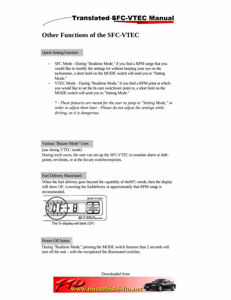
Fuel Delivery Maximized
When the fuel delivery goes beyond the capability of theSFC-mode, then the display will show OF. Lowering the fueldelivery at approximately that RPM range is recommended.
Power Off Status
During "Realtime Mode," pressing the MODE switch formore than 2 seconds will turn off the unit - with the exceptionof the illuminated switches.

Downloaded from
Page 28 of 28
Pressing the MODE switch again will turn on the unit andrestore back to the last used function.

Downloaded from
Page 29 of 29
Troubleshooting the SFC-VTEC
The unit doesn't turn on even when the ignition key is at theON position.
• Check the harness in the rear of the SFC-VTEC to ensure its connection • Make sure that the electrotap connection to the ignition is secure. • You may have grounded the unit to a non-chassis component. Please re-check. • Make sure your unit is not simply turned off. Press the MODE button to see if
it will turn on. • The main switch on the rear of the SFC-VTEC must be in the ON position.
Although my engine revs up, the unit doesn't displayincreasing RPM's.
• Check the harness in the rear of the SFC-VTEC to ensure its connection • Make sure that the electrotap connection to the RPM signal wire is secure. • You may have wired the unit incorrectly. Please re-check with the correct
wiring diagram. • Make sure your unit is not simply turned off. Press the MODE button to see if
it will turn on. • The main switch on the rear of the SFC-VTEC must be in the ON position.
My "Check Engine" lamp comes on.
Scenario One - no "Check Engine" lamp when the unit is OFF, but appears when unit is ON.
• Your sensor line may be switched between positions IN and OUT. Please re-check.
Scenario Two - "Check Engine" lamp appears at all times.
• Check all crimpings, electrotaps, and harnesses to ensure that there is a secure connection.

Downloaded from
Page 30 of 30
My engine stalls, and in general, it doesn't feel right.
• Perhaps your fuel settings are too high or too low? Please test out various settings and adjust accordingly. Also, if you drastically adjust the hi-cam switchover point on a relatively stock car, the acceleration will feel awkward.
• Are you using spark plugs with the appropriate heat settings? If you ran your car hard on the tracks without using the correct plugs, you may shorten the life of your plugs, and not get the proper performance out of your car.