functional safety, bu 0630 - nord drivesystems
TRANSCRIPT

BU 0630 – en
Functional Safety Supplementary manual for series SK 500P

Functional Safety – Supplementary manual for series SK 500P
2 BU 0630 en-2020

1 Introduction
BU 0630 en-2020 3

Functional Safety – Supplementary manual for series SK 500P
4 BU 0630 en-2020
Pos: 3 /Allgemei n/Steuermodule/Inhaltsverzeichnis @ 0\mod_1317978518480_388.docx @ 4078 @ @ 1
Table of Contents === Ende der Liste für Textm arke Inhaltsverzeichnis ===
1 Introduction ................................................................................................................................................. 6 1.1 General .............................................................................................................................................. 6
1.1.1 Documentation ..................................................................................................................... 6 1.1.2 Document history .................................................................................................................. 6 1.1.3 About this manual ................................................................................................................. 7
1.2 Other applicable documents .............................................................................................................. 7 1.3 Presentation conventions ................................................................................................................... 7
1.3.1 Warning information ............................................................................................................. 7 1.3.2 Other information .................................................................................................................. 7
1.4 Safety, installation and application information .................................................................................. 7 2 Function description ................................................................................................................................. 11
2.1 Design of the safe shut-down method .............................................................................................. 11 2.2 Safe shut-down methods ................................................................................................................. 12
2.2.1 Safe Pulse Block ................................................................................................................ 12 2.2.2 Safety Digital Input ............................................................................................................. 13
2.3 Safety functions ............................................................................................................................... 14 2.3.1 Safe Torque Off, STO ......................................................................................................... 14 2.3.2 Safe stop 1 with time control, SS1-t .................................................................................... 15 2.3.3 Priorities and response to faults ......................................................................................... 15
2.4 Examples / Implementation .............................................................................................................. 15 2.4.1 STO function....................................................................................................................... 15 2.4.2 SS1-t function ..................................................................................................................... 19 2.4.3 Simple re-start block ........................................................................................................... 21 2.4.4 Example without Safe Pulse Block ..................................................................................... 22 2.4.5 Exclusion of wiring faults .................................................................................................... 25
3 Assembly and installation ........................................................................................................................ 28 3.1 Installation and assembly ................................................................................................................. 28
3.1.1 Assembly of an SK CU5-STO and SK CU5-MLT customer unit ......................................... 28 3.2 Electrical connection ........................................................................................................................ 29
3.2.1 Wiring guidelines ................................................................................................................ 29 3.2.2 Mains connection ................................................................................................................ 29 3.2.3 Control cable connections .................................................................................................. 31 3.2.4 Control terminal details ....................................................................................................... 31
3.3 Details of the safe shut-down method .............................................................................................. 32 3.3.1 Wiring and shielding ........................................................................................................... 32 3.3.2 Operation with OSSD ......................................................................................................... 32 3.3.2.1 Individual operation 33 3.3.2.2 Multiple device operation 34 3.3.3 EMC ................................................................................................................................... 35
4 commissioning .......................................................................................................................................... 36 4.1 Commissioning steps for STO ......................................................................................................... 36 4.2 SS1-t commissioning steps .............................................................................................................. 37 4.3 Validation ......................................................................................................................................... 40
5 Parameters ................................................................................................................................................. 41 5.1 Parameterisation .............................................................................................................................. 41 5.2 Description of parameters ................................................................................................................ 42
5.2.1 Control terminals ................................................................................................................ 43 5.2.2 Additional parameters ......................................................................................................... 47

1 Introduction
BU 0630 en-2020 5
6 Operating status messages ..................................................................................................................... 48 7 Additional information .............................................................................................................................. 51
7.1 Protective switching devices ............................................................................................................ 51 7.1.1 Output voltage of safety devices ......................................................................................... 51 7.1.2 Switching capacity and current load ................................................................................... 51 7.1.3 OSSD outputs, test pulses ................................................................................................. 53
7.2 Safety categories ............................................................................................................................. 54 7.2.1 IEC 60204-1:2016 .............................................................................................................. 54 7.2.2 IEC 61800-5-2:2016 ........................................................................................................... 54 7.2.3 IEC 61508:2010 .................................................................................................................. 54 7.2.4 ISO 13849-1:2015 .............................................................................................................. 55
8 Technical Data ........................................................................................................................................... 56 8.1 Safe Pulse Block and Safety Digital Input ........................................................................................ 56
9 Appendix .................................................................................................................................................... 58 9.1 Maintenance information .................................................................................................................. 58 9.2 Repair information ............................................................................................................................ 58 9.3 Service and commissioning information ........................................................................................... 59 9.4 Documents and software ................................................................................................................. 59 9.5 Certificates ....................................................................................................................................... 59 9.6 Abbreviations ................................................................................................................................... 60
Pos: 6 /Anl eitung en/El ektr onik /Bussys tem e/Alle Baur eihen/1. (1.)Ei nleitung/!Kapitel Ei nleitung @ 8\m od_1441625462919_388.docx @ 2235978 @ 1 @ 1

Functional Safety – Supplementary manual for series SK 500P
6 BU 0630 en-2020
1 Introduction Pos: 7 /Anl eitung en/El ektr onik /Bussys tem e/Alle Baur eihen/1. (1.)Ei nleitung/!Abschnitt Allgemei nes @ 8\mod_1441352725095_388.docx @ 2235719 @ 2 @ 1
1.1 General Pos: 11 /Anl eitungen/Elek tronik/Safety/1. Einl eitung/D okumentati on (safety) [SK 5xxP] @ 44\m od_1593165143738_388.docx @ 2638668 @ 3 @ 1
1.1.1 Documentation Designation: BU 0630
Part number: 6076302
Series: Functional safety for frequency inverters from the series
NORDAC PRO SK 500P
Scope of application: • Frequency inverters with integrated safety inputs: SK 510P, SK 540P
• Frequency inverters in combination with customer unit extensions with safety inputs: SK 530P, SK 550P
• Customer unit extensions: SK CU5-STO, SK_CU5-MLT
• From NORDAC PRO software version V1.2 R0
Pos: 15 /Anl eitungen/Elek tronik/Safety/1. Einl eitung/D okumenthistorie [Safety : SK 5xxP] @ 44\m od_1594729085636_388.docx @ 2645361 @ 3 @ 1
1.1.2 Document history
Edition Series Version Remarks
Order number Software
BU 0630, July 2020
SK 500P V1.2 R0 First edition
6076302/ 2020 Pos: 16 /Allgem ein/Allgem eing ültige M odul e/---------Seitenum bruch kom pak t --------- @ 13\mod_1476369695906_0.docx @ 2265495 @ @ 1

1 Introduction
BU 0630 en-2020 7
Pos: 17 /Anl eitungen/Elek tronik/Safety/1. Einl eitung/Zu diesem Handbuch [Safety] @ 16\mod_1487169353324_388.docx @ 2327660 @ 3 @ 1
1.1.3 About this manual This manual is intended to help you with the commissioning of the Safe Stop function (STO or SS1-t) with a frequency inverter from Getriebebau NORD GmbH & Co. KG (NORD). It is intended for qualified electricians who plan, install and set up corresponding drive solutions (Section 1.4 "Safety, installation and application information"). The information in this manual assumes that the qualified electricians who are entrusted with this work are familiar with the handling of electronic drive technology, in particular with NORD devices.
This manual only contains information and descriptions of the functional safety and additional information which is relevant for the functional safety of frequency inverters manufactured by Getriebebau NORD GmbH & Co. KG. Pos: 20 /Anl eitungen/Elek tronik/POSIC ON/1. Einl eitung/Mitgel tende D okum ente [POSICON, PLC, Safety ] @ 14\m od_1479993719061_388.docx @ 2308206 @ 2 @ 1
1.2 Other applicable documents This document is only valid in combination with the operating instructions for the frequency inverter which is used. Safe commissioning of the drive application depends on the availability of the information contained in this document.. A list of the documents can be found in Section 9.4 "Documents and software".
The necessary documents can be found under www.nord.com. Pos: 21 /Anl eitungen/Elek tronik/Bussystem e/All e Baurei hen/1. (1.) Einl eitung/!Abschnit t D arstellungskonventi onen @ 8\mod_1441373607811_388.docx @ 2235851 @ 2 @ 1
1.3 Presentation conventions Pos: 22 /Anl eitungen/Elek tronik/Bussystem e/All e Baurei hen/1. (1.) Einl eitung/W arnhinw eise @ 8\m od_1441373791790_388.docx @ 2235882 @ 33 @ 1
1.3.1 Warning information Warning information for the safety of the user and the bus interfaces are indicated as follows:
DANGER
This warning information warns against personal risks, which may cause severe injury or death.
WARNING
This warning information warns against personal risks, which may cause severe injury or death.
CAUTION
This warning information warns against personal risks, which may cause slight or moderate injuries.
NOTICE
This warning warns against damage to material.
1.3.2 Other information
Information This information shows hints and important information.
Pos: 24 /Anl eitungen/Elek tronik/FU und Starter/1. Allgemei nes/Sicherheits- und Installati onshi nweise und War n- Gefahr enhinw eise/neu/Sicher heits-, Installations- und Anw endungshi nweise_01 [alle Geräte - für Handbuecher BU.. ..] @ 17\mod_1488973491253_388.docx @ 2333815 @ 2 @ 1
1.4 Safety, installation and application information Pos: 25 /Anl eitungen/Elek tronik/FU und Starter/1. Allgemei nes/Sicherheits- und Installati onshi nweise und War n- Gefahr enhinw eise/neu/Sicher heits-, Installations- und Anw endungshi nweise_02 [alle Geräte] @ 12\m od_1466690028867_388.docx @ 332586 @ @ 1
Before working on or with the device, please read the following safety instructions extremely carefully. Please pay attention to all other information from the device manual.
Non-compliance can result in serious or fatal injuries and damage to the device or its surroundings.

Functional Safety – Supplementary manual for series SK 500P
8 BU 0630 en-2020
These safety instructions must be kept in a safe place! Pos: 26 /Anl eitungen/Elek tronik/FU und Starter/1. Allgemei nes/Sicherheits- und Installati onshi nweise und War n- Gefahr enhinw eise/neu/Sicher heits- und Installationshi nw eise - Ei nzelpunk te/1. Allgemei n (Sicherheitshinw eise) [SK 2xxE, SK 1xxE] @ 19\m od_1508746494449_388.docx @ 2368636 @ @ 1
1. General Do not use defective devices or devices with defective or damaged housings or missing covers (e.g. blind plugs for cable glands). Otherwise there is a risk of serious or fatal injuries caused by electric shock or bursting electrical components such as powerful electrolytic capacitors.
Unauthorised removal of covers, improper use, incorrect installation or operation causes a risk of serious personal injury or material damage.
During operation and depending on the protection class of the devices, there may be live, bare, moving or rotating parts or hot surfaces.
The device operates with a dangerous voltage. Dangerous voltage may be present at the supply lines, contact strips and PCBs of all connecting terminals (e.g. mains input, motor connection), even if the device is not working or the motor is not rotating (e.g. caused by electronic disabling, jamming of the drive or a short circuit at the output terminals).
The device is not equipped with a mains switch and is therefore always live when connected to the power supply. Voltages may therefore be connected to a connected motor at standstill.
Even if the drive unit has been disconnected from the mains, a connected motor may rotate and possibly generate a dangerous voltage.
If you come into contact with dangerous voltage such as this, there is a risk of an electric shock, which can lead to serious or fatal injuries.
The device and any power plug connectors must not be disconnected while a voltage is applied to the device. Failure to comply with this may cause arcing, which in addition to the risk of injury, also results in a risk of damage or destruction of the device.
The fact that the status LED or other indicators are not illuminated does not indicate that the device has been disconnected from the mains and is without voltage.
The heat sink and all other metal components can heat up to temperatures above 70 °C.
Touching these parts can result in local burns to the body parts concerned (cooling times and clearance from neighbouring components must be complied with).
All work on the device, e.g. transportation, installation, commissioning and maintenance work must be carried out by qualified experts (observe IEC 364 or CENELEC HD 384 or DIN VDE 0100 and IEC 664 or DIN VDE 0110 and national accident prevention regulations). In particular, the general and regional installation and safety regulations for work on high voltage systems (e.g. VDE) must be complied with as must the regulations concerning correct use of tools and the use of personal protection equipment.
During all work on the device, take care that no foreign bodies, loose parts, moisture or dust enter or remain in the device (risk of short circuit, fire and corrosion).
Further information can be found in this documentation. Pos: 28 /Anl eitungen/Elek tronik/FU und Starter/1. Allgemei nes/Sicherheits- und Installati onshi nweise und War n- Gefahr enhinw eise/neu/Sicher heits- und Installationshi nw eise - Ei nzelpunk te/2. Qualifiziertes Fachpersonal ( Sicherheitshinw eise) @ 12\m od_1466690573079_388.docx @ 332620 @ @ 1
2. Qualified experts For the purposes of these basic safety instructions, qualified personnel are persons who are familiar with the assembly, installation, commissioning and operation of this product and who have the relevant qualifications for their work.
Furthermore, the device and the associated accessories may only be installed and started up by qualified electricians. An electrician is a person who, because of their technical training and experience, has sufficient knowledge with regard to
• switching on, switching off, isolating, earthing and marking power circuits and devices, • proper maintenance and use of protective devices in accordance with defined safety standards. Pos: 29 /Anl eitungen/Elek tronik/FU und Starter/1. Allgemei nes/Sicherheits- und Installati onshi nweise und War n- Gefahr enhinw eise/neu/Sicher heits- und Installationshi nw eise - Ei nzelpunk te/3. Bes timmungsgemäße Verwendung – allgem ein ( Sicherheitshi nweise) [alle FU - außer SK 5xxE] @ 12\m od_1466686844876_388.docx @ 332279 @ @ 1

1 Introduction
BU 0630 en-2020 9
3. Correct purpose of use – general The frequency inverters are devices for industrial and commercial systems used for the operation of three-phase asynchronous motors with squirrel-cage rotors and Permanent Magnet Synchronous Motors – PMSM. These motors must be suitable for operation with frequency inverters, other loads must not be connected to the devices.
The devices are components intended for installation in electrical systems or machines.
Technical data and information for connection conditions can be found on the rating plate and in the documentation, and must be complied with.
The devices may only be used for safety functions which are described and explicitly approved.
CE-labelled devices fulfil the requirements of the Low Voltage Directive 2014/35/EU. The stated harmonized standards for the devices are used in the declaration of conformity.
a. Supplement: Correct purpose of use within the European Union
When installed in machines, the devices must not be commissioned (i.e. commencement of proper use) until it has been ensured that the machine fulfils the provisions of EC Directive 2006/42/EC (Machinery Directive); EN 60204-1 must also be complied with. Commissioning (i.e. start-up of proper use) is only permitted if the EMC directive (2014/30/EU) has been complied with.
b. Supplement: Correct purpose of use outside the European Union
The local conditions of the operator for the installation and commissioning of the device must be complied with at the usage location (see also "a) Supplement: Correct purpose of use within the European Union").
Pos: 30 /Anl eitungen/Elek tronik/FU und Starter/1. Allgemei nes/Sicherheits- und Installati onshi nweise und War n- Gefahr enhinw eise/neu/Sicher heits- und Installationshi nw eise - Ei nzelpunk te/4_a. Tr ansport, Ei nlager ung ( Sicherheitshinw eise) @ 19\m od_1508761292824_388.docx @ 2369021 @ @ 1
Transport, storage The information in the manual regarding transport, storage and correct handling must be complied with.
The permissible mechanical and climatic ambient conditions (see technical data in the manual for the device) must be complied with.
If necessary, suitable, adequately dimensioned means of transport (e.g. lifting gear, rope guides) must be used. Pos: 31 /Anl eitungen/Elek tronik/FU und Starter/1. Allgemei nes/Sicherheits- und Installati onshi nweise und War n- Gefahr enhinw eise/neu/Sicher heits- und Installationshi nw eise - Ei nzelpunk te/4_b. Aufstellung und M ontage (Sicher hei tshi nw eise) @ 19\mod_1508741535965_388.docx @ 2368416 @ @ 1
Installation and assembly The installation and cooling of the device must be implemented according to the regulations in the corresponding documentation. The permissible mechanical and climatic ambient conditions (see technical data in the manual for the device) must be complied with.
The device must be protected against impermissible loads. In particular, components must not be deformed and/or insulation distances must not be changed. Touching of electronic components and contacts must be avoided.
The device and its optional modules contain electrostatically sensitive components, which can be easily damaged by incorrect handling. Electrical components must not be mechanically damaged or destroyed. Pos: 32 /Anl eitungen/Elek tronik/FU und Starter/1. Allgemei nes/Sicherheits- und Installati onshi nweise und War n- Gefahr enhinw eise/neu/Sicher heits- und Installationshi nw eise - Ei nzelpunk te/4_c. El ektrischer Anschluss (Sicherheitshinw eise) [dezentral e Ger äte] @ 40\m od_1582025990419_388.docx @ 2590430 @ @ 1
Electrical connection Ensure that the device and the motor are specified for the correct supply voltage.
Installation, maintenance and repair work must not be carried out unless the device has been disconnected from the voltage and at least 5 minutes have elapsed since the mains was switched off! (Due to charged capacitors, the equipment may continue to carry hazardous voltages for up to 5 minutes after being switched off at the mains). Before starting work it is essential to check by measurement that all contacts of the power plug connections or the connection are voltage-free.

Functional Safety – Supplementary manual for series SK 500P
10 BU 0630 en-2020
The electrical installation must be implemented according to the applicable regulations (e.g. cable cross-section, fuses, earth lead connections). Further instructions can be found in the documentation or manual for the device.
Information regarding EMC-compliant installation such as shielding, earthing, location of filters and routing of cables can be found in the documentation for the devices and in the technical information manual TI 80-0011. This information must always be observed even with inverters with a CE label. Compliance with the limit values specified in the EMC regulations is the responsibility of the manufacturer of the system or machine.
In case of a fault, inadequate earthing may result in electric shock, possibly with fatal consequences.
The device may only be operated with effective earth connections which comply with local regulations for large leakage currents (> 3.5 mA). Detailed information regarding connections and operating conditions can be obtained from the technical Information manual TI 80-0019.
Connection of the supply voltage may directly or indirectly set the inverter into operation. Contact with electrically live components will result in electric shock, possibly with fatal consequences.
All poles of cable connections (e.g. power supply) must always be disconnected. Pos: 33 /Anl eitungen/Elek tronik/FU und Starter/1. Allgemei nes/Sicherheits- und Installati onshi nweise und War n- Gefahr enhinw eise/neu/Sicher heits- und Installationshi nw eise - Ei nzelpunk te/4_e. Betrieb (Sicherheitshinw eise (Umrichter)) @ 19\mod_1508746864938_388.docx @ 2368741 @ @ 1
Operation Where necessary, systems in which the devices are installed must be equipped with additional monitoring and protective equipment according to the applicable safety requirements (e.g. legislation concerning technical equipment, accident prevention regulations, etc.).
All covers must be kept closed during operation.
With certain setting conditions, the device or the motor which is connected to it may start automatically when the mains are switched on. The machinery which it drives (press / chain hoist / roller / fan etc.) may then make an unexpected movement. This may cause various injuries, including to third parties.
Before switching on the mains, secure the danger area by warning and removing all persons from the danger area.
Due to its operation, the device produces noises within the audible frequency range. These noises may cause long-term stress, discomfort and fatigue, with negative effects on concentration. The frequency range or the noise can be shifted to a less disturbing or almost inaudible range by adjustment of the pulse frequency. However, this may possibly result in derating (lower power) of the device. Pos: 34 /Anl eitungen/Elek tronik/Safety/2. Sicher heit /Sicherheitshinw eise [Safety] - Störung durch H andfunkgeräte @ 39\m od_1571297002057_388.docx @ 2565250 @ @ 1
The PDS (SR) may suffer interference if mobile radio devices are used within a distance of less than 20 cm from the PDS (SR). Pos: 35 /Anl eitungen/Elek tronik/FU und Starter/1. Allgemei nes/Sicherheits- und Installati onshi nweise und War n- Gefahr enhinw eise/neu/Sicher heits- und Installationshi nw eise - Ei nzelpunk te/4_f. War tung, Ins tandhaltung und Außer betriebnahm e ( Sicherheitshinw eise) @ 19\m od_1508748695495_388.docx @ 2368881 @ @ 1
Maintenance, repair and decommissioning Installation, maintenance and repair work must not be carried out unless the device has been disconnected from the voltage and at least 5 minutes have elapsed since the mains was switched off! (Due to charged capacitors, the equipment may continue to carry hazardous voltages for up to 5 minutes after being switched off at the mains). Before starting work it is essential to check by measurement that all contacts of the power plug connections or the connection are voltage-free.
For further information, please refer to the manual for the device. Pos: 37 /Anl eitungen/Elek tronik/FU und Starter/1. Allgemei nes/Sicherheits- und Installati onshi nweise und War n- Gefahr enhinw eise/neu/Sicher heits- und Installationshi nw eise - Ei nzelpunk te/5. Expl osionsg efähr dete Umg ebung (ATEX) [SK xxxE-FDS, SK 5xxE] @ 12\m od_1466688226647_388.docx @ 332517 @ @ 1
4. Potentially explosive environment (ATEX) The device is not approved for operation or maintenance work in potentially explosive environments (ATEX). Pos: 39 /Anl eitungen/Elek tronik/Safety/3. Funkti onsbeschrei bung/Funk tionsbeschr eibung _01 [Überschrift] @ 15\mod_1484812699011_388.docx @ 2312909 @ 1 @ 1

2 Function description
BU 0630 en-2020 11
2 Function description Pos: 40 /Anl eitungen/Elek tronik/Safety/3. Funkti onsbeschrei bung/Funk tionsbeschr eibung _02 @ 15\mod_1484812747040_388.docx @ 2312945 @ @ 1
To avoid danger to persons and to prevent damage to material, machines must be able to be switched off safely. The frequency inverters stated in this document provide safe shut-down methods.
The following basic explanation of the function of a frequency inverter serves to provide better understanding of the function of safe shut-down methods:
The mains voltages are rectified and the resulting DC links circuit voltage is reconverted to AC according to the requirements of the operating status of the motor (frequency and voltage).
The semiconductor switches of the inverter (T1 to T6) are controlled by a highly complex pulse pattern. This pulse pattern is generated by the micro-controller (µC) and amplified by the driver. The drivers convert the logic signals on the control voltages of the semiconductor switch. The semiconductor switches are switched via the control voltage and the pulse pattern is amplified and applied to the motor terminals. Due to the low-pass effect of the motor, a three-phase pulse width modulated sine wave voltage, a three-phase system, results from the pulsed voltage. The motor generates a torque. Pos: 44 /Anl eitungen/Elek tronik/Safety/3. Funkti onsbeschrei bung/Funk tionsbeschr eibung _03 [SK 5xxP] @ 44\m od_1594729359570_388.docx @ 2645399 @ 2 @ 1
2.1 Design of the safe shut-down method Structure of the Safe Pulse Block for SK 510P, SK 540P
1 Safety Digital Input 2 Micro-controller 3 Driver 4 Safe Pulse Block

Functional Safety – Supplementary manual for series SK 500P
12 BU 0630 en-2020
Structure of the Safe Pulse Block for SK 530P, SK 550P with SK CU5-STO or SK CU5-MLT
1 Safety Digital Input 2 Micro-controller 3 Driver 4 Safe Pulse Block
By the use and combination of the safe shut-down methods Safe Pulse Block and/or Safety Digital Input, the safety-related stop functions STO and SS1, as well as a simple restart block, can be implemented with various safety and performance levels. Pos: 46 /Allgem ein/Allgem eing ültige M odul e/---------Seitenum bruch kom pak t --------- @ 13\mod_1476369695906_0.docx @ 2265495 @ @ 1 Pos : 48 /Anl eitungen/Elek tronik/Safety/3. Funkti onsbeschrei bung/Sichere Abschaltw ege_01 [SK 500P] @ 40\mod_1574333326841_388.docx @ 2577707 @ 2 @ 1
2.2 Safe shut-down methods Two safe shut-down methods are available for SK 500P series frequency inverters:
1. SK 510P and SK 540P are equipped with a permanently installed safety module. 2. SK 530P and SK 550P can be equipped with optional control terminals. The plug-in modules
SK CU5-SSTO and SK CU5-MLT provide safe shut-down methods.
Both variants provide the following safe shut-down methods:
• Safe Pulse Block • Safety Digital Input
With the aid of safe shut-down methods, the following safe stop functions can be implemented:
• STO (Safe Torque Off) safely switched off torque • SS1-t (Safe Stop 1 time controlled) Pos: 53 /Anl eitungen/Elek tronik/Safety/3. Funkti onsbeschrei bung/Sichere Pulssperre_01 [SK 500P] @ 44\mod_1594729516977_388.docx @ 2645437 @ 3 @ 1
2.2.1 Safe Pulse Block With the aid of an additional DC/DC converter, the Safe Pulse Block generates the supply voltage for the drivers. For this, the Safe Pulse Block must be provided with a 24 V voltage or two 24 V voltages. This must be provided as follows:
• SK 510P, SK 540P: 1 x 24 V via contact VIS_24V with reference potential VIS_0V • SK 530P, SK 550P with SK CU5-STO or SK CU5-MLT: 2 x 24 V via contacts VIS1_24V and
VIS2_24V with common reference potential VIS12_0V Pos: 55 /Anl eitungen/Elek tronik/Safety/3. Funkti onsbeschrei bung/Sichere Pulssperre_02 [SK 500P] @ 44\mod_1594729769814_388.docx @ 2645475 @ @ 1
If this 24 V voltage is switched off, the DC/DC converter does not transmit any power to the drivers. As the drivers are now no longer supplied with power, no pulses reach the semiconductor switches (T1 to T6) of the inverter. The flow of current in the semiconductor switches and in the motor is interrupted. I.e. after a certain response time of the electronics and the reduction of the motor current, the motor does not develop a driving torque.
Switch-off of the 24 V voltages must be performed by a fail-safe switching device. This can be implemented in various ways, depending on the safe shut-down method.

2 Function description
BU 0630 en-2020 13
SK 510P, SK 540P
For this, either the VIS_24V or VIS_0V contact may be disconnected from the 24 V voltage source. Preferably, the VIS_24V contact is disconnected.
SK 530P, SK 550P with SK CU5-STO or SK CU5-MLT
This variant has a dual-channel input circuit. Contacts VIS1_24V and VIS2_24V have a common reference potential VIS12_0V. This reference potential must not be disconnected if a dual-channel Safe Pulse Block is used. With this variant, the Safe Pulse Block can also be used with a single channel. I.e. the two contacts VIS1_24V and VIS2_24V are connected in parallel.
In this case, both the 24 V voltage as well as the reference potential VIS12_0V can be disconnected. Preferably, the parallel contacts VIS1_24V and VIS2_24V are separated. Pos: 56 /Anl eitungen/Elek tronik/Safety/3. Funkti onsbeschrei bung/Safety Digital eingang [SK 500P] @ 40\m od_1574336094503_388.docx @ 2578102 @ 3 @ 1
2.2.2 Safety Digital Input The Safety Digital Input is explicitly intended for implementing a safety function. This means that the standard digital inputs must not be used to implement a safety function.
With the Safety Digital Input, safe triggering is carried out using the micro-controller. This interrupts the control signal to the drivers or provides a pulse pattern which shuts down the connected motor.
The Safety Digital Input can be parameterised with the following functions:
• Disable Voltage
The micro-controller interrupts the control signals to the drivers. No control pulses are provided to the semiconductor switches (T1 to T6) of the inverter. I.e. the current in the semiconductor switches and in the motor is interrupted and the motor runs down to a standstill.
• Quick Stop
The micro-controller shuts down the motor with control pulses according to a pre-set quick stop time.
With regard to function, the Safety Digital Input is identical for the two variants of the safe shut-down method. However, there are differences with regard to the reference potential.

Functional Safety – Supplementary manual for series SK 500P
14 BU 0630 en-2020
SK 510P, SK 540P
In this case the Safety Digital Input with contact VISD_24V has the reference potential GND. This is the same reference potential as for all other analogue and digital inputs and outputs of the frequency inverter. For this reason, the Safety Digital Input cannot be triggered by disconnecting the reference potential.
SK 530P, SK 550P with SK CU5-STO or SK CU5-MLT
The Safety Digital Input of the CU5 modules has a separate reference potential VISD_0V. I.e. in this case this reference potential can be disconnected to trigger the Safety Digital Input. Preferably, the VISD_24V contact is disconnected Pos: 63 /Allgem ein/Allgem eing ültige M odul e/---------Seitenum bruch kom pak t --------- @ 13\mod_1476369695906_0.docx @ 2265495 @ @ 1 Pos : 64 /Anl eitungen/Elek tronik/Safety/3. Funkti onsbeschrei bung/Sicherheitsfunkti onen @ 15\m od_1485168492973_388.docx @ 2314154 @ 2 @ 1
2.3 Safety functions Pos: 65 /Anl eitungen/Elek tronik/Safety/3. Funkti onsbeschrei bung/WARNUN G - Versagen einer Bremse @ 39\m od_1570798924238_388.docx @ 2563904 @ @ 1
WARNING Mechanical brake failure Control of a mechanical brake by means of the frequency inverter is not fail-safe. Triggering of the STO and the fault response function causes the application of a mechanical brake which is controlled by the frequency inverter. The brake takes the entire load of the drive units and all of its rotating masses and attempts to stop it.
A brake which is not designed to take the full load (e.g. a holding brake) may be damaged and may fail. This can cause severe or fatal injuries or damage to the equipment, e.g. due to falling loads.
• Design the brake as an operating brake • Ensure that the drive unit is stopped before the STO function is activated. Pos: 68 /Anl eitungen/Elek tronik/Safety/3. Funkti onsbeschrei bung/Sicherheitsfunkti onen_Sicher abg eschaltetes M om ent, STO @ 15\m od_1485168854901_388.docx @ 2314190 @ 3 @ 1
2.3.1 Safe Torque Off, STO The STO function prevents the supply of motive power to the motor. According to ISO 1411, this function can be used to prevent unexpected starting and/or switch off the driving torque as quickly as possible (see technical data response time) and allow the drive run down to a standstill (motor with work machine).
This behaviour corresponds to stop category 0 (uncontrolled stopping) according to EN 60204-1. Depending on the application the movement while running down to a standstill can cause a hazard for an undefined time. Detection of whether or when the drive unit has achieved a safe state is not integrated into the frequency inverter.
Depending on the switching equipment and use of a safe shut-down method, an STO function with safety category 4 as per DIN EN ISO 13849-1 can be implemented. Pos: 69 /Anl eitungen/Elek tronik/Safety/3. Funkti onsbeschrei bung/Sicherheitsfunkti onen_Sicher abg eschaltetes M om ent Ergänzung, STO [SK 500P] @ 44\m od_1593153101665_388.docx @ 2638250 @ @ 1
Bei einer Synchronmaschine kann es beim Versagen des Leistungsteils des Frequenzumrichters trotz aktivierter STO-Funktion zu einer Ausrichtbewegung um eine Polteilung kommen.
Das verknüpfte Bild kann nicht angezeigt werden. Möglicherweise wurde die Datei verschoben, umbenannt oder gelöscht. Stellen Sie sicher, dass die Verknüpfung auf die korrekte Datei und den korrekten Speicherort zeigt.

2 Function description
BU 0630 en-2020 15
Pos: 72 /Anl eitungen/Elek tronik/Safety/3. Funkti onsbeschrei bung/Sicherheitsfunkti onen_Sicherer Stopp mit Zeitsteuer ung, SS1-t [SK 500P] @ 40\m od_1574336646834_388.docx @ 2578141 @ 3 @ 1
2.3.2 Safe stop 1 with time control, SS1-t SK 500P series frequency inverters support implementation of the SS1 function in the variant SS1-t (safe stop 1 with time control).
To stop the motor, the frequency inverter triggers a quick stop. After a time which is specific to the application the STO function can be switched on. This behaviour corresponds to stop category 1 (controlled stopping) according to IEC 60204-1. The changeover to the STO function is time-controlled via an external, fail-safe time relay (delayed output of an external safety device).
Information Controlled stopping Controlled stopping is triggered via the Safety Digital Input and meets lower safety requirements than the STO function, which is triggered via the Safe Pulse Block.
Controlled stopping with SS1-t can fail without detection and must not be used if this failure can cause a hazardous situation in the application.
Pos: 73 /Anl eitungen/Elek tronik/Safety/3. Funkti onsbeschrei bung/Pri oritäten und Fehlerreak tion [SK 500P] @ 44\m od_1594730066229_388.docx @ 2645512 @ 3 @ 1
2.3.3 Priorities and response to faults As the Safe Pulse Block is based on switching off the supply voltage to the drivers of the inverter’s semiconductor switches (T1 to T6), this shut-down method has the highest priority. I.e. if the safety function STO is implemented with the Safe Pulse Block, the safety function STO also has the highest priority. If the safety functions STO and SS1-t are implemented in parallel, it must be noted that controlled stopping of the motor via the Safety Digital Input is interrupted by triggering the Safe Pulse Block.
The Safety Digital Input has an internal fault diagnosis. If this diagnosis detects a fault, the control signals to the drivers of the semiconductor switches (T1 to T6) of the inverter are switched off. This fault response corresponds to the behaviour of the safety function STO with the special feature that this fault state can only be acknowledged by resetting the mains voltage of the frequency inverter. Acknowledgement via a bus system or the digital inputs is not possible.
NOTE: The SS1-t function must not be used if a hazardous situation can result in the application due to the fault response. Pos: 76 /Allgem ein/Allgem eing ültige M odul e/---------Seitenum bruch kom pak t --------- @ 13\mod_1476369695906_0.docx @ 2265495 @ @ 1 Pos : 78 /Anl eitungen/Elek tronik/Safety/3. Funkti onsbeschrei bung/Beispiel e / Realisier ung/Beispi ele / R ealisi erung [SK 500P] @ 40\mod_1580802975694_388.docx @ 2588400 @ 2 @ 1
2.4 Examples / Implementation The following shows some examples of solutions for the safety functions STO and SS1-t. Pos: 79 /Anl eitungen/Elek tronik/Safety/3. Funkti onsbeschrei bung/Beispiel e / Realisier ung/Funkti on STO_01 @ 15\m od_1485263814224_388.docx @ 2314825 @ 3 @ 1
2.4.1 STO function Implementation of a safety function usually requires the use of a protective switching device. The category of the function is determined by the component with the lowest category. Pos: 83 /Anl eitungen/Elek tronik/Safety/3. Funkti onsbeschrei bung/Beispiel e / Realisier ung/Funkti on STO_02 [SK 5xxP] @ 44\m od_1594730243433_388.docx @ 2645550 @ @ 1

Functional Safety – Supplementary manual for series SK 500P
16 BU 0630 en-2020
SK 510P, SK 540P
1 Supply voltage 2 Reset circuit 3 Input circuit with cross-circuit detection 4 Safety output
SK 530P, SK 550P with SK CU5-STO or SK CU5-MLT
1 Supply voltage 2 Reset circuit 3 Input circuit with cross-circuit detection 4 2 x safety output with a common reference (GND)

2 Function description
BU 0630 en-2020 17
If the Safe Pulse Block is triggered for an enabled frequency inverter, this results in the error E018 (18.0 “Safety circuit”). To prevent this, the Safety Digital Input can additionally be used with the Voltage Disable function (P424 = 1).
The typical response time can be reduced by additional use of the Safety Digital Input. A second safety output is required to control this.
This solution is preferable, especially in cases where the switching device only checks its safety outputs in the course of an enabling cycle, as is the case with some electro-mechanical switching devices. A suitable inspection interval must be specified according to the safety requirements.
SK 510P, SK 540P
1 Supply voltage 2 Reset circuit 3 Input circuit with cross-circuit detection 4 Safety output 5 Safety output

Functional Safety – Supplementary manual for series SK 500P
18 BU 0630 en-2020
SK 530P, SK 550P with SK CU5-STO or SK CU5-MLT
1 Supply voltage 2 Reset circuit 3 Input circuit with cross-circuit detection 4 Safety output 5 2 x safety output with a common reference (GND)
A separate shielded cable must be used to connect each of the safety outputs. However, with the use of a protective switching device with cross-circuit monitoring of OSSD outputs, the cables of both safety outputs can also be run in a common shielded cable.
The requirements for category 4 and PL e are only fulfilled by the Safe Pulse Block. The Safety Digital Input only achieves category 2 and PL d (Performance Level d).
During the period between activation of the safety function via the Safety Digital Input and activation of the STO via the Safe Pulse Block, the frequency inverter can also only fulfil category 2 and PL d. Pos: 94 /Allgem ein/Allgem eing ültige M odul e/---------Seitenum bruch kom pak t --------- @ 13\mod_1476369695906_0.docx @ 2265495 @ @ 1

2 Function description
BU 0630 en-2020 19
Pos: 96 /Anl eitungen/Elek tronik/Safety/3. Funkti onsbeschrei bung/Beispiel e / Realisier ung/Funkti on SS1-t [SK 500P] @ 44\mod_1594209009459_388.docx @ 2643823 @ 3 @ 1
2.4.2 SS1-t function The Safety Digital Input with the Quick Stop function (P424 = 2) is always required to implement the function SS1-t.
SK 510P, SK 540P
1 Supply voltage 2 Reset circuit 3 Input circuit with cross-circuit detection 4 Safety output 5 Safety output, delayed by a safety timing element

Functional Safety – Supplementary manual for series SK 500P
20 BU 0630 en-2020
SK 530P, SK 550P with SK CU5-STO or SK CU5-MLT
1 Supply voltage 2 Reset circuit 3 Input circuit with cross-circuit detection 4 Safety output 5 2 x safety output with a common reference (GND), delayed by a safety timing element
Actuation of the emergency stop button (call-up of the safety function) initially triggers a controlled stopping action via the Safety Digital Input. In this case, it must be ensured that the drive is brought to standstill within the parameterised “Quick stop time” (P426). After the elapse of a delay time which is controlled by the protective switching device, the STO function is triggered via the Safe Pulse Block. The delay time must be dimensioned so that the delay is longer than the quick stop time plus the “DC Run-on time” (P559). The delay time must be selected so as to be fail-safe.
After the delay time which is set in the protective switching device has elapsed, the frequency inverter always switches to the STO function. This also applies in the case of failure of the controlled stopping action.
SK 500P series frequency inverters are equipped with additional control which is set via the “Safety SS1 max. time” parameter (P423). If the motor is not stopped within the “Safety SS1 max time” (P423), the frequency inverter performs the fault response action and generates an error message. I.e. in this case the motor also runs down to a standstill.
A separate shielded cable must be used to connect each of the safety outputs. If a protective switching device with cross-circuit monitoring of OSSD outputs is used, the cables of both safety outputs can also be run in a common shielded cable.
The requirements for category 4 and PL e are only fulfilled by the Safe Pulse Block. The Safety Digital Input only achieves category 2 and PL d (Performance Level d).
During the period between activation of the SS1-t safety function via the Safety Digital Input and activation of the STO function via the Safe Pulse Block, the frequency inverter can also only fulfil the requirements of category 2 and PL d. Pos: 103 /Allgem ein/Allgem eingültig e Module/---------Seitenumbr uch kompakt --------- @ 13\m od_1476369695906_0.docx @ 2265495 @ @ 1

2 Function description
BU 0630 en-2020 21
Pos: 104 /Anleitungen/El ektr onik /Safety /3. Funktionsbeschr eibung/Beispi ele / R ealisierung/Ei nfache Wieder anl aufsperre_01 @ 44\m od_1594730617062_388.docx @ 2645587 @ 3 @ 1
2.4.3 Simple re-start block Category 4 as per DIN EN ISO 13849-1 can be achieved with direct dual-channel triggering of the Safe Pulse Block using a safe switching element. The following illustrations show typical examples with an emergency stop button (positively driven contacts, category 4). Pos: 106 /Anleitungen/El ektr onik /Safety /3. Funktionsbeschr eibung/Beispi ele / R ealisierung/Ei nfache Wieder anl aufsperre_02 [SK 500P] @ 40\mod_1574410758936_388.docx @ 2578260 @ @ 1
SK 510P, SK 540P
Emergency stop button Shielded cables 1) Frequency inverter
1) Shielded cables to exclude faults as per DIN EN ISO 13849-2
SK 530P, SK 550P with SK CU5-STO or SK CU5-MLT
Emergency stop button Shielded cables 1) Frequency inverter
1) Shielded cables to exclude faults as per DIN EN ISO 13849-2
or
Emergency stop button Shielded cables 1) Frequency inverter
1) Shielded cables to exclude faults as per DIN EN ISO 13849-2 Pos: 107 /Anleitungen/El ektr onik /Safety /3. Funktionsbeschr eibung/Beispi ele / R ealisierung/Ei nfache Wieder anl aufsperre_03 @ 44\m od_1594731364124_388.docx @ 2645625 @ @ 1
To achieve safety category 4, fault exclusion as per DIN EN ISO 13849-2 Section D.5 must be possible for the upstream components (hard-wiring and dual-channel button with independent, positive-opening contacts). I.e., in this example, the emergency-stop button and the wiring must be designed so that short-circuiting at the emergency-stop button and short-circuits to other live systems can be ruled out.

Functional Safety – Supplementary manual for series SK 500P
22 BU 0630 en-2020
In this example, there is no reset circuit as is the case with the protective switching devices. If the result of risk analysis shows that cancellation of the stop command must be acknowledged by a deliberate manual action, the resetting requirements can be fulfilled organisationally (e.g. by an emergency stop button with key release and storage of the key away from the machine).
If the Safe Pulse Block is triggered for an enabled frequency inverter, this results in the error E018 (18.0 “Safety circuit”).
Information With the Automatic Fault Acknowledgement (P506) and Automatic Starting (P428) functions (see BU 0600), the drive starts immediately after the emergency stop button is released. For this reason, it is urgently recommended that these functions are not used in combination and especially not for safety-relevant applications.
Pos: 108 /Allgem ein/Allgem eingültig e Module/---------Seitenumbr uch kompakt --------- @ 13\m od_1476369695906_0.docx @ 2265495 @ @ 1 Pos : 110 /Anleitungen/El ektr onik /Safety /3. Funktionsbeschr eibung/Beispi ele / R ealisierung/Beispiel ohne sichere Pulssperre [SK 500P] @ 44\mod_1594731483237_388.docx @ 2645662 @ 35 @ 1
2.4.4 Example without Safe Pulse Block
WARNING Hazardous movement If the safety functions STO/SS1-t are exclusively implemented via the Safety Digital Input, the drive can be unexpectedly supplied with power at any time, even after it has been stopped. Under some circumstances this may cause hazardous movement. In this case, the fault response action is performed at the latest after the maximum fault response time (see technical data 35 ms).
• Implement the safety function with the Safe Pulse Block.
It is possible to implement the safety function STO or SS1 with the Safety Digital Input and a protective switching device only. However, according to DIN EN ISO 13849-1, with this switching variant, the maximum safety category that can be achieved is category 2. However, the condition for this is that in addition to the digital input, all other components (protective switching device, emergency stop button, wiring) also fulfil the requirements for category 2.

2 Function description
BU 0630 en-2020 23
SK 510P, SK 540P
Emergency stop button
Safety switching device Shielded cables 1)
Frequency inverter
Use of a digital input Reset
1) Shielded cables to exclude faults as per DIN EN ISO 13849-2
1 Supply voltage 2 Reset circuit 3 Input circuit with cross-circuit detection 4 Safety output

Functional Safety – Supplementary manual for series SK 500P
24 BU 0630 en-2020
SK 530P, SK 550P with SK CU5-STO or SK CU5-MLT
Emergency stop button
Safety switching device Shielded cables 1)
Frequency inverter
Use of a digital input Reset
1) Shielded cables to exclude faults as per DIN EN ISO 13849-2
1 Supply voltage 2 Reset circuit 3 Input circuit with cross-circuit detection 4 Safety output
To implement the STO safety function, the Safety Digital Input is parameterised to the Voltage Disable function (P424 = 1). The Safety Digital Input with the Quick Stop function (P424 = 2) is parameterised for implementation of the SS1-t function. The quick stop time is set via parameter P426. It must be ensured that the drive is actually brought to standstill within the parameterised quick stop time.
Information Category Implementation of safety switching with only the Safety Digital Input as described above only enables compliance with safety category 2 or Performance Level d, as a maximum (see 8.1 "Safe Pulse Block and Safety Digital Input").
This switching version should therefore only be considered if only low requirements for functional safety need to be fulfilled and if the risk assessment has shown that failure of the safety function can only result in slight (usually temporary) injuries. In case of doubt, the Safe Pulse Block should always be used (see 2.2.1 "Safe Pulse Block"). Pos: 111 /Allgem ein/Allgem eingültig e Module/---------Seitenumbr uch kompakt --------- @ 13\m od_1476369695906_0.docx @ 2265495 @ @ 1

2 Function description
BU 0630 en-2020 25
Pos: 113 /Anleitungen/El ektr onik /Safety /3. Funktionsbeschr eibung/Beispi ele / R ealisierung/Fehl erausschluss für die Verdr ahtung_01 [SK 500P] @ 40\mod_1580804699343_388.docx @ 2588437 @ 3 @ 1
2.4.5 Exclusion of wiring faults In the examples above, a separate shielded cable, with the shield connected at both ends is used for each of the inputs which are used to implement the safety function (also refer to the following illustration). These measures are used to rule out faults as per DIN EN ISO 13849-2 in case of a short circuit between any of the conductors.
This exclusion of faults is necessary in order to fulfil the requirements of safety category 4 as per DIN EN ISO 13849-1. This means that, neither a single detected fault or an accumulation of undetected faults can result in the loss of the safety function. A short circuit from an external voltage, e.g. from a 24V control cable, to the 24V input of a safe shut-down method could lead to the loss of a safety function I.e. this fault must be prevented by means of suitable measures.
It is not essential to use a separate shielded cable for each input. For example, the cables for the Safety Digital Input and the Safe Pulse Block may be jointly run in a shielded cable if the monitored safety outputs of the switching device are equipped with cross-circuit detection (refer to the following illustration). If necessary, the effectiveness of the cross-circuit detection must be demonstrated. Pos: 117 /Allgem ein/Allgem eingültig e Module/---------Seitenumbr uch kompakt --------- @ 13\m od_1476369695906_0.docx @ 2265495 @ @ 1

Functional Safety – Supplementary manual for series SK 500P
26 BU 0630 en-2020
Pos: 118 /Anleitungen/El ektr onik /Safety /3. Funktionsbeschr eibung/Beispi ele / R ealisierung/Fehl erausschluss für die Verdr ahtung_02 [SK 5xxP] @ 44\mod_1594731666736_388.docx @ 2645701 @ @ 1
SK 510P, SK 540P SK30P, SK 550P with SK CU5-STO or SK CU5-MLT
Safety output on protective device
Shielded cables 1)
Frequency inverter
Safety output on protective device
Shielded cables 1)
Frequency inverter
Use of Safe Pulse Block
Use of Safe Pulse Block
Mon
itore
d ou
tput
s w
ithou
t cro
ss-c
ircui
t det
ectio
n
Output 1
Output 2
or
Output 1
Output 2
Output 3
or
Output 1
Output 2
Mon
itore
d ou
tput
s w
ith c
ross
-ci
rcui
t det
ectio
n
Output 1
Output 2
1) Shielded cables to exclude faults as per DIN EN ISO 13849-2 Pos: 120 /Anleitungen/El ektr onik /Safety /3. Funktionsbeschr eibung/Beispi ele / R ealisierung/Fehl erausschluss für die Verdr ahtung_03 [SK 500P] @ 44\mod_1593153457758_388.docx @ 2638288 @ 5 @ 1
Other measures (separate cable duct, installation in armoured conduit, etc.) are possible. More precise details result from the risk assessment and the FMEA for the specific application.
For the Safe Pulse Block it is also conceivable that this could be triggered via two safety outputs, one switching the 24 V output and the other one switching the GND output. For restrictions, refer to 2.2.1 "Safe Pulse Block"

2 Function description
BU 0630 en-2020 27
Monitored outputs
SK 510P, SK 540P SK30P, SK 550P with SK CU5-STO or SK CU5-MLT Safety output on the protective switching device
Connecting cables
Frequency inverter Safety output on the protective switching device
Connecting cables Frequency inverter
Use of Safe Pulse Block
Use of Safe Pulse Block
In this case, a shielded cable is not necessarily essential if the safety outputs are monitored. If, for example, other 24 V control cables are installed in the same cable duct and a fault in the form of a short-circuit of the output of the protective switching device (24 V) to a control cable (= 24 V) is assumed, this fault would be detected by the output monitoring of the switching device and the Safe Pulse Block would be triggered by the second safety output. Dangerous situations may occur with a short-circuit of a control cable (= 24 V) to both safety outputs (24 V). More precise details result from the risk assessment and the FMEA for the specific application.
If no shielded cable is used for wiring the safety function, possible effects of electromagnetic fields must be taken into account. Hence, the use of a 1 m long cable (in a separate cable duct) in an environment without strong electromagnetic fields is relatively safe, whereas the installation of a long cable in the direct vicinity of a powerful transmitter or a medium voltage distributor may cause failure of the safety function. Because of this, use of shielded cables is generally recommended. Pos: 122 /Anleitungen/El ektr onik /Safety /4. M ontage und Installation/M ontag e und Ins tallation (Ü berschrift +) @ 15\m od_1485428773104_388.docx @ 2316139 @ 1 @ 1

Functional Safety – Supplementary manual for series SK 500P
28 BU 0630 en-2020
3 Assembly and installation
The installation instructions contained in this manual only deal with issues that are related to functional safety. For further information, please refer to the manual for the relevant frequency inverter (BU 0600). Pos: 123 /Anleitungen/El ektr onik /Safety /4. M ontage und Installation/Einbau und Montage_01 @ 15\mod_1485429630421_388.docx @ 2316175 @ 2 @ 1
3.1 Installation and assembly The installation instructions in BU 0600 must be observed! Pos: 124 /Anleitungen/El ektr onik /Safety /4. M ontage und Installation/Einbau und Montage_02 [SK 5xxE] @ 15\mod_1485429733283_388.docx @ 2316211 @ @ 1
The frequency inverter must comply with protection class IP20. It must be installed in an adequately ventilated installation space with protection class IP54 (or higher). Pos: 125 /Technische Inform ati onen/Sonstige Dokum ente/TI 80_0030 - Funktionale Sicher heit NORD AC PRO SK 5xxP/Montage ei ner Kundenschnitts tell e SK C U5 [SK 500P] @ 44\mod_1593173350122_388.docx @ 2638821 @ 3 @ 1
3.1.1 Assembly of an SK CU5-STO and SK CU5-MLT customer unit
DANGER Danger of electric shock The frequency inverter has a hazardous voltage for up to 5 minutes after it has been switched off.
• Only carry out work when the frequency inverter has been disconnected and at least 5 minutes have elapsed since the mains was switched off!
Installation must be carried out as follows:
1. Switch off the mains voltage, observe the waiting period. 2. Push the control terminal cover down and remove it. 3. Remove the blank cover by activating the release mechanism at the lower edge and removing it
with an upward rotating movement. 4. Break out the internal jumper of the STO contact with the aid of a small screwdriver or small
needle-nose pliers. Otherwise the customer unit cannot be installed.
Information Once the jumper has been removed, the frequency inverter cannot be operated with functional safety without CU5.
5. Hook the customer unit onto the upper edge and press in lightly until it engages. Take care that the connector strip makes proper contact.
6. Install the control terminals and blank cover.

3 Assembly and installation
BU 0630 en-2020 29
Remove the control terminals and blank cover.
Remove the STO contact jumper.
Install the SK CU5-STO customer unit.
Install the control terminals and blank cover.
Pos: 126 /Anleitungen/El ektr onik /Safety /4. M ontage und Installation/Elek trischer Anschl uss_01 @ 15\mod_1485429904375_388.docx @ 2316246 @ 2 @ 1
3.2 Electrical connection The information for installation or electrical connection from the manual BU 0600 as well as all of the following information must be observed. Pos: 127 /Anleitungen/El ektr onik /FU und Starter/1. Allgemei nes /Sicherheits- und Ins tall ationshinw eise und W arn- Gefahrenhinw eise/Sicherheitshinw eise (auslaufend)/verschiedene/W ARNUNG - El ektrischer Schlag ( nicht unter Spannung ar beiten) @ 14\m od_1480331381423_388.docx @ 2308485 @ @ 1
WARNING Electric shock
Touching electrically conducting components may cause an electric shock and severe or possibly fatal injury. • Disconnect the frequency inverter from the power supply before starting installation work. • Only work on devices which have been disconnected from the power supply. Pos: 128 /Anleitungen/El ektr onik /FU und Starter/1. Allgemei nes /Sicherheits- und Ins tall ationshinw eise und W arn- Gefahrenhinw eise/Sicherheitshinw eise (auslaufend)/verschiedene/W ARNUNG - El ektrischer Schlag (W artezeit) @ 14\mod_1480332099956_388.docx @ 2308520 @ @ 1
WARNING Electric shock
The frequency inverter carries hazardous voltage for up to 5 minutes after being switched off. • Only start work after a waiting period of at least 5 minutes after switching off the mains supply
(disconnection). Pos: 130 /Anleitungen/El ektr onik /Safety /4. M ontage und Installation/Ver drahtungsrichtlini en [BU0630] @ 44\m od_1593153830132_388.docx @ 2638326 @ 3 @ 1
3.2.1 Wiring guidelines Wire end sleeves must be used if flexible cables (multiple strand or fine-wire) are used for the connections X19 (at position X17) or X20. In addition, the wiring guidelines in the frequency inverter manual (BU 0600) also apply. Pos: 132 /Anleitungen/El ektr onik /Safety /4. M ontage und Installation/N etzanschl uss [BU0630] @ 40\m od_1578408046098_388.docx @ 2582167 @ 3 @ 1
3.2.2 Mains connection Devices for implementation of a safety function must only be operated on TN, TT and IT networks. Grounded Corner operation is not intended.
For operation in IT networks
• the IT network screws must be removed • a braking resistor must be used Pos: 133 /Anleitungen/El ektr onik /FU und Starter/1. Allgemei nes /Sicherheits- und Ins tall ationshinw eise und W arn- Gefahrenhinw eise/neu/War n- und Gefahrenhinw eise/ACHTUN G - Betrieb am IT – Netz [SK 5xxP] @ 32\m od_1553605071546_388.docx @ 2520590 @ @ 1

Functional Safety – Supplementary manual for series SK 500P
30 BU 0630 en-2020
NOTICE! Operation in IT networks If a mains fault (short-circuit to earth) occurs in an IT network, the link circuit of a connected frequency inverter may become charged, even if it is switched off. This results in destruction of the link circuit capacitors due to overcharging.
• Connect a braking resistor to dissipate excess energy. Pos: 134 /Anleitungen/El ektr onik /FU und Starter/1. Allgemei nes /Sicherheits- und Ins tall ationshinw eise und W arn- Gefahrenhinw eise/neu/War n- und Gefahrenhinw eise/ACHTUN G - Betrieb am IT-N etz [SK 5xxP] @ 44\mod_1594793582287_388.docx @ 2645740 @ @ 1
NOTICE! Operation in IT networks If a fault is detected in the safety circuit of the Safety Digital Input, pulse generation by the frequency inverter is switched off. This also affects control of the brake chopper. If the Safety Digital Input is used (P424 = 1 or P424 = 2), possible triggering faults are:
• Detected fault in the Safety Digital Input hardware • “Safety SS1 max. time” (P423) exceeded • Incorrect input of the “Safety CRC” (P499) checksum or the password (P497, P498).
If such a fault occurs, and at the same time there is an earth fault in the IT network, the frequency inverter cannot be protected against possible overcharging of the link circuit capacitors. The frequency of hardware faults is very low, so that special care is necessary during commissioning in the IT network.
It is recommended that parameterisation and earth fault tests, e.g. testing of an earth fault monitor, are not carried out simultaneously. Pos: 135 /Allgem ein/Allgem eingültig e Module/---------Seitenumbr uch kompakt --------- @ 13\m od_1476369695906_0.docx @ 2265495 @ @ 1

3 Assembly and installation
BU 0630 en-2020 31
Pos: 136 /Anleitungen/El ektr onik /Safety /4. M ontage und Installation/Anschl uss Steuerlei tungen @ 15\m od_1485430664316_388.docx @ 2316282 @ 3 @ 1
3.2.3 Control cable connections Pos: 169 /Anleitungen/El ektr onik /Safety /4. M ontage und Installation/Anschl uss Steuerlei tung [SK 500P] @ 44\m od_1594793783824_388.docx @ 2645777 @ @ 1
The connection terminals for the Safe Pulse Block are located in various positions.
1. on board (SK 510P/SK 540P) 2. as a plug-in interface SK CU5-STO or SK CU5-MLT (SK 530P or SK 550P)
Information Install control cables separately from mains and motor cables and shield them as necessary.
Pos: 170 /Technische Inform ati onen/Sonstige Dokum ente/TI 80_0030 - Funktionale Sicher heit NORD AC PRO SK 5xxP/D etails Steuerkl emmen [SK 500P] @ 44\mod_1593153972743_388.docx @ 2638364 @ 355 @ 1
3.2.4 Control terminal details On board (SK 510P/SK 540P)
Connection X19 (at position X17)
Designation No. Description
24VOut 43 24 V voltage output GND 40 Reference potential for 24 V output and Safety Digital
Input VISD_24V 94 Safety Digital Input VIS_0V 93 Reference potential for Safe Pulse Block VIS_24V 91 24 V input of the Safe Pulse Block
The STO function is implemented as a single channel. For the SS1-t function, the Quick Stop function must be triggered via the Safety Digital Input. Only the digital input VISD_24V with terminal number 94 must be used for this. The function is set via the Safety Digital Input parameter (P424).
Connection terminals: Push-in, wire stripping length 10 mm Connection cross-section:
0.2 … 2.5 mm2, AWG 24 … 12, rigid
0.25 … 2.5 mm2, AWG 24 … 12, flexible with wire end sleeve Two wires with the same cross-section: 0.5 … 1.5 mm2, flexible with TWIN wire end
sleeve

Functional Safety – Supplementary manual for series SK 500P
32 BU 0630 en-2020
Plug-in interface SK CU5-STO or SK CU5-MLT
The STO function is implemented with dual channels. For a single channel version the inputs VIS1_24V and VIS2_24V must be connected in parallel.
For the SS1-t function, the Quick Stop function must be triggered via the Safety Digital Input. Only the digital input VISD_24V with terminal number 94 must be used for this. The function is set via the Safety Digital Input parameter (P424).
Connection X20 Designation No. Description
Top
view
VIS2_24V 92 24 V STO input 2 (SI2) VIS12_0V 93 Reference potential for STO inputs(SI1/2) VISD_24V 94 Safety Digital Input
Botto
m v
iew
VIS12_0V 93 Reference potential for STO inputs(SI1/2) VIS1_24V 91 24 V STO input 1 (SI1) VISD_0V 95 Reference potential for the Safety Digital Input
Connection terminals: Push-in, wire stripping length 10 mm Connection cross-section:
0.2 … 1.5 mm2, AWG 24 … 16, rigid
0.25 … 1.5 mm2, AWG 24 … 16, flexible with wire end sleeve Cross-section Wire end sleeve length without
insulating collar according to DIN 46228-1
Wire end sleeve length with insulating collar according to DIN 46228-4
0.25 mm² 5 mm … 7 mm 8 mm … 10 mm 0.34 mm² 7 mm 8 mm … 10 mm 0.05 mm² 8 mm … 10 mm 8 mm … 10 mm 0.75 mm² 8 mm … 10 mm 8 mm … 10 mm 1.00 mm² 8 mm … 10 mm - 1.50 mm² 10 mm - Two wires with the same cross section are not possible. Pos: 187 /Anleitungen/El ektr onik /Safety /3. Funktionsbeschr eibung/Details Sicher e Abschaltweg e/D etails sicher e Abschaltw ege @ 15\mod_1485509507922_388.docx @ 2316591 @ 2 @ 1
3.3 Details of the safe shut-down method Pos: 189 /Anleitungen/El ektr onik /Safety /3. Funktionsbeschr eibung/Details Sicher e Abschaltweg e/Sicherer Abschaltw eg - Sichere Pulssperre_01 [BU 0630] @ 44\m od_1593155858684_388.docx @ 2638404 @ 3 @ 1 c
3.3.1 Wiring and shielding It is recommended to use a two-wire shielded cable for the on-board variant (SK 510P; SK 540P) of the Safe Pulse Block. For the plug-in variant (SK CU5-STO; SK CU5) of the Safe Pulse Block and the Safety Digital Input, a shielded cable is recommended (see 2.4.5 "Exclusion of wiring faults"). The shield must be connected on both sides. The voltage drop in the cable must be taken into consideration. Pos: 191 /Anleitungen/El ektr onik /Safety /3. Funktionsbeschr eibung/Details Sicher e Abschaltweg e/Sicherer Abschaltw eg - Sichere Pulssperre_02 - Betri eb am OSSD [BU 0630] @ 44\m od_1593156746177_388.docx @ 2638442 @ 34 @ 1
3.3.2 Operation with OSSD OSSD outputs (Output Signal Switching Device) are outputs which perform a self-test with the aid of test pulses. Depending on the state of the output, these are switched on or off cyclically during a short time window. The voltage level from the output is read back and checked as to whether the output follows the expected change of voltage level. The inputs must not interpret the test pulses as changes of state.

3 Assembly and installation
BU 0630 en-2020 33
The Safe Pulse Block and the Safety Digital Input are specially designed for use with an OSSD. The cable resistance and capacitance of the cable used must be taken into consideration.
3.3.2.1 Individual operation
Different maximum cable resistances for the Safe Pulse Block result from the rated voltage, power and pulse frequency of the frequency inverter. The various cases are categorised into application classes:
Frequency inverter Pulse frequency Application class Rated
voltage Size Power Types
230 V, single-phase Size 1 and 3 250 W …
2.2 kW SK 5x0P-250-123 … SK 5x0P-221-123
6 kHz AA 16 kHz A
400 V, three-phase Size 1 and 3 250 W …
2.2 kW SK 5x0P-250-340 … SK 5x0P-221-340
6 kHz A 16 kHz B
400 V, three-phase Size 3
3 kW … 5.5 kW 7.5 kW S3
SK 5x0P-301-340 … SK 5x0P-551-340, SK 5x0P-751-340-S3
6 kHz B 16 kHz C
The following maximum cable resistances are permissible depending on the application class:
Application class AA A B C
Rwire,max 15 Ω 10 Ω 8 Ω 6.5 Ω
The internal resistance of the source and the resistance of the switch in an upstream OSSD must be taken into consideration. The same values apply for the return conductor, whereby this must only carry the currents of the Safe Pulse Block. The following applies:
𝑅𝑅𝑤𝑤𝑤𝑤𝑤𝑤𝑤𝑤 = 𝜌𝜌𝐶𝐶𝐶𝐶… ∗𝑙𝑙𝑞𝑞
𝑤𝑤𝑤𝑤𝑤𝑤ℎ 𝜌𝜌𝐶𝐶𝐶𝐶… ≅ 19 Ω ∗𝑚𝑚𝑚𝑚2
𝑘𝑘𝑚𝑚 𝑓𝑓𝑓𝑓𝑓𝑓 𝜗𝜗𝐶𝐶𝐶𝐶… = 40°𝐶𝐶
l = Cable length [km] q = Cable cross-section [mm]
ρcu = Specific resistance of copper [Ω *mm2/km] ϑcu = Cable temperature [°C]
For cable temperatures above 40°C, the specific resistance ρCU must be corrected according to the temperature coefficient αCU = 4*10-3 1/K (increase by 0.4% per K).
The minimum input voltage of the protective switching device V24V, min for operation of the Safe Pulse Block on an OSSD is 19.2 V. This value increases as follows depending on the maximum permissible cable resistance:
𝑉𝑉24𝑉𝑉,𝑚𝑚𝑤𝑤𝑚𝑚 = 19.2 𝑉𝑉 + 2.4 𝑉𝑉 ∗𝑅𝑅𝑤𝑤𝑤𝑤𝑤𝑤𝑤𝑤
𝑅𝑅𝑤𝑤𝑤𝑤𝑤𝑤𝑤𝑤,𝑚𝑚𝑚𝑚𝑚𝑚
Information Multiple device operation reduces the maximum cable resistance depending on the number of frequency inverters and the position of the frequency inverter.
The capacitance between the wires (including the shield capacitances) must not exceed a value of C = 20 nF for each frequency inverter which is connected.

Functional Safety – Supplementary manual for series SK 500P
34 BU 0630 en-2020
The value C is determined as follows:
C = 4 nF * tOSSD/ 0.1 ms where tOSSD = Width of the test pulse, max. 0.5 ms
Additional restrictions may apply with regard to the protective switching device.
3.3.2.2 "Multiple device operation" Pos: 193 /Anleitungen/El ektr onik /Safety /3. Funktionsbeschr eibung/Details Sicher e Abschaltweg e/Sicherer Abschaltw eg - Sichere Pulssperre_02a - mi nimal er OSSD- Puls [BU 0630] @ 44\m od_1594794398081_388.docx @ 2645814 @ @ 1
Information The minimum permissible OSSD pulse for the Safety Digital Input and Safe Pulse Block is 200 μs.
Pos: 194 /Anleitungen/El ektr onik /Safety /3. Funktionsbeschr eibung/Details Sicher e Abschaltweg e/Betrieb am OSSD 3 [BU 0630] @ 44\m od_1593164415239_388.docx @ 2638631 @ @ 1
If the Safe Pulse Block of the plug-in module SK CU5-STO or SK CU5-MLT is used with a single channel, i.e. the two inputs VIS1_24V and VIS2_24V are connected in parallel, the minimum input voltage V24V,min is increased by a further 0.8 V.
No corrections are necessary if the Safety Digital Input is connected in parallel with the Safe Pulse Block. Pos: 196 /Allgem ein/Allgem eingültig e Module/---------Seitenumbr uch kompakt --------- @ 13\m od_1476369695906_0.docx @ 2265495 @ @ 1 Pos : 198 /Anleitungen/El ektr onik /Safety /3. Funktionsbeschr eibung/Details Sicher e Abschaltweg e/Sicherer Abschaltw eg - Sichere Pulssperre_04 - Beispiel – M ehrger ätebetri eb [BU 0630] @ 44\m od_1593160061624_388.docx @ 2638519 @ 4 @ 1
3.3.2.2 Multiple device operation
If several frequency inverters are operated with one protective switching device, the switching capacity of the switching device and the load rating of the 24 V mains unit must be observed.
The shield must be correctly connected.
The voltage drop in the cable and the cable resistances must be taken into consideration.
The permissible cable resistance is reduced if the Safe Pulse Block of several frequency inverters is operated with an OSSD. For the minimum input voltage at the protective switching device, the calculation must be adjusted depending on the number of frequency inverters.
All inverters at the end of the cable:
𝑅𝑅𝑤𝑤𝑤𝑤𝑤𝑤𝑤𝑤,𝑚𝑚𝑚𝑚𝑚𝑚(𝑁𝑁𝐹𝐹𝐹𝐹) =𝑅𝑅𝑤𝑤𝑤𝑤𝑤𝑤𝑤𝑤,𝑚𝑚𝑚𝑚𝑚𝑚
𝑁𝑁𝐹𝐹𝐹𝐹 𝑤𝑤𝑤𝑤𝑤𝑤ℎ 𝑁𝑁𝐹𝐹𝐹𝐹 = "𝑁𝑁𝑁𝑁𝑚𝑚𝑁𝑁𝑁𝑁𝑓𝑓 𝑓𝑓𝑓𝑓 𝑓𝑓𝑓𝑓𝑁𝑁𝑞𝑞𝑁𝑁𝑁𝑁𝑓𝑓𝑓𝑓𝑓𝑓 𝑤𝑤𝑓𝑓𝑖𝑖𝑁𝑁𝑓𝑓𝑤𝑤𝑁𝑁𝑓𝑓𝑖𝑖"
𝑉𝑉24𝑉𝑉,𝑚𝑚𝑤𝑤𝑓𝑓 = 19.2 𝑉𝑉 + 2.4 𝑉𝑉 ∗𝑅𝑅𝑤𝑤𝑤𝑤𝑓𝑓𝑁𝑁
𝑅𝑅𝑤𝑤𝑤𝑤𝑓𝑓𝑁𝑁,𝑚𝑚𝑚𝑚𝑚𝑚∗ 𝑁𝑁𝐹𝐹𝐹𝐹
Information For Rwire,max, refer to the table from Section 3.3.2 "Operation with OSSD".
Inverters distributed evenly along the length of the cable:
𝑅𝑅𝑤𝑤𝑤𝑤𝑤𝑤𝑤𝑤,𝑚𝑚𝑚𝑚𝑚𝑚(𝑁𝑁𝐹𝐹𝐹𝐹) = 𝑅𝑅𝑤𝑤𝑤𝑤𝑤𝑤𝑤𝑤,𝑚𝑚𝑚𝑚𝑚𝑚 ∗2
𝑁𝑁𝐹𝐹𝐹𝐹 + 1 𝑤𝑤𝑤𝑤𝑤𝑤ℎ 𝑁𝑁𝐹𝐹𝐹𝐹 = "𝑁𝑁𝑁𝑁𝑚𝑚𝑁𝑁𝑁𝑁𝑓𝑓 𝑓𝑓𝑓𝑓 𝑓𝑓𝑓𝑓𝑁𝑁𝑞𝑞𝑁𝑁𝑁𝑁𝑓𝑓𝑓𝑓𝑓𝑓 𝑤𝑤𝑓𝑓𝑖𝑖𝑁𝑁𝑓𝑓𝑤𝑤𝑁𝑁𝑓𝑓𝑖𝑖"
𝑉𝑉24𝑉𝑉,𝑚𝑚𝑤𝑤𝑚𝑚 = 19.2 𝑉𝑉 + 2.4 𝑉𝑉 ∗𝑅𝑅𝑤𝑤𝑤𝑤𝑤𝑤𝑤𝑤
𝑅𝑅𝑤𝑤𝑤𝑤𝑤𝑤𝑤𝑤,𝑚𝑚𝑚𝑚𝑚𝑚∗𝑁𝑁𝐹𝐹𝐹𝐹 + 1
2
If the internal resistances of the source and the OSSD dominate, the equations for the case of all inverters at the end of the cable must be used.
If different inverters are operated on an OSSD, the lowest value for Rwire,max must be used.

3 Assembly and installation
BU 0630 en-2020 35
Example Given:
• Four 400 V SK 510P frequency inverters are connected to an electronic protective switching device. Two inverters have a power of 5.5 kW and two have a power of 2.2 kW. All the inverters are operated with a frequency of 6 kHz.
• The inverters are evenly distributed along the length of the cable. • A two-wire shielded cable with a cross-section of 0.75 mm2 and a total length of 100 m is used.
The smaller value is used for the maximum permissible cable resistance (in this case for 400 V, 5.5 kW, 6 kHz/application class B).
𝑅𝑅𝑤𝑤𝑤𝑤𝑤𝑤𝑤𝑤 ,𝑚𝑚𝑚𝑚𝑚𝑚 = 8 Ω
𝑅𝑅𝑤𝑤𝑤𝑤𝑤𝑤𝑤𝑤 = 𝜌𝜌𝐶𝐶𝐶𝐶… ∗𝑙𝑙𝑞𝑞
= 19 Ω ∗𝑚𝑚𝑚𝑚2
𝑘𝑘𝑚𝑚∗
0.1 𝑘𝑘𝑚𝑚0.75 𝑚𝑚𝑚𝑚2 = 2.53 Ω
The following formula applies for inverters which are evenly distributed along the length of the cable.
𝑅𝑅𝑤𝑤𝑤𝑤𝑤𝑤𝑤𝑤,𝑚𝑚𝑚𝑚𝑚𝑚(𝑁𝑁𝐹𝐹𝐹𝐹) = 𝑅𝑅𝑤𝑤𝑤𝑤𝑤𝑤𝑤𝑤,𝑚𝑚𝑚𝑚𝑚𝑚 ∗2
𝑁𝑁𝐹𝐹𝐹𝐹 + 1
𝑅𝑅𝑤𝑤𝑤𝑤𝑤𝑤𝑤𝑤,𝑚𝑚𝑚𝑚𝑚𝑚(𝑁𝑁𝐹𝐹𝐹𝐹) = 8 Ω ∗2
4 + 1= 3.2 Ω > 2.53 Ω = 𝑅𝑅𝑤𝑤𝑤𝑤𝑤𝑤𝑤𝑤 => OK!
𝑉𝑉24𝑉𝑉,𝑚𝑚𝑤𝑤𝑚𝑚 = 19.2 𝑉𝑉 + 2.4 𝑉𝑉 ∗𝑅𝑅𝑤𝑤𝑤𝑤𝑤𝑤𝑤𝑤
𝑅𝑅𝑤𝑤𝑤𝑤𝑤𝑤𝑤𝑤,𝑚𝑚𝑚𝑚𝑚𝑚∗𝑁𝑁𝐹𝐹𝐹𝐹 + 1
2= 19.2 𝑉𝑉 + 2.4 𝑉𝑉 ∗
2.53 Ω8 Ω
∗4 + 1
2= 21.1 𝑉𝑉
Result: The cable resistance is low enough and the supply voltage must be at least 21.1 V.
Tip: If the calculated resistance is too high, the OSSD can be located in the middle of the cable between the inverters. A star configuration with the OSSD at the centre of the star is also possible. In this case, the cable capacity may be the limiting factor. In case of doubt, a larger cable cross-section must be used. Pos: 199 /Anleitungen/El ektr onik /Safety /3. Funktionsbeschr eibung/Details Sicher e Abschaltweg e/Sicherer Abschaltw eg - Sichere Pulssperre und 24 V Versorgung_03 - EM V [SK 500P] @ 44\m od_1593157436188_388.docx @ 2638481 @ 3 @ 1
3.3.3 EMC The EMC guideline values (see BU 0600) can be complied with by using an EMC-compliant wiring up to a cable length of 100 m between the protective switching device and the frequency inverter. Pos: 207 /Anleitungen/El ektr onik /Safety /5. Inbetriebnahm e/!Inbetriebnahme @ 15\m od_1486467478715_388.docx @ 2321059 @ 1 @ 1

Functional Safety – Supplementary manual for series SK 500P
36 BU 0630 en-2020
4 commissioning Pos: 213 /Anleitungen/El ektr onik /Safety /5. Inbetriebnahm e/Inbetriebnahme_Ei nleitung_01 [BU 0630] @ 44\m od_1594795636097_388.docx @ 2645851 @ @ 1
Only specific issues for functional safety during commissioning are considered in the following. All information relating to the device and its commissioning can be found in the operating manual for the frequency inverter BU 0600.
The Safe Pulse Block is required for implementation of the safety function STO or SS1-t. The Safety Digital Input is additionally required for the safety function SS1-t. This may also be used for implementation of the STO safety function. For this, the Safety Digital Input must be configured with a special function. All parameterisation tools can be used for parameterisation, e.g. the NORDAC ACCESS BT Bluetooth stick or a bus. Calculation of the CRC checksum can only be carried out with the NORDCON PC software. For all other methods, after parameterisation of the safety parameters the correct CRC checksum must be entered manually (see 5.1 "Parameterisation"). Typical CRC checksums can be obtained from the parameter description for P499 “Safety CRC” in this manual. Pos: 217 /Anleitungen/El ektr onik /Safety /5. Inbetriebnahm e/Inbetriebnahmeschritte STO_01 [BU 0630] @ 44\m od_1594795749834_388.docx @ 2645888 @ 2 @ 1
4.1 Commissioning steps for STO SK 510P, SK 540P A safety output of the protective switching device is connected to the Safe Pulse Block (see 2.2 "Safe shut-down methods").
Depending on the required category, a wiring fault (short-circuit between any particular conductors) must be able to be excluded. It is recommended that a two-conductor shielded cable is used for the Safe Pulse Block and that the shield is correctly connected (see 2.4.5 "Exclusion of wiring faults").
SK 530P, SK 550P with SK CU5-STO or SK CU5-MLT Two safety outputs of the protective switching device are connected with the two inputs of the Safe Pulse Block (see 2.2 "Safe shut-down methods").
Depending on the required category, a wiring fault (short-circuit between any particular conductors) must be able to be excluded. It is recommended that a separate three-wire shielded cable is used for the Safe Pulse Block and that the shield is correctly connected (see 2.4.5 "Exclusion of wiring faults"). If a protective switching device with OSSDs that is able to detect short circuits between the OSSDs and external voltages is used, it may be possible to dispense with the use of a shielded cable. Pos: 220 /Anleitungen/El ektr onik /Safety /5. Inbetriebnahm e/Inbetriebnahmeschritte STO_02 [BU 0630] @ 44\m od_1594795851234_388.docx @ 2645926 @ @ 1
• The response time can be reduced by the additional use of the Safety Digital Input. For this, the Safety Digital Input is parameterised with the Voltage Disable function (P424 = 1). The different reference potentials must be considered. It is recommended that separate shielded cables are used for the Safe Pulse Block and the Safety Digital Input and that the shields are correctly connected (please see chapter 2.4.5 "Exclusion of wiring faults" on page 25). It must be noted that the Safety Digital Input has a lower safety category than the Safe Pulse Block and therefore the STO function may reduce to the longer response time of the Safe Pulse Block.
Pos: 222 /Anleitungen/El ektr onik /Safety /5. Inbetriebnahm e/Inbetriebnahmeschritte STO_03 [BU 0630] @ 44\m od_1594796134386_388.docx @ 2645963 @ @ 1
• If the assessment of the functional safety of the end application shows that monitored starting is necessary, “Automatic starting” (P428) must not be used (setting “0” Off). This prevents the drive from re-starting automatically if the requirement for the Safe Pulse Block is removed.
4 commissioning
BU 0630 en-2020 37
Pos: 224 /Anleitungen/El ektr onik /Safety /5. Inbetriebnahm e/Inbetriebnahmeschritte SS1_01 [SK 500P] @ 44\m od_1594796228021_388.docx @ 2646000 @ 2 @ 1
4.2 SS1-t commissioning steps • A safety output of the protective switching device is connected to the Safety Digital Input (see 2.2.2
"Safety Digital Input"). It is recommended that a two-conductor shielded cable is used and that the shield is correctly connected, see 2.4.5 "Exclusion of wiring faults".
SK 510P, SK 540P The Safe Pulse Block is connected to a time-delayed safety output of the protective switching device.
It is recommended that a separate two-wire shielded cable is used. The cable shield must be connected at both ends, see 2.4.5 "Exclusion of wiring faults".
SK 530P, SK 550P with SK CU5-STO or SK CU5-MLT Two time-delayed safety outputs of the protective switching device are connected with the two inputs of the Safe Pulse Block.
It is recommended that a separate three-wire shielded cable is used for the Safe Pulse Block and that the shield is correctly connected, see 2.4.5 "Exclusion of wiring faults".
• The Safety Digital Input must be parameterised with the Quick Stop function (P424 = 2).
WARNING Danger of injury due to failure of SS1-t The stopping characteristics of the drive can be influenced by various factors. Therefore, the “Safe Stop 1” mode may possibly not be correctly complied with.
• The safety subfunction SS1-t must not be used in end applications in which failure of the SS1-t may result in a hazardous situation.
• In order to prevent malfunction, a final validation in the course of commissioning must demonstrate that the particular settings fulfil the requirements for the special intended use, and that the device will at no time be operated outside of its rated data.
For the SS1-t function, the “Safety SS1 max. time” monitoring time (P423) must be parameterised according to the requirements of the application. The delay time of the delayed safety outputs of the protective switching device must be rated so that it is longer than the set monitoring time.
The actual stopping time for the drive depends on various factors. It may deviate from the parameterised “Quick stop time” (P426) if, for example, one or more of the following events occur during the active quick stop.
– Achievement/exceeding of the power limits of the FI – Achievement/exceeding of one or more parameterised limit values (e.g. P112, P536, P537) – Use of the direct current braking function “Instant d.c. braking” (P108).
With use of the disconnection mode “Instant d.c. braking” (P108), the quick stop time is not taken into account. The same braking time (resulting from the settings in P109, P110) is used as for disconnection.
• In unfavourable cases, the drive cannot be stopped to a standstill during the parameterised monitoring time. In this case an error is triggered and the inverter performs the fault response function and runs down to a standstill.
• The following sequence results if the SS1-t function is correctly implemented:

Functional Safety – Supplementary manual for series SK 500P
38 BU 0630 en-2020
The ramp for controlled stopping results from the actual frequency, the “Quick stop time” (P426) and the “Maximum frequency” (P105), as well as the “Absolute mini. freq.” (P505). At the time t = 0, the Quick Stop is triggered via the Safety Digital Input. From the “Maximum frequency” (P105) the frequency inverter would require the entire “Quick stop time” (P426) to reduce the output frequency to 0 Hz. However, the braking ramp is only carried out down to the “Absolute mini. freq.” (P505). If an electro-mechanical brake is used, the output frequency remains at the “Absolute mini. freq.” (P505) for the set “Brake reaction time” (P107). After this, the brake is applied. Without an electro-mechanical brake, the Brake Reaction Time (P107) is parameterised to zero seconds (default value). This is followed by the “DC Run-on time” (P559) if an asynchronous motor is used. During this run-on time, the asynchronous motor is supplied with DC current to bring the drive to a complete standstill. The prerequisite for stopping is the correct design of the entire drive, and that the power limits of the inverter or parameterised limits are not exceeded. To safeguard controlled stopping, monitoring is performed as to whether the inverter is still controlled after the elapse of the “Safety SS1 max. time” (P423). This time must be selected to be greater than, but as little greater as possible than the value which results from the following equation:
𝐷𝐷𝑑𝑑,𝑆𝑆𝑆𝑆𝑆𝑆 > 𝑃𝑃423 > 𝑃𝑃426 ∗𝑃𝑃105 − 𝑃𝑃505
𝑃𝑃105+ 𝑃𝑃107 + 𝑃𝑃559
Switching to the STO safety function is carried out at the time Td,STO via the Safe Pulse Block input.
f

4 commissioning
BU 0630 en-2020 39
• In the event of an incorrect sequence, the following error messages occur:
If the STO safety function is triggered via the Safe Pulse Block while the inverter is being controlled, the error message E018 (18.0 “Safety circuit”) is issued. If this occurs before the motor has been stopped, the stopping sequence is discontinued. The connected motor runs down to a standstill. This behaviour results from the fact that the Safe Pulse Block has the highest priority.
If the inverter is still being controlled after elapse of the “Safety SS1 max. time” (P423), the error message E018 (18.5 “Safety SS1”) is issued. If this occurs before the motor has been stopped, the stopping sequence is discontinued. The connected motor runs down to a standstill.
• If the assessment of the functional safety of the end application shows that monitored starting is necessary, “Automatic starting” (P428) must not be used (setting “0” Off). This prevents the drive from re-starting automatically if the requirement for the Safe Pulse Block is removed.

Functional Safety – Supplementary manual for series SK 500P
40 BU 0630 en-2020
Pos: 229 /Anleitungen/El ektr onik /Safety /5. Inbetriebnahm e/Vali dier ung [SK 500P] @ 44\m od_1594129217877_388.docx @ 2643580 @ 2 @ 1
4.3 Validation It is essential to demonstrate by validation that the requirements for intended special application are met.
For validation, IEC 61800-5-2:2016 stipulates at least the following points in the project documentation:
• Description of the application including an image • Description of all safety-relevant components (including the software version) which are used in the
application • List of the safety subfunctions which are used • Results of all tests of these safety subfunctions • List of all safety-relevant parameters and their values in the frequency inverter • Checksums, date of inspection and confirmation by the inspection personnel
The configuration tests for NORDAC-PRO frequency inverters in identical applications may be performed as a single type test for the identical application if it can be ensured that the safety subfunctions in all devices are configured as intended.
The safety subfunctions of NORDAC PRO are maintenance-free. To rule out accidental re-parameterisation after validation, the safety parameters must be re-checked after each suspension of the safety password (P497). The validation, including documentation, must be repeated if the configuration is changed. Pos: 231 /Anleitungen/El ektr onik /Safety /6. Par ameter/ !Param eter [Safety] @ 15\mod_1485962559518_388.docx @ 2317994 @ 1 @ 1

5 Parameters
BU 0630 en-2020 41
5 Parameters
The following only lists the specific parameters and display and setting options for the Functional Safety technology function. For a detailed overview of all available parameters, please refer to the frequency inverter manual BU 0600. Pos: 234 /Anleitungen/El ektr onik /Safety /6. Par ameter/ INFORM ATION - Verlust der sicheren Funkti on [SK 500P] @ 44\mod_1594797388197_388.docx @ 2646038 @ @ 1
Information Loss of safe function Loading of a parameter set can prevent the Voltage Disable and Quick Stop functions of the Safety Digital Input from correct functioning.
To ensure that unintended re-parameterisation has not occurred, the settings of “Safety SS1 max. time” (P423) and “Safe Dig.input” (P424) should be revalidated when password protection for the safety parameters is activated. This ensures that the safe functions operate correctly. Pos: 235 /Anleitungen/El ektr onik /Safety /5. Inbetriebnahm e/Par ametrierung des sicher en digital en Ei ngangs [BU 0630] @ 44\mod_1594797517854_388.docx @ 2646075 @ 2 @ 1
5.1 Parameterisation The following applies for parameterisation of the safe digital input:
For the Safety Digital Input there are two safety parameters, “Safety SS1 max. time” (P423) and “Safe Dig.input” (P424).
In order to edit the two parameters, the password protection must be cancelled if a password has been set (the password is disabled in the factory settings). Password protection is temporarily disabled with entry of the password in “Safety password” (P497). After this, both parameters can be changed as necessary.
In order for the two parameters to be adopted by the frequency inverter, the correct CRC checksum which is calculated via these two parameters must then be entered in “Safety CRC” (P499). The NORDCON PC software calculates the CRC checksum automatically when “Send” is pressed in “Safety CRC” (P499). For all other parameterisation options, the correct CRC checksum must be entered manually. For this, a table with frequently used value combinations is available in the parameter description for “Safety CRC” (P499). Alternatively, the CRC can be calculated once with NORDCON and then used for the other parameterisation options.
The frequency inverter performs the fault response functions after it has adopted the changes to the safety parameters. If a password for the safety parameters has not yet been enabled, this must be activated by entering it in “Change safety passw.” (P498). Regardless of whether a safety password was already enabled, a mains voltage reset must be performed.
If a safety password has not been set, or if the CRC checksum does not match both safety parameters, the frequency inverter remains in the fault response function after the mains voltage reset.
Information When parameterisation of the safety parameters is complete, the safety function must be revalidated.
The CRC checksum is also checked if no safety function is activated.
The password can be disabled again by temporarily disabling password protection with “Safety password” (P497) and then changing the password to 0 in “Change safety passw.” (P498).
If you forget the password, use the NORDCON software to reset the device to “Factory setting” (P523). In the factory settings, the password is deactivated. The password can now be reset in “Change safety passw.” (P498).

Functional Safety – Supplementary manual for series SK 500P
42 BU 0630 en-2020
Pos: 236 /Anleitungen/El ektr onik /FU und Starter/5. Par ameter/Allgemei n/Par ameter beschr eibung _01 [SK 1xxE, SK 2xxE, SK 2xxE-FDS, POSICON , Safety] @ 9\mod_1447147899292_388.docx @ 261908 @ 2 @ 1
5.2 Description of parameters Pos: 237 /Anleitungen/El ektr onik /FU und Starter/5. Par ameter/Allgemei n/Par ameter beschr eibung _02 [SK 1x5E, SK 1xxE-FDS, POSICON, Safety ] - neue D arstellungsvariante @ 9\m od_1446537266668_388.docx @ 260250 @ @ 1
P000 (parameter number) Operating display (parameter name) xx 1) S P
Setting range (or display range)
Display of typical display format (e.g. (bin = binary) of possible setting range and number of decimal places
Other applicable parameters:
List of other directly related parameters
Arrays [-01] If parameters have a substructure in several arrays, this is shown here.
Factory setting { 0 } Typical default setting of parameters in the as-delivered condition of the FI, or to which it is set after carrying out "Restore factory settings" (see parameter P523).
Scope of Application List of variants for which this parameter applies. If the parameter is generally valid, i.e. for the entire model series, this line is omitted.
Description Description, function, meaning and similar for this parameter.
Note Additional notes about this parameter
Setting values (or display values)
List of possible settings with description of their respective functions
1) xx = Other codes
Figure 1: Explanation of parameter description
Information Unused lines of information are not listed. Pos: 238 /Allgem ein/Allgem eingültig e Module/---------Seitenumbr uch kompakt --------- @ 13\m od_1476369695906_0.docx @ 2265495 @ @ 1 Pos : 239 /Anleitungen/El ektr onik /FU und Starter/5. Par ameter/Allgemei n/Par ameter beschr eibung _03 [POSICON, Safety , SK 5xxP] @ 14\mod_1479133032600_388.docx @ 2304028 @ @ 1
Notes / Explanations
Code Designation Meaning
S Supervisor parameter The parameter can only be displayed and changed if the relevant supervisor code has been set (see parameter P003).
P Depending on the parameter set
The parameter provides various setting options which depend on the selected parameter set.

5 Parameters
BU 0630 en-2020 43
Pos: 241 /Anleitungen/El ektr onik /FU und Starter/5. Par ameter/Par ameter auflistung (P000 .. .)/P400- P499/!Steuerklemm en P4xx [SK xxxE] @ 9\mod_1447148337256_388.docx @ 262037 @ 3 @ 1
5.2.1 Control terminals Pos: 249 /Allgem ein/Allgem eingültig e Module/---------Seitenumbr uch kompakt --------- @ 13\m od_1476369695906_0.docx @ 2265495 @ @ 1 Pos : 250 /Anleitungen/El ektr onik /FU und Starter/5. Par ameter/Par ameter auflistung (P000 .. .)/POSICON/Safety [Safety außer SK 500P]/P400 bis P499 (POSICON/safety)/P423 - Safety SS1 max . Zeit [SK 500P] ##### + "safety" ##### @ 44\mod_1594798594018_388.docx @ 2646113 @ @ 1 v
P423 Safety SS1 max. time
Setting range 0.01 ... 320.00 s Factory setting { 0.1 } Description “Safety SS1 max. time” is used to delay the output monitoring of the inverter if the
Safety Digital Input is parameterised to Quick Stop (P424 = 2). If the motor is still controlled after the set time, an error message is generated. The time to be set depends on the parameterised quick stop time, the brake reaction time and the flux delay. For asynchronous motors, the time to be set also depends on the DC run-on time.
Note The set “Safety SS1 max. time” applies for all parameter sets. It must be ensured that the “Quick stop time” (P426) is matched for all parameter sets of the monitoring time.
The parameter is only saved after entry and confirmation of the “Safety CRC” (P499). Changes to the parameter setting are only adopted after a restart of the frequency inverter (Power Off 60 s Power On). In case of a separate 24 V DC supply of the control board, this must also be switched off.
If the safety functions are used, the parameters must be provided with password protection by use of “Change safety passw.” (P498).
The “Safety SS1 max. time” (P423) is not changed by “Load factory setting” (P523). If the “Safety SS1 max. time” (P423) is to be changed to a default value, this must be carried out manually.
Pos: 252 /Anleitungen/El ektr onik /FU und Starter/5. Par ameter/Par ameter auflistung (P000 .. .)/POSICON/Safety [Safety außer SK 500P]/P400 bis P499 (POSICON/safety)/P424 - Safety Digitalei ng. [SK 500P] @ 44\m od_1594802493011_388.docx @ 2646150 @ @ 1
P424 Safe Dig.input S P
Setting range 0 … 2
Factory setting { 0 } Description Assignment of a stop function for the safe digital input of the frequency inverter. Note The parameter is only saved after entry and confirmation of the CRC checksum
(P499). Changes to the parameter setting are only adopted after a restart of the frequency inverter (Power Off 60 s Power On). In case of a separate 24 V DC supply of the control board, this must also be switched off. If the safety functions are used, the parameters must be provided with password protection (P498).
The parameter cannot be reset to the default value with “Load factory setting” (P523), but rather can only be reset manually.
Setting values Value Meaning
Pos : 253 /Anleitungen/El ektr onik /FU und Starter/5. Par ameter/Par ameter auflistung (P000 .. .)/POSICON/Safety [Safety außer SK 500P]/P400 bis P499 (POSICON/safety)/P424 - Fkt.Safety Dig.eing._Ei nstellwerte [SK 500P] @ 37\mod_1561037574425_388.docx @ 2545445 @ @ 1
0 No function 1 Disable voltage The FI output voltage is switched off; the motor runs down freely.
2 Quick stop The FI reduces the frequency according to the programmed fast stop time from P426.
Pos: 255 /Anleitungen/El ektr onik /FU und Starter/5. Par ameter/Par ameter auflistung (P000 .. .)/POSICON/Safety [Safety außer SK 500P]/P400 bis P499 (POSICON/safety)/P426 - Schnellhaltezeit [SK 500P] ##### "safety" ##### @ 44\mod_1594802686361_388.docx @ 2646187 @ @ 1

Functional Safety – Supplementary manual for series SK 500P
44 BU 0630 en-2020
P426 Quick stop time P
Setting range 0... 320.00 sec Factory setting { 0.10 } Description Setting of the braking time for the quick stop function which can be triggered either via
a digital input, the bus control, the keyboard or automatically in case of a fault. The quick stop time is the time which is taken for the linear frequency to decrease from the set “Maximum frequency” (P105) to 0 Hz. If an actual setpoint < 100 % is used, the quick stop time is reduced correspondingly.
Note The quick stop time and the “SS1 max. time” (P423) must be matched to each other. The set quick stop times for all parameter sets must match the monitoring time.
WARNING! Danger of injury due to failure of SS1-t The stopping characteristics of the drive can be influenced by various factors. Therefore, the “Safe Stop 1” mode may possibly not be correctly complied with. • The safety subfunction SS1-t must not be used in end applications in which failure
of the SS1-t may result in a hazardous situation. • In order to prevent malfunction, a final validation in the course of commissioning
must demonstrate that the particular settings fulfil the requirements for the special intended use, and that the device will at no time be operated outside of its rated data.
Pos: 257 /Anleitungen/El ektr onik /FU und Starter/5. Par ameter/Par ameter auflistung (P000 .. .)/P400- P499/P428 - Automatischer Anl auf [SK 500P] @ 42\m od_1590136936093_388.docx @ 2613101 @ @ 1
P428 Automatic start S
Setting range 0 … 1 Factory setting { 0 } Description Danger! Switch-on after an earth fault/short-circuit
Do NOT set this parameter to “On” (P428 = 1), if Automatic Fault Acknowledgement (P506 = 6 "always") has been parameterised! This parameter defines how the FI responds to a static enabling signal when the mains voltage is applied (mains voltage On). In the standard setting P428 = 0 Off, the FI requires a flank to enable (signal change from Low High) at the relevant digital input. P428 = 1 "On" can be set if the FI must start immediately when the mains voltage is switched on. If the enable signal is permanently switched on, or equipped with a cable jumper, the FI starts up immediately.
Note With the setting “On” (P428 = 1) it can only be enabled if the frequency inverter has been parameterised to local control (P509 = 0 or P509 = 1).
Setting values Value Meaning
Pos : 258 /Anleitungen/El ektr onik /FU und Starter/5. Par ameter/Par ameter auflistung (P000 .. .)/P400- P499/P428 - Automatischer Anl auf_Ei nstellwerte [SK 1xxE, SK 2xxE, SK 1xxE-FD S, SK 2xxE-FDS, SK 5xxE/P] @ 9\mod_1445959763597_388.docx @ 251236 @ @ 1
0 Off The device expects a flank (signal change "low high") at the digital input which has been parametrised to "Enable" in order to start the drive. If the device is switched on with an active enable signal (mains voltage on), it immediately switches to "Switch-on block).
1 On The device expects a signal level ("high") at the digital input which
has been parametrised to "Enable" in order to start the drive. NOTICE! Danger of injury! Drive starts up immediately!
Pos : 259 /Allgem ein/Allgem eingültig e Module/---------Seitenumbr uch kompakt --------- @ 13\m od_1476369695906_0.docx @ 2265495 @ @ 1

5 Parameters
BU 0630 en-2020 45
Pos: 265 /Anleitungen/El ektr onik /FU und Starter/5. Par ameter/Par ameter auflistung (P000 .. .)/POSICON/Safety [Safety außer SK 500P]/P400 bis P499 (POSICON/safety)/P434 - Digitalausgang Funk. [SK 500P] ##### "safety" ##### @ 44\m od_1594884776933_388.docx @ 2646570 @ @ 1
P434 Digital out function P
Arrays [-01] … [-05] Description Assignment of functions for the digital output Setting values Value Meaning
Pos : 266 /Anleitungen/El ektr onik /FU und Starter/5. Par ameter/Par ameter auflistung (P000 .. .)/POSICON/Safety [Safety außer SK 500P]/P400 bis P499 (POSICON/safety)/P434 / P481 - Funk tionen Digitalausgang_Eins tellw erte [SK 2xxE-FD S, SK 5xxE] ##### "safety ##### @ 15\mod_1486118974703_388.docx @ 2318439 @ @ 1
0 Off Output not used.
01 External brake For control of a mechanical brake on the motor. For details see BU 0600 WARNING: Brake failure! The control is not fail-safe! Design the brake as an operating brake. Ensure that the drive is brought to a standstill before "STO" becomes active.
07 Fault General error message. For details see BU 0600
39 STO inactive This function depicts the reaction of the Safe Pulse Block.
The signal drops (High Low) when STO and Safe Stop are active.
Pos: 272 /Anleitungen/El ektr onik /FU und Starter/5. Par ameter/Par ameter auflistung (P000 .. .)/POSICON/Safety [Safety außer SK 500P]/P400 bis P499 (POSICON/safety)/P481 - Funkt. Bus IO Out Bits SK 500P ##### + "safety" ##### @ 40\m od_1582035337860_388.docx @ 2590800 @ @ 1
P481 Function BusIO Out bits S
Arrays [-01] … [-18] Description Assignment of functions for Bus IO Out bits. The frequency inverter treats the Bus IO
Out bits as digital outputs. Setting values Value Meaning
Pos : 273 /Anleitungen/El ektr onik /FU und Starter/5. Par ameter/Par ameter auflistung (P000 .. .)/POSICON/Safety [Safety außer SK 500P]/P400 bis P499 (POSICON/safety)/P434 / P481 - Funk tionen Digitalausgang_Eins tellw erte [SK 2xxE-FD S, SK 5xxE] ##### "safety ##### @ 15\mod_1486118974703_388.docx @ 2318439 @ @ 1
0 Off Output not used.
01 External brake For control of a mechanical brake on the motor. For details see BU 0600 WARNING: Brake failure! The control is not fail-safe! Design the brake as an operating brake. Ensure that the drive is brought to a standstill before "STO" becomes active.
07 Fault General error message. For details see BU 0600
39 STO inactive This function depicts the reaction of the Safe Pulse Block.
The signal drops (High Low) when STO and Safe Stop are active.
Pos: 275 /Anleitungen/El ektr onik /FU und Starter/5. Par ameter/Par ameter auflistung (P000 .. .)/POSICON/Safety [Safety außer SK 500P]/P400 bis P499 (POSICON/safety)/P497 - Safety Passw ort [SK 500P] @ 44\m od_1594807831341_388.docx @ 2646526 @ @ 1
P497 Safety Password S
Setting range - 32768 … 32767 Factory setting { 0 } Description Entry of the password from P498, to unlock the parameters “Safety SS1 max. time”
(P423), “Safe Dig.input” (P424) and “Safety CRC” (P499). Note The value which is entered here is lost when the control board of the frequency
inverter is switched off. Password protection is active again.
9.3 "Service and commissioning information" Pos: 276 /Anleitungen/El ektr onik /FU und Starter/5. Par ameter/Par ameter auflistung (P000 .. .)/POSICON/Safety [Safety außer SK 500P]/P400 bis P499 (POSICON/safety)/P498 - Safety Passw ort ändern [SK 500P] @ 41\mod_1588150677885_388.docx @ 2603416 @ @ 1
P498 Change the safety password S
Setting range -32768 … 32767 Factory setting { 0 } Description Specification of a password to prevent unauthorised changes to the setting values of
Safety SS1 max. time (P423), Safety Digital Input” (P424) and Safety CRC (P499). Password protection can be temporarily suspended with Safety Password P497.
Note The password is cancelled with setting "0".
Pos: 277 /Anleitungen/El ektr onik /FU und Starter/5. Par ameter/Par ameter auflistung (P000 .. .)/POSICON/Safety [Safety außer SK 500P]/P400 bis P499 (POSICON/safety)/P499 - Safety C RC [SK 500P] @ 41\m od_1588151165841_388.docx @ 2603528 @ @ 1

Functional Safety – Supplementary manual for series SK 500P
46 BU 0630 en-2020
P499 Safety CRC
Setting range 0x0000.. 0xFFFF Factory setting { 0 } Description A CRC is necessary for saving the parameter which is relevant for the functional
safety. NORDCON calculates the CRC automatically when this parameter is saved. If the CRC is input by any other method it must be calculated manually. After input of the CRC an error is triggered, in order to force a restart of the frequency inverter with adoption of the parameter. A false CRC results in an error when the frequency inverter is started. Typical values for manual input:
Safety Digital Input (P424)
Safety SS1 max. time (P423)
Safety CRC (P499)
No function 0.1 0xDACB Disable Voltage 0.1 0x971E
Quick Stop 0.1 0x4161 Quick Stop 0.2 0x6097 Quick Stop 0.3 0xBA5C Quick Stop 0.5 0xF54D Quick Stop 0.7 0x247E Quick Stop 1 0x4664 Quick Stop 2 0x6E9D Quick stop 3 0x3493 Quick Stop 5 0xCD59 Quick Stop 7 0x3155 Quick Stop 10 0x19B4
Note If the safety functions are used, the parameter must be provided with password protection (P498).
This parameter cannot be reset to the default value with Load Factory Setting (P523), but rather can only be reset manually.
Pos: 278 /Allgem ein/Allgem eingültig e Module/---------Seitenumbr uch kompakt --------- @ 13\m od_1476369695906_0.docx @ 2265495 @ @ 1

5 Parameters
BU 0630 en-2020 47
Pos: 279 /Anleitungen/El ektr onik /FU und Starter/5. Par ameter/Par ameter auflistung (P000 .. .)/P500- P599/!Zusatzpar ameter P5xx [SK xxxE] @ 9\m od_1447148400288_388.docx @ 262070 @ 3 @ 1
5.2.2 Additional parameters Pos: 280 /Anleitungen/El ektr onik /FU und Starter/5. Par ameter/Par ameter auflistung (P000 .. .)/POSICON/Safety [Safety außer SK 500P]/P500 bis P599 (POSICON/safety)/P506 - Auto Stör ungsquitt. ##### safety ##### @ 15\m od_1486122466618_388.docx @ 2318614 @ @ 1
P506 Automatic fault acknowledgement S
Description Automatic acknowledgement of fault messages. (For details see BU 0600) Note Automatic error acknowledgement should not be used in association with a safety
function. Setting values 0 = Detection is disabled
Pos: 281 /Anleitungen/El ektr onik /FU und Starter/5. Par ameter/Par ameter auflistung (P000 .. .)/P500- P599/P506 - Auto. Störungsquitt ._Einstellwerte [SK 500P] @ 44\m od_1594199499043_388.docx @ 2643777 @ @ 1
0 No automatic fault acknowledgement When using the control terminals to control the FI, the error message is acknowledged by removing the enabling signal.
1 … 5 Number of permissible automatic fault acknowledgements within one mains-on cycle. After mains off and switch on again, the full amount is available again.
6 Always, a fault message will always be
acknowledged automatically if the cause of the error is no longer present, see note.
7 Quit disable, acknowledgement is only possible using the OK /
ENTER key or by switching off the mains. No acknowledgement is implemented by removing the enable!
Pos: 286 /Anleitungen/El ektr onik /FU und Starter/5. Par ameter/Par ameter auflistung (P000 .. .)/POSICON/Safety [Safety außer SK 500P]/P500 bis P599 (POSICON/safety)/P559 - DC-Nachlaufzeit ##### safety ##### @ 15\m od_1486124380702_388.docx @ 2318649 @ @ 1
P559 DC run-on time S P
Setting range 0,00 … 30,00 s Factory setting { 0.5 } Description Completion of a braking action by temporary connection of a DC voltage to the motor
connection terminals. (For details see BU 0600)
Pos: 288 /Anleitungen/El ektr onik /POSICON /7. Stör ungsm eldung en/!M eldung en zum Betriebszustand @ 14\m od_1478870759752_388.docx @ 2303344 @ 1 @ 1

Functional Safety – Supplementary manual for series SK 500P
48 BU 0630 en-2020
6 Operating status messages
The majority of functions and operating data of the frequency inverter are continuously monitored and simultaneously compared with limit values. If a deviation is detected, the frequency inverter responds with a warning or an error message.
For basic information about this, please refer to the frequency inverter operating instructions.
All errors or reasons which result in a switch-on block of the frequency inverter and which are associated with STO functionality are listed below. Pos: 291 /Anleitungen/El ektr onik /FU und Starter/6. M eldung en zum Betriebszustand/Störm eldung en (Tabell enüberschrift) @ 3\m od_1361803456862_388.docx @ 59874 @ 5 @ 1
Error messages
Display in the SimpleBox / ControlBox Fault
Text in the ParameterBox Cause
• Remedy Group Details in P700 [-01] / P701
Pos : 292 /Anleitungen/El ektr onik /FU und Starter/6. M eldung en zum Betriebszustand/Störm eldung en (Auflistung)/Fehl er E004 [BU 0630] @ 44\m od_1593162083709_388.docx @ 2638557 @ @ 1
E004 4.0 Overcurrent module Module error (short-term) • Short circuit or earth fault at the FI output
(motor cable or motor) • Optional braking resistor, defect/check • Optional motor choke, defect/check Further notes • More causes of error:
– Wrong size of breaking resistor – Motor cable too long – Cable resistance too high or voltage at Safe Pulse
Block too low • Do not disconnect P537! • The error may significantly reduce the service life of
the device or even destroy it. Pos: 295 /Anleitungen/El ektr onik /FU und Starter/6. M eldung en zum Betriebszustand/Störm eldung en (Auflistung)/Fehl er E008 [SK 500P] @ 32\m od_1554280099547_388.docx @ 2525690 @ @ 1
E008 8.0 Parameter loss (maximum EEPROM value exceeded)
Error in EEPROM data • Software version of the stored data set not compatible
with the software version of the FI. NOTE: Faulty parameters are automatically reloaded (factory setting). • EMC interferences (see also E020)
8.1 Inverter type incorrect • EEPROM faulty 8.2 External copy error
(ControlBox) • Check ControlBox for correct position • ControlBox EEPROM defective (P550 = 1)
8.4 Internal EEPROM error (Database version incorrect)
The configuration of the frequency inverter was not correctly identified. • Switch mains voltage off and on again. 8.7 EEPR copy not the same

6 Operating status messages
BU 0630 en-2020 49
Pos: 298 /Anleitungen/El ektr onik /Safety /7. M eldung en zum Betriebszustand/Fehl er E018 " Sicher heitskreis" [SK 500P] @ 44\mod_1594806764103_388.docx @ 2646451 @ @ 1
E018 18.0 Safety circuit (SafetyCirc)
The Safe Pulse Block safety circuit has triggered during release.
18.5 Safety SS1 The parameterised trigger time (P423) of the SS1-t functionality has expired. STO is triggered as the inverter still sends output pulses. This error cannot be acknowledged. Restart the frequency inverter (Power Off 120 s Power On).
18.6 Safety System A malfunction has occurred in the safety function. • Restart the inverter. • If the fault recurs, read out the extended error number in
the parameter “Actual Operating Status (P700 [-04]) and contact Support.
Pos: 299 /Anleitungen/El ektr onik /Safety /7. M eldung en zum Betriebszustand/Fehl er E110 " Safety CRC" [SK 500P] @ 44\mod_1593162805892_388.docx @ 2638594 @ @ 1
E110 110.0 Safety CRC A malfunction has occurred in the safety function. • The CRC checksum does not match the safety
parameters “Safety SS1 max. time” (P423) and “Safe Dig.input” (P424) and must be adjusted.
110.1 Safety CRC changed The CRC checksum has been changed. The changes are only adopted after a restart.
110.2 Parameter password protection required
For use of the Safety Digital Input, the parameter password protection “Change safety passw.” (P498) must be set. When changing the parameterisation of the safe input, the password in the “Safety password” parameter (P497) must be set.
Pos: 301 /Anleitungen/El ektr onik /FU und Starter/6. M eldung en zum Betriebszustand/Mel dungen Einschaltsperre (Tabellenüberschrif t) @ 3\m od_1361803467385_388.docx @ 59922 @ 5 @ 1

Functional Safety – Supplementary manual for series SK 500P
50 BU 0630 en-2020
Switch-on block messages
Display in the SimpleBox / ControlBox Reason:
Text in the ParameterBox Cause
• Remedy Group Details in
P700 [-03]
Pos : 302 /Anleitungen/El ektr onik /Safety /7. M eldung en zum Betriebszustand/I000 [SK 500P] @ 40\m od_1582029901130_388.docx @ 2590754 @ @ 1
I000 0.1 Disable voltage from IO The input which is parameterised with the function Disable Voltage (P420/P480) is Low • Set the input to High • Check the signal cable (cable break)
0.2 Quick stop by IO The input which is parameterised with the Quick Stop function (P420/P480) is Low • Set the input to High • Check the signal cable (cable break)
Pos: 303 /Anleitungen/El ektr onik /Safety /7. M eldung en zum Betriebszustand/I018 " STO ak tiv" [SK 2xxE/ SK 5xxE/ SK xxxE-FDS] @ 16\m od_1487071086195_388.docx @ 2326714 @ @ 1
I018 18.0 STO active The Safe Pulse Block safety circuit has been triggered. A connected motor does not produce any torque.
Pos: 304 /Anleitungen/El ektr onik /FU und Starter/6. M eldung en zum Betriebszustand/Störm eldung en (Auflistung)/Information - Kennzeichnung "Nicht ber eit" @ 20\mod_1513067472948_388.docx @ 2375129 @ @ 1
1) Indication of operating mode (message) on the ParameterBox or virtual operating unit of the NORD CON-Software: "Not ready"
Pos: 306 /Anleitungen/El ektr onik /Safety /7. M eldung en zum Betriebszustand/Zustandsinform ati onen_01 [Safety] [SK 500P] @ 44\m od_1594807146261_388.docx @ 2646488 @ 5 @ 1
Status information
It is possible to access status information by means of the ParameterBox, SimpleBox or a field bus. This information is not fail-safe. It is for information only.
The status of the Safe Pulse Block and the digital inputs and outputs can be accessed via the information parameters and if necessary by means of the status word with communication via a field bus.
In order to be able to query the reaction of the Safe Pulse Block, the digital output, a Bus Out bit or a free bit of the status word (Bit 10 or Bit 13) must be assigned the function 39 (“STO inactive”). The state of these bits can be read out via the “State of relays” (P711), “Status word” (P741 [-01]) or “Bus Out Bits” (P741 [-05]) parameter, or can be transferred via the bus protocol. Pos: 307 /Anleitungen/El ektr onik /Safety /4. M ontage und Installation/IN FORM ATION - Steuerklemm en "Digitalausgang" @ 15\m od_1485440141599_388.docx @ 2316466 @ @ 1
Information Digital output A digital output can be used to indicate the status of the Safe Pulse Block. It should be noted that this status indication is not fail-safe.
Pos: 308 /Anleitungen/El ektr onik /Safety /7. M eldung en zum Betriebszustand/Zustandsinform ati onen_01 Ergänzung [Safety ] [SK 500P] @ 44\m od_1594130976788_388.docx @ 2643618 @ @ 1
When using the control terminals to control the frequency inverter, the error message is acknowledged by removing the enabling signal, see P506. Pos: 311 /Anleitungen/El ektr onik /Safety /8. Zusatzinform ati onen/Zusatzinform ationen @ 16\m od_1487601197673_388.docx @ 2328739 @ 1 @ 1
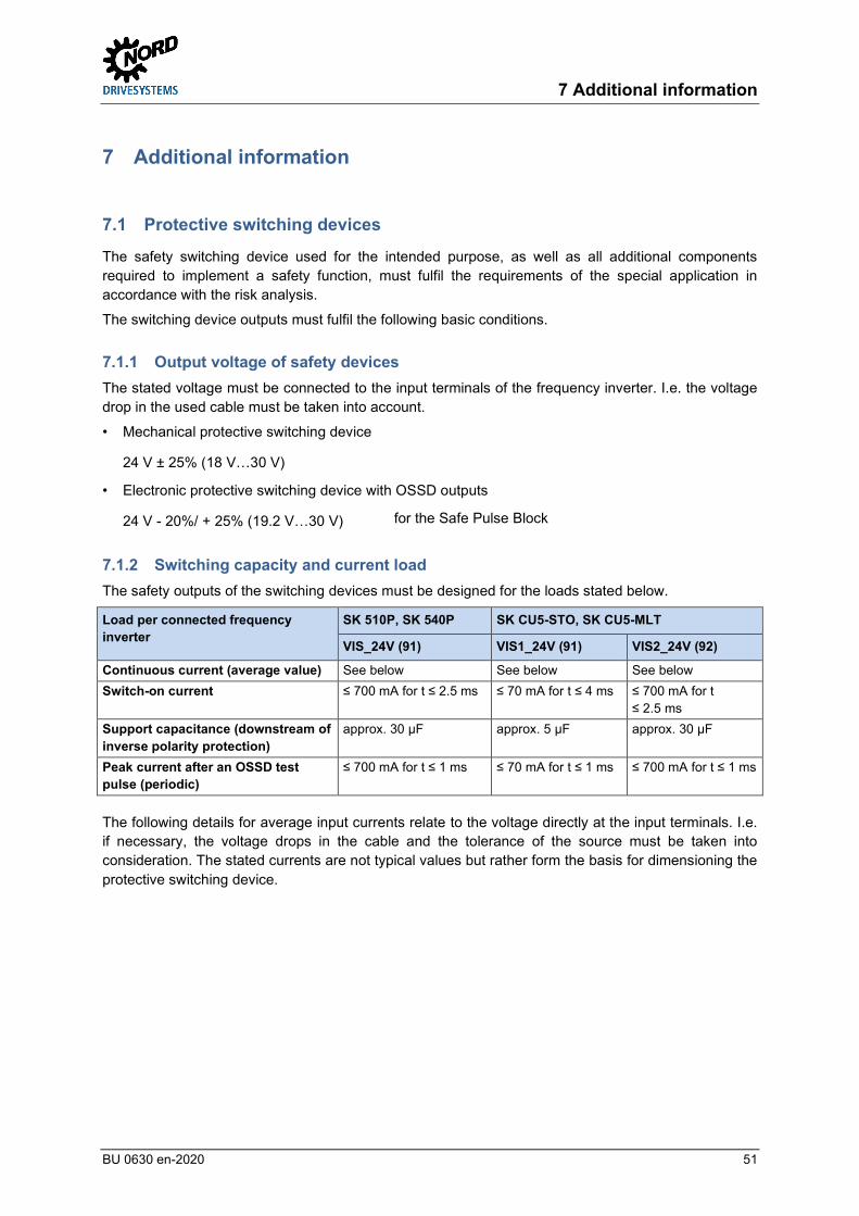
7 Additional information
BU 0630 en-2020 51
7 Additional information Pos: 312 /Anleitungen/El ektr onik /Safety /8. Zusatzinform ati onen/6. Sicherheitsschaltger äte/!Sicher heitsschaltg eräte_01 (Ü berschrift) @ 15\mod_1486125780898_388.docx @ 2318684 @ 2 @ 1
7.1 Protective switching devices Pos: 313 /Anleitungen/El ektr onik /Safety /8. Zusatzinform ati onen/6. Sicherheitsschaltger äte/!Sicher heitsschaltg eräte_02 @ 15\mod_1486125933007_388.docx @ 2318720 @ @ 1
The safety switching device used for the intended purpose, as well as all additional components required to implement a safety function, must fulfil the requirements of the special application in accordance with the risk analysis.
The switching device outputs must fulfil the following basic conditions. Pos: 314 /Anleitungen/El ektr onik /Safety /8. Zusatzinform ati onen/6. Sicherheitsschaltger äte/Ausg angsspannung_01 @ 44\m od_1594888830651_388.docx @ 2646645 @ 3 @ 1
7.1.1 Output voltage of safety devices The stated voltage must be connected to the input terminals of the frequency inverter. I.e. the voltage drop in the used cable must be taken into account.
• Mechanical protective switching device
24 V ± 25% (18 V…30 V)
• Electronic protective switching device with OSSD outputs
24 V - 20%/ + 25% (19.2 V…30 V) for the Safe Pulse Block Pos: 319 /Anleitungen/El ektr onik /Safety /8. Zusatzinform ati onen/6. Sicherheitsschaltger äte/Schaltvermög en und Strom bel astung A bis C [SK 500P] @ 44\mod_1594805164780_388.docx @ 2646413 @ 3 @ 1
7.1.2 Switching capacity and current load The safety outputs of the switching devices must be designed for the loads stated below.
Load per connected frequency inverter
SK 510P, SK 540P SK CU5-STO, SK CU5-MLT
VIS_24V (91) VIS1_24V (91) VIS2_24V (92)
Continuous current (average value) See below See below See below Switch-on current ≤ 700 mA for t ≤ 2.5 ms ≤ 70 mA for t ≤ 4 ms ≤ 700 mA for t
≤ 2.5 ms Support capacitance (downstream of inverse polarity protection)
approx. 30 μF approx. 5 μF approx. 30 μF
Peak current after an OSSD test pulse (periodic)
≤ 700 mA for t ≤ 1 ms ≤ 70 mA for t ≤ 1 ms ≤ 700 mA for t ≤ 1 ms
The following details for average input currents relate to the voltage directly at the input terminals. I.e. if necessary, the voltage drops in the cable and the tolerance of the source must be taken into consideration. The stated currents are not typical values but rather form the basis for dimensioning the protective switching device.

Functional Safety – Supplementary manual for series SK 500P
52 BU 0630 en-2020
Average input current For SK 510P, SK 540P:
Application class Input voltage VIS_24V (91): 18 V 20 V 22 V 24 V 26 V 28 V 30 V
AA 75 mA 69 mA 64 mA 61 mA 58 mA 55 mA 54 mA A 95 mA 86 mA 80 mA 75 mA 71 mA 67 mA 65 mA B 114 mA 104 mA 94 mA 87 mA 82 mA 78 mA 75 mA C 135 mA 123 mA 113 mA 104 mA 97 mA 92 mA 87 mA
Average input current For SK CU5-STO, SK CU5-MLT:
Application class Input voltage VIS1_24V (91): 18 V 20 V 22 V 24 V 26 V 28 V 30 V
All 20 mA 21 mA 22 mA 24 mA 25 mA 26 mA 28 mA Application class Input voltage VIS2_24V (92):
18 V 20 V 22 V 24 V 26 V 28 V 30 V AA 81 mA 78 mA 76 mA 75 mA 74 mA 74 mA 75 mA A 99 mA 94 mA 91 mA 88 mA 87 mA 86 mA 85 mA B 118 mA 111 mA 105 mA 101 mA 98 mA 96 mA 95 mA C 140 mA 131 mA 124 mA 119 mA 115 mA 112 mA 110 mA
Information Increased current on switch-on or after a test pulse from an OSSD Due to the support capacitors of the safe shut-down method, there is an increased current consumption on switch-on and after a test pulse from an OSSD. The Safe Pulse Block is equipped with an active current limiter in order to reduce the load on safety outputs to a minimum. Pos: 321 /Allgem ein/Allgem eingültig e Module/---------Seitenumbr uch kompakt --------- @ 13\m od_1476369695906_0.docx @ 2265495 @ @ 1

7 Additional information
BU 0630 en-2020 53
Pos: 323 /Anleitungen/El ektr onik /Safety /8. Zusatzinform ati onen/6. Sicherheitsschaltger äte/OSSD-Ausgänge, Tes tpulse [SK 500P] @ 40\m od_1578901672922_388.docx @ 2582790 @ 3 @ 1
7.1.3 OSSD outputs, test pulses The OSSD signal must satisfy the following requirements:
• D ≥ 90 % (duty, switch-on ratio) The supply voltage is applied for at least 90% of the time Example: After a test pulse with duration tOSSD the supply voltage is connected for at least 9*tOSSD.
• Double pulses are permissible if the two pulses are at least 2 * tOSSD apart and the condition for D is fulfilled.
Permissible test pulses for an OSSD
Example 1. First test pulse with width tOSSD. 2. The supply voltage is present for at least 1 * tOSSD. 3. Second test pulse with width tOSSD. 4. The supply voltage is present for at least 17 * tOSSD.
• The width of the test pulse should be within the range 0.2 ms ≤ tOSSD ≤ 0.5 ms. The maximum width of the test pulse depends on the application class:
Application class AA, A, B C tOSSD,max 1 ms 0.85 ms
Depending on the application class and the length of the test pulse, it may be necessary to increase the minimum input voltage VIS_24V,min.
Voltage correction of long OSSD test pulses
This voltage correction is cumulative with other corrections.
Voltage correction of long OSSD test pulses

Functional Safety – Supplementary manual for series SK 500P
54 BU 0630 en-2020
Example In the section “Example of multiple device operation”, a minimum input voltage of 𝑉𝑉𝐹𝐹𝐼𝐼_24𝑉𝑉,𝑚𝑚𝑤𝑤𝑚𝑚21.1 𝑉𝑉 was determined for the example of application class B. If in this example, the width of the test pulse is tOSSD = 0.85 ms the minimum input voltage is increased by a further 1.0 V to 𝑉𝑉𝐹𝐹𝐼𝐼_24𝑉𝑉,𝑚𝑚𝑤𝑤𝑚𝑚22.1 𝑉𝑉. If in this example a 24 V voltage source with a tolerance of 10 % is used (VQ,min = 21.6 V), this would be too small, i.e. a source with a smaller tolerance, a shorter test pulse width to the OSSD, or a larger cable cross-section are required. Pos: 324 /Allgem ein/Allgem eingültig e Module/---------Seitenumbr uch kompakt --------- @ 13\m od_1476369695906_0.docx @ 2265495 @ @ 1 Pos : 325 /Anleitungen/El ektr onik /Safety /8. Zusatzinform ati onen/7. Sicherheitseinstufungen/!Sicherheitseinstufungen @ 15\m od_1485524952598_388.docx @ 2317090 @ 2 @ 1
7.2 Safety categories Pos: 327 /Anleitungen/El ektr onik /Safety /8. Zusatzinform ati onen/7. Sicherheitseinstufungen/IEC 60204-1:2016 @ 44\mod_1594804675848_388.docx @ 2646337 @ 3 @ 1
7.2.1 IEC 60204-1:2016 (German version EN 60204-1:2018)
The requirements of category 0 and category 1 stop functions can be fulfilled by the Safe Pulse Block.
Controlled stopping of a category 1 stop function is not fail-safe via the standard functions of the frequency inverter. The switch-over to the category 0 stop function is fail-safe. Pos: 329 /Anleitungen/El ektr onik /Safety /8. Zusatzinform ati onen/7. Sicherheitseinstufungen/61800-5-2:2016 @ 44\mod_1594804770366_388.docx @ 2646375 @ 3 @ 1
7.2.2 IEC 61800-5-2:2016 (German version EN 61800-5-2:2017)
The requirements for the Safe Torque Off (STO) function and the safety integrity level SIL 3 can be fulfilled with the safe shut-down method Safe Pulse Block.
The requirements for the “Safe Stop 1 time-controlled” (SS1-t) function and the safety integrity level SIL 2 can be met with the combination of Safe Pulse Block and Safety Digital Input.
With the SS1-t function, there is no safe monitoring of motor speed reduction or motor speed by the frequency inverter. If a risk analysis shows that monitoring is necessary, this must be performed by an external safety control unit. The solution for the SS1-t function described in the examples corresponds to characteristics as per IEC 61800-5-2:2016, Section 4.2.3.3, Paragraph c) “Triggering of motor speed reduction and triggering of the STO function after an application-specific time delay". The motor speed reduction is carried out via the standard functionality of the frequency inverter and is not fail-safe. Switchover to the STO function is carried out as fail-safe via an external safety control unit, e.g. a protective switching device.
I.e. triggering of the motor speed reduction via the Safety Digital Input can meet the safety integrity level SIL 2. The externally performed transition to the STO function can meet the safety integrity level SIL3.
NOTE: Controlled stopping by the SS1-t function can fail without detection. Because of this, the SS1-t function cannot be used if such failure could cause a hazardous situation in the end application.
The fault response function of the Safety Digital Input is the STO function. If a fault is detected in the Safety Digital Input during motor speed reduction, the motor outputs are switched off by the software. This behaviour corresponds to the STO function. Pos: 333 /Anleitungen/El ektr onik /Safety /8. Zusatzinform ati onen/7. Sicherheitseinstufungen/IEC 61508:2010_01 [SK 500P] @ 44\m od_1594804552539_388.docx @ 2646299 @ 3 @ 1
7.2.3 IEC 61508:2010 (German version EN 61508:2010)
The shut-down method Safe Pulse Block for implementing the STO safety function meets the requirements for safety level SIL 3. The Safety Digital Input for triggering motor braking for the function SS1-t meets the requirements for safety level SIL 2 (see 7.2.2 "IEC 61800-5-2:2016") Pos: 336 /Allgem ein/Allgem eingültig e Module/---------Seitenumbr uch kompakt --------- @ 13\m od_1476369695906_0.docx @ 2265495 @ @ 1

7 Additional information
BU 0630 en-2020 55
Pos: 340 /Anleitungen/El ektr onik /Safety /8. Zusatzinform ati onen/7. Sicherheitseinstufungen/ISO 13849- 1:2015_01 [SK 500P] @ 44\mod_1594804327625_388.docx @ 2646261 @ 3 @ 1
7.2.4 ISO 13849-1:2015 (German version EN ISO 13849-1:2016) The shut-down method Safe Pulse Block for implementation of the STO safety function meets the requirements of Performance Level e and category 4.
The Safety Digital Input for triggering motor braking for the SS1-t function meets the requirements of Performance Level d and category 2. Pos: 345 /Anleitungen/El ektr onik /Safety /8. Zusatzinform ati onen/7. Sicherheitseinstufungen/ISO 13849- 1:2015_07 (INFORM ATION- Bew ertung der Sicher heitsfunk tion) @ 44\m od_1594211871618_388.docx @ 2643864 @ @ 1
Information Evaluation of safety function The values stated in the technical data only refer to the stated inputs or shut-down methods.
The components which are additionally required for the implementation of a safety function, such as protective switching device, emergency stop button, etc. must also be taken into account for the evaluation of the safety function. The resulting safety-relevant data can be significantly influenced by these components.
Pos: 347 /Anleitungen/El ektr onik /Safety /10. Technische Daten/Technische D aten_01 @ 15\mod_1485524804221_388.docx @ 2317054 @ 1 @ 1

Functional Safety – Supplementary manual for series SK 500P
56 BU 0630 en-2020
8 Technical Data Pos: 348 /Anleitungen/El ektr onik /Safety /10. Technische Daten/Technische D aten_02 @ 17\mod_1488804807584_388.docx @ 2333179 @ @ 1
The Technical Data from the frequency inverter manual (BU 0600) apply!
In deviation from this:
Function Specification
Max. installation altitude above sea level
≤ 2000 m
The following technical data also apply. Pos: 349 /Allgem ein/Allgem eingültig e Module/---------Seitenumbr uch kompakt --------- @ 13\m od_1476369695906_0.docx @ 2265495 @ @ 1 Pos : 353 /Technische Inform ati onen/Sonstige Dokum ente/TI 80_0030 - Funktionale Sicher heit NORD AC PRO SK 5xxP/Technische Daten: Sicher e Pulssperre und safety Digital eing ang @ 44\mod_1594131305701_388.docx @ 2643656 @ 2 @ 1
8.1 Safe Pulse Block and Safety Digital Input Safe Pulse Block Safety Digital Input
SK 510P, SK 540P SK CU5-STO or SK CU5-MLT
(SK 530P, SK 550P)
SK 510P and SK 540P, SK CU5-STO or SK CU5-
MLT (530P, SK550P)
Input voltage +24 V ±25% (18 V … 30 V) +24 V -37.5% +25% (15 V … 30 V)
Operation with OSSD -20% … +25% (19.2 V … 30 V) +24 V -37.5% +25% (15 V … 30 V)
High - level (VT+) ≥ 18 V ≥ 15 V Low - level (VT-) ≥ 3 V ≥ 3 V Current consumption (average value)
Depending on the input voltage and application class (inverter type and pulse frequency) see 7.1.2 "Switching capacity
and current load"
≤ 10 mA
Peak current (peak, when switching on or on the OSSD)
≤ 700 mA VIS1: ≤ 70 mA VIS2: ≤ 700 mA
≤ 25 mA
Input resistance – – Low level: 10 kΩ High level: 3 … 5 kΩ
Input capacitance approx. 30 µF (downstream of inverse polarity
protection)
VIS1: approx. 5 µF VIS2: approx. 30 µF
(downstream of inverse polarity
protection)
approx. 10 nF
Cable length ≤100 m (shielded for compliance with EMC requirements), see 3.3.3 "EMC"
Cable capacitance ≤ 20 nF per connected frequency inverter (≤ 4 nF * tOSSD/ 0,1 ms for tOSSD ≤ 500 µs)
Requirements for OSSDs Test pulse width 200 µs ≤ tOSSD ≤ 500 μs, see 3.3.2 "Operation with OSSD" Duty (High level) ≥ 90 %
Time between double pulses ≥ 2 * tOSSD (note the duty factor) Switch-on delay (time between input change from Low to High level and the time at which enabling of the frequency inverter is possible.)
≤ 160 ms ≤ 25 ms ≤ 15 ms

8 Technical Data
BU 0630 en-2020 57
Response time (time between input change from High to Low level and triggering of the safety sub-function.)
≤ 130 ms ≤ 140 ms ≤ 10 ms
Cycle time (time between two identical flanks at the input)
≥ 1 s
Fault response time (The time between detection of a fault and triggering of the fault response function.)
– ≤ 35 ms
Fault response function – Inverter shut-down (behaviour as for STO)
Priority Highest Low
Source of failure rates SN 29500 at ambient temperature: 40°C (S1 operation) or 50°C (S3 operation with ED = 70%) Special device SK 5x0P-751-340-S3: 40°C (S3 operation with ED = 70%) or 50°C (S3 operation with ED = 50%)
Conformant object Type B Hardware error tolerance HFT 0 Proportion of safe failures SFF = 100% SFF = 97.89% Probability of a hazardous failure per hour
PFH = 0 PFH = 11.33 FIT
Mean time until hazardous failure MTTFd = "High" (> 100 years) Diagnostic coverage level cannot be determined (PFH = 0) DC = 92.85% (“average”) Safety integrity level (as per IEC 61800-5-2:2016 and IEC 61508:2010)
SIL 3 SIL 2
Category (as per EN ISO 13849-1:2016)
Category 4 Category 2
Performance Level (as per EN ISO 13849-1:2016)
PL e PL d
Proof Test Interval TM = 20 years (duration of use, “Mission Time”)
Pos: 354 /Allgem ein/Allgem eingültig e Module/---------Seitenumbr uch kompakt --------- @ 13\m od_1476369695906_0.docx @ 2265495 @ @ 1 Pos : 361 /Anleitungen/El ektr onik /Bussysteme/Alle Baureihen/9. ( 7.) Anhang/!Kapitel Anhang @ 8\m od_1444048184081_388.docx @ 2237632 @ 1 @ 1

Functional Safety – Supplementary manual for series SK 500P
58 BU 0630 en-2020
9 Appendix Pos: 362 /Anleitungen/El ektr onik /Safety /11. Anhang/Wartungshinw eise @ 16\m od_1488441976364_388.docx @ 2331139 @ 2 @ 1
9.1 Maintenance information The maintenance information from the frequency inverter manual (BU 0600) apply.
The information on long-term storage also apply for the Safe Pulse Block.
Thus, the Pulse Block must be supplied with a voltage of 24 V DC at least 1 x per year for 60 minutes in order to maintain its function and to prevent damage to the Safe Pulse Block. Pos: 363 /Anleitungen/El ektr onik /Bussysteme/Alle Baureihen/9. ( 7.) Anhang/R eparatur hinw eise @ 42\m od_1589956872993_388.docx @ 2612990 @ 2 @ 1
9.2 Repair information In order to keep repair times as short as possible, please state the reason for returning the device and at least one contact in case of queries.
In case of repair, please send the device to the following address:
NORD Electronic DRIVESYSTEMS GmbH Tjüchkampstraße 37
26606 Aurich
Information Third party accessories Getriebebau NORD GmbH & Co. KG cannot accept liability for third party accessories if these are returned with the device.
Information Accompanying document Please complete the accompanying document for the return. This can be found on our homepage www.nord.com or directly under the link Warenbegleitschein
In case of queries about repairs please contact:
Getriebebau NORD GmbH & Co. KG Tel.: +49 (0) 45 32/ 289-2515
Fax: +49 (0) 45 32 / 289-2555 Pos: 364 /Allgem ein/Allgem eingültig e Module/---------Seitenumbr uch kompakt --------- @ 13\m od_1476369695906_0.docx @ 2265495 @ @ 1

9 Appendix
BU 0630 en-2020 59
Pos: 365 /Anleitungen/El ektr onik /Bussysteme/Alle Baureihen/9. ( 7.) Anhang/Service- und Inbetriebnahmehinw eise [BU 2100 . .. BU 2800, Safety, POSIC ON, PlC, CTT2] @ 32\m od_1553246313738_388.docx @ 2518584 @ 2 @ 1
9.3 Service and commissioning information In case of problems, e.g. during commissioning, please contact our Service department:
+49 4532 289-2125
Our Service department is available 24/7 and can help you best if you have the following information about the device and its accessories to hand:
• Type designation, • Serial number, • Firmware version Pos: 369 /Anleitungen/El ektr onik /Safety /11. Anhang/Dokum entation und Softw are [Safety : SK 5xxP] @ 38\m od_1569832099629_388.docx @ 2562100 @ 2 @ 1
9.4 Documents and software Documents and software can be downloaded from our website www.nord.com.
Other applicable documents and further information
Documentation Contents
BU 0600 Manual for frequency inverter NORDAC PRO (SK 500P) BU 0000 Manual for use of NORDCON software BU 0040 Manual for use of NORD ParameterBoxes
Software
Software Description
NORDCON Parameterisation and diagnostic software
Pos: 373 /Anleitungen/El ektr onik /Safety /11. Anhang/Zerti fikate [Safety: SK 5xxP] @ 40\m od_1582036792569_388.docx @ 2590906 @ 2 @ 1
9.5 Certificates The relevant certificates for Functional Safety can be downloaded from our internet page www.nord.com.
Certificates
Documentation Contents
C330602 Certificate for frequency inverters with "Safe Shut-down Methods“– NORDAC for frequency inverters NORDAC PRO SK 500P
Pos: 374 /Allgem ein/Allgem eingültig e Module/---------Seitenumbr uch kompakt --------- @ 13\m od_1476369695906_0.docx @ 2265495 @ @ 1

Functional Safety – Supplementary manual for series SK 500P
60 BU 0630 en-2020
Pos: 375 /Anleitungen/El ektr onik /Safety /11. Anhang/Abkürzungen @ 16\m od_1487168269925_388.docx @ 2327336 @ 2 @ 1
9.6 Abbreviations
• AS-i AS-Interface • BW Braking resistor • DIN Digital input • DOUT Digital output • EMC Electromagnetic compatibility • FI Frequency inverter • GND Ground • OSSD Output Signal Switching Device • P Parameter set dependent parameter, i.e. a parameter which can be assigned different
functions or values in each of the 4 parameter sets of the frequency inverter. • PDS(SR) Power Drive Systems (Safety Related) → Power drive systems with integrated safety
functions. • S Supervisor parameter, i.e. a parameter which is only visible if the correct Supervisor
Code is entered in parameter P003 • SH Safe Stop (functional safety) • SS1 Safe Stop 1 • STO Safe Torque Off, torque safely switched off • SW Frequency inverter software or firmware version (“Software Version” (P707)) === Ende der Liste für Textm arke Inhalt ===

Key word index
BU 0630 en-2020 61
Pos: 377 /Allgem ein/Steuerm odule/Stichw ortverzeichnis @ 0\mod_1317978518730_388.docx @ 4101 @ @ 1
Key word index === Ende der Liste für Textm arke Stichw ortverzeichnis ===
A
Accompanying document .............................. 58
Auto. Fault acknowledgement (P506) ........... 47
Automatic start (P428) ................................... 44
C
Certificates ..................................................... 59
Commissioning .............................................. 36
SS1-t .......................................................... 37
STO ............................................................ 36
D
DC run-on time (P559) .................................. 47
Digital out function (P434) ............................. 45
Documents
Other applicable ......................................... 59
E
EMC ............................................................... 35
Example ......................................................... 34
SS1-t .......................................................... 19
STO ............................................................ 15
Exclusion of faults .......................................... 25
F
Function BusIO Out Bits (P481) .................... 45
I
IEC 60204-1
2018 ........................................................... 54
IEC 61508
2010 ........................................................... 54
IEC 61800-5-2
2017 ........................................................... 54
M
Mechanical brake .......................................... 14
Messages
Fault ........................................................... 48
Operating state .......................................... 48
O
OSSD ............................................................. 51
P
Parameterisation of the safe digital input...... 41
Parameters ................................................... 41
Protective switching devices ......................... 51
Q
Quick stop time (P426) ................................. 44
R
Repairs .......................................................... 58
Re-start block ................................................ 21
Returns ......................................................... 58
S
Safe Dig.input (P424).................................... 43
Safe Pulse Block ........................................... 32
Example .................................................... 34
Safe shut-down method
Safe Pulse Block ....................................... 32
Safety CRC (P499) ....................................... 46
Safety functions
Safe torque switch-off................................ 14
STO ........................................................... 14
Safety Password (P497) ............................... 45
Safety Password (P498) ............................... 45
Safety SS1 max. time (P423) ....................... 43
Software ........................................................ 59
SS1-t
Commissioning .......................................... 37
Example .................................................... 19
Standard
IEC 60204-1
2016 ....................................................... 54
IEC 61508
2010 ....................................................... 54
IEC 61800-5-2
2016 ....................................................... 54
STO ............................................................... 14
Commissioning .......................................... 36
Example .................................................... 15

Functional Safety – Supplementary manual for series SK 500P
62 BU 0630 en-2020
T
Technical Data ............................................... 56
V
Validation ...................................................... 40

Key word index
BU 0630 en-2020 63

607
6302
/ 20
20