full document approved by the transit office florida
TRANSCRIPT
CRASH AND SAFETY TESTING STANDARD
FOR PARATRANSIT BUSES ACQUIRED BY THE STATE OF FLORIDA
FULL DOCUMENT
Approved by the Transit Office
Florida Department of Transportation
Prepared by:
Crashworthiness and Impact Analysis Laboratory
FAMU-FSU College of Engineering
2525 Pottsdamer Street
Tallahassee, FL 32310-6046
http://www.eng.fsu.edu/~wekezer
Revision 3.01 November 1, 2009
Crash and Safety Testing Standard page 1
CRASH AND SAFETY TESTING STANDARD
FOR PARATRANSIT BUSES ACQUIRED BY THE STATE OF FLORIDA
CONTENTS
Page
1. Scope .................................................................................................................................... 2
2. Terms and definitions ........................................................................................................... 2
3. Approval ............................................................................................................................... 4
3.1. Approval methods .................................................................................................... 4
3.2. Partial validation requirements ................................................................................. 4
3.3. Impact scenarios ....................................................................................................... 4
3.4. Full-scale crash tests ................................................................................................. 5
4. Crashworthiness assessment through full-scale experiments ................................................ 5
4.1. Requirements ............................................................................................................ 5
5. Finite element model development ...................................................................................... 5
5.1. Input data .................................................................................................................. 5
5.2. FE model requirements ............................................................................................. 6
6. Verification and validation of FE models ............................................................................ 6
6.1. Verification and validation ....................................................................................... 6
6.2. New vehicle types and updated models .................................................................... 6
6.3. Material characterization tests for major structural parts of the body ...................... 6
6.4. Quasi-static connection tests .................................................................................... 7
6.5. Impact hammer test of a bus wall panel ................................................................... 7
6.6. Verification of center of gravity, mass and wheel reactions .................................... 7
6.7. Verification of energy ............................................................................................... 7
7. Crashworthiness assessment through computer simulations ................................................ 7
7.1. Computational mechanics methodology .................................................................. 7
7.2. Side impact simulation ............................................................................................. 8
7.3. Roll-over simulation ................................................................................................. 8
8. Disclaimer ............................................................................................................................. 8
APPENDICES
Appendix 1- Residual space ........................................................................................................... 10
Appendix 2- Material testing of major structural parts of the bus body ......................................... 12
Appendix 3- Quasi-static tests of roof-to-wall and wall-to-floor connections ................................ 13
Appendix 4- Impact hammer test of a bus side wall panel .............................................................. 15
Appendix 5- Center of gravity of the vehicle .................................................................................. 18
Appendix 6- Side impact test ......................................................................................................... 22
Appendix 7- Roll-over test .............................................................................................................. 23
Appendix 8- Pre-approval ............................................................................................................... 24
REFERENCES ................................................................................................................................ 25

Crash and Safety Testing Standard page 2
1. SCOPE
This Standard applies to single-deck vehicles designed and constructed for more than 8 but
less than 22 passengers, whether seated or standing, in addition to the driver and crew. It
describes the testing procedures required to assess crashworthiness and safety of
paratransit buses in the State of Florida. They are extracted from, and are consistent with
all current bus safety standards as required by the U.S., U.N., and E.U. regulations. Either
full scale experimental crash tests or computational mechanics finite element methods
(FE) shall be used for this assessment. Full scale crash tests include a side impact test and
a rollover test. Satisfactory performance of the paratransit buses during actual or simulated
side impact and rollover tests is required for their approval. Several laboratory tests are
required for validation of the FE models for simulation-based approvals. An
uncompromised residual space concept is adopted in this standard as a pass/fail criterion.
2. TERMS AND DEFINITIONS
For the purposes of this Standard, the following units and definitions are used [1]:
2.1. Units. SI and U.S. Customary unit systems can be used for experimental tests and in situ
measurements. Results can be presented in SI and U.S. Customary. The Finite Element
calculations shall be carried using one consistent SI system with mm, s, t (tone) as basic
units. The units for FE calculations are provided in Table 2.1.1.
Table 2.1.1. The units for FE calculation
Dimensions and linear distances millimeters (mm)
Mass tone (t)
Force (and weight) Newtons (N)
Stress Mega Pascal (MPa)
Energy milli Joules (mJ)
Gravitational constant 9,810 ( mm/s2)
2.2. "Vehicle" means a bus or coach designed and equipped for transportation of passengers.
The vehicle is an individual representative of a vehicle type.
2.3. "Vehicle type" means a category of vehicles produced with the same design technical
specification, main dimensions and structural arrangement. The vehicle type shall be
defined by the vehicle manufacturer.
2.4. "Family of vehicle types" means those vehicle types, proposed in future as well as
currently existing, which are covered by the approval of the worst case, in accordance with
this Standard.
2.5. "Worst case" means the vehicle type, among a group of vehicle types, least likely to
withstand the requirements of this Standard with respect to the strength of the
superstructure.
2.6. "Approval of a vehicle type" means an official process in which the vehicle type is
checked and tested to prove that it meets all the requirements specified in this Standard.

Crash and Safety Testing Standard page 3
2.7. "Passenger compartment" means the space intended for passengers' use, excluding any
space occupied by additional fixed equipment such as wheelchair lifts.
2.8. "Driver's compartment" means the space intended for the driver's exclusive use and
containing the driver's seat, the steering wheel, controls, instruments and other devices
necessary for driving the vehicle.
2.9. "Occupant restraint" means any device which connects a passenger, a driver or a crew
member to his/her seat.
2.10. "Residual space" means a space to be preserved in the passengers', crew and driver's
compartment(s) to provide safe environment for the passengers, the driver and the crew in
case of an accident.
2.11. "Unloaded curb mass" (Mk) means the mass of the vehicle in running order, unoccupied
and unloaded but with the addition of 75 kg for the mass of the driver, the mass of fuel
corresponding to 90 percent of the capacity of the fuel tank specified by the manufacturer,
and the mass of coolant, lubricant, tools and spare wheel, if any.
2.12. "Reference energy" (ER) means the potential energy of the vehicle type to be approved,
measured from the starting, unstable position CG‟ to the CG” position when the roof-to-
wall edge of the bus touches the concrete bottom of the ditch (Figure A7.1).
2.13. "Rollover test on a complete vehicle" means a test on a complete, full-scale vehicle to
prove the required strength of the superstructure.
2.14. "Tilting platform" means a rigid stand which can be rotated around a horizontal axis in
order to perform a rollover test on a complete vehicle.
2.15. "Body work" means a complete structure of the vehicle in running order, including all
structural elements which form the passenger compartment, driver's compartment,
baggage compartment and spaces for the mechanical units and components.
2.16. "Superstructure" means the load-bearing components of the bodywork as defined by the
manufacturer, containing those coherent parts and elements which contribute to the
strength and energy absorbing capability of the bodywork, and which preserve the residual
space in the rollover test.
2.17. “Energy balance" means checking the principle of energy conservation during the standard
side impact or the rollover test. The total potential energy of the vehicle is transformed
through its kinetic energy into other forms of energy.
2.18. "Plastic zone" (PZ) means a special, geometrically limited part of the superstructure
produced by dynamic impact forces. Plastic zones are characterized by:
o large scale, concentrated plastic deformations,
o significant distortion of the original shape (cross section, length, or other geometry),
o loss of stability resulting from local buckling, and
o kinetic energy transformed into internal energy.

Crash and Safety Testing Standard page 4
2.19. "Cantrail" means the longitudinal structural part of the bodywork above the side windows
including the curved transition to the roof structures. The cantrail hits the ground first
during the rollover test.
2.20. Finite Element (FE) analysis means non-linear, explicit, computational mechanics study
used to assess crashworthiness of the bus and to predict its dynamic, structural response
during accidents.
2.21. Side impact test means an experimental collision of a SUV or a pickup truck crashing into
the driver side of a paratransit bus. The impacted bus shall be stationary at the time of the
impact. The test setup is described by such parameters as velocity of the impacting vehicle
(SUV), its mass, dimensions of its frontal bumper, an impact angle, and a location of the
impacted zone.
2.22. Crashworthiness means the bus ability to provide passive safety for the passengers through
dissipation of the vehicle kinetic energy during crash accidents. Crashworthiness is
achieved through a balanced design with some elements which promote the development
of the plastic zones for efficient energy transfer, and with other structural elements which
help to preserve the passenger residual space.
3. APPROVAL
3.1. Approval methods. Crashworthiness and safety of the paratransit bus shall be assessed by
either:
o Experimental, full-scale crash tests, or
o Numerical analysis using a FE method.
Both methods are considered equivalent and either one may be selected by the bus
manufacturer for the bus approval, as shown in Figure 1. The paratransit bus is considered
to be crashworthy and safe if its residual space (as defined in Appendix 1) is neither
compromised through intrusion (Section 5.3.1) nor by projection (Section 5.3.2).
3.2. Partial validation requirements. Numerical analysis using a FE method requires a reliable
and validated FE model. A model validation process, as shown in Figure 1, shall be based
on the following laboratory tests:
o Material characterization tests of major structural parts of the body bus (Appendix 2),
o Quasi-static tests of roof-to-wall and wall-to-floor connections (Appendix 3),
o Impact hammer test of a bus side wall panel (Appendix 4), and
o Center of gravity test of the vehicle (Appendix 5).
3.3. Impact scenarios. The validated FE model shall be used to assess crashworthiness and
safety of the bus through:
o Side impact test (Appendix 6), and
o Roll over test (Appendix 7).
Successful performance of both tests is required for the approval of the paratransit bus.

Crash and Safety Testing Standard page 5
Figure 1. Approval methods for paratransit buses.
3.4. Full-scale crash tests. The experimental full-scale crash test becomes mandatory if the
paratransit bus fails either of the computational analysis tests, as listed in Section 3.2.
4. CRASHWORTHINESS ASSESSMENT THROUGH FULL-SCALE EXPERIMENTS
4.1. Requirements. Two full scale tests shell be performed under this option: a rollover test and
a side impact tests. Requirements for both tests are included in Appendices 6 and 7.
5. FINITE ELEMENT MODEL DEVELOPMENT
5.1. Input data. All data and information which are needed to evaluate the worst case criteria in
a group of vehicle types are required. The following AutoCAD files or their hard copies
shall be provided by the manufacturer:
o General layout drawings of the vehicle, its bodywork and its interior arrangement with the
main dimensions. Seats shall be clearly marked and their positions in the vehicle shall be
accurately dimensioned.
o Drawings and detailed description of the superstructure of the vehicle type or group of
vehicle types.
o Thicknesses of the structural components.
o Material identification, its properties, and steel grades.
Crash and Safety Testing Standard page 6
o If requested, the manufacturer shall answer questions and allow for visual checking of
details regarding connections between body structure elements and the methods of
construction.
o The unloaded curb mass of the vehicle, and the associated axle loads.
5.2. FE model requirements. The FE model shall be capable of describing a real physical
behavior of the actual vehicle subjected to the loadings and conditions present during the
tests. The FE model shall be developed based on assumptions which shall produce
conservative results. The model shall be developed within the following guidelines:
5.2.1. The tests required shall be carried out on the actual vehicle structural elements to prove the
validity of the mathematical model and to verify the assumptions made in the model.
5.2.2 The total mass and the center of gravity position used in the FE model shall be equal to
those of the vehicle to be approved. A discrepancy of up to ± 2% in each is allowed.
5.2.3. The mass distribution in the FE model shall correspond to the vehicle to be approved.
Moments of inertia used in the FE model shall be calculated based on this mass
distribution.
5.2.4. The F.E. program may start at the moment just prior to the first contact with the
bottom of the ditch with the appropriate initial conditions.
5.2.5. The F.E. program shall run until the maximum deformation of the bus is reached.
5.2.6. The F.E. program shall produce a stable solution, in which the result is neither dependent
on the incremental time step nor on the F.E. grid density of the model.
5.2.7. The coefficient of friction used at the ground contact shall shell be carefully selected to
produce conservative results. Physical tests shall be considered if appropriate.
5.2.8. All possible physical contacts between parts of the vehicle shall be identified and
accounted for in the FE model.
6. VERIFICATION AND VALIDATION OF F.E. MODELS
6.1. Verification and validation. Verification is a qualitative process of confirming that a
computer code correctly implements the algorithms that were intended. Validation is a
quantitative process of confirming that computer simulations adequately represent
physical phenomena measured through laboratory or full-scale testing programs.
6.2. New vehicle types and updated models. One full-scale rollover test and one full scale
rollover test shall be required for a FE model validation of a completely new vehicle type.
Due to a high cost of full-scale bus tests, partial FE model validations shall be used when
minor structural modifications are introduced in new bus models, as described in Sections
5.3. through 5.6.
6.3. Material characterization tests for major structural parts of the body. The main goal of the
material testing is to identify actual material properties of the major structural components.
Appendix 2 provides guidelines for coupon testing. Material properties acquired from

Crash and Safety Testing Standard page 7
these tests shall be used in all subsequent elements of the numerical approval process, as
described in Sections 5.4 through 5.6.
6.4. Quasi-static connection tests. Two vulnerable connections of each bus: roof-to-wall, and
wall-to-floor shall be tested for its FE model validation. Each connection shall include all
original structural elements, with the bus skin, but without any additional reinforcements,
which are not present in the actual bus. Crashworthiness of these structural connections is
considered critical during roll-over and side impact accidents. Both quasi-static tests shell
be performed according to guidelines presented in Appendix 3. Experimental data shall be
used for FE model validation for both connections.
6.5. Impact hammer test of a bus wall panel. Vehicle accidents result in significant dynamic
loading applied to the bus structure. Energy transfer: from kinetic into internal, and
between impacting and impacted vehicles, take place in short time intervals (such as 0.1
second). Dynamic material behavior is dependent on the strain rates and is usually
different from its static behavior. Therefore, at least one dynamic test on a side wall panel
of the bus shall be performed to validate the F.E. bus model. Appendix 4 describes details
of the impact hammer test of a panel cut of the body side wall. Comparison of the
experimental results with the computer simulations of the pendulum test shall be used for
F.E. model validation.
6.6. Verification of center of gravity, mass, and wheel reactions. Mass distribution of the FE
model must be compared with actual values from the manufacturer‟s specification, or from
in situ measurements to partially validate the FE model. The comparison shall include the
position of the center of gravity (CG), the unloaded curb mass, and the wheel reactions.
The testing of the CG location for an actual vehicle shall be based on the procedure
described in Appendix 5.
6.7. Verification of energy. The FE computer program shall be able to provide calculations of
energy components for the energy balance at every incremental time step. The energy
balance is a major criterion used for verification of computational mechanics studies. The
total energy shall remain constant with kinetic energy transferred into internal energy.
Non-physical energy components introduced through FE modeling (for example,
"hourglass" and internal damping) shall not exceed 5 percent of the total energy at any
time. Kinetic energy shall be verified through classical hand calculations based on the
trajectory of the CG of the FE model. An additional CG node, rigidly connected to the
floor, shall provide this trajectory data as a direct output.
7. CRASHWORTHINESS ASSESSMENT THROUGH COMPUTER SIMULATIONS
7.1. Computational mechanics methodology. An approval of a new vehicle type with regard to
the strength of its superstructure shall be made through a validated FE analysis based on
the information data and test material acquired from laboratory testing and provided by the
vehicle manufacturer. A description of the computational mechanics method which has
been utilized, precise identification of the analysis software, including its producer, its
commercial name, and the version shall be provided in the final report. The final report
shall also include a list of the material models and the input data utilized. FE simulations
shall include all numerical tests, as described in Appendices 3 through 7. The final
approval of the bus type will be made based on the results of these tests. Both: rollover

Crash and Safety Testing Standard page 8
and side impact full-scale tests on the complete vehicle shall be considered if the
simulation results are not satisfactory.
7.2. Side impact simulation. A side impact is one of the critical performance tests, which shall
be implemented either as a full-scale crash test, or through computational mechanics
analysis. The impacted paratransit bus shall be stationary, while the impacting vehicle
shall approach its target with a velocity of 30 mph at a 90o angle. Details of the side
impact tests are provided in Appendix 6.
7.2.1. Impacting vehicle. Ford Explorer, Chevrolet S10 pickup, and Chevrolet C2500 pickup
trucks shall be used as impacting vehicles. If an alternative vehicle is used, it shall be
selected within the similar mass, bumper height, and location of CG as the primary
vehicles specified in this Section.
7.2.2. Impact point. The bus shall be impacted between the front and the rear axles, on the street
(driver‟s) side. The closest, right end of the impacting bumper shall be located from the
rear bus wheel at a distance of d = 100 mm (Figure A6.1.).
7.2.3. Residual space. The bus shall pass the test if the passenger residual space, as defined in
Appendix 1, is not compromised as a result of the simulated side impact.
7.3. Roll-over simulation. A computational mechanics analysis shall be carried out according
to the test procedure described in Appendix 7. The approval is based on the concept of
preserving the residual space, defined in Appendix 1. The superstructure of the vehicle
shall have the sufficient strength to ensure that the residual space during and after the
rollover test on complete vehicle is uncompromised.
7.3.1. Intrusion. No part of the vehicle located outside the residual space at the start of the test
(e.g. wheelchair lifts, stanchions, safety rings, and luggage racks) shall intrude into the
residual space during the test. Any structural parts, which are originally in the residual
space (e.g. vertical handholds) shall be ignored when evaluating the intrusion into the
residual space.
7.3.2. Projection. No part of the residual space shall project outside the contour of the deformed
structure. The contour of the deformed structure shall be determined sequentially, between
every adjacent window and/or door pillar. The contour between two deformed pillars
shall be established as a theoretical surface, determined by straight lines. It shall connect
inside contour points of the pillars at the same elevation, above the floor level, before the
rollover test.
8. DISCLAIMER
This specification is extracted from, and is consistent with bus safety standards as required by the
referenced U.S., U.N., and E.U. regulations as of the date of release of this Revision.
Neither the Crashworthiness and Impact Analysis Laboratory of the FAMU-FSU College of
Engineering, its faculty, Florida State University, Florida A&M University, and their respective
Boards of Trustees, nor the Florida Department of Transportation make any warranty, express or
implied, as to the accuracy, quality or usefulness of the information contained in this publication
for any purpose. In no event shall FAMU-FSU College of Engineering, Florida State University,

Crash and Safety Testing Standard page 9
Florida A & M University, their respective Boards of Trustees, nor the Florida Department of
Transportation be liable for any direct, indirect, punitive, incidental, special, consequential
damages, or any damages whatsoever arising out of or connected with the use or misuse of this
document. The parties do not warrant that the prescribed tests and calculations are sufficient to
establish the safety or structural integrity of any vehicle in an actual collision.
Crash and Safety Testing Standard page 10
Appendix 1
RESIDUAL SPACE
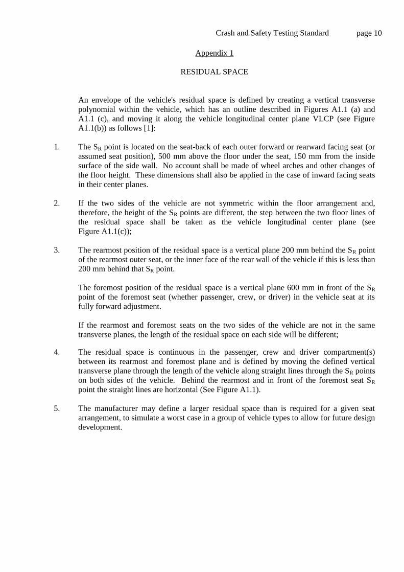
An envelope of the vehicle's residual space is defined by creating a vertical transverse
polynomial within the vehicle, which has an outline described in Figures A1.1 (a) and
A1.1 (c), and moving it along the vehicle longitudinal center plane VLCP (see Figure
A1.1(b)) as follows [1]:
1. The SR point is located on the seat-back of each outer forward or rearward facing seat (or
assumed seat position), 500 mm above the floor under the seat, 150 mm from the inside
surface of the side wall. No account shall be made of wheel arches and other changes of
the floor height. These dimensions shall also be applied in the case of inward facing seats
in their center planes.
2. If the two sides of the vehicle are not symmetric within the floor arrangement and,
therefore, the height of the SR points are different, the step between the two floor lines of
the residual space shall be taken as the vehicle longitudinal center plane (see
Figure A1.1(c));
3. The rearmost position of the residual space is a vertical plane 200 mm behind the SR point
of the rearmost outer seat, or the inner face of the rear wall of the vehicle if this is less than
200 mm behind that SR point.
The foremost position of the residual space is a vertical plane 600 mm in front of the SR
point of the foremost seat (whether passenger, crew, or driver) in the vehicle seat at its
fully forward adjustment.
If the rearmost and foremost seats on the two sides of the vehicle are not in the same
transverse planes, the length of the residual space on each side will be different;
4. The residual space is continuous in the passenger, crew and driver compartment(s)
between its rearmost and foremost plane and is defined by moving the defined vertical
transverse plane through the length of the vehicle along straight lines through the SR points
on both sides of the vehicle. Behind the rearmost and in front of the foremost seat SR
point the straight lines are horizontal (See Figure A1.1).
5. The manufacturer may define a larger residual space than is required for a given seat
arrangement, to simulate a worst case in a group of vehicle types to allow for future design
development.

Crash and Safety Testing Standard page 11
Fig
ure
A1.1
- S
pec
ific
atio
n o
f th
e re
sidual
spac
e [1
],[3
]

Crash and Safety Testing Standard page 12
Appendix 2
MATERIAL TESTING OF MAJOR STRUCTURAL PARTS OF THE BUS BODY
1. At least three sets of specimens cut out of the original bus components such as: body skin
(outer layer), tubes used as the cage elements, and floor panel shall be delivered by the
manufacturer for material testing to determine properties of the materials used for the bus.
2. Samples cut out of the floor plate shall be tested for static four point bending. The
rectangular specimens with the dimensions 4a x 0.5a, where „a‟ is the characteristic
dimension ranging from 4 to 12 in., shall be loaded according to Figure A2.1. The point
load F and a corresponding displacement “d” at the mid-span of beam shall be recorded.
The test shall be conducted until failure.
Figure A2.1 Test setup for four point bending with a=1ft.
3. Material samples extracted from the body skin and from the structural elements shall
undergo the tensile test. These coupons shall be of a rectangular shape with an aspect ratio
(longer side to the smaller side) equal to ten. Precise dimensions must be determined based
on the capabilities of the testing equipment.
4. Each test shall be repeated at least once under the same conditions as the original one.
5. The readings of instantaneous loading and corresponding strain or displacement shall be
acquired simultaneously.
6. Values of recorded loading and strains will be used to determine stress-strain relations
with engineering (nominal) values. They will be converted to real (actual) properties and
will be used as an input in the F.E. model.
7. The main tensile testing shall be conducted as quasi-static with the loading rate smaller
than the maximum specified in the appropriate standard for laboratory testing. The quasi-
static tensile tests shall be repeated with the maximum allowed loading speed resulting in
quasi-dynamic tests. The time for each reading shall be recorded in this case. This quasi-
dynamic data can be used to estimate the strain rate dependence of the material tested.
F
d
½ a ½ a ½ a ½ aa a

Crash and Safety Testing Standard page 13
Appendix 3
QUASI-STATIC TESTS OF ROOF-TO-WALL AND WALL-TO-FLOOR CONNECTIONS
1. Crashworthiness of the bus structure during a side impact or rollover accidents depends on
its roof-to-wall and wall-to-floor connections. The test setup is presented in Figure A3.1.
The width of the roof, floor and wall panels shall be the same and shall include at least two
vertical elements of the steel frame and at least two horizontal steel elements (tubes or C-
channels) in the floor. The wall panel shall be cut at the level just under the window. The
roof and floor width shall be of approximately the same length.
2. The roof or floor panel shall be fixed while the wall panel is loaded horizontally inwards
during the test. The loading shall be applied to the top edge of the wall section. The load
shall be evenly distributed along the entire panel length through a rigid strip as presented
in Figure A3.1.
Figure A3.1 Setup for connection testing. a) Roof-to-wall and wall-to-floor connections,
b) Supports and force application for the wall-to-floor connection.
3. Loading and the resulting displacement along its direction shall be recorded
simultaneously during the test. The load shall be increased gradually, taking measurements
of the associated deformation at discrete intervals until the ultimate deformation is
reached. The resulting resistance function (force vs. displacement, or bending moment vs.
angle of rotation) shall allow identifying plastic zones (PZ), as shown in Figure A3.2, [1].
The frequency of measurement shall allow producing a continuous curve. The "measured
range", the range of deformation over which measurement has been made, shall include
the phase of the plastic deformation and shall reach beyond the point of maximum loading.
Both load and deformation shall be measured to an accuracy of 1 per cent.
Floor panel
Wa
ll p
an
el
b)

Crash and Safety Testing Standard page 14
Figure A3.2 A sample of the resistance function with a plastic hinge, [1].
4. If the applied load changes its direction due to large deformations of the wall panel, the
resulting plastic displacement and an angle at which the force is applied shall be recorded
during the experiment.
Crash and Safety Testing Standard page 15
Appendix 4
IMPACT HAMMER TEST OF A BUS SIDE WALL PANEL
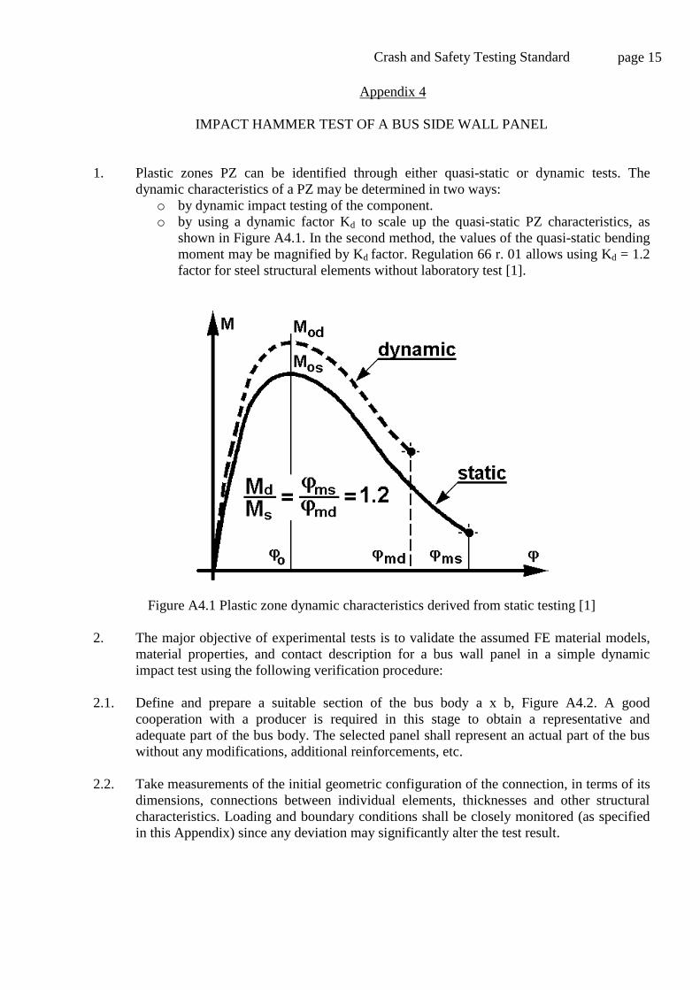
1. Plastic zones PZ can be identified through either quasi-static or dynamic tests. The
dynamic characteristics of a PZ may be determined in two ways:
o by dynamic impact testing of the component.
o by using a dynamic factor Kd to scale up the quasi-static PZ characteristics, as
shown in Figure A4.1. In the second method, the values of the quasi-static bending
moment may be magnified by Kd factor. Regulation 66 r. 01 allows using Kd = 1.2
factor for steel structural elements without laboratory test [1].
Figure A4.1 Plastic zone dynamic characteristics derived from static testing [1]
2. The major objective of experimental tests is to validate the assumed FE material models,
material properties, and contact description for a bus wall panel in a simple dynamic
impact test using the following verification procedure:
2.1. Define and prepare a suitable section of the bus body a x b, Figure A4.2. A good
cooperation with a producer is required in this stage to obtain a representative and
adequate part of the bus body. The selected panel shall represent an actual part of the bus
without any modifications, additional reinforcements, etc.
2.2. Take measurements of the initial geometric configuration of the connection, in terms of its
dimensions, connections between individual elements, thicknesses and other structural
characteristics. Loading and boundary conditions shall be closely monitored (as specified
in this Appendix) since any deviation may significantly alter the test result.
Crash and Safety Testing Standard page 16
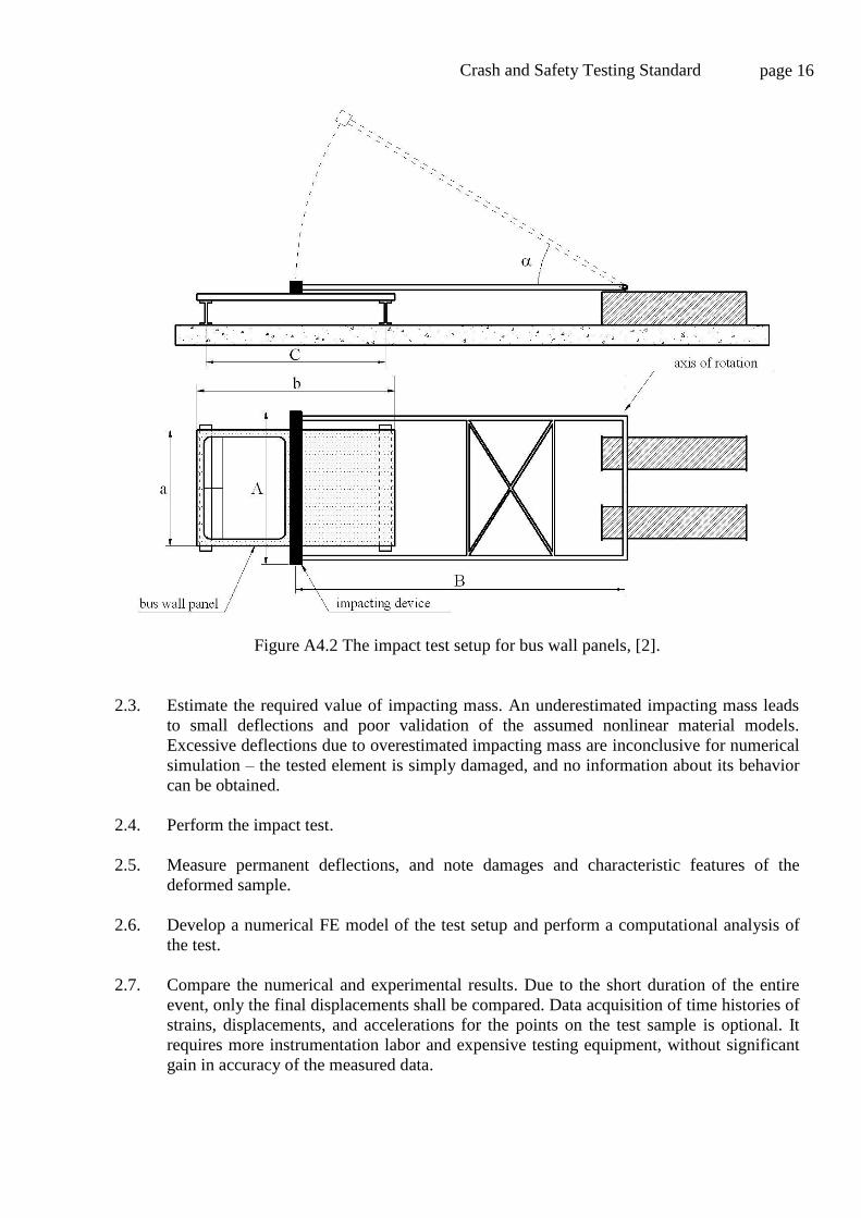
Figure A4.2 The impact test setup for bus wall panels, [2].
2.3. Estimate the required value of impacting mass. An underestimated impacting mass leads
to small deflections and poor validation of the assumed nonlinear material models.
Excessive deflections due to overestimated impacting mass are inconclusive for numerical
simulation – the tested element is simply damaged, and no information about its behavior
can be obtained.
2.4. Perform the impact test.
2.5. Measure permanent deflections, and note damages and characteristic features of the
deformed sample.
2.6. Develop a numerical FE model of the test setup and perform a computational analysis of
the test.
2.7. Compare the numerical and experimental results. Due to the short duration of the entire
event, only the final displacements shall be compared. Data acquisition of time histories of
strains, displacements, and accelerations for the points on the test sample is optional. It
requires more instrumentation labor and expensive testing equipment, without significant
gain in accuracy of the measured data.
Crash and Safety Testing Standard page 17
2.8. Modify the original assumptions used for the numerical model. If necessary, the additional
experimental tests shall be carried out.
3. Experimental setup. The experimental setup is built with welded steel elements, and
placed on a flat, solid concrete surface. Due to heavy supporting elements, no additional
fixing elements shall be used in order to prevent the lateral sliding of the supports during
the impact. The test device, presented in Figure A4.2, consists of the following parts:
3.1. An impacting frame, with necessary stiffeners. The impacting beam is A=2,445 mm (96”)
long. Both arms are B=3,020 mm (119”) long. The impacting beam is hollow with
adjustable mass. Its mass can be increased by filling it with water, or by adding solid
weights on its top.
3.2. A supporting structure, connecting the frame with heavy solid support.
3.3. Supports for the test sample, at the distance C, Figure A4.2.
3.4. A lifting device with a pulley and adequate release mechanism.

Crash and Safety Testing Standard page 18
Appendix 5
CENTER OF GRAVITY OF THE VEHICLE
1. General principles
1.1. The total energy to be absorbed during a bus rollover directly depend on the location of
the vehicle center of gravity (CG). Therefore, its determination shall be as accurate as
possible. The method of measurement of dimensions, angles and load values, and the
accuracy of measurement shall be recorded for assessment by a qualified technical service.
The following accuracy of measuring is required [1]:
o for measurements smaller than 2,000 mm, accuracy of 1 mm
o for measurements greater than 2,000 mm, accuracy of 0.05 per cent
o for measured angles, accuracy of 1 per cent
o for measured load values accuracy of 0.2 per cent
The wheel-base(s) and the distance between the centers of the footprint of the wheel(s) at
each axle (the track of each axle) shall be determined from the manufacturer's drawings.
1.2. Blocked suspension is specified as the condition for determining centre of gravity and for
carrying out the actual rollover test. The suspension shall be blocked in the normal
operating position as defined by the manufacturer.
1.3. The position of the CG is defined by the following three parameters:
1.3.1. longitudinal distance (l1) from the center line of front axle,
1.3.2. transverse distance (t) from the vertical longitudinal central plane of the vehicle,
1.3.3. vertical height (h0) above the flat horizontal ground level when all tires are inflated as
specified for the vehicle.
1.4. A method for determining l1, t, h0, using load cells is outlined below. Alternative methods
using lifting equipment and/or tilt tables for example may be considered by the technical
service which will decide if the method is acceptable based on its degree of accuracy (see
paragraph 1.1. above).
1.5. The CG position of the unloaded vehicle (unloaded curb mass Mk) shall be determined by
measurements, as follows.
2. Measurements
2.1. The longitudinal (l1) and transverse (t) coordinates of CG shall be determined on a
common horizontal ground (see Figure A5.1) where each wheel or twinned wheel of the
vehicle is standing on an individual load cell. Each steered wheel shall be set to its
straight-ahead position.
2.2. The individual load-cell readings shall be noted simultaneously and shall be used to
calculate the total vehicle mass and the CG position.
Crash and Safety Testing Standard page 19
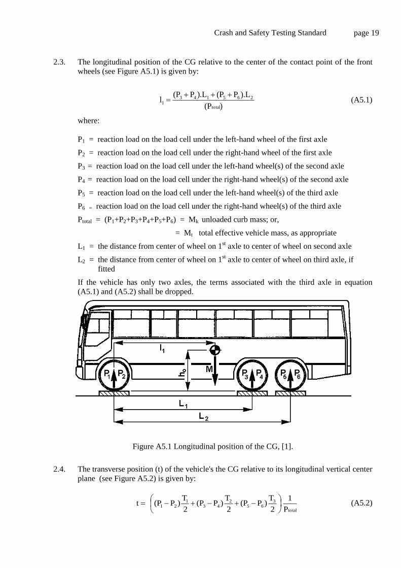
2.3. The longitudinal position of the CG relative to the center of the contact point of the front
wheels (see Figure A5.1) is given by:
)(P
).LP(P).LP(Pl
total
2651431
(A5.1)
where:
P1 = reaction load on the load cell under the left-hand wheel of the first axle
P2 = reaction load on the load cell under the right-hand wheel of the first axle
P3 = reaction load on the load cell under the left-hand wheel(s) of the second axle
P4 = reaction load on the load cell under the right-hand wheel(s) of the second axle
P5 = reaction load on the load cell under the left-hand wheel(s) of the third axle
P6 = reaction load on the load cell under the right-hand wheel(s) of the third axle
Ptotal = (P1+P2+P3+P4+P5+P6) = Mk unloaded curb mass; or,
= Mt total effective vehicle mass, as appropriate
L1 = the distance from center of wheel on 1st axle to center of wheel on second axle
L2 = the distance from center of wheel on 1st axle to center of wheel on third axle, if
fitted
If the vehicle has only two axles, the terms associated with the third axle in equation
(A5.1) and (A5.2) shall be dropped.
Figure A5.1 Longitudinal position of the CG, [1].
2.4. The transverse position (t) of the vehicle's the CG relative to its longitudinal vertical center
plane (see Figure A5.2) is given by:
total
365
243
121
P
1.
2
T)P(P
2
T)P(P
2
T)P(Pt
(A5.2)

Crash and Safety Testing Standard page 20
where:
T1 = distance between the centers of the footprint of the wheel(s) at each end of the first
axle,
T2 = distance between the centers of the footprint of the wheel(s) at each end of the
second axle,
T3 = distance between the centers of the footprint of the wheel(s) at each end of the third
axle.
If the value of (t) is negative, then the CG of the vehicle is located to the right of the
centerline of the vehicle.
Figure A5.2 Transverse position of center of gravity, [1].
2.5. The vertical location of the CG (h0) shall be determined by tilting the vehicle
longitudinally and using individual load-cells at the wheels of two axles.
2.5.1. Two load-cells shall be positioned on a common horizontal plane, to accommodate the
front wheels. The horizontal plane shall be at sufficient height above the surrounding
surfaces that the vehicle can be tilted forward to the required angle (see section 2.5.2.
below) without its nose touching that surface.
2.5.2. A second pair of load-cells shall be placed in a common horizontal plane on top of support
structures to support the wheels of the second axle of the vehicle. The support structures
shall be sufficiently tall to generate a significant tilt angle (> 20) for the vehicle. An
increased angle results in more accurate location of the CG – see Figure A5.3. The
vehicle is repositioned on the four load-cells, with the front wheels blocked to prevent the
vehicle from rolling forward. Each steered wheel shall be set to its straight-ahead steer
position.
2.5.3. The individual load-cell readings shall be noted simultaneously and shall be used to check
the total vehicle mass and its center of gravity position.
2.5.4. The tilt angle shall be determined by the Equation A5.3, (see also Figure A5.3):
1
1-inL
Hs (A5.3)

Crash and Safety Testing Standard page 21
where:
H = height difference between the footprints of the wheels of the first and second axles
L1 = the distance from the center of wheel first and second axles
2.5.5. The unloaded mass of the vehicle shall be checked as follows:
Ftotal = F1+F2+F3+F4 Ptotal Mk (A5.4)
where:
F1 = reaction load on the load cell under the left hand wheel of the first axle
F2 = reaction load on the load cell under the right hand wheel of the first axle
F3 = reaction load on the load cell under the left hand wheel of the second axle
F4 = reaction load on the load cell under the right hand wheel of the second axle
If this equation is not satisfied, the measurement shall be repeated and/or the manufacturer shall
be asked to modify the value of the unloaded curb mass in the technical description of the vehicle.
2.5.6. The height (ho) of the vehicle CG is given by:
total
oP
FFLlrh 43
11tan
1
(A5.5)
where:
r = a vertical distance between the wheel center (on first axle) and the load cell top surface
Figure A5.3 A test the vertical location of the CG, [1].
Crash and Safety Testing Standard page 22
Appendix 6
SIDE IMPACT TEST
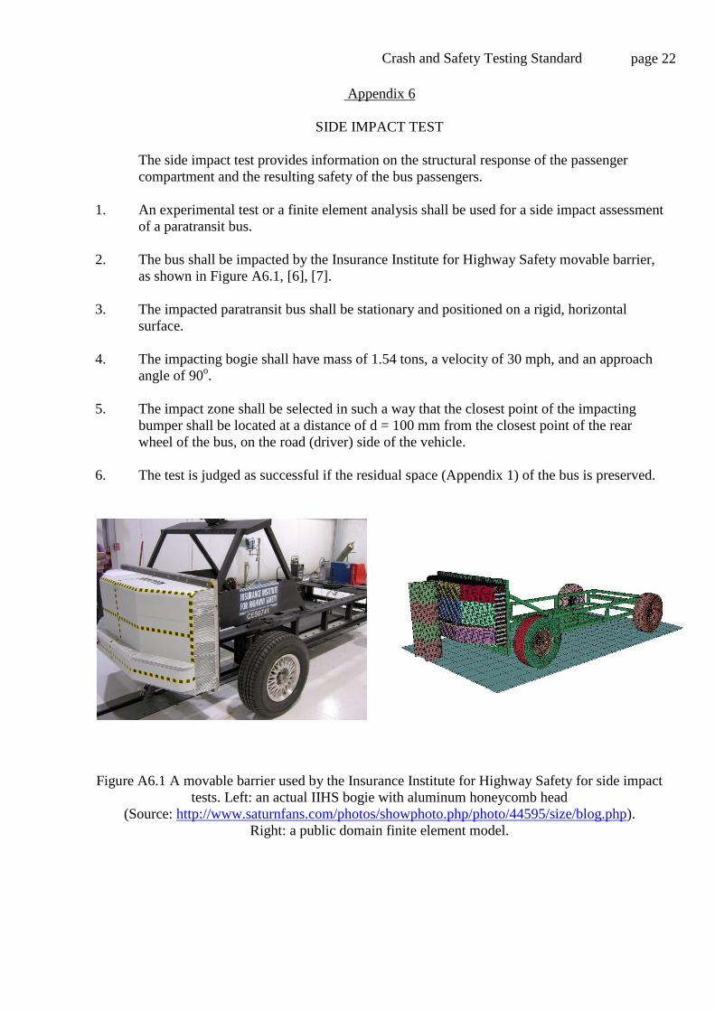
The side impact test provides information on the structural response of the passenger
compartment and the resulting safety of the bus passengers.
1. An experimental test or a finite element analysis shall be used for a side impact assessment
of a paratransit bus.
2. The bus shall be impacted by the Insurance Institute for Highway Safety movable barrier,
as shown in Figure A6.1, [6], [7].
3. The impacted paratransit bus shall be stationary and positioned on a rigid, horizontal
surface.
4. The impacting bogie shall have mass of 1.54 tons, a velocity of 30 mph, and an approach
angle of 90o.
5. The impact zone shall be selected in such a way that the closest point of the impacting
bumper shall be located at a distance of d = 100 mm from the closest point of the rear
wheel of the bus, on the road (driver) side of the vehicle.
6. The test is judged as successful if the residual space (Appendix 1) of the bus is preserved.
Figure A6.1 A movable barrier used by the Insurance Institute for Highway Safety for side impact
tests. Left: an actual IIHS bogie with aluminum honeycomb head
(Source: http://www.saturnfans.com/photos/showphoto.php/photo/44595/size/blog.php).
Right: a public domain finite element model.

Crash and Safety Testing Standard page 23
Appendix 7
ROLL-OVER TEST
The rollover test of a complete vehicle shall be performed on a tilt table (see Figure A7.1),
as follows:
1. The complete vehicle is placed on a tilt table, with blocked suspension and is tilted slowly
with its CG moving to its unstable equilibrium position CG‟, as shown in Figure A7.1. If
the vehicle type is not fitted with occupant restraints it will be tested at unloaded curb
mass. If the vehicle type is fitted with occupant restraints it will be tested at total effective
vehicle mass;
2. The rollover test starts in this unstable vehicle position (CG‟) with zero angular velocity
and with the axis of rotation running through the wheel-ground contact points. At this
moment the vehicle is characterized by reference energy ER (CG‟, see Figure A7.1).
3. The vehicle tips over into a ditch, having a horizontal, dry and smooth concrete ground
surface with a nominal depth of 800 mm;
4. The detailed technical specification of the rollover test on a complete vehicle as the basic
approval test is provided in [1].
Figure A7.1 Specification of the rollover test on a complete vehicle showing the path of the center
of gravity from the initial CG point, through the unstable equilibrium CG‟, until the crashed
position CG”, when the cantrail touches the ground[1].

Crash and Safety Testing Standard page 24
Appendix 8
PRE-APPROVAL
A complete crashworthiness and safety assessment process, as described in this document,
is very detailed and long. The following sub-set of faster, experimental tests (as shown in
Figure 1) is required to predict if the paratransit bus is likely to pass the complete
assessment process:
a. Material testing of major structural parts of the bus body (Appendix 2)
b. Quasi-static tests of roof-to-wall and wall-to-floor connections (Appendix 3), and
c. Impact hammer test of a bus side wall panel (Appendix 4).
1. Positive results of these tests shall be required to request a pre-approval status.
2. A full crashworthiness and safety assessment process for the paratransit bus shall be
completed within a year from the time of the initial pre-approval to secure the approval
status.

Crash and Safety Testing Standard page 25
REFERENCES
[1] United Nations Economic Commission for Europe Regulation 66, Addendum 65, Uniform
technical prescriptions concerning the approval of large passenger vehicles with regard to
the strength of their superstructure Feb, 22, 2006 http://www.unece.org/ trans/ main/
wp29/ wp29regs/ r066r1e.pdf
[2] Official Journal of the European Communities Directive 2001/85/EC relating to special
provisions for vehicles used for the carriage of passengers comprising more than eight
seats in addition to the driver's seat, November, 2001
http://eur-lex.europa.eu/LexUriServ/LexUriServ.do?uri=CELEX:32001L0085:EN:NOT
[3] Christopher Green, Bus body structural integrity analysis, final report. Michigan
Department of Transportation, December 1998.
[4] United Nations Economic Commission for Europe Regulation 66 Strength of the
superstructure of large passenger vehicles
http://www.unece.org/trans/main/wp29/wp29regs61-80.html
[5] United Nations Economic Commission for Europe Regulation 107 Double-deck large
passenger vehicles http://www.unece.org/trans/main/wp29/wp29regs101-120.html
[6] Insurance Institute for Highway Safety, Side Impact Crashworthiness Evaluation. Crash
Test Protocol (Version V), May 2008 (last visited: October 2009).
http://www.iihs.org/ratings/protocols/pdf/test_protocol_side.pdf
[7] Insurance Institute for Highway Safety, Side Impact Crashworthiness Evaluation. Moving
Deformable Barrier Specifications, October 2007 (last visited: October 2009).
http://www.iihs.org/ratings/protocols/pdf/side_barrier_spec.pdf