fuji ed & c times news letter vol.15
TRANSCRIPT

TIME015
Vol. 15
New ProductsMini Contactors and Thermal Overload Relays SK Series, Models 06, 09, and 12 ...................................... 2
Miniature control relays HH52-C, HH53-C, HH54-C Series .......................................................................... 6
Instrument Panel Cam Switches AK8 Series ................................................................................................ 8
Molded Case Circuit Breakers BW0 series 32AF/400AF ............................................................................ 10
Miniature Circuit Breakers BE1 Series ........................................................................................................ 14
Air Circuit Breakers BT2 Series ................................................................................................................... 16
Transducers WS2 Series ............................................................................................................................. 18
Fuji Electronic Meters Three-phase Current/Voltage Meters WE1SA and 1SV ........................................... 20
Energy Monitoring Units F-MPC Series One-circuit AC Energy Monitoring Unit F-MPC04E ...................... 22
Energy Monitoring System F-MPC I/O Unit ................................................................................................. 24
Split-type Current Transformers CC2D ........................................................................................................ 26
AC Power Regulators APR-D Series ........................................................................................................... 28
Three-phase Rail-mounting Power Filters RNFTD and RNFDS Series ...................................................... 30
Thermostat-type Temperature Switches PQ Series .................................................................................... 32
High-voltage Distribution Overcurrent Relays QHA-OC1 and QHA-OC2 .................................................... 34
NoticesModed Cased Circuit Breakers and Earth Leakage Circuit Breakers
Marketing of G-TWIN-series IP-reinforced Terminal Covers........................................................................ 36
Modified ProductsChanged Models ......................................................................................................................................... 37
Discontinued ProductsDiscontinued Products ................................................................................................................................. 39

FUJI ED & C TIMES Vol. 15
New ProductsNew Products
2
Mini Contactors and Thermal Overload RelaysSK Series, Types 06, 09, and 12
The Smallest Class of Magnetic Contactors and Thermal Overload Relays in the World.
Features• International safety standards for standard models (IEC, GB,
JIS, UL, and CSA).• Models available with AC or DC operating coils (DC: 2.4W
and 1.2W models only).• Many optional units. Auxiliary Contact Blocks (2-pole or 4-pole) Coil Surge Suppression Units Interlock Units• Easier Thermal Overload Relay wiring. The terminal arrangement separates main circuit wires and
auxiliary circuit wires for easier wiring.
Types and Ratings• Magnetic ContactorsFramesize②
Max. motor capacity [kW] Rated operational current [A] Conventional free air thermal current [A] (Rated thermal current)
Operating coilspecification③
Auxiliary contactspecification④
Auxiliary contactarrangement⑥
Type3-phase squirrel-cage motor(AC-3)
3-phase squirrel-cage motor(AC-3)
200-240V
380-440V
500-550V
200-240V
380-440V
500-550V
6A[06]
1.5 2.2 3 6 6 5 20 AC-operated[A]
Bifurcated [blank] 1NO [10]1NC [01]
SK06A-□▲Single [H] SK06AH-□▲
DC-operated (2.4W) [G]
Bifurcated [blank] SK06G-□▲Single [H] SK06GH-□▲
DC-operated (1.2W)[L]
Bifurcated [blank] SK06L-□▲Single [H] SK06LH-□▲
9A[09]
2.2 4 4 9 9 7 AC-operated [A]
Bifurcated [blank] SK09A-□▲Single [H] SK09AH-□▲
DC-operated (2.4W)[G]
Bifurcated [blank] SK09G-□▲Single [H] SK09GH-□▲
DC-operated (1.2W)[L]
Bifurcated [blank] SK09L-□▲Single [H] SK09LH-□▲
12A[12]
3 5.5 5.5 12 12 9 AC-operated[A]
Bifurcated [blank] SK12A-□▲Single [H] SK12AH-□▲
DC-operated (2.4W)[G]
Bifurcated [blank] SK12G-□▲Single [H] SK12GH-□▲
DC-operated (1.2W)[L]
Bifurcated [blank] SK12L-□▲Single [H] SK12LH-□▲
Note 1. “□” in the type column is replaced with the coil voltage code.Note 2. Numbers and letters in brackets [ ] are used in the product code.
• Coil voltage ⑤AC-operated Order Voltage 24 48 100 110 120 200 220 240 380 400 440 500
Product code E F 1 H K 2 M P S 4 T 5DC-operated (2.4W) Order Voltage 12 24 48 60 100 110 120 200 210 220
Product code B E F G 1 H K 2 Y MDC-operated (1.2W) Order Voltage 12 24 48
Product code B E F
Ordering Information (Types)• Magnetic Contactors
SK12L
①Series②Frame size③Operating coil specification
④Auxiliary contact specification⑤Coil voltage specification ⑥Auxiliary contact arrangement
SK 06 A H - E 10① ② ③ ④ ⑤ ⑥

FUJI ED & C TIMES Vol. 15
New Products
3
Mini Contactors and Thermal Overload Relays SK Series, Types 06, 09, and 12
• Magnetic Starters (reference) SK□ + TK12
Dimensions, mm• Magnetic Contactors SK06□, SK09□, SK12□
(34)*1(17)*2
6
61 (rail height: 15)
3649
2-M4 mounting holes
40
Coil terminalM3.5
Aux. terminal M3.5
Main terminals M3.5
7.7
48 31
458.7
** For DC-operated models.
*
*
Mount the Auxiliary Overload Relay with two mounting holes in diagonally opposed corners.
Mass : 0.14kg (For AC-operated models.) 0.17kg (For DC-operated models.)
[NOTE]
Auxiliary contacts
1NO 1NC
Mounting Hole Dimensions
[NOTES]*1 With SZ1KA□ Auxiliary Contact Blocks.*2 With SZ1FA□ Auxiliary Contact Blocks.
-A214 T36T24T12
+A1NO13L35L231 L1
35
**
**
14
13 5/L3 3/L2 1/L1
2/T1 4/T2 6/T3 A2 (-)
A1 (+)
**
**A1 (+)
A2 (-)
1/L1
2/T1 6/T3 4/T2
3/L2 5/L3 21
22
Wiring diagram
(17) *2(34) *1
2-M4 mounting holes
-A214 T36T24T12
+A1NO13L35L23L11
Aux. terminalsM3.5 (NC)
Aux. terminals M3.5 (NO)
Main terminalsM3.5
Main terminalsM3.5
Aux. terminal M3.5
Coil terminal M3.5
Trip indicator (sequence check)Reset button
40.5
79
8.7 7.7
97.5
644831
8.5
458.7 7.7
A5037
61 (rail height: 15)49
366
Mounting Hole Dimensions
40
35
Dimension A- Manually reset state: 5mm- Automatically reset state: 2mm
[NOTE]Mount the Auxiliary Overload Relay with two mounting holes in diagonally opposed corners.
[NOTES]*1 With SZ1KA□ Auxiliary Contact Blocks.*2 With SZ1FA□ Auxiliary Contact Blocks.
A1(+)**
A2(-) **
2/T1 4/T2 6/T3 9698
959714
13 5/L3 3/L2 1/L1
**A1(+)
A2(-) **
2/T1 4/T2 6/T3 9698
21 5/L3 3/L2 1/L1
22 97 95
Mass : 0.24kg (AC-operated model) 0.27kg (DC-operated model)
** For DC-operated models.
Auxiliary contacts
1NO 1NC
Wiring diagram

FUJI ED & C TIMES Vol. 154
New Products Mini Contactors and Thermal Overload Relays SK Series, Types 06, 09, and 12
Features• International safety standards for standard models (IEC, GB,
JIS, UL, and CSA).• A terminal cover and dial cover are provided as standard
features.• Highly reliable 1NO1NC isolated auxiliary contacts to enable
using NC and NO contacts at different potentials.• Easily switch between manual and automatic reset.• Parallel arrangement of main terminals and auxiliary
terminals for easier wiring.
TK12
Ratings and TypesTypeTK12W□−■■■
Note : “□” in the type column is replaced with the reset method code. “■■■” is replaced by the specified code for the current setting range.
Ampere Setting Range Specification CodesAmpere settingrange [A]
Code Applicable Magnetic Contactors
0.1 - 0.15 P10 SK06 SK09 SK12 0.13 - 0.2 P13 0.18 - 0.27 P18 0.24 - 0.36 P24 0.34 - 0.52 P34 0.48 - 0.72 P48 0.64 - 0.96 P64 0.8 - 1.2 P80 0.95 - 1.45 P95 1.4 - 2.1 1P4 1.7 - 2.6 1P7 2.2 - 3.4 2P2 2.8 - 4.2 2P8 4 - 6 004 5 - 7.5 005 − 6 - 9 006 7 - 10.5 007 − 9 - 13 009
Type number nomenclature
9597
9698 6/T3 4/T2
Dimension A ・For manual reset: 5mm ・For automatic reset: 2mm
Mass: 0.1kg
2/T1
Wiring Diagram
Main terminalsM3.5
Reset button
SK□
Trip indication (sequence check)
Auxiliary terminalsM3.5 (NC)Auxiliary terminalsM3.5 (NO)
3410.5
17.5
44
4.9
40
A37
50
(97
.5)
7.78.7
4540.5
Dimensions, mmTK12
Ampere setting range *Refer to Ampere setting range specification codes.
TK 12 W A - 009Basic type number
TK : 2E Thermal Overload Relay (with phase-loss detection)
MountingW : On-contactor mounting
Reset methodBlank : Manual reset (standard)
A : Automatic reset
Frame size12

FUJI ED & C TIMES Vol. 15
New Products
5
Mini Contactors and Thermal Overload Relays SK Series, Types 06, 09, and 12
OptionProduct name Type Main specifications Applicable Types
Auxiliary Contact Blocks (head-on, double contacts)
SZ1KA40 Contact arrangement: 4NO SK06 to SK12 *1SKH4 *1SZ1KA31 Contact arrangement: 3NO+1NC
SZ1KA22 Contact arrangement: 2NO+2NC
SZ1KA13 Contact arrangement: 1NO+3NC
SZ1KA04 Contact arrangement: 4NC
SZ1KA20 Contact arrangement: 2NO SK06 to SK12 SKH4 SZ1KA11 Contact arrangement: 1NO+1NC
SZ1KA02 Contact arrangement: 2NC
Auxiliary Contact Blocks (head-on, single contacts) SZ1KA40H Contact arrangement: 4NO SK06 to SK12 *1SKH4 *1SZ1KA31H Contact arrangement: 3NO+1NC
SZ1KA22H Contact arrangement: 2NO+2NC
SZ1KA13H Contact arrangement: 1NO+3NC
SZ1KA04H Contact arrangement: 4NC
SZ1KA20H Contact arrangement: 2NO SK06 to SK12SKH4SZ1KA11H Contact arrangement: 1NO+1NC
SZ1KA02H Contact arrangement: 2NC
Auxiliary Contact Blocks (small head-on, double contacts)
SZ1FA11 Contact arrangement: 1NO+1NC SK06 to SK12SKH4
Auxiliary Contact Blocks (small head-on, single contacts)
SZ1FA11H Contact arrangement: 1NO+1NC SK06 to SK12SKH4
Interlock Units SZ1KRM For reversed assembly, mechanical interlock SK06 to SK12
Power connection kit for reversing (Wiring) SZ1KRW1W Power connection kit for reversing for main circuit SK06 to SK12
Main Circuit Surge Suppression Unit *2 SZ-ZM2 Built-in CR (3-phase motor, 200V, 0.1 to 2.2kW) SK06 to SK12
Stand-alone Installation Unit *2(for Main Circuit Surge Suppression Unit)
SZ-ZMH Main Circuit Surge Suppression Unit SK-ZM2SK-ZM2E
Coil Surge Suppression Units (surge Suppression only)
SZ1KZ1 Built-in varistor: 24 to 48V AC/DC SK06 to SK12SKH4SZ1KZ2 Built-in varistor: 48 to 125V AC/DC
SZ1KZ3 Built-in varistor: 100 to 250V AC/DC
Coil Surge Suppression Units (with operation indicator)
SZ1KZ4 Built-in varistor and LED: 24 to 48V AC/DC SK06 to SK12SKH4SZ1KZ5 Built-in varistor and LED: 48 to 125V AC/DC
Operation Indicator Unit SZ1KL1 Built-in LED: 12 to 24V AC/DC SK06 to SK12SKH4SZ1KL2 Built-in LED: 24 to 48V AC/DC
SZ1KL3 Built-in LED: 48 to 125V AC/DC
Thermal Overload Relay Reset Release SZ-R1 Release length: 300mm TK12
SZ-R2 Release length: 500mm
SZ-R3 Release length: 700mm
Connection Module BZ0LRK12AA For linking with Manual Motor Starter SK06 to SK12
Power connection kit for reversing (Insert Molding) SZ1KRW1M Power connection kit for reversing (Insert Molding) for main circuit
SK06 to SK12
Types: *1 Not applicable to DC 1.2W Magnetic Contactors or Motor Starters (SK06 to SK12L) and SKH4L Auxiliary Relays. *2 Use the SZ-ZMH Stand-alone Installation Unit together with the SZ-ZM2 Main Circuit Surge Suppression Unit.

FUJI ED & C TIMES Vol. 15
New ProductsNew Products
6
Miniature control relaysHH52-C, HH53-C, HH54-C Series
Miniature Control Relays with Special Sockets (2P, 3P and 4P) That Are Ideal for the China/Asian Market.
HH54P-LC
HH52P-LCHH53P-LC
Features• The products have obtained the CCC certification and can
satisfy the market demands.• Standard products have been approved by UL, CSA and
TÜV.• The series products are equipped with an operating indicator
(LED), ensuring a clear glance of work status.• The products are environmentally friendly and conformed
to regulations on pollution control of electronic information products.
Type number nomenclature
Types
HH 54 P L C DC 24V-
Basic type
HH Miniature control relay
P Plug-in
Rated coil voltage
C CCC certified product
DC24V
DC48V
AC110V
AC220V
L With an operating indicator
Contact arrangement
52 2PDT
53 3PDT
54 4PDT
24V DC coil
48V DC coil
110V AC coil
220V AC coil
Contact arrangement
Rated thermal current (A)
Operating indicator Rated coil voltage *1 Type Applicable socketsAC coil DC coil
2PDT 5 Not equipped AC110VAC220V
DC24VDC48V
HH52P-C TP58X1-CTP58X1-ECEquipped HH52P-LC
3PDT 5 Not equipped HH53P-C TP511X1-CEquipped HH53P-LC TP511X1-EC
4PDT 3 Not equipped HH54P-C TP514X1-CTP514X1-ECEquipped HH54P-LC
*1 Please consult our company for the voltage specifications of other coils not mentioned in the above table
Type
Coil voltage
CE mark (in conformity with the low voltage requirement)
Approved by CCC certification
Rated value of contactHH52P:5AHH53P:5AHH54P:3A
Operating indicator (LED)LED is on during operation.• AC coil: red• DC coil: green
Major overseas–standard-based certifications• UL and CSA certification• Deemed by TÜV as being in conformity with IEC standard
*For HH52P-LC, HH53P-LC and HH54P-LC

FUJI ED & C TIMES Vol. 15
New Products
7
Miniature control relays HH52-C, HH53-C, HH54-C Series
Internal wiringsStandardHH52P-C HH53P-C HH54P-C
4 8 12
1 5 9 13
14
(-)
(+)
3 6 9
1 4 7
2 5 8
13
14
(-)
(+)
4 8 12
1 5 9
14
13
2
3 7
6 10
11
(+)
(-)
Equipped with an operating indicatorHH52P-LC HH53P-LC HH54P-LC
4 8 12
1 5 9
14
13
(+)
(-)
3 6 9
1 4 7
2 5 8
14
13
(+)
(-)
4 8 12
1 5 9
2
3 7
6 10
11
14
13
(+)
(-)
Voltage Make Break Electrical life (million)Current(A)
Power factor or time constant
Current(A)
Power factor or time constant
HH52PHH53P
HH54P
AC 200V(Ind. load)
10 cosø=0.7 1 cosø=0.3 to 0.4
0.4 0.085 0.5 1 0.23 0.3 1.7 0.331 0.1 6 1.2
AC 100V(Ind. load)
10 cosø=0.7 1 cosø=0.3 to 0.4
0.7 0.135 0.5 1.5 0.283 0.3 2.8 0.51 0.1 9 1.7
AC 200V(Res. load)
3 cosø=1 3 cosø=1 0.6 0.151 1 2 0.50.3 0.3 8 2
AC 100V(Res. load)
3 cosø=1 3 cosø=1 1 0.251 1 3.4 0.90.3 0.3 14 3.5
DC 100V(Ind. load)
0.2 T=15ms 0.2 T=15ms 0.4 0.150.05 0.05 2.4 0.9
DC 24V(Ind. load)
1 T=15ms 1 T=15ms 0.5 0.150.2 0.2 4 1.2
DC 100V(Res. load)
0.5 T=0ms 0.5 T=0ms 0.6 0.150.1 0.1 5 1.2
DC 24V(Res. load)
3 T=0ms 3 T=0ms 0.4 0.11 1 1.6 0.40.2 0.2 14 3.5
Item SpecificationsRated insulation voltage 250VOperating voltage AC 80% of the rated voltage (20°C)
DC 75% of the rated voltage (20°C)Reset voltage AC 30% of the rated voltage (20°C)
DC 10% of the rated voltage (20°C)Maximum voltagepersistently applied
110% of the rated voltage
Range of operatingtemperature
-25 to +60°CWhen 100% rated voltage is applied, no condensation or icing is observed.
Dielectric strength The coil contacts and c contacts are mutual voltage resistant.
AC2000V, 1 minute
Among the contact clearance AC1000V, 1 minuteAmong the socket terminal AC2000V, 1 minute
Insulation resistance Detected with a DC500V M meter; must be above 100MΩ
Operating time 20ms or lessReset time 20ms or lessVibration Malfunction 10 to 55 Hz, double amplitude 1mm
Durability 10 to 55 Hz, double amplitude 1mm2 hours for each of X, Y and Z direction, 6 hours in all
Shock Malfunction 200m/s2
Durability 1000m/s2, 3 times for each of X,Y and Z direction, 18 times in all.Durability Mechanical AC ratings: 50 million operations
DC ratings: 100 million operationsElectrical Please refer to table below
Contact resistance 50mΩ or less (Before use)Minimum applicable load(reference value) *
5V, 1mA
Mass HH52P-LC: Approx. 32gHH53P-LC: Approx. 33gHH54P-LC: Approx. 33g
Note *: Reliability index λ60=0.1×10⁻⁶/onceReferring to the minimum applicable load during the continual on-off when the relay is installed in a clean electrical cabinet. But this does not apply to the minimum applicable load during continual excitation work and etc.
Specifications Electrical durability
Dimensions, mmType, Appearance, mass
Dimensions, mm
HH52P-CHH52P-LC
4 8 12
1 5 9
14
13
0.5
27.8
212.8
1.2
2.2
5.7 34.9
Approx. 32gHH53P-CHH53P-LC
3 6 9
2 5 8
1 4 7
14
13
0.5
27.8
21
2.8
1.2
2.2
5.7 34.9
Approx. 33gHH54P-CHH54P-LC
4 8 12
1 5 9
14
13
0.5
27.8
21
2.8
1.2
2.2
5.7 34.9
3 7 11
2 6 10
Approx. 33g

FUJI ED & C TIMES Vol. 15
New ProductsNew Products
8
Instrument Panel Cam SwitchesAK8 Series
Switches to Switch Voltmeters and Ammeters
Features• Compact and easily connectable from the back.• External confirmation of contact operation.• Sliding contacts used for highly reliable operation.
TypesUsage Type Elements Notch symbols No. of notches × Angle of rotationAmmeters 3-phase, 3-wire, 2-CT AK8-AS3 2 OFF/R/S/T/OFF 5×45°
Single-phase, 3-wire, 2-CT AK8-AS1 2 OFF/R/O/T/OFFVoltmeters 3-phase, 3-wire, 2-VT AK8-VS3 2 OFF/R-S/S-T/T-R/OFF
Single-phase, 3-wire, 2-VT AK8-VS1 2 OFF/R-O/O-T/T-R/OFF
Ratings and SpecificationsOperating current [A]AC DC
Operating voltage [V]
Resistive load
Inductive load, power factor of 0.4
Resistive load
Inductive load
24 15 15 — —48 15 10.5 — —110 10 6.5 — —220 7 4.5 — —440 3 2 — —
Rated insulation voltage 600VOpen thermal current (rated carry current)
15A
Insulation resistance 100MΩ min. (500V insulation resistance tester)Dielectric strength 2,500V AC 1 minSwitching frequency 1,200 operations/h (usage rate: 40%)Durability (mechanical and electrical)
250,000 operations
Ambient operating temperature
−20 to 60°C (with no icing or condensation)
Ambient operating humidity 45% to 85% RH (at −5 to 40°C with no icing or condensation)Enclosure IP40 enclosure

FUJI ED & C TIMES Vol. 15
New Products
9
Instrument Panel Cam Switches AK8 Series
Dimensions, mm
Contact Unit
(1.6 to 4.5) (black = N1.5)(black = N1.5)Lobed knobEscutcheon
48 42
42
15.5×2=316
4855.517
15.5
(Phillips/slot combination pan head screw, spring washer and square washer with wire restraint)
Terminal screws, M3.5 × 8
Mounting panel thickness
65
60
Ø41
13 dia. hole
2-6 dia. hole
End marking
Mounting PanelDrilling Dimensions
PartsName and appearance Type Dimensions (unit: mm)Charging Section Cover AKX102
50
35 54222
Wiring Diagram • AK8-AS1, AS3
• AK8-AS1, AS3
87654321
A(3)(7) (1) (2)(8)
Short bar
Terminal number
58
63
58
63
(3)
(2)(1)
(8)
(7)
450
450 450
450
R S T(R)(O) (T)
OR
OFF
T
OFF
ACAMME T E R
SR
OFF
T
OFF
ACAMME T E R
AK8-AS1 (Single-phase, 3-wire) AK8-AS3 (3-phase, 3-wire)
Nameplate Details
Contact Arrangement Diagram
Notch Position Diagram(Front View)
87654321
(7) (1) (2)(8)
Short bar
Terminal number
V(3)
58
63
5863
AK8-VS1 (Single-phase, 3-wire) AK8-VS3 (3-phase, 3-wire)
R S T(R)(O) (T)
-O-R
O
FOF
-T R
TMETERLOVCA
T
F OF
-S-R
SF O
F FOF
-T R
TMETERLOVCA
T
Contact Arrangement Diagram

FUJI ED & C TIMES Vol. 15
New ProductsNew Products
10
BW0 series MCCB 32AF / 400AF
A Small 32AF Breaker Used in Branch Circuits Such as Those in Building and Control Panels.
FeaturesFocusing on assembly of easy wiring, maintenance check, reasonable price, and standardized distribution box or boards design, BW0 series MCCBs are designed mainly for civil building construction market and secondary distribution market.
400AFCassette type accessoriesAllaccessories can be assembled by the user. Quickly adaptable to the many onsite changes in specifications.
Compliance to RoHS DirectiveAll materials used are compliant to RoHS Directive and the main components are easy to recycle.
InterchangeabilityThe design of the same external dimensions with G-TWIN circuit breaker.Just simply change the model when a customer suddenly changes the design (e.g. when changed to earth leakage circuit breaker).
32AFCompact designCost and space saving for building a control panel.AC 440V application • Icu: 1.5kA at 440V AC, 2.5kA at 240V AC
Available accessoriesAuxiliary switch, alarm switch and shunt trip device
Compliance to RoHS DirectiveAll materials used are compliant to RoHS Directive and the main components are easy to recycle.
BW33A0 BW403S0

FUJI ED & C TIMES Vol. 15
New Products
11
BW0 series MCCB 32AF / 400AF
Line upSeries Breaker
ampereframe
Type Pole Rated current (A) InsulationvoltageUi (V)
Breaking capacity (kA) [Icu/Ics]IEC60947-2AC230V 380V 415V
BW0 32 BW32A0BW33A0
23
5, 10, 15, 20, 325, 10, 15, 20, 32
440440
2.5/22.5/2
1.5/11.5/1
1.5/11.5/1
400 BW402S0BW403S0
23
250, 300, 350, 400250, 300, 350, 400
690690
85/4385/43
36/1836/18
36/1836/18
• 32AF
Type number nomenclature
• 400AF
BW 3 2 A0 - 032 W K FA A
Product category BW : MCCB
Accessories
Terminal block A : with terminal block
Shunt trip device *1 FA : 100VAC to 120VAC FK : 200VAC to 240VAC FD : 100VDC
Alarm switch *2 K : 1c / alarm switch
Auxiliary switch *2 W : 1c / auxiliary switch
Frame size 3 : 32AF
Number of poles 2 : 2 poles 3 : 3 poles
Rated current 005 : 5A 010 : 10A 015 : 15A 020 : 20A 032 : 32A
Notes*1 A shunt trip device can be added only to 3-pole models.*2 Only one of the following can be added to a 2-pole model: alarm switch or auxiliary switch.
BW 40 3 S0 - 400
Series
Frame size 40 : 400AF
Number of poles 2 : 2-pole 3 : 3-pole
Rated current250 : 250A
A003 : 003 A053 : 053 A004 : 004

FUJI ED & C TIMES Vol. 1512
New Products
• 32AF
Frame 32APole 2 3Type BW32A0 BW33A0Rated current (A) 5, 10, 15, 20, 32Rated insulation voltage (VAC) 440[IEC 60947-2] (VDC) −Rated breaking capacity (kA) 500VAC − −[IEC 60947-2] 440VAC 1.5/1 1.5/1(Icu/Ics) *1 415VAC 1.5/1 1.5/1
400VAC 1.5/1 1.5/1380VAC 1.5/1 1.5/1240VAC 2.5/1 2.5/1230VAC 2.5/1 2.5/1250VDC − −
Rated operating voltage [UL508] (VAC) − −Dimensions (mm) a 36 54
b 80 80c 60 60d 76 76
Mass (kg) 0.18 0.25Tripping device Thermal-magneticFront mounting, front connectionInternal accessories Auxiliary switch (W)
Alarm switch (K)
Auxiliary switch + alarm switch (W+K) −
Shunt trip (F) − Undervoltage trip (R) − −External accessories Operating handle N-type − − Operating handle V-type − − Terminal cover Short − − Terminal cover Long BW9BTA0-L2 BW9BTA0-L3 Insulation barrier Interphase − − Flat terminal − − Block terminal − − Handle locking device − − IEC 35mm rail mounting Notes: *1 Icu: Rated ultimate short-circuit breaking capacity Ics: Rated service short-circuit breaking capacity
Available Factory mounted accessory − Not available
Types and specifications
a d c
b
BW0 series MCCB 32AF / 400AF

FUJI ED & C TIMES Vol. 15
New Products
13
• 400AF
Frame 400APole 2 3Type BW402S0 BW403S0Rated current (A) 250, 300, 350, 400Rated insulation voltage (VAC) 690[IEC 60947-2] (VDC) 250Rated breaking capacity (kA) 500VAC 20/10 20/10[IEC 60947-2] 440VAC 36/18 36/18(Icu/Ics) *1 415VAC 36/18 36/18
400VAC 36/18 36/18380VAC 36/18 36/18240VAC 85/43 85/43230VAC 85/43 85/43250VDC 20/10 20/10
Rated operating voltage [UL508] (VAC) − −Dimensions (mm) a 140 140
b 257 257c 103 103d 146 146
Mass (kg) Front mounting type 4.6 5.6Tripping device Thermal-magneticFront mounting, front connectionInternal accessories Alarm switch (W) BW9W1SHA BW9W1SHA Auxiliary switch (K) BW9K1SHA BW9K1SHA Auxiliary switch + alarm switch (W+K) − − Shunt trip (F) BW9FHA− BW9FHA− Undervoltage trip (R) BW9RHA− BW9RHA− External accessories Operating handle N-type BW9N0HA BW9N0HA Operating handle V-type BW9V0HA BW9V0HA Terminal cover Short BW9BTHA-S3 BW9BTHA-S3 Terminal cover Long BW9BTHA-L3 BW9BTHA-L3 Insulation barrier Interphase B-43A B-43A Flat terminal BW9SS0H0-2 BW9SS0H0-3 Block terminal − − Handle locking device − − IEC 35mm rail mounting − −Notes: *1 Icu: Rated ultimate short-circuit breaking capacity Ics: Rated service short-circuit breaking capacity
Available − Not available
a d c
b
BW0 series MCCB 32AF / 400AF

FUJI ED & C TIMES Vol. 15
New ProductsNew Products
14
Miniature Circuit BreakersBE1 Series
This series of miniature circuit breaker is for the purpose of the protection of distribution equipment in the residential or similar facility, to protect against short circuit and overload damage.
Features• Among the characteristics of overload protection, there
are the Curve C characteristic for the protection of lighting electrical systems having 5 to 10In instantaneous tripping characteristic, and the Curve D characteristic for the protection of ordinary electrical system wires having 10 to 14In instantaneous tripping characteristic.
• ELCB is completed by combining a miniature circuit breaker with an earth leakage shunt trip device.
• As functional components can be installed such as auxiliary switch, alarm switch among others, it can monitor and control the electrical system.
Miniature Circuit Breaker Standards
Application• Curve C: Illumination distribution system
Curve D: Industrial distribution system• Overload and short circuit protection
Standards and Certificates• IEC 60898-1, GB 10963.1• CE, CCC
Specifications• Rated voltage: AC230/400V, 50/60Hz• Rated current: curve C: 1 to 63A
curve D: 1 to 40A• Mechanical life: 10000 times• Tripping characteristic: curve C: 5 to 10In
curve D: 10 to 14In• Breaking capacity
Tripping characteristic
Rated current (A)
Rated operational voltage (V)
Rated breaking capacity (kA)
Curve C 1 to 40 230/400 6
50, 63 230/400 4.5
Curve D 1 to 40 230/400 4.5
Types
Number of poles Width (mm) Type
1P 18 BC63E1CG-1P
2P 36 BC63E1CG-2P
3P 54 BC63E1CG-3P
4P 72 BC63E1CG-4P
Miniature Earth Leakage Circuit Breaker Standards
Application• Clip onto the right side of BC32E1, BC50E1 series MCB
protection against earth leakage faults.
Standards and Certificates• IEC 61009-1, GB 16917.1• CCC
Specifications• Rated voltage: AC230/400V(1PN, 2P) 50Hz
AC400V(3P, 3PN, 4P) 50Hz• Rated current: 1 to 50A• Rated residual operating current: 30mA• Mechanical life: 20000 times• Instantaneous tripping characteristic: curve C: 5 to 10In• Breaking capacity
Tripping characteristic
Rated current (A)
Rated operational voltage (V)
Rated breaking capacity (kA)
Curve C 1 to 40 230/400 6
50 230/400 4.5
Types
Number of poles
Width (mm) Type
Miniature circuitbreaker
Earth leakageshunt trip
1N 18 27 BC32E1CL-1N
37 BC50E1CL-1N
2P 36 27 BC32E1CL-2P
37 BC50E1CL-2P
3P 54 36 BC32E1CL-3P
51 BC50E1CL-3P
3N 54 45 BC32E1CL-3N
64 BC50E1CL-3N
4P 72 45 BC32E1CL-4P
64 BC50E1CL-4P
BC63E1CG-4PBC63E1CG-1P

FUJI ED & C TIMES Vol. 15
New Products
15
Miniature Circuit Breakers BC-1 Series
Miniature Circuit Breaker (1P+N)
Application• TT/TN-S grounding system• Phase and neutral protection against short circuit and
overload
Standards and Certificates• IEC 60898-1, GB 10963.1• CCC
Specifications• Rated voltage: AC230V, 50/60Hz• Mechanical life: 10000 times• Tripping characteristic: C: 5 to 10In• Breaking capacity: 4.5kA
Types
Number of poles Width (mm) Type
1P+N 18 BC32E1CN-1P
Earth Leakage Circuit Breaker (1P+N)
Application• TT/TN-S grounding system• Phase and neutral protection against short circuit and
overload
Standards and Certificates• IEC 61009-1, GB 16917.1• CCC
Specifications• Rated voltage: AC230V, 50Hz• Mechanical life: 10000 times• Tripping characteristic: C: 5 to 10In• Rated residual operating current: 30mA• Breaking capacity: 4.5kA
Type
Number of poles Width (mm) Type
1P+N 36 BC32E1CLN-1P
Wiring Method
Use of phase line and neutral line series products in the
TT / TN-S systemsPhase line and neutral line are required to be switched in the TT (three-phase four-wire system)/TN-S (three-phase five-wire system) systems.
L1L2L3N
L1L2L3NPE
PE
TT
TN-S
Load Load Load
Load Load Load
Characteristic Curves BC32, BC50, BC63
• Curve C (5 to 10In)
1
2
46
1
2
46
Second
Ope
ratin
g tim
e
Minute
0.01
0.02
0.040.06
0.1
0.2
0.40.6
10
20
40
10
20
4060
120180
1 1.5 2 3 4 5 6 78 10 15 20 30 4050 60 80 100Multiple of rated current
Max. Value
Min. Value
Instantaneous tripping characteristic500 to 1000%
• Curve D (10 to 14In)
1
2
46
1
2
46
0.01
0.02
0.040.06
0.1
0.2
0.40.6
10
20
40
10
20
4060
120180
1 1.5 2 3 4 5 6 78 10 15 20 30 4050 60 80 100
Ope
ratin
g tim
e
Second
Minute
Max. Value
Min. Value
Multiple of rated current
Instantaneous tripping characteristic1000 to 1400%

FUJI ED & C TIMES Vol. 15
New ProductsNew Products
16
Air Circuit BreakersBT2 Series
New Models of 1600AF-6300AF Air Circuit Breakers That Comply with IEC Standards.
Features
• Breaking CapacityIcu is equal to Ics up to 120kA at maximum and Icw is up to 100kA at maximum under 400VAC distribution.
• Compact sizeBT2 series, Air Circuit Breakers, have fi ve framesize and four physical dimension sizes.
• InstallationThe bus bar terminal of the BT2 series, Air Circuit Breakers, can be simply installed as follows:- Horizontal connection- Vertical connection- Composite connection
• Safety performanceBT2 series, Air Circuit Breakers, are reliable by the following aspects:- Reliable assurance of the three positions: Connected Test Separatedby the locked and automatically unlocked mechanism at the draw-out socket.Clear indication of ready-for-switching-on to ensure safe manipulation and reliable operation.More reliable safety protection with seconday terminals of protection grade IP30
• Protection and selectionBT2 Series, Air Circuit Breakers, can implement selective interlock of ZSI Region to ensure comprehensive selection of various protection and reduce the copper bar's bearing of thermodynamic.
• Intelligent controller (OCR)Selecting OCR's, it can be classifi ed into six types.
Type number nomenclature
BT2-2500X(Draw-out type)
BT2-1600P(Fixed type)
OCR type or Additional accessories
Frame size1600, 2000, 2500, 4000, 6300
InstallationP: Fixed typeX: Draw-out type
Number of poles3: 3 poles4: 4 poles
Rated current1600AF: 0200, 0400, 0630, 0800, 1000, 1250, 16002000AF: 0630, 0800, 1000, 1250, 1600, 20002500AF: 1250, 1600, 2000, 25004000AF: 2000, 25000, 2900, 3200, 3600, 40006300AF: 4000, 5000, 6300
Basic type
CE version
BT2-2500P / 32500E

FUJI ED & C TIMES Vol. 15
New Products
17
Air Circuit Breakers BT2 Series
Intelligent controller (OCR)Selecting OCR's, it can be classified into six types
Type L25 M25 M26 H26 P25 P26Option Standard Option Option Option Option
Overcurrent protection(Long-time, Short-time, insantaneous)Ground-fault protection – – –Load monitor function –Indication Light Columnar LED LED LED LCD LCDPower, electric energy, power-factor, frequency indication – – –Alarm function (pre-trip alarm, overload alarm) – – – –Test function – – – – –Contact Welding indicationSelf-diagnosis function –MCR funciton –Fault-memory funciton –Current-imbalance indicationThermo-analogue function –Harmonic analysis function – – – –ZSI function –Communication function – – –
Note: Reprensents fundamental functions, Represents selective functions, – Represent no such functions
Types and specificationsFrame size 1600A 2000A 2500A 4000A 6300ABasic type BT2-1600 BT2-2000 BT2-2500 BT2-4000 BT2-6300No. of poles 3 4 3 4 3 4 3 4 3 4Rated current (A) 200, 400, 630, 800,
1000, 1250, 1600630, 800, 1000, 1250, 1600, 2000
1250, 1600, 2000, 2500
2000, 2500, 2900, 3200, 3600, 4000
4000, 5000, 6300
Rated current of the neutral pole (IN) 100% In 100% In 100% In 100% In 100% InRated insulation voltage (Ui) 1000 1000 1000 1000 1000Rated operational volage (Ue) 690 690 690 690 690Rated ultimate short-circuit breaking capacity(Icu kA, sym)
690VAC *1 40 50 50 75 85400VAC 50 80 85 100 120
Rated service short-circuit breaking capacity(Ics kA, sym)
690VAC *1 25 50 50 75 85400VAC 50 80 85 100 120
Rated making current(kA, peak)
690VAC *1 84 105 105 165 187400VAC 105 176 187 220 264
Rated short time withstand current(Icw) (kA, rms)
690VAC *1 25 (0.5s) 40 (1s) 50 (1s) 75 (1s) 85 (1s)400VAC 42 (0.5s) 60 (1s) 65 (1s) 85 (1s) 100 (1s)
Rated impulse withstand voltage (Uimp) (kV) 12 12 12 12 12Installations
Fixed PDraw-out X
Main circuit terminal connectionFixed Horizontal
Vertical – –
Draw-out HorizontalVertical
DimensionsFixed W 254 324 362 457 362 457 414 527 782 1008
H 320 320 395 395 395 395 395 395 395 395D 197 197 290 290 290 290 290 290 290 290
Draw-out W 248 318 347 442 347 442 401 514 767 993H 351.5 351.5 438 438 438 438 438 438 475.5 475.5D 297 297 390 390 390 390 395 395 395 395
Note: *1 Cannot be used for an IT distribution system.
Available

FUJI ED & C TIMES Vol. 15
New ProductsNew Products
18
TransducersWS2 Series
Transducers That Mount to a 16-slot Base Unit with Individual Power Switches. A Tester Can Be Used While the Transducer Is Mounted.
Features• Recommended for customers that line up many Transducers
for instrumentation.• Power switches are built into the multislot Base Unit. There’s
no need for separate switch boxes.• CE Marking for most Types.
Types and RatingsType and name Type Input Output 1 Output 2
Eight-slot Base Unit WS2BA-08 ― ― ―
Sixteen-slot Base Unit WS2BA-16
DC-isolated Transducer (Isolator) WS2DC DC voltage or current DC voltage or current DC voltage or current
DC-isolated Transducer (High-speed Isolator) WS2HS
DC-isolated Transducer (Super-high-speed Isolator) WS2US
Isolated Distributor WS2DY 4 to 20mA DC(24V DC)
Thermocouple Transducer WS2TC B, R, S, K, E, J, T, or N thermocouple
Resistance-bulb Transducer WS2PT PT100, 50, or JPT100Ω
Potentiometer Transducer WS2PM From 0 to 100 to 10kΩ
Tachogenerator Transducer WS2TG 220V or 24VP-P max., 0 to 1kHz
AC Voltage Transducer WS2CV 0 to 300V AC
AC Current Transducer WS2CA 0 to 5A AC
Analog Signal Selector WS2RP 4 to 20mA DC or 1 to 5V DC 4 to 20mA DC or 1 to 5V DC 4 to 20mA DC or 1 to 5V DC
Overspeed Detector (Monitor Relay) WS2MR No-voltage contacts, open-collector signal Optical MOSFET, 1NO contacts Optical MOSFET, 1NO contacts
Analog Output Setter (Manual Setter) WS2MS ― DC voltage or current DC voltage or current
Zero-speed Detector for Pulse Input WS2ZL Power Generator Unit speed: 10kHz Optical MOSFET, 1NO contacts ―
Zero-speed Detector for Sine Wave Input WS2ZA Power Generator Unit speed: 1kHz50V or 24VP-P max.
Optical MOSFET, 1NO contacts Optical MOSFET, 1NO contacts
Slow-pulse (F/V) Transducer WS2SP 0 to 10kHz DC voltage or current Open collector
Alarm Setter (2 sets of contacts) WS2AS DC voltage or current Relay contacts Relay contacts
Socket for Stand-alone Installation with 1 Output WS211 ― ― ―
Socket for Stand-alone Installation with 2 Outputs WS212
WS2 Series

FUJI ED & C TIMES Vol. 15
New Products
19
Transducers WS2 Series
Common SpecificationsItem SpecificationAuxiliary power supply inrush current (per unit)
Approx. 2.4A, 2.7ms max. at 24V DC, approx. 2.4A 1.0ms max. at 48V DC, approx. 2.2A 0.6ms max. at 110V DC, approx. 3.2A 0.6ms max. at 110V AC, and approx 6.3A 0.6ms max. at 220V AC
Momentary overload capability
Input 2 times rated voltage for 10 s10 times rated current for 5 s
Auxiliary power supply
1.5 times rated voltage for 10 s
Continuous overload capability
Input 1.2 times rated voltage continuouslyAuxiliary power supply
1.2 times rated voltage continuously
Insulation resistance Between all electric circuits and external case 50MΩ with 500V DC insulation resistance testerBetween input and output terminalsBetween I/O terminals and auxiliary power supply terminalsBetween alarm output 1 and alarm output 2 50MΩ with 500V DC insulation resistance testerBetween output 1 and output 2Between I/O terminals/selection signal terminals and auxiliary power supply
Dielectric strength Between all electric circuits and external case 2,000V AC (50/60Hz) 1 minHowever, 1,500V AC (50/60Hz) for 1 min between input and output terminals on the WH2HS or WH2US.
Between input and output terminalsBetween I/O terminals and auxiliary power supply terminalsBetween alarm output 1 and alarm output 2 500V AC (50/60Hz) 1 minBetween output 1 and output 2Between I/O terminals/selection signal terminals and auxiliary power supply
2,000V AC (50/60Hz) 1 min
Lightning impulse withstand voltage Between all electric circuits and external case 5kV 1.2/50μs 3 times each for positive and negative polesVibration resistance 16.7Hz, 4mm double amplitude 1 hour each in X, Y, and Z directionsShock resistance 294m/s2 3 times each in both directions on X, Y, and Z axesOperating temperature and humidity ranges
−10 to 55°C, 5% to 90% RH (with no condensation)
Storage temperature range −20 to 70°CExterior color Munsell N1.5 (black)Case material Fire-resistant ABS resin (V-0)
Dimensions, mm
*1 All ground terminals are internally connected. The ground terminals are insulated from the Base Unit (frame ground).*2 Two Transducers are used for one WS2AS Alarm Setter.
Wall Mounting• WS2BA-16□Y-B00
• WS2BA-08□Y-B00 • WS2BA Connection Diagram
• External Wiring Diagram
3-M4 screws 16-M4 screws128-M3 screws
*2 To ensure proper heat dissipation, observe the dimensions in the above figure during installation. To use accessories or separately sold items, provide extra room to allow space for wiring.
Use an IEC/DIN 35mm-wide reinforced rail.Recommended Product: TH35-15AL from Fuji Electric FA Components and Systems Co., Ltd.
*1 This example is for IEC 35mm rail (height of 15).
Rail Mounting
8-M4 screws64-M3 screws
3-M4 screws
Wiring duct
Wiring duct
Wiring duct 50 mm min. (1)
50 mm min. (1)
50 mm min. (1)
50 mm min. (1)
50 mm min.

FUJI ED & C TIMES Vol. 15
New ProductsNew Products
20
Fuji Electronic MetersThree-phase Current/Voltage Meters WE1SA and 1SV
Ideal for Measuring Three-phase Currents and Voltages for Distribution, Busbars, and Feeders.
Features• The same Type can be used for 3-phase 3-wire, single-
phase, and single-phase 3-wire systems. Specifications in parentheses are the measurement specifications: Three-phase Ammeter (peak demand, demand, and instantaneous demand), Three-phase Voltmeter (voltage and frequency).
• Displays one bar graph and four digital measurements at the same time.
• Three analog output circuits and one alarm output circuit are available. Output element can be selected with a setting. (Optional)
• Resetting is possible from an external control input. (Optional) Also, a setting can be used to select the alarm output, the maximum/minimum value and alarm output, or the maximum/minimum value.
• Use either an 85 to 264V AC or 80 to 143V DC power supply.• Mounting dimensions are compatibly with previous
110×110mm mechanical meters. Mounts to two holes on a diagonal line.
• Backlight provided as a standard feature. Set the backlight to light, not light, or go out automatically, and set the brightness (white light only). LED color: Green or white
• Types available for top-row and bottow-row mounting.• All Types are RoHS compliant (EU Directive 2002/95/EC).
Types and RatingsProduct name Type Input circuit Input rangeThree-phase Ammeter
WE1SA-AF511-000 3-phase 3-wireSingle-phaseSingle-phase 3-wirecommon use
5A
Three-phase Voltmeter
WE1SV-AFD11-000 150、300Vcommon use
Rating, Specifications, and Measurement RangesType WE1SA Ammeter WE1SV Voltmeter
Ratin
gs Input circuit/input 3-phase 3-wire, single-phase 3-wire, or single-phase
5A AC 50/60Hz 3-phase 3-wire, single-phase 110V or 220V common use, 50/60HzSingle-phase 3-wire 100 to 200A AC*1 50/60Hz
Spec
ificat
ions Measured element Current Voltage Frequency
Measurement range/display specifications
Peak demand, demand, and instantaneous demand; 5A to 30kA AC 150V to 750kV AC Range selected from 45 to 55Hz, 55 to 65Hz, or 45 to 65Hz.
Intrinsic error*2
Digital display ±0.5% ±0.5% ±0.5%Analog outputs*3 ±0.5% ±0.5% ±0.5%
Maximum measurement ○ ○ ○Minimum measurement ○ ○ ○Bar graph display The main monitoring element can be set for a bar graph display and secondary monitoring elements can also be displayed.Operating method Current: Effective value calculation, Demand current: Calculation according to
thermomotive TypeVoltage: Effective value calculation, Frequency: Zero-cross frequency calculation
Time setting
Demand current 0 s, 5 s, 10 s, 20 s, 30 s, 40 s, 50 s, 1 min, 2 min, 3 min, 4 min, 5 min, 6 min, 7 min, 8 min, 9 min, 10 min, 15 min, 20 min, 25 min, or 30 min (95% time)
−
Display-selectable elements
Main monitor Current (each phase), demand current (each phase), or peak demand current (each phase)
Voltage (each phase and line) or frequency
Secondary monitor (left)
Current (each phase) Voltage (each phase and line)
Secondary monitor (middle)
Current (each phase), demand current (each phase), or peak demand current (each phase)
Voltage (each phase and line)
Secondary monitor (right)
Current (each phase), demand current (each phase), or peak demand current (each phase)
Voltage (each phase and line) or frequency
Bar graph Current (each phase), demand current (each phase), or peak demand current (each phase)
Voltage (each phase and line) or frequency
Options Analog outputs (3 circuits), 1 alarm output, and 1 external control inputRemarks Phase switched between R, S, and T.*4
Displayed separately from measurement ranges, and output range can be set.Lines switched between RS, ST, and TR.*5
Frequency is 0.0Hz if input is less than 20% of measurement range. The output has a lower-limit limiter value (lower limit − 1%: percentage of output span).
WE1SA WE1SV

FUJI ED & C TIMES Vol. 15
New Products
21
Fuji Electronic MetersThree-phase Current/Voltage Meters WE1SA and 1SV
Optional SpecificationsType WE1SA Ammeter WE1SV VoltmeterAnalog outputs Number of outputs 3 circuits (negative common)
Output specifications 4 to 20mA DC (550Ω max.)Outputable elements Current (each phase), demand current (each phase), or peak demand
current (each phase)Voltage (each phase and line) or frequency
Response time 1 s max. (time required to reach ±1% of final steady-state value)Output ripple Within two times the intrinsic error (percentage of output span)
Alarm output Alarm element Settable to demand current (OR of phases, individual phase, OR of phases except composite phases) or alarm OFF.
Settable to voltage (OR of lines (phases) or individual line (phase)) or alarm OFF.
Resetting method Automatic reset or manual reset (setting)Output contacts No-voltage NO contactsContact capacity 250V AC 5A or 125V DC 0.3A for resistive load, 250V AC 2A or 125V DC 0.1A for inductive loadAlarm element Item SpecificationWE1SA: Demand current, WE1SV: Voltage
Function Alarm display and alarm output for demand current ≥ Upper-limit setting Alarm display and alarm output for measured value ≥ Upper-limit settingAlarm display and alarm output for measured value ≤ Lower-limit setting
Setting accuracy
±0.5% (percentage of fullscale) ±0.5% (percentage of fullscale)
Setting range 5% to 100% of maximum scale value in 1% increments 30% to 150% when fullscale is 150% in 1% incrementsExternal control input Function One of the following three functions (changed with setting) can be controlled by applying an external voltage signal.
Alarm reset The alarm output is reset (turned OFF).Maximum/minimum reset
The maximum and minimum values are reset to the current instantaneous value.
Complete reset
The above alarm reset and maximum/minimum reset are both performed.
Minimum operating pulse width 300ms, Continuous application is possible.Input ratings The input ratings are the same as the auxiliary power supply ratings.
100/110V AC 0.4VA, 200/220V AC 1.4VA, or 100/110V DC 0.4W Accepts AC or DC. Contact capacity: Approx. 3mA at 100/110V AC/DC, approx. 6mA at 200/220V AC
Precaution on External Display Selection Input (Optional)The external power consumption is 0.4VA at 110V AC, 0.4W at 110V DC, and 1.4VA at 220V AC.If you use a relay or switch on the power supply, use one with a minimum applicable load of approx. 1mA.
Dimensions, mm
Precautions for Correct UseMounting: The contrast of the LCD depends on the view angle. Adjust the installation location for the best angle.
(1) Top-row Installation (2) Bottom-row Installation
Type WE1SA Ammeter WE1SV Voltmeter
Mea
sura
ble ra
nges Measured element Current Demand current Voltage Frequency
Input 0 to 5A AC 0 to 150V AC [0 to 300V AC] *7 45 to 55Hz, 55 to 65Hz,45 to 65Hz
Measurable ranges
Display 120% of meter fullscale *6 200% of meter fullscale *6 101% of meter fullscale 44.9 to 55.1Hz, 54.9 to 65.1Hz,44.8 to 65.2Hz
Analog outputs 120% of output span 120% of output span 101% of output span −1% or 101% of output span*1 The rated voltage for each phase and the N phase is 100V. However, if the fullscale input voltage is set to 150V, RN and TN are 150V and RT is 300V on the bar graph. If the fullscale input
voltage is set to 300V, RN, TN, and RT are 300V on the bar graph.*2 Due to the operating principle, the error will increase if the following inverter outputs are measured directly. Cyclic control, SCR phase angle control, or PWM control.*3 The analog outputs, alarm output, and external control output are optional.*4 Displays are as follows: Single-phase 3-wire (R-T-N): R-T-N, single-phase 3-wire (R-S-N): R-S-N, single-phase 3-wire (S-T-N): S-T-N, and single-phase: No phase display.*5 Displays are as follows: Single-phase 3-wire (R-T-N): RN-TN-RT, single-phase 3-wire (R-S-N): RN-SN-RS, single-phase 3-wire (S-T-N): SN-TN-ST, and single-phase: No wire pair display.*6 If the number of display digits is exceeded, the maximum display value is 9,999 for a 4-digit display and 999 for a 3-digit display even if the value is within the measurement range.*7 Values in brackets [ ] are for 300V.
28
P N
29
1
2
3
4
5
6
7
8
9
10
16
18
20
22
24
26
28
11
12
13
14
15
17
19
21
23
25
27
29
110
110
16.5 103.5
15
2-M5 screws
φ99
(4.
3)
M4 screwM4 screw
M3 screw (optional) 90±0.5
90±0
.5
2-7 dia. holes
φ101±1
Panel Cutout(Front View)
10 ゚
60 ゚
(Side View)60 ゚ 60 ゚
(Top View)
10 ゚
60 ゚
(Side View)60 ゚ 60 ゚
(Top View)

FUJI ED & C TIMES Vol. 15
New ProductsNew Products
22
Energy Monitoring Units F-MPC SeriesOne-circuit AC Energy Monitoring Unit F-MPC04E
A One-circuit AC Energy Monitoring Unit at an Affordable Price.Even Easier Setup and Operation
Features• An in-panel F-MPC-series Energy Monitoring Unit for one
circuit.• Standard-feature RS-485 communications.• The functionality of the F-MPC04S was refined to create a
more affordable price.• A compact, lightweight design that is 1/2 the size and 1/3 the
weight of the F-MPC04S.• Power consumption is also 30% less than the F-MPC04S.• Easy setup with rotary and DIP switches.
• A separately sold Display enables in-panel display of measured data.
UM05-AR3
Types and RatingsProduct name TypeOne-circuit Energy Monitoring Unit UM05-AR3Display and Setup Unit UM05X-SSplit-type CT (Made by Fuji Electric Technica)
Primary rated current 5A CC2D81-005750A CC2D81-0506100A CC2D71-1004200A CC2D65-2008400A CC2D54-4009800A CC2D52-8009
Specifications• Basic SpecificationsItem SpecificationRatings Voltage 100 to 240V AC (allowable operating voltage range: 85 to 264V AC)
(Same input terminals are used for measurement and control power supply. Control power supply is input across the U and V terminals.)
Frequency 50/60Hz (allowable range :47.5 to 63Hz)Current(CT primary/secondary)
5A/7.34mA AC, 50A/73.4mA AC, 100A/33.3mAAC, 200A/66.7mA AC, 400A/133.3mA AC, and 800A/133.3mA AC
Power supply
Load VA 6VAInrush current 30A、3ms(240V)
15A、3ms(100V)Insulation resistance Between all electric circuits and ground (case/DIN rail): 10MΩ min.
Between all I/O circuits and ground: 10MΩ min.Between all electric circuits and all I/O circuits: 5MΩ min.
Vibration resistance 10 to 58Hz, 0.075mm one-way amplitude,58 to 150Hz, 10m/s2 constant acceleration10 cycles for 8 min each in X, Y, and Z directions(with bracket to prevent shifting)
Shock resistance 294m/s2 sine half wave for 11ms 3 times each in X, Y, and Z directions (with bracket to prevent shifting)
Dielectric strength Between all terminals and ground (case/DIN rail): 2,000V AC for 1 minBetween all electric circuits and all I/O circuits: 2,000V AC for 1 min
Noise immunity Criteria B
Damped oscillating waveform at 1 to 1.5MHz with peak voltage of 2.5 to 3kV for 2 sSquare wave, 1.5kV, 1ns/1µs continuously for 10 minRadiated electromagnetic field: 20V/m *1Static electricity: Air discharge: 8kV, Contact discharge (case): 4kVBurst noise: Control power supply: 2kV, CT input (clamp): 2kV, I/O (clamp): 1kV
Overload capability
Current circuits
1.1 times maximum scale value (1.25 times rated current) for 2 hours
Voltage circuits
1.1 times maximum scale value for 2 hours
Ambient operating temperature
-10 to 55°C
Storage temperature -20 to 70°CRelative humidity 20% to 90% (with no condensation)Atmosphere No corrosive gas or excessive dust or dirtPermissible momentary power interruption time
20ms (Communications and measurements are interrupted.)
Mass Measurement Unit: Approx. 120g (without CT)Display: Approx. 70g (without connecting cable)
Note : Operation of the Energy Monitoring Unit may temporarily stop when subjected to strong radiowaves.

FUJI ED & C TIMES Vol. 15
New Products
23
Energy Monitoring Units F-MPC Series One-circuit AC Energy Monitoring Unit F-MPC04E
Dimensions, mmTerminal screws: 11-M3
5.08
87.5 80
8.8
55
56
Approx. 67 (for a rail height of 15)Approx. 60 (for a rail height of 7.5)
35mm width IEC rail
□ 80
21
• UM05-AR3 • UM05X-S
• Communications SpecificationsEither the F-MPC-Net or MODBUS/RTU protocol is selected for RS-485 communications.Item Specification
F-MPC-Net MODBUS/RTUStandard EIA-485Transmission method
Half-duplex, 2-wire
Data transfer method
1:N (Energy Monitoring Unit), polling/selective
Synchronization method
Start-stop
Transmission distance
1,000m (total distance)
No. of connected nodes
64 max.*1 per network (The master is counted as a node.)
Baud rate 4,800, 9,600, 19,200, or 38,400 bps (selectable)Address setting 1 to 99*2 (MODBUS/RTU protocol: 1 to 99)Connection method
Terminal block
RS-485 terminal names
DXA and DXB Use DXA for the D1(+) connection and DXB for the D0(-) connection.
Transmitted characters
ASCII Binary
Data format
Start bits 1 (fixed) 1 (fixed)Data length 7 or 8 bits (selectable) 8 bits (fixed)Parity bit None, even, or odd
(selectable)None, even, or odd (selectable)
Stop bits 1 (fixed) No parity: 2 bits (fixed)Other: 1 bit (fixed)
BCC Even horizontal parity CRC-16Default settings: F-MPC-Net protocol, 19,200bps baud rate, 7-bit data length, and odd priority.(A UM05X-S Display and Setup Unit is required to change the default communications settings.)*1 If 32 device nodes are connected, each device node is counted as two nodes,
reducing the maximum number of connected nodes.*2 Communications addresses are set on rotary switches. Even for MODBUS/RTU,
set the address on the Energy Monitoring Unit to between 1 and 99. Communications are disabled if the communications address is set to 00.
• Measurement Specifications(1) Current Value DisplayItem Measurement range Accuracy*1Voltages 3-phase line
voltages*2(Vuv, Vvw, and Vwu)
85 to 264V Vuv and Vvw : ±1.0% FSVwu : ±2.5%FS
Currents 3-phase current (Ir, Is, and It)*2
0.4% to 125% of rating (50A CT: 0.4% to 100%, 100A CT: 0.4% to 120%)
Ir and It : ±1.0% FSIs : ±2.5%FS
Active power*3
Reverse power flow is negative.
Depends on current and voltage measurement ranges (current × voltage × √–3)
±1.0%FS
Reactive power*3
(Reactive power measurement method)
Same as above. ±1.5%FS
Active power consumption*3
Forward active power consumption
Display: 6 digitsF-MPC-Net communications: 4 digitsMODBUS communications: 9 digits
Equivalent to JIS normal class.2.0% at power factor of 1.0 and 5% to 120% of rated current2.5% at power factor of 0.5 and 10% to 120% of rated currentReverse active
power consumptionPower factor
(Reactive power measurement method)
0 to ±1.000 ±3.0%FS(90° phase angle conversion)
Notes :•TheaccuracydoesnotincludetheerrorofanexternallyconnectedCTorVT. •A 3-phase 3-wire, single-phase 3-wire, or single-phase 2-wire system is automatically
detected and measured.For a single-phase 2-wire system, Vvw, Vwu, Is, and It will be zero. • The active power, reactive power, and active power consumption are measured for the
following ranges: 85 to 264V and 0.4% to 125% current.
(2) Period Measurement ValuesItem Display Communications Accuracy RemarksVoltages Maximum period voltages
(Vuv and Vvw)±2.5%FS The maximum and minimum
values are the actual values for one cycle of a commercial frequency. During the period (1 min), the previous maximum, average, and minimum values are retained.
Average period voltages (Vuv and Vvw)
× ○ (VT error is not included.)
Minimum period voltages (Vuv and Vvw)
Currents Maximum period currents (Ir and It)
±2.5%FS
Average period currents (Ir and It)
× ○ (CT error is not included.)
Minimum period currents (Ir and It)
Note : The values for each minute are sent in communications responses. (They do not appear on the display.)

FUJI ED & C TIMES Vol. 15
New ProductsNew Products
24
Energy Monitoring SystemF-MPC I/O Unit
Digital I/O Unit Now Available to Monitor Energy Usage (Electricity, Gas, Water, Etc.) and Equipment Operating Status.Include a F-MPC Web Unit to easily build a monitoring system.
Features• The energy monitoring system uses the F-MPC-Net
communications protocol to monitor ON/OFF status, measure pulse signals, output alarm relays, and read flow meters.
• Use the DI/DO Unit to input ON/OFF signals, count total pulses, and control the ON/OFF status of relay outputs.
• Use RS-485 2-wire communications to send input status to a host, control relay outputs with ON/OFF commands from the host, and more.
Type and RatingsProduct name Specification TypeDI/DO Unit 6 inputs (contact or transistor inputs) and 4 relay outputs (250V AC 1A) UM11-D0604
Specifications• Basic SpecificationsItem SpecificationControl power supply
Ratings 100 to 240V AC (allowable range: 85 to 264VAC), 50/60Hz (allowable range: 47 to 63Hz)Consumed VA Max. 8.5VA Inrush current 20A max.
Ambient temperature −10 to 55°CStorage temperature −20 to 70°CRelative humidity 20% to 90% (with no condensation)Atmosphere No corrosive gas or excessive dust or dirtEnclosure IP20Insulation resistance Between all control power supply terminals and other terminals: 10MΩ min.Commercial frequency dielectric strength Between all control power supply terminals and other terminals: 2,000V AC for 1 min
Noise immunity Damped oscillating waveform at 1 to 1.5MHz with peak voltage of 2.5 to 3kV for 2 s, square wave, 1.5kV, 1ns/1µs continuously for 10 minBurst noise: Control power supply: 2kV, communications line: 1kV; Surge: Control power supply: 2kV, communications line: 1kV
Static electricity noise immunity Air discharge: 8kV, Contact discharge (case): 4kVShock resistance 294 m/s2 [30G] 3 times each in 3 directions (no malfunction for 147m/s2 [15G] in 2 directions)Vibration resistance 19.6m/s2, 16.7Hz for 30 min each in X, Y, and Z directionsPermissible momentary power interruption time 20ms (Operation continues.)
Mounting method Screw mounting or mounting to IEC 35mm railMass 250g
UM11-D0604
FUJI ED & C TIMES Vol. 15
New Products
25
Energy Monitoring System F-MPC I/O Unit
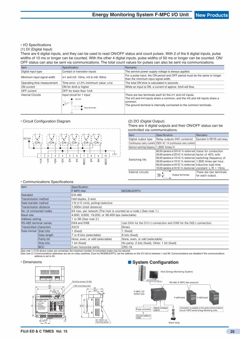
• I/O Specifi cations(1) DI (Digital Input)There are 6 digital inputs, and they can be used to read ON/OFF status and count pulses. With 2 of the 6 digital inputs, pulse widths of 10 ms or longer can be counted. With the other 4 digital inputs, pulse widths of 50 ms or longer can be counted. ON/OFF status can also be sent via communications. The total count values for pulses can also be sent via communications.Item Specifi cation RemarksDigital input type Contact or transistor inputs The service power supply voltage is always applied.
Minimum input signal width in1 and in2: 10ms, in3 to in6: 50ms For a pulse input, the ON period and OFF period must be the same or longer than the minimum input signal width.
Operating time measurement Time error: ±1.0% (minimum value: ±1s) The total ON time is calculated in seconds.ON current ON for 4mA or higher While an input is ON, a current of approx. 5mA will fl ow.OFF current OFF for lower than 1mAInternal Circuits Input circuit for 1 input
DC12V
Input terminals
There are two terminals each for the in1 and in2 inputs.The in3 and in4 inputs share a common, and the in5 and in6 inputs share a common.The ground terminal is internally connected to the common terminals.
• Circuit Confi guration Diagram
DC12V
1
in1+
in1−
in2+
in2−
in3
in4
COM
in5
in6
COM
2 3 4 5 6 7 108 9
• Dimensions
Terminal screws: 25-M3
2-M4 mounting holes56
IEC 35mm rail mounting space
49.58
315.08
90100
70 4980
4
IN1+ IN1- IN2+ IN2- IN3+ IN4+COMTerSGDXBDXA IN5+ IN6+ COM
TRANSMITRECEIVE
POWERRUNERROR
RS-485
AC100-240VFGOUT2OUT1 OUT3 OUT4
5.08
F-MPC I/O
31
OFF
1OFF
1
6
901
456
9
543210
78
2378
00
System Confi guration
Host (Energy Monitoring System)
F-MPC04S F-MPC04S
F-MPC I/O DI/DO Unit
Alarm lamp
RS-485 (F-MPC-Net protocol)
Pulse converter
Account watthourmeter
Alarm contactsignal
Connection is possible on the same communications line as F-MPC-series Energy Monitoring Units.
• Communications Specifi cationsItem Specifi cation
F-MPC-Net MODBUS/RTUStandard EIA-485Transmission method Half-duplex, 2-wireData transfer method 1:N (I/O Unit), polling/selectiveTransmission distance 1,000m (total distance)No. of connected nodes 64 max. per network (The host is counted as a node.) (See note 1.)Baud rate 4,800, 9,600, 19,200, or 38,400 bps (selectable)Address setting 1 to 99 (See note 2.)RS-485 terminal names DXA and DXB Use DXA for the D1(+) connection and DXB for the D0(-) connection.Transmitted characters ASCII BinaryData format Start bits 1 (fi xed) 1 (fi xed)
Data length 7 or 8 bits (selectable) 8 bits (fi xed)Parity bit None, even, or odd (selectable) None, even, or odd (selectable)Stop bits 1 bit (fi xed) No parity: 2 bits (fi xed), Other: 1 bit (fi xed)BCC Even horizontal parity CRC-16
(See note 1.) If 32 device nodes are connected, the maximum number of connected nodes may be reduced.(See note 2.) Communications addresses are set on rotary switches. Even for MODBUS/RTU, set the address on the I/O Unit to between 1 and 99. Communications are disabled if the communications
address is set to 00.
(2) DO (Digital Output)There are 4 digital outputs and their ON/OFF status can be controlled via communications.Item Specifi cation RemarksDigital output type Relay outputs (NO contacts) Equivalent to RB105 card relays.Continuous carry current 250V AC 1A (continuous carry current)Maximum switching frequency 1,800 times/h
Switching life
600,000 operations at 220V AC 1A, resistive load200,000 operations at 220V AC 1A, inductive load900,000 operations at 110V AC 1A, resistive load300,000 operations at 110V AC 1A, inductive load600,000 operations at 24V DC 1A, resistive load120,000 operations at 24V DC 1A, inductive load
Value for conduction factor of 40% with switching frequency of 1,800 times per hour.Inductive load time constant: L/R = 15ms
Internal circuitsOutput terminals
There are two terminals for each output.

FUJI ED & C TIMES Vol. 15
New ProductsNew Products
26
Split-type Current TransformersCC2D
Lineup Includes New 100A and 800A CTs for the F-MPC.
FeaturesTogether with previous 5A, 50A, 200A, and 400A CTs, the six Types make it even easier to handle system needs.Special specifications just for the Fuji F-MPC-series Energy Monitoring Units.• Clamp construction for easy installation.• Large K to L indications to easily identify the primary
conductor direction.• Built-in clamping diode. The CT will not burn out even if the
secondary circuit is open.
Types, Ratings, and SpecificationsSeries Type Rated primary
current [A]Rated secondary current [A]
Hole diameter
Rated frequency [Hz]
Overcurrent resistance
Rated load Dielectric strength
Connection Mass [g]
F-MPC CC2D71-1004 100 33.33mA 16 dia. 50/60 1.0 In continuous
11.1mVA, load resistance: 10Ω
200V AC/1 min (between core and output)
Heat-resistant vinyl cable, AWG22×1,000mm included
Approx. 80
CC2D52-8009 800 133.3mA 60 dia. 50/60 40 In continuous
0.177mVA, load resistance: 10Ω
200V AC/1 min (between core and output)
Heat-resistant vinyl cable, AWG22×1,000mm included
Approx. 500
Note: Confirm the specifications of the F-MPC with which the CT is to be used.
PerformanceSeries Type Relative phase
difference (at 25°C)Rated load Dielectric strength Connection Ambient operating
conditionsF-MPC CC2D71-1004 ±1.0%/In
±1.5%/0.2 In1±1°/In1±1.5°/0.2 In
500V DC/100MΩ min (between core and output lead)
7.5Vp built-in clamping diode
−20 to 75°C, 80% RH max. with no condensation
CC2D52-8009 ±1.0%/In±1.5%/0.3 In
±60 min/In±90 min/0.2In
500V DC/101MΩ min (between core and output lead)
3.0Vp built-in clamping diode
−20 to 75°C, 80% RH max. with no condensation
CC2D71-1004

FUJI ED & C TIMES Vol. 15
New Products
27
Split-type Current Transformers CC2D
Dimensions, mm • CC2D71
29
18.5L⬅K
K⬇L 31
45(
1000)
(8)
30
16 di
a.
(1.5) (1)
I (black)
AWG22
k (white)
Nameplate
• CC2D52
L⬅K
K⬇L
(1000) (28)
(8)
0.75mm2-2CWhite: K, Black: l
2565 62
115
dia.
42
Nameplate
60 dia.
FUJI ED & C TIMES Vol. 15
New ProductsNew Products
28
AC Power RegulatorsAPR-D Series
The APR-D Series is the successor to the APR-αB and APR-αC. A CPU has been mounted to greatly improve the functionality and performance of these space-saving, wire-reduction, low-cost AC Power Regulators.
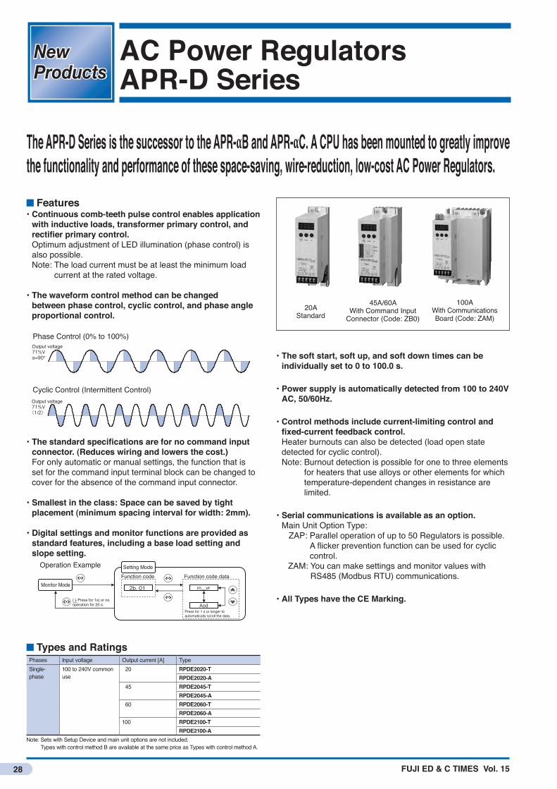
Features• Continuous comb-teeth pulse control enables application
with inductive loads, transformer primary control, and rectifier primary control.Optimum adjustment of LED illumination (phase control) is also possible. Note: The load current must be at least the minimum load
current at the rated voltage.
• The waveform control method can be changed between phase control, cyclic control, and phase angle proportional control.
Output voltage71%Vα=90°
Output voltage71%V(1/2)
Phase Control (0% to 100%)
Cyclic Control (Intermittent Control)
• The standard specifications are for no command input connector. (Reduces wiring and lowers the cost.) For only automatic or manual settings, the function that is set for the command input terminal block can be changed to cover for the absence of the command input connector.
• Smallest in the class: Space can be saved by tight placement (minimum spacing interval for width: 2mm).
• Digital settings and monitor functions are provided as standard features, including a base load setting and slope setting.
Monitor Mode 2b. 01 m_vr
Aod
Function code
(↓Press for 1s) or no operation for 20 s.
Press for 1 s or longer to automatically scroll the data.
Setting ModeFunction code data
Operation Example
• The soft start, soft up, and soft down times can be individually set to 0 to 100.0 s.
• Power supply is automatically detected from 100 to 240V AC, 50/60Hz.
• Control methods include current-limiting control and fixed-current feedback control. Heater burnouts can also be detected (load open state detected for cyclic control). Note: Burnout detection is possible for one to three elements
for heaters that use alloys or other elements for which temperature-dependent changes in resistance are limited.
• Serial communications is available as an option.Main Unit Option Type: ZAP: Parallel operation of up to 50 Regulators is possible.
A flicker prevention function can be used for cyclic control.
ZAM: You can make settings and monitor values with RS485 (Modbus RTU) communications.
• All Types have the CE Marking.
Types and RatingsPhases Input voltage Output current [A] TypeSingle-phase
100 to 240V common use
20 RPDE2020-TRPDE2020-A
45 RPDE2045-TRPDE2045-A
60 RPDE2060-TRPDE2060-A
100 RPDE2100-TRPDE2100-A
Note: Sets with Setup Device and main unit options are not included. Types with control method B are available at the same price as Types with control method A.
20AStandard
45A/60AWith Command Input
Connector (Code: ZB0)
100AWith Communications Board (Code: ZAM)

FUJI ED & C TIMES Vol. 15
New Products
29
AC Power Regulators APR-D Series
Dimensions• Refer to catalog number HS170.
SpecificationsItem SpecificationsType RPDE2020-□ RPDE2045-□ RPDE2060-□ RPDE2100-□
Inpu
ts Main circuit/control circuit Rated input voltage and frequency
Single-phase, 100 to 240V AC50Hz/60Hz (Automatically detected.)
Input voltage range ±10% of rated voltage (Performance is maintained.) (See note 1.)±15% of rated voltage (Operation is maintained.)
Input frequency range 50Hz/60Hz±2.5HzControl circuits Input capacity 15VA max.
Out
puts Rated current (at ambient temperature of 40ºC) [A] 20 45 60 100
Cooling method Natural coolingApplicable load Resistive load, inductive load, transformer primary control, or rectifier primary control (Only a resistive load (alloy) is supported for cyclic
control.)Minimum load current 0.5A (for 100% output at rated input voltage)Generation loss (at rated current) [W] 30 55 70 110
Cont
rols Waveform control method Single-phase thyristor pure reverse parallel connection
Phase control, cyclic control (intermittent), or phase angle proportional controlOutput voltage adjustable range 0% to 100% of main circuit power supply voltage (effective value) (excluding thyristor voltage drop)I/O characteristics Effective value linearity characteristic: ±3% FS for phase control (with resistive load and 10% to 90% set signal)
±5% FS for cyclic controlSet signal Automatic setting Current signal: 4 to 20mA DC (Zin = 100Ω)
Voltage signal: 0 to 5V DC, 1 to 5V DC (Zin = 11kΩ)SSC signal: 0V/12V DC (Zin = 11kΩ)
Manual setting External variable resistor: 1kΩ (B characteristic of 1/2W min.)Digital settings Front key entry (Direct drive is possible.)HIGH−LOW setting (two-position control)
Digital settings can be combined with an external variable resistor.Switching with external contact signals is possible with digital settings and the command input connector (main unit option).
Slope setting Setting range 0% to 100% of output voltageSetting device Voltage signal setting with digital setting, external 1kΩ variable resistor, or command circuit terminal (5V−M0) (Supported only for 1 to 5 V
DC.)A reverse slope characteristic is possible by combining with the base load setting.
Base load setting Setting range 0% to 100% or output voltageSetting device Digital setting
Soft start timeSoft up timeStart down time
Setting range Types with T or A control method: 0 to 100 sTypes with B control method: 0.5 to 100 s (See note 2.)
Setting device Digital setting. Each time is set individually.Feedback control method (phase control only) AC CLR (Types with A control method)
AC ACR + AC CLR (Types with A control method) (AC CLR is given priority in operation.)Manual or automatic selection signal No-voltage contacts
Commu
nication
s (Se
e note
4.) Parallel operation master/slaves Maximum number of nodes: 50, main unit option Type: ZAP (Not compatible with APR-N Series.)Network communications RS-485-compliant, 2-wire, half-duplex communications, start-stop synchronization, Modbus protocol; RTU-complaint communications,
maximum number of nodes: 31, main unit option Type: ZAM
Erro
r det
ectio
n an
d pr
otec
tion CPU memory error CPU memory errors are detected at startup.
Power supply errors An error is detected if the control power supply is not between 45 and 65Hz.No connection to automatic setting input No connection to a current signal (4 to 20mA DC) or voltage signal (1 to 5V DC) is detected if automatic setting is specified.No connection to manual setting input No connection to a manual setting device (external variable resistor) is detected if manual setting is specified.No connection to slope setting input No connection to a slope setting device (external variable resistor or 1 to 5V DC) is detected.Reversed phase detection Negative-phase sequences are detected for the main circuit power supply and control power supply (main unit option Type Z45 only).Data writing/setting errors Read/write errors are detected for EEPROM.Thyristor errors Thyristor short-circuits are detected with an internal CT (Types with A or B control method).Communications errors Data transmission error are detected for parallel operation or network communications (main unit option Type ZAP or ZAM)Current limit detection Load currents that exceed the CLR set value are detected. The phase angle is switched to reduce the load current to within the CLR set
value (Types with A or B control method).Heater burnout A burnout is detected if the APR output current goes below the burnout detection value (Types with A or B control method). (See note 3.)Alarm output Open collector, 24V DC/0.1A, 1 circuit
Ope
ratin
g en
viron
men
t Ambient temperature −10 to 55°C (Derate the load current against the rated current above 40°C and below 55°C.)Storage temperature −20 to 60°CAmbient humidity 5% to 95% RH (with no condensation)Others No corrosive gas (especially sulfidizing gas or ammonia gas), dust, or vibration. Indoors, altitude: 1,000 m max.
Insula
tion Dielectric strength (between main circuit and ground) 2,000V AC 1 minInsulation resistance (against ground) 10MΩ with 500V DC insulation resistance tester
Notes: 1) “Performance maintained” means that the specifications are met and operation is possible. “Operation maintained” means that components are not damaged and operation is possible. 2) The soft start, soft up, and soft down times for Types with a B control method will be invalid if they are shorter than the response speed of PI control.
This is because PI control is given priority over the soft start, soft up, and soft down times. 3) For cyclic control, an open load is detected. 4) Just one of the Communications Board can be installed at the factory.
FUJI ED & C TIMES Vol. 15
New ProductsNew Products
30
Three-phase Rail-mounting Power FiltersRNFTD and RNFDS Series
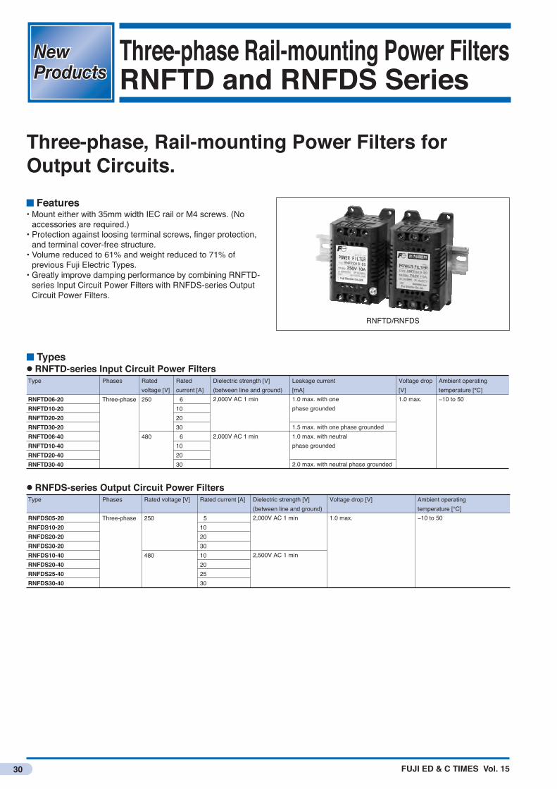
Three-phase, Rail-mounting Power Filters for Output Circuits.
Features• Mount either with 35mm width IEC rail or M4 screws. (No
accessories are required.)• Protection against loosing terminal screws, finger protection,
and terminal cover-free structure.• Volume reduced to 61% and weight reduced to 71% of
previous Fuji Electric Types.• Greatly improve damping performance by combining RNFTD-
series Input Circuit Power Filters with RNFDS-series Output Circuit Power Filters.
RNFTD/RNFDS
Types● RNFTD-series Input Circuit Power Filters
2,000V AC 1 min
2,000V AC 1 min
Type Phases Rated voltage [V]
Rated current [A]
Dielectric strength [V](between line and ground)
1.0 max. with onephase grounded
1.5 max. with one phase grounded1.0 max. with neutral phase grounded
2.0 max. with neutral phase grounded
Leakage current[mA]
1.0 max.
Voltage drop[V]
−10 to 50
Ambient operating temperature [ºC]
RNFTD06-20RNFTD10-20RNFTD20-20RNFTD30-20RNFTD06-40RNFTD10-40RNFTD20-40RNFTD30-40
250
480
6102030 6102030
Three-phase
● RNFDS-series Output Circuit Power Filters
2,000V AC 1 min
2,500V AC 1 min
Type Phases Rated voltage [V] Rated current [A] Dielectric strength [V](between line and ground)
1.0 max.
Voltage drop [V]
−10 to 50
Ambient operating temperature [°C]
RNFDS05-20RNFDS10-20RNFDS20-20RNFDS30-20RNFDS10-40RNFDS20-40RNFDS25-40RNFDS30-40
250
480
510203010202530
Three-phase

FUJI ED & C TIMES Vol. 15
New Products
31
Three-phase Rail-mounting Power Filters RNFTD and RNFDS Series
Dimensions, mmMain terminals, 6-M4
Mounting holes, 4-4.5 dia.
Ground terminal, M410
9.
7 16
16 64±3
50±1
Rat
ings
nam
epla
te
95±3
80±1106±1
116±1
74±3
60±1
.5
(Only the RNFTD has a ground terminal. The RNFDS does not have one.)
Type WeightRNFTD06-20 500g max.RNFTD10-20RNFTD20-20RNFTD30-20RNFTD06-40 600g max.RNFTD10-40RNFTD20-40RNFTD30-40RNFDS05-20 500g max.RNFDS10-20RNFDS20-20RNFDS30-20RNFDS05-40RNFDS10-40RNFDS20-40RNFDS25-40RNFDS30-40
Circuit Configurations● RNFTD-series Input Circuit Power Filters
Noise Damping Performance Examples● Dynamic Characteristics (Representative Type: RNFTD06-20)No Filter (Inverter Only)Noise Terminal Voltage (QP Value)
With RNFTD06-20 InsertedNoise Terminal Voltage (QP Value)
With RNFTD06-20 + RNFDS05-20 InsertedNoise Terminal Voltage (QP Value)
● Static Characteristics (Representative Type: RNFTD06-20)Normal Mode Common Mode
● RNFDS-series Output Circuit Power Filters
250V Type 480V Type
3LINE LOADL
L
L
CX CX CX
CX
CX Cy
Cy
Cy
CX
2
1
6
5
4
3LINE LOADL
L
L
Cy
Cy
Cy
CX
CX
CX
CX
CX
CX
2
1
6
5
4
L
L
L2
3LINE LOAD
1
5
6
4
405060708090
100110120 120
0.1 1 10 100Frequency [MHz]
[dBμV]
Frequency [MHz]
[dBμV]
Frequency [MHz]
[dBμV]
405060708090
100110
120
0.1 1 10 100405060708090
100110
0.1 1 10 100
IEC61800-3, C3(2nd Env) IEC61800-3, C3(2nd Env)
IEC61800-3,C3(2nd Env)
405060708090
100110120 120
0.1 1 10 100Frequency [MHz]
[dBμV]
Frequency [MHz]
[dBμV]
Frequency [MHz]
[dBμV]
405060708090
100110
120
0.1 1 10 100405060708090
100110
0.1 1 10 100
IEC61800-3, C3(2nd Env) IEC61800-3, C3(2nd Env)
IEC61800-3,C3(2nd Env)
405060708090
100110120 120
0.1 1 10 100Frequency [MHz]
[dBμV]
Frequency [MHz]
[dBμV]
Frequency [MHz]
[dBμV]
405060708090
100110
120
0.1 1 10 100405060708090
100110
0.1 1 10 100
IEC61800-3, C3(2nd Env) IEC61800-3, C3(2nd Env)
IEC61800-3,C3(2nd Env)
8070605040302010
0
0.1 1 10 100Frequency [MHz]
Damping amount [dB]
8070605040302010
0
0.1 1 10 100Frequency [MHz]
Damping amount [dB]
8070605040302010
0
0.1 1 10 100Frequency [MHz]
Damping amount [dB]
8070605040302010
0
0.1 1 10 100Frequency [MHz]
Damping amount [dB]

FUJI ED & C TIMES Vol. 15
New ProductsNew Products
32
Thermostat-type Temperature SwitchesPQ Series
Ideal for Temperature Control in Distribution Boards and Control Cabinets.• Turn space heaters ON and OFF to control in-panel temperatures. (NC contacts)• Turn ventilation fans ON and OFF to control in-panel temperatures. (NO contacts)
Features• Types available with either fixed temperatures or variable
temperatures.• Easy mounting to DIN rails.• Save energy and reduce CO2 emissions by controlling
temperatures.• A thermostat is used, so no power supply is required.• All Types are RoHS compliant (lead-free).
Type number nomenclature SpecificationsType PQ1 PQ2Maximum ratings 100 to 240V AC 3A (resistive load)
5 to 24V DC 1A (resistive load)Temperature error Operating temperature: ±4K *4
Reset temperature: ±4K −Differential *1 7k *2 4 to 7K *3ON resistance 1Ω max. (initial value)Durability 100,000 operationsAmbient operating temperature
−5 to 70°C
Ambient operating humidity
90% RH max.(with no condensation)
Mass 50g 70gNotes: *1) The difference between ON and OFF. *2) For an operating temperature of 40°C, the operating temperature is 40°C±4K and the
reset temperature is 33°C±4K (3K min.) *3) For an operating temperature of 60°C (it is a rough standard for other temperatures). *4) For the PQ2, this is the accuracy at 60°C (it is a rough standard for other temperatures).
PQ 1 B - 40Basic type
Operating temperature settingCode12
ModelFixed Variable
ContactCodeBA
ContactNC contactNO contact
Operating temperatureCode10203040506026
ModelFixed
Variable
Temprerature10°C*20°C*30°C*40°C*50°C*60°C*20 to 60°C
*: NC contact only

FUJI ED & C TIMES Vol. 15
New Products
33
Thermostat-type Temperature Switches PQ Series
Dimensions, mm● PQ1
94
25
57.6
37.3 41
98
Terminal cover
Slider
Terminal screws:8-M3.5
94
25
57.6
37.3 41
98
10m
ax.Terminal cover
Terminal screws:8-M3.5
Slider
①(Terminal
No.)
②
⑦(Terminal No.)
⑧
①
②
⑦
⑧
Mounting and RemovingMounting the Unit A. Hook the top of the unit onto the rail. B. Press in on the bottom of the unit.
←DIN rail
A
A
B
B
C
Top
Removing the Unit A. Pull down on the slider with a flat-blade screwdriver. B. Pull out on the unit to free the bottom. C. Remove the top of the unit from the rail.
←DIN rail
A
A
B
B
C
Top
Note) If the unit may move on the rail after it is mounted, we recommend that you use end clamps.
Connection Diagram (Terminals 1, 2, 7, and 8)
2 8
1 7Thermostat
Load
Note) The locations of the load and power supply are examples. (They could be reversed.)
Precautions• Use the unit at an installation temperature of between −5 and
70°C and at a humidity of 90% max.• Store the unit at a storage temperature of between −10 and
70°C and at a humidity of 60% max.• Use the unit in a location that is not subject to dust, dirt,
chemicals that adversely affect electric components, or harmful gases.
• Do not subject the unit to vibration or shock.
● PQ2
94
25
57.6
37.3 41
98
Terminal cover
Slider
Terminal screws:8-M3.5
94
25
57.6
37.3 41
98
10m
ax.Terminal cover
Terminal screws:8-M3.5
Slider
①(Terminal
No.)
②
⑦(Terminal No.)
⑧
①
②
⑦
⑧

FUJI ED & C TIMES Vol. 15
New ProductsNew Products
34
High-voltage Distribution Overcurrent RelaysQHA-OC1 and QHA-OC2
A New OCR with Enhanced Functionality.
Features• Stable protection with digital operation.• Easier coordinated protection with four time-lag
characteristics.• Three-step instantaneous characteristic for easier
coordinated operation with upstream and downstream protective devices.
• Constant monitoring of internal circuits and automatic inspection of output circuits.
• Numeric confirmation of operating status.• Mounting is compatible with previous QH Series.
Four Time-lag and Three Instantaneous Characteristics
QHA time lag
MCCB
DistributionOCR
Instantaneous3-step time lag
Digital Overcurrent Relay QHA-OC1
■LED DisplayOperating status display (Selected with knob.) • Instantaneous current • Time-lag current • Time-lag time■Set value display (when switching)■Error code display
Instantaneous characteristics■Setting can be changed from 2 steps to 3 steps.
Four time-lag characteristics■Extremely inverse time lag (EI)■Very inverse time lag (VI)■Inverse time lag (NI)■Definite time lag (DT)
QHA-OC1

FUJI ED & C TIMES Vol. 15
New Products
35
High-voltage Distribution Overcurrent Relays QHA-OC1 and QHA-OC2
External Wiring Diagram• QHA-OC1
CB
CT CT
X X XTC
52a
CTTC1R C2R C1T C2T T1 T2 a1 a2
DC power supply Alarm NO contacts(contact for 0.1 s)
AS
A
• QHA-OC2
X X XCB
CTCT
TC TC
CTT
A
AS
Alarm NO contacts(contact for 0.1 s)
C1R T1R C2T2R C1T T1T C2T2T a1 a2
Panel Drilling Dimensions
View from Front of Panel
124
124
2-7 dia.
142 dia.
Dimensions, mm
18 2-M6 mounting screws
137
dia.139
dia.
20.5 118
20
155
160
26
124
124
Types and RatingsType QHA-OC1 QHA-OC2Tripping method Shunt trip CT secondary current shuntRated current 5ARated frequency 50-60Hz
Tim
e-la
g el
emen
t Operation setting 3A, 3.5A, 4A, 4.5A, 5A, 6A, or lockTime-lag setting 0.25, 0.5, 1, 1.5, 2, 2.5, 3, 4, 5, 6, 7, 8, 10, 15, 20, or 30 (16 settings)Operating characteristics
Extremely inverse time lag (EI)Very inverse time lag (VI) SwitchableInverse time lag (NI)Definite time lag (DT)
Instan
taneo
us el
emen
t Operation setting 10A, 15A, 20A, 25A, 30A, 50A, 60A, 80A, or lock
Operating characteristics 2-step or 3-step (switchable)
Dis
play Operation display LED display (Lights green.)
Operating indicators R phase, T phase, and instantaneous (orange)Character display (red LEDs)
Start display ① 00Elapsed time ① 10, 20, 30, 40, 50, 60, 70, 80, or 90 (%)Current ② CT secondary current for R or T phase: 2.0 to 50 [A]Set values ③ Time-lag operation current, instantaneous time set value, and instantaneous operation currentSelf monitoring Error code display
Rese
tting
met
hod Output contacts Automatically reset when current drops.
Operating indicator Manually reset.
Output contacts Trip contacts: 1NO, Alarm contacts: 1NO
Conta
ct ca
pacit
y Tripping contactsShunt trip (T1,T2)Current trip (T1R, C2T2R) (T1T, C2T2T)
Making: 100V AC 10A (L/R = 7ms)220V DC 10A (L/R = 7ms)Breaking: 110V DC 1A (L/R = 7ms)220V AC 3.5A (cosφ = 0.4)
Trip contacts: 2NC, Alarm contacts: 1NOMaking: 110V AC 60A(Depends on CT’s load VA.)
Alarm contacts(a1, a2)
24V DC 2A (125V DC 30W max.) (L/R = 7ms)AC100V 2A (250V AC 220VA) (cosφ=0.4)
Consumed VA 5VA (at 5A)Standards JIS C 4602: Overcurent Relays for 6.6kV ReceivingMass 1kgNotes ① Displayed when the display knob is set to the elapsed time, R-phase elapsed time, or
T-phase elapsed time. ② Displayed when the display knob is set to the current, R-phase current, or T-phase
current. ③ Displayed when the display knob is set to the instantaneous current, time-lag current, or
instantaneous time. Also displayed for approx. 2 seconds for each setting.

FUJI ED & C TIMES Vol. 15
N o t i c eN o t i c e
36
Features• G-TWIN-series 125−250AF Short Terminal Covers• Mount the covers to increase the range of insulation
protection on the front. * The protection ranges for the wire insertion section and
from the back are the same as before.
Moded Cased Circuit Breakers and Earth Leakage Circuit BreakersMarketing of G-TWIN-series IP-reinforced Terminal Covers
Types
BW9BTCA - S 3 W P20IP-reinforced Type designationColor (W = Grey, Blank = Transparent)Number of poles (2 to 4)Length (S = short)Basic Type number
TypesFrame NO. of poles Terminal cover Type
Transparent Grey125AF 2 BW9BTCA-S2P20 BW9BTCA-S2WP20
3 BW9BTCA-S3P20 BW9BTCA-S3WP204 BW9BTCA-S4P20 BW9BTCA-S4WP20
250AF 3 BW9BTGA-S3P20 BW9BTGA-S3WP204 BW9BTGA-S4P20 BW9BTGA-S4WP20
Date of Market ReleaseOctober 2011
<Current Types>
<New Types>

FUJI ED & C TIMES Vol. 15
Modified ProductsModified Products
37
Changed Types
Applicable Types and Specific ChangesAsk your Fuji Electric sales representative for more detailed information.Product Series and Type Changed part Specific change Change dateMagnetic Contactors or Magnetic Motor Starters
SC-03 to SC-N14, FC Series Label Changed CCC energy-saving label. August 2011SC, SW-03 to SW-5-1 Main terminals Raised main terminal base level. February 2012SC and SW-N4 to SW-N7 Fixed contact block Added notch to fixed contact block. February 2012SC-N16 Some of the
configuration partsShapes November 2011
NEO SC Series Terminal cover screws Color July 2011New SC-series Mechanical-latching Types
Operating indicator Color July 2011
New SC-series General-purpose Special Types
Nameplate Changed nameplate. July 2011
Some NEO SC-series and SB-series Types
Fixed contact block Changed to non-plated contact block. September 2011
Some Types of New SC-series Thermal Overload Relays
Nameplate Changed nameplate. April 2012Reset releases Added mounting bracket (accompanying SK marketing). February 2012
FC-0S Contact support Changed color. February 2012FC and SJ Series CCC Mark Changed to printing the CCC Mark. September 2011SJ-0G and SJ-06G (including SW)
Main contacts Changed shape. April 2011
Some Types of Surge Absorber Units
Indications Added manufacturing location. January 2012
Manual Motor Starters BM3 Series Power supply input terminal block
Power supply input terminals January 2012
Optional Products for BM3 Series
Packaging labels and nameplates
Contents June 2011
BM3R and BM3V Nameplate Contents October 2011BM3 Series UL nameplate Contents February 2012
Automatic Breakers and Earth Leakage Circuit Breakers
G-TWIN 400AF Auxiliary nameplate Changed dimensions. April 2011Power Controller for G-TWIN 400-800AF
Wiring outlet Wiring outlet position September 2011
G-TWIN-series and L-series Rain-proof Steel Boxes for 100AF and Smaller Types
Packaging Packaging specifications September 2011
G-TWIN Economic Types of 100AF or Smaller
Studs for rear mounting (X Types) and flush-mounting (E Types) Types
Stud shape February 2011
G-TWIN 630AF and 800AF Terminal cover Shape May 2011G-TWIN Global Types, 50AF and 100AF
Precautions nameplate Contents February 2012
Q2 Handle Key Lock Device, Plate Type for G-TWIN 400AF to 800AF
Set screws Shape December 2011
Solid-state Circuit Breakers Accessory lead wire Color July 201150AF and 100AF Earth Leakage Automatic Breaker
Earth Leakage indications
Changed parts. April 2012
V-Type External Operation Handle Extension Shaft
Set screws Set screw length April 2011
N- and V-Type External Control Handle
Structure Changed structure. June 2011
G-TWIN Global Types Nameplate and operating instructions
Nameplate printing method and operating instruction languages
December 2011
Build-in Earth Leakage Circuit Breakers
Nameplate Changed nameplate (changed PSE mark). March 2011
Electric Work Automatic Breaker
Nameplate Changed nameplate (changed PSE mark). March 2011
G-TWIN 100AF and Smaller Types for Transformer Primary
Nameplate Contents July 2011
Earth Leakage Protective Relays
EL Types Main unit case Changed material of main unit case. February 2012
Circuit Protectors CP-E Types Ratings nameplate Changed design. May 2012CP-F, CP-E, CP-V, CP-P, and CP-B Types
Contents June 2011

Modified Products
38 FUJI ED & C TIMES Vol. 15
Product Series and Type Changed part Specific change Change dateLow-voltage Fuses Fuse Holders for Indicator
FusesPrinting of lot number Ink color January 2012
Plug Fuses Protective cover for charging section
Height and logo mark May 2011
CR Fuses Indications Rated current and lot indication method August 2011Command Switches AH08-125 Series LED lamp Shape and color September 2011
AR22, DR22, AR30, DR30, AM22, DM22, AG28, and DG28 Series
Transformer Unit Company logo and part shape March 2012
AH25 series LED globe (green) Appearance June 2011AG22, AG23, AG225, AH164, AH165, AH165-2, AH16P, AH16P-2, AH22P, and AH225 Series
Contact Unit Changed. April 2012
Selector Switches (Some Types)
Stopper Changed color. February 2012
Command Switches and Square Indicators
LED lamp Changed Y color specification. April 2011
Multi Display Lights AP30F and AP40F LED (pure white) Brightness and color April 2012AP30F and AF41F Special Unit Deleted flicker and Constant-voltage Unit specifications. July 2011
Control Relays Types with 24V DC Rating Coil Changed color of coil insulation tape. February 2011HH2□ Types (Some Types) Surge-absorbing diode Changed mounting structure. April 2012HH64-series Power Relays Stamp Added contents to ratings stamp. November 2011
Timers MS4S (Some Types) Output contacts Changed electrical durability. January 2012Sockets for MS4S Terminal section Appearance May 2012ST7P Series Socket packaging box Changed displayed contents (removed UL contents). April 2012
Terminal Blocks AU-TW39 Main unit Changed color of acceptance stamp. November 2011LT5 Cap Changed text printing method. March 2012
FA Sensors PE-U Flat Inductive Proximity Switches
Case Displayed contents February 2012
Some Types of K244-series Limit Switches
Case Changed internal shape of case. February 2012
Cam Switches AK22 Main unit Changed logo mark. June 2011AK22-J Key Deleted logo mark from special key. June 2011AK22 Symbol plate Eliminated symbol plate standard accessory. July 2011AK22 Packaging specifications Deleted “No NP” from the packaging box accompanying
elimination of signal plate standard accessory.October 2011
RC310-1,2 Packaging specifications Deleted masking table (with small 10-position handle and microswitch)
November 2011
Energy Monitoring Equipment
F-MPC60B and F-MPC50 Series
Indicator LEDs Changed parts. March 2012
F-MPC Web Units Software and appearance
Version upgrade and RoHS compatibility May 2011
High-voltage Equipment Some Types of High-voltage Current-limiting Fuses
Packaging Changed packaging method. April 2012
Some Types of High-voltage Current-limiting Fuses
Main nameplate Changed lot and acceptance stamp indication. May 2012
Remote Power Controllers for High-voltage Disconnecting Switches
Electric motor Exterior color December 2011
HS Types Parts in main circuit connector
Changed surface treatment. April 2011
Square Current Transformers with Through Hole
CC3M□ Coating, nameplate, etc. Eliminated red coating and changed nameplate specifications and installation instructions.
January 2012

FUJI ED & C TIMES Vol. 15
Discontinued ProductsDiscontinued Products
39
Discontinued ProductsAsk your Fuji Electric sales representative for more detailed information.Product name and series Discontinued product Replacement Types Date of
discontinuationRemarks
Magnetic Contactors or Magnetic Motor Starters
SJ-series Magnetic Contactors and Switches SK Series September 2012SC-M-series Magnetic Contactors and Optional Products
SK Series September 2012
SZ-J□ Operation Counters – July 2012Some Types of SRC-series Magnetic Contactors and Switches
SK Series September 2012
Auxiliary Relays SRC(WRC)50-2F/X Contactor-type Auxiliary Relays
SRC(WRC) 50-2U/X March 2012
Solid-state Contactors Reversible Unit-type SSCs None September 2011SY-P-A1 Power Units for SSCs None September 2011
Molded Cased Circuit Breakers and Earth Leakage Circuit Breakers
1200AF-Type BU Breakers with UL and CSA Standard Certification
– April 2011
BU Breakers – March 2012DG33N-2E Equivalent product from another
companyMarch 2012
Command Switches Command Switch DR30B0 30-dia. Electromagnetic Buzzers
DR30B5 and DR30B6 Types (electronic sound)
December 2012
AG22- and AG23-series Square Command Switch Barriers (White)
Black and gray Types in the same series April 2012
Constant-voltage Units None August 2012Control Relays H35-7.5 Steel Socket Mounting Rails TH35-7.5AL (Aluminum Rail) July 2012Timers MS4SM-DB, MS4SA-DB, MS4SR-CE, and
MS4SR-CEN– November 2011
Terminal Blocks AYBN and AYBS TÜV Types November 2011Proximity Switches PE2-CTS Spatter-resistant Types – May 2012Limit Switches Al Series (Metal Types) – March 2011AS-i AS-i (Slave) AS-i Safety Accessory Gateway – September 2012Transducers Some L, C, S, WH1, WH7, and WH9-series Types January 2012Energy Monitoring Equipment
Some F-MPC60B-series Types (UM40*) March 2011
AC Power Regulators RPBE and RPCE March 2012Control Power Transformers
Some CU4 Types December 2011CU5 December 2011

Information in this catalog is subject to change without notice.
5-7, Nihonbashi Odemma-cho, Chuo-ku, Tokyo, 103-0011, Japan
URL http://www.fujielectric.co.jp/fcs/eng
Safety Considerations• Operate (keep) in the environment specified in the operating instructions and manual. High temperature, high humidity, condensation, dust,
corrosive gases, oil, organic solvents, excessive vibration or shock might cause electric shock, fire, erratic operation or failure.• For safe operation, before using the product read the instruction manual or user manual that comes with the product carefully or consult the
Fuji sales representative from which you purchased the product.• Products introduced in this catalog have not been designed or manufactured for such applications in a system or equipment that will affect
human bodies or lives.• Customers, who want to use the products introduced in this catalog for special systems or devices such as for atomic-energy control,
aerospace use, medical use, passenger vehicle, and traffic control, are requested to consult with Fuji Electric FA.• Customers are requested to prepare safety measures when they apply the products introduced in this catalog to such systems or facilities
that will affect human lives or cause severe damage to property if the products become faulty.• For safe operation, wiring should be conducted only by qualified engineers who have sufficient technical knowledge about electrical work or
wiring.• Follow the regulations of industrial wastes when the product is to be discarded.• For further questions, please contact your Fuji sales representative or Fuji Electric FA.
2013-04 PDF FOLS TIME015