front suspension redo (huge) - dynv12.dyndns.org/bmw/bmw 8 (e31)/miscellaneous/e31faq...loosen the...
TRANSCRIPT

Front
Suspension
Redo
Message:
First, thanks to all the previous posters for guidance in my doing the suspension. As thanks,
here’s the ‘updated’ document for doing the front suspension.
Procedure:
While there was no reason to take the strut assembly completely off the car, we decided to
remove and replace the control arm bushings. The reassembly of the shocks, springs and camber
plates to the strut went so much easier off the car.
Raise then support the front of the car. This shows how to safely use a hydraulic jack at the
jack point as well as have security with a jack stand.
Loosen the 22 mm nut on the top of the shock absorber piston before removing the strut
assembly from the car. This nut is under the plastic cap at the top of the shock tower. Use a

Loosen the 22 mm nut on the top of the shock absorber piston before removing the strut
assembly from the car. This nut is under the plastic cap at the top of the shock tower. Use a
breaker bar on the hex socket (6 mm Allen hex) and break loose the 22 mm Nyloc nut with a
gooseneck or box end wrench. When loosened it will be much easier to remove the strut bearing
assembly on the bench.
Loosen the three nearby 13 mm flanged retaining nuts that hold the strut bearing assembly to
the shock tower.
Remove the wheels.
Disconnect the existing left and right end links. New stock swing supports were being installed,
so the upper end link bolts where they attach to the hub/shock hub assembly were removed.
Remove the top 17 mm nuts on the sway bar links. Use a skinny 16 mm open-end wrench (5/8”) on
the inner flats to keep the ball from turning.
Detach brake wear sensors just behind the top of the backing plates; seen here with the green
wire at the top of the picture.
Remove the two 19 mm caliper carrier bolts. Pull the caliper away from the brake disk and
support it up under the wheel well so that there is no stress on the brake line.

Remove the 5 mm hex screw that holds the 324x30 mm rotor in place.
Set aside the brake disk.
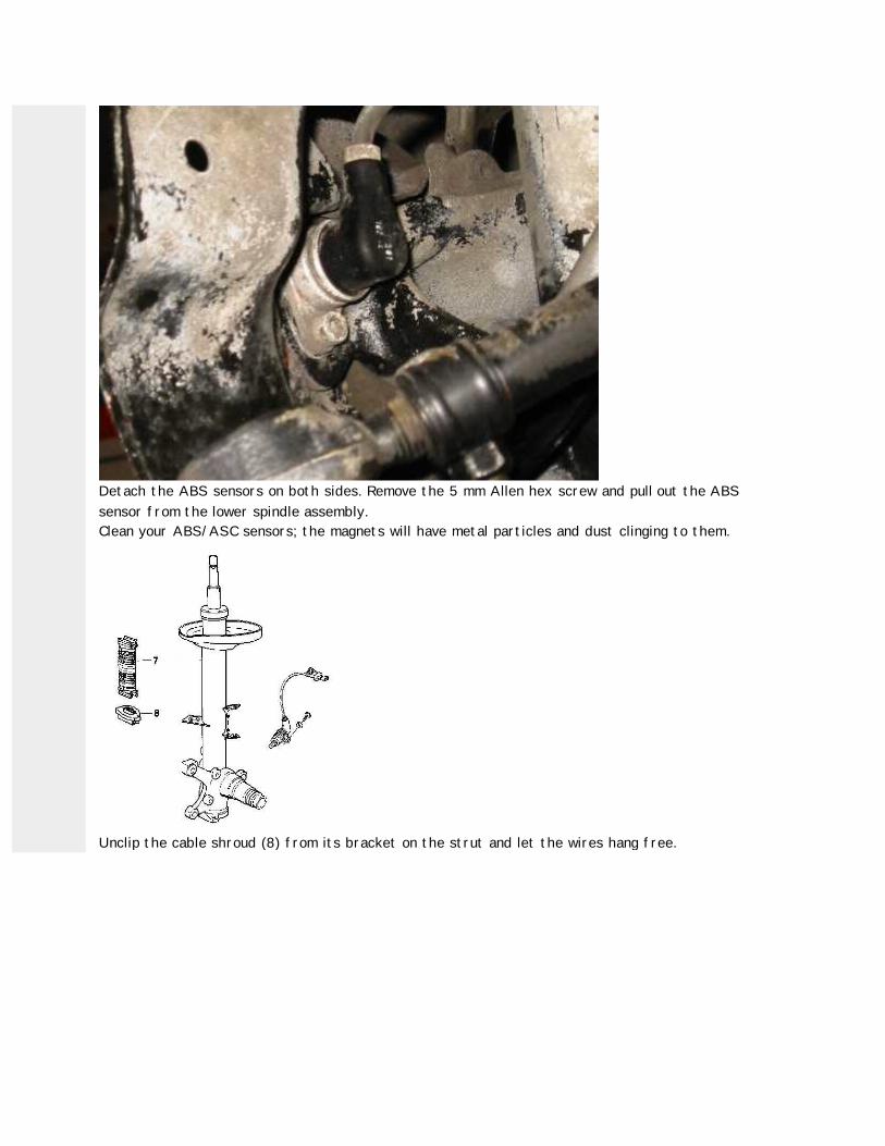
Detach the ABS sensors on both sides. Remove the 5 mm Allen hex screw and pull out the ABS
sensor from the lower spindle assembly.
Clean your ABS/ASC sensors; the magnets will have metal particles and dust clinging to them.
Unclip the cable shroud (8) from its bracket on the strut and let the wires hang free.

Check the condition of these:
1. Lower control arm (aluminum),
2. Upper control or thrust arm,
3. Tie rod.
See if any of them, particularly the upper control arm bushings, need to be replaced. Replace
any other worn suspension/steering parts (tie rod ends, idler arm, track rod or bushings).
Now I was ready to remove the strut. Initially, I thought I would just do the bushings for the
thrust arms while they were on the car. That plan changes later.
I supported the strut with a floor jack then removed the three 13 mm flanged nuts holding the
spring perch to the shock tower. Slowly release the floor jack to lower it, guiding the strut
down until it is clear, then placed it on a block.
You could use old towels to protect the wheel well paint in case the assembly gets away from
you.
Use the spring compressor to take the pressure off the top bearing. Follow the compressor
instructions carefully for safety. Span as many coils as you can. I went to AutoZone for these
spring compressors. They loan tools for up to a week free.

spring compressors. They loan tools for up to a week free.
When the pressure was off the bearing, I then removed the top Nyloc nut loosened previously
and removed the stopper, bearing, support, upper spring pad, spring, lower spring pad, bump
stop, and rubber boot.
Spray these threads of the collar nut with penetrating oil for days before working on this job.
The upper cap will come of easily. Use a plumber's pipe wrench to remove the collar nut. Mine
came of easily. See posts from ‘John in DC’ for tales of tragedy.
On a side note. The picture below shows two holes in the spring seat. I put bolts in these, then
used a long bar between them to use as a counterforce against the pipe wrench. You could use
one bolt in a hole and the strut tube as well for leverage.

After removing the collar nut, the insert assembly slipped out with a little effort. There is
about 1/2 pint of oil in the bottom of the strut tube that will spill when you remove the insert.
This oil must be removed before the Bilstein inserts can be installed. I used a MityVac to
remove most of the oil then, fashioned a large Q-tip out of a long dowel and a paper towel to
mop out the remaining oil at the bottom of the tube.
The bearing at the top of the strut piston located up in the shock tower is designed in such a
way that it catches a lot of dirt in a circular moat. There are four small drain holes and over
time, they clog up. It cannot be disassembled or lubricated but give it a good cleaning.
Reassembly:
After about a week on the blocks, everything checked and all the oils changed, it was time to
get it back together. MWrench joined me for a day of fun.
Here’s the Bilstein strut inserted and tightened down. We decided to do the bushings on the
bench. We removed the strut assembly with the upper, lower control arms, pressed in new

Here’s the Bilstein strut inserted and tightened down. We decided to do the bushings on the
bench. We removed the strut assembly with the upper, lower control arms, pressed in new
bushings in the upper control arm. This was a lot easier to do with the strut assembly on the
bench.
It can’t be said enough. Make sure you have the Bilstein tool for tightening the collar nut
before you start this project.

Really make sure you have the Bilstein tool for tightening the collar nut before you start this
project. I did not, so after calling around we made one at the last minute using an old ½”
extension and the old collar nut. He sure makes a pretty weld.
The Bilstein insert is installed, the collar nut is then torqued There is black tape wrapped
around the piston of the strut to protect the surface. Use anti-seize on the strut tube's
threads (and elsewhere) but not where you use either a Nyloc nut or Loctite.
Here’s a tidy tool that MWrench brought with him. We were able to assemble everything
quickly, safely, and easily, after the new thrust bushing was installed. This picture shows

Here’s a tidy tool that MWrench brought with him. We were able to assemble everything
quickly, safely, and easily, after the new thrust bushing was installed. This picture shows
camber plate, H&R springs installed over the Bilstein strut.
It is very important that when the new or rebuilt arm is re-installed that the bolt on the
chassis end not be tightened up. Only after the car is lowered back on to the ground are the
bolts tightened to 91 ft lbs. This is so the bushing is not under torque when at rest.
Here’s a cautionary note about camber plates. While other documents detail the installation of
camber plates, you must prepare the stopper washers for the reduced clearance. If not, then
the stopper washer will definitely rub the sheet metal. It is possibly due to the excessive
flexing of the upper strut mount in this case caused by the Bilstein. These pictures were taken
only days after the install, so the damage happens quickly.
The offset caused by the camber plate will cause the stopper washer to rub against the sheet
metal. This happened within days of the installation.

metal. This happened within days of the installation.
A simple fix is to reduce the size of the washer by machining off the top of the washer to
effectively reduce that diameter. The one on the right is original.
This shows the modified stopper washer back in. The damage caused by the old washer can be
seen above the rubber. The rubber portion still is in contact with the sheet metal, but the is no
metal contact anymore.

A fresh coat of paint completes the repair. Looks good again, but I wonder how long the front
strut supports are going to last... Perhaps those out there with the H&R/Bilstein/KBar setup
can give some feedback on this.
Front K-Bars Installation Procedure.
There is a bunch of information out there on this as well as Greg’s installation procedures. This
is just our chronicle of the events.
From previous posts:
With the upgraded loads from the K-Bars you should go through all moving suspension pieces for
wear. The car will see increases on the order of 100% front in suspension loads from the stiffer
bars holding it flat in corners. Aside from shocks and springs, on the short list are the front
control and thrust arm bushings; they normally need replacement about every 30k miles. Front
wheel bearings should be checked. Stock end links, if original, the increased loads would warrant
changing for new ones.
Ok then, we did this with the car’s front end supported and wheels removed.
Noted the position and orientation of the existing bar as installed.
Disconnected the existing left and right end links.
New stock swing supports were being installed, so we removed the upper end link bolts where
they attach to the hub/shock hub assembly.
We then undid the four bracket bolts securing the bushings, left and right side. The bar then
was lowered free from the car.

Shown is the old bar with the old end links. Lay the new bar in the correct orientation with the
old bar adjacent. Mark the new bar support locations by laying them together for comparison.
Slip the two rubber sway bar bushings over the bar, with the rounded side facing down. Next,
install the steel mounting brackets (stabilizer supports) over the rubber bushings. A little soapy
solution on the parts helped things slip into place. Don’t use petroleum-based lubricants. Once
everything is in place, hold the bar against the mounting points, and install the four securing
bolts. Note that the slit in this rubber is facing the stabilizer support. We’ll come back to that
later.
End Link Installation.
Make sure that the front suspension is easily loaded (both sides evenly compressed). If not, it
will be difficult to slide the connecting bolts through the sway bar end holes. I decided to stay
on the weakest settings for now. Perhaps later, after I get used to the new feel, I’ll take it up a
notch. Again, Attach the top 17 mm nuts on the sway bar links. Use a skinny 16 mm open-end
wrench (5/8”) on the inner flats to keep the ball from turning.
For the front stock swing supports, I replaced the four M10 self-locking hex nuts (07 12 9 964
672). Torque the securing nuts to 35 ft-lbs.
Torque everything to specifications and have an alignment done once the springs have had some
time to settle. Settle-in time is especially important if you've swapped in new springs as part of
the process.
According to the footnote on the Bilstein application page original bump stops and protective
boots must be used. No bump stop is needed for the fronts, original bump stops only on the
rears. Is there a smaller BMW bump stop to replace the stock bump stop?
A week later I had the alignment done. Here are the results for the front. The camber plates
added about ½” to the toe-in.

A week later I had the alignment done. Here are the results for the front. The camber plates
added about ½” to the toe-in.
Ok, that’s it. I’ll stop here and do the write up for the rears on another post. Then finally, the
third in the series will be comparisons I have noticed about my car in the last month after the
change. Hopefully some hard hitting data. The stuff you want to hear about, then again, maybe
not.