from the i.a.d.d. and dieinfo tech notes
TRANSCRIPT
How to Calibrate the Platen Press for Optimal Diecutting Performance
Tech NotesFor Diemaking and Diecutting
From the I.A.D.D. and DieInfo
TN-0002August, 2002
The widespread success and acceptance of this technique is ample evidence of its importance in platen diecutting; however, there are 10 reasons you should footprint each press. The measur-able benefits include:
Ô Higher quality, with greater diecut part consistency & repeatability.
Ô Simpler and faster press cutting make-ready and changeover.
Ô Faster press speed, with reduced stoppages and non-productive time.
Ô Minimal patch-up, with less cutting variation, and lower waste.
Ô The elimination of dust, loose fiber, flaking, and cutting variation.
Ô Doubling the life of the die and the counter/matrix tools.
Ô Better sheet-control with less and smaller nicks.
Ô Increased efficiency with a lower cost of manufacturing.
Ô A reduction in the complexity and the stress of diecutting.
Ô Enabling the seamless transfer of jobs from one press to another.

How to Calibrate the Platen Press for Optimal Diecutting Performance
2 • Tech Notes
Brainstorming, Notes & Ideas“Many ideas grow better when transplanted into another mind than in the one where they sprung up.” Oliver Wendell Holmes

How to Calibrate the Platen Press for Optimal Diecutting Performance
Tech Notes • 3
Introduction ...........................................................................................5
What is the Goal of Effective Platen Diecutting? ................................7
How Does Platen Diecutting Work? .....................................................9
Why are Traditional Methods of Press
Leveling Ineffective? ...........................................................................12
The Press Calibration Solution ..........................................................15
Designing & Fabricating the Calibrated
Press Mapping Die ..............................................................................16
On-Press Preparation .........................................................................19
The Mapping Procedure .....................................................................21
Creating the Footprint Underlay ........................................................22
Footprint Location Alternatives .........................................................24
Footprint Management:
New & Old Job Procedures ................................................................26
Test Die Storage ...................................................................................27
Tools & Materials ................................................................................28
Standard Operating Procedures .........................................................30
Summary .............................................................................................32
Table of Contents
How to Calibrate the Platen Diecutting Press, a “How-To Series”, is published by DieInfo, Inc. ©Copyright, DieInfo, Inc., 2002, All Rights Reserved. No part of this publication may be printed or otherwise reproduced without written permission from DieInfo.
NOTICE: The editors and publishers have endeavored to make this publication the most effective, up-to-date technical information published. All instructions, diagrams, and procedures have been checked for accuracy and ease of application; however, success and safety in the implementation of these techniques depend on individual precision, skill and caution. For this reason we cannot guarantee the results of any procedure, nor assume responsibility for any damage to property or injury to persons occasioned from execution of any procedure or technique. Persons do so entirely at their own risk.

How to Calibrate the Platen Press for Optimal Diecutting Performance
4 • Tech Notes
Kevin B Carey is the Technical Director of DieInfo and has been involved in converting, diecutting, diemaking, and related technology for more than 40 years.
Carey served a diemaking/diecutting apprenticeship in Europe, gaining experience as a Converting Master Craftsman, before becoming a trade union leader, a trainer, and a production supervisor. In 1979 he formed Lasercomb America and led it as President/CEO to become the leading innovator in commercial diemaking, CAD-CAM systems and related technology.
The experience gained in implementing progressive technology induced Kevin to change career paths in 1990 when he formed a training and process development orga-nization dedicated to eduction in converting. First as a consultant, then as a trainer, a lecturer, and finally an editor, the company began to define the problem of performance in converting manu-facturing and to develop solutions to solve problems and fill knowledge gaps. It was apparent during this time there was a poor understanding of the difference between training ad information and technical data management. Although poor performance is often seen as a training issue, it is more likely to be the absence of specific graphic information which can build confidence and competence in even the most inexperienced trainee.
This experience grew into DieInfo. publishing, consulting, training, auditing, and trade show organization, whose E-Business Technical Publishing and Information Center is on-line at www.dieinfo.com.
Kevin has given hundreds of presentations to the converting industry in Europe, the Pacific Rim, and North and South America. He is the editor of DieInfo magazine and is a frequent con-tributor to leading industry publications. DieInfo is an IADD sponsor company and Carey has served as an Association Director in addition to his recognition as the Diemaker and Diecutter of the year in 1986.
Carey is available for in-house training and consulting and can be reached at [email protected] or by calling 1.360.385.4214.
The Author
The IADD is a not-for-profit international trade association serving diecutters, diemakers, and industry suppliers worldwide. The Association serves as a worldwide leader and catalyst in inspiring industry success and the ultimate benefits to society that the industry provides. The vi-sion of the IADD is to be the definitive resource for the diecutting converting industry, bringing together and serving people who convert soft to semi-rigid materials into various cut parts. By sharing collective knowledge, expertise and information, the IADD leads and stimulates creativ-ity and innovation, provides opportunities for professional growth, serves the diverse needs of all industries engaged in diecutting and demonstrates commitment to ensuring progress through participation.
IADD provides conferences, educational and training programs, networking opportunities, a monthly magazine, technical articles, regional chapter meetings, publications and training manuals, recommended specifications, videos and surveys. IADD also presents the Diecutting Odyssey, a unique trade show and innovative concept in technical training featuring a hands-on Techshop™where training programs come alive in an actual working diemaking and diecutting facility inside the exhibit area.
Visit www.iadd.org or call 1-815-455-7519 for more information about IADD.
The International Association of Diecutting and Diemaking
How to Calibrate the Platen Press for Optimal Diecutting Performance
Tech Notes • 5
There are 10 reasons you should footprint each press. The real benefits include:
Ô Higher quality, with greater diecut part consistency & repeatability.
Ô Simpler and faster press cutting make-ready and changeover.
Ô Faster press speed, with reduced stoppages and non-productive time.
Ô Minimal patch-up, with less cutting variation, and lower waste.
Ô The elimination of dust, loose fiber, flaking, and cutting variation.
Ô Doubling the life of the die and the counter/matrix tools.
Ô Better sheet-control with less and smaller nicks.
Ô Increased efficiency with a lower cost of manufacturing.
Ô A reduction in the complexity and the stress of diecutting.
Ô Enabling the seamless transfer of jobs from one press to another.
Press Footprinting is a non-complex method of simplifying the task of achieving a fast, stable cutting make-ready. It is of course, important to understand the underlying principles, to ensure the procedure is applied effectively. Like you I am constantly searching for better, faster, and simpler methods. If you have any questions, suggestions, or recommendations about press level-ing, I will be delighted to hear from you. I can be contacted at 1-360-385-4214, or by email at [email protected]. Good luck!
IntroductionLeveling the cutting impression in the traditional manner is an important part of platen press
make-ready and changeover. The problem the diecutting operator faces is the procedure is far too complex, it is unpredictable, and it damages the tools and press components. The resulting diecut parts are variable in quality, the degree of waste generated is unacceptable, and the time lost in this “black-art” raises costs and lowers profit.
Fortunately, there is a method of press leveling and press calibration, which is based upon solid science and is proven effective in every application it has been used in. It is a simple, fast, and effective method of press and tool stabilization, which will eliminate much of the il-logical patch-up or shimming of tools.
Press Footprint or the calibration of the diecutter is a key, foundation discipline, which is the missing activity, which undermines every action taken in a traditional make-ready. This pam-phlet is designed to teach the diecutter and diemaker how to map and measure the press and to create a permanent pressure compensation foil underlay.

How to Calibrate the Platen Press for Optimal Diecutting Performance
6 • Tech Notes
Brainstorming, Notes & Ideas“Many ideas grow better when transplanted into another mind than in the one where they sprung up.” Oliver Wendell Holmes

How to Calibrate the Platen Press for Optimal Diecutting Performance
Tech Notes • 7
What is the Goal of Effective Platen Diecutting?
It is important to recognise diecutting is a manufacturing process, and the primary goal is to stamp multiple parts, with each and every diecut part conforming precisely to the customer approved specifi-cation. See illustration A. It is vital each component is repeatable in terms of dimensions, performance characteristics, and graphic registration, from die cavity to die cavity and from the first impression to the last part diecut. The process of converting a sheet or a web of material into a product or a component of higher value is based upon the potential consistency inherent to this form of volume manufactur-ing.
The diecutting converting machine is a production line, which consists of a sequential alignment of separate but integrated and synchronized processing units. Sheets of material are flowed in a continuous stream into and registered to each reciprocating male and female tool holder, which stamp and convert, strip and remove internal waste, and blank and separate diecut product from the remaining waste material. See illustration B. This continuous process converts sheets of paper, paperboard, or fluted material into finished products or components,
which have a higher value than the original material.
After considering all of the customer needs and approving the final diecut part design, the diecutting manufacturer is seeking to create an ef-fective and an efficient system of stamping manu-
facturing. This generally requires lowering operating costs, by minimizing waste in terms of time and material, and by turning
each order around as quickly as possible. In simple diecutting terms this is defined as, “Selling
the First Impression!”
To many professionals this may seem an impos-sible goal; however, how many impressions are re-
quired to approve a diecut sheet? Five, ten, twenty, or is each production cycle a continuous series of adjustments to the steel rule die and the other tools? This is a very important measurement of productive efficiency in the diecutting process. What is the average number of sheets used in your opera-tion to get an approval to begin production?
Press Footprinting or platen calibration is a proven technique, which will eliminate many of those variables, such as excessive patch-up, see illustration C, which undermine current efforts to achieve a low pressure, 100% kiss cutting impression. Using current methods the operator is continuously compensating for and struggling with the same variables from job to job. While the design, the layout, and the material may change, the underlying unevenness of the platen mechanism is a constant source of variation. The technique of press footprinting will simplify the task of setting an even cutting impression, by creating a permanent underlay to level the cutting surface.
Production Record
Quality & Folding Performance

How to Calibrate the Platen Press for Optimal Diecutting Performance
8 • Tech Notes
There are ten primary productive goals in diecutting, which appropriately begin with Safety and end with Education. It is important to recognize that each production cycle is a test of tool parameters, of methods, and of materials, and this research effort should be continuously converted into new knowledge, better techniques, and more effective ways to diecut.
Press Footprinting is merely the first step in a series of innovative methods and more effective practices, which will reduce the complexity of diecutting, and improve the efficiency of the converting process. The ten goals of diecutting are:
✱ Creating and maintaining a Safe System of Working.
✱ Generating optimal part to part quality, consistency, and repeatability.
✱ The continuous search for the fastest, standardized method of press changeover.
✱ Generating a stable cutting impression to “Sell the First Impression.”
✱ Ensuring precision tool to tool integration and synchronization.
✱ Minimizing diecutting tool(s) and press component damage.
✱ Reducing press lost time and diecut material waste.
✱ Optimizing press speed and yield.
✱ Working together as a team to share knowledge, skill, and experience.
✱ Close the education loop by continuously learning and applying new knowledge.
In general manufacturing of every type there is a universal mission statement which guides all activity. This guiding definition is, Safety-Speed-Quality-Cost. This simply means every procedure or change to existing practices must first be evaluated for the impact it has on safety, then upon the speed of execution, then upon the quality of the finished product, and finally upon the cost of manufacturing. See illustration D.
In “street terms” this is the familiar, Safer, Faster, Better, Cheaper! The goal of the diemaking and diecutting professional is to ensure an efficient and an effective diecutting
converting operation. (Notice how the illustration shows the mission statement as a closed loop of activity. This is intended to define this mission statement
as a continuous effort to improve safety, to increase processing speed, to upgrade diecut part quality, and to reduce operating cost.)
Therefore, the first step in process improvement requires learning how to solve the perennial problem of cutting variation in platen diecutting. We
begin by gaining an understanding of how platen diecutting works, and how these principles impact and undermine our ability to achieve an effective and an ef-
ficient cutting make-ready?
D
How to Calibrate the Platen Press for Optimal Diecutting Performance
Tech Notes • 9
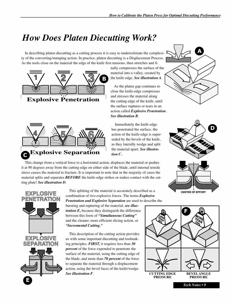
How Does Platen Diecutting Work?In describing platen diecutting as a cutting process it is easy to underestimate the complexi-
ty of the converting/stamping action. In practice, platen diecutting is a Displacement Process. As the tools close on the material the edge of the knife first tensions, then stretches and fi-
nally compresses the surface of the material into a valley, created by the knife edge. See illustration A.
As the platen gap continues to close the knife-edge compresses and stresses the material along the cutting edge of the knife, until the surface ruptures or tears in an action called Explosive Penetration. See illustration B.
Immediately the knife-edge has penetrated the surface, the action of the knife-edge is super-seded by the bevels of the knife, as they laterally wedge and split the material apart. See illustra-tion C.
This change from a vertical force to a horizontal action, displaces the material or pushes it at 90 degrees away from the cutting edge on either side of the blade, until internal tensile stress causes the material to fracture. It is important to note that in the majority of cases the material splits and separates BEFORE the knife-edge strikes or makes contact with the cut-ting plate! See illustration D.
This splitting of the material is accurately described as a combination of two explosive forces. The terms Explosive Penetration and Explosive Separation are used to describe the bursting and rupturing of the material, see illus-tration E, because they distinguish the difference between this form of “Simultaneous Cutting” and the cleaner, more efficient slicing action, or “Incremental Cutting.”
This description of the cutting action provides us with some important diecutting and toolmak-ing principles. FIRST, it requires less than 30 percent of the force expended to penetrate the surface of the material, using the cutting edge of the blade, and more than 70 percent of the force to separate the material through a displacement action, using the bevel faces of the knife/wedge. See illustration F.
E
Explosive Penetration
Explosive Separation
CUTTING EDGEPRESSURE
BEVEL ANGLEPRESSURE

How to Calibrate the Platen Press for Optimal Diecutting Performance
10 • Tech Notes
Clearly, the majority of pressure in diecutting is derived from the shape and bevel angles of the wedge or knife used to split the material apart. SECOND, as the bevel angle of the knife is increased, the amount of pressure required to diecut increases, and as the bevel angle of the knife is reduced, the amount of pressure required to diecut decreases. See illustration G.
THIRD, when using the same knife bevel angle to cut at right angles to the paperboard grain as opposed to cutting parallel to the paperboard grain, the necessity of tearing and breaking the fibers apart obviously gener-
ates greater resistance to compression and to splitting, and it requires more “pressure” to diecut. See illustration H.
FOURTH, as a knife penetrates deeper into the material the lateral push from both knife bevels is met with “increasing” resistance to splitting from the material, as the material is pushed to one side. See illustration I.
In a center bevel knife this lateral pressure/resistance is balanced on either side of the centerline formed by the cutting edge of the blade. See illustration J.
FIFTH, as parallel knives are brought closer to-gether the material in between the knives is forced to compress to absorb the displacement action from the facing inside knife bevels.
The material resists this compressive force, and particularly between the knives, where it has limited ability to get out of the way. As a result the closer the knife/bevels get together the higher the degree of pressure generated by diecutting. See illustration K.
This is called Inside/Outside Pressure in diecutting and this effect is most evident in examining how a one inch length of knife requires 300 pounds of pressure to diecut a material, and the same knife bent into a U shape requires 350 pounds of pressure to diecut the same material? See illustration L. (This is why narrow slots and small shapes require a seemingly disproportionate amount of pressure to diecut!)
This happens because the material trapped between the inner bevels of the “U” shape is resistant to lateral displacement compression and as a result the overall pressure required to diecut the shape increases dra-matically, even though the length of knife remains one inch long! The proximity of one knife to another is an important, yet consistently overlooked factor in platen diecutting.
L
LENGTH OF BOTHKNIVES = 1 INCH
“INSIDE/OUTSIDE”PRESSURE
300 lbs 350 lbs
GRAIN DIRECTION
25Tons
30Tons
40DegreeBevel
60DegreeBevel
50Tons30Tons

How to Calibrate the Platen Press for Optimal Diecutting Performance
Tech Notes • 11
SIXTH, although the term “pressure” is used in diecutting, the amount of force on each cutting knife is adjusted by changing the distance between the knife-edge and the anvil, or the “Platen Gap.” See illustration M. This is called “Z-Axis Control” in diecutting, and it represents the most important and the most difficult adjustment/setting in diecutting.
For example, if a die were cutting three different materials with very different densities, but with an identi-cal caliper or thickness, the pressure required to cut each material would vary enormously; however, the travel distance of the tool would remain constant. See illustration N.
SEVENTH, one of the key characteristics of platen diecutting is the draw, or tensile stress generated by the knife
as it penetrates a material, and “competes” with other knives, as they both pull material toward them in the initial phase of cutting. See illustration O.
This competition between various steel rule die components as they convert the material, is particularly evident when a cutting knife is parallel and close to a creasing rule. See illustration P.
Finally, all of these factors are combined to provide a basic formulation for calculat-ing pressure in platen diecutting. This states for every linear inch of knife in the die the blade requires 300 pounds of pressure to diecut, every linear inch of creasing rule requires 80 pounds of pressure to crease, and every square inch of ejection material requires twenty five pounds of pressure to compress the material. See illustration Q. This is clearly only a guideline as a varia-
tion in the density or the caliper of the material, or in the bevel angle of the knife or the durometer of the rubber would modify the calculation.
In practice this information can be used to pre-determine the pressure setting of the press in make-ready. This information is derived from the CAD CAM sys-tem which can convert the approved design and layout into a pressure calculation and initial make-ready pressure setting! To optimize tool design and to simplify achieving a 100% kiss cut impression, with minimal cutting blade edge damage; these principles should be applied to the process. Unfortunately, the practices and methods used to specify and fabricate tools and to set the correct on-press cutting impression are seriously flawed.
M
KNIFE300 lbs
CREASE80 lbs
RUBBER25 lbs
PRESS SHUTHEIGHT
As the density of material increases theresistance or “Pressure” to diecut increases.
However, the “Travel Distance” or the distance the bladetravels to cut through each material is identical!
How to Calibrate the Platen Press for Optimal Diecutting Performance
12 • Tech Notes
Why are Traditional Methods of Press Leveling Ineffective?
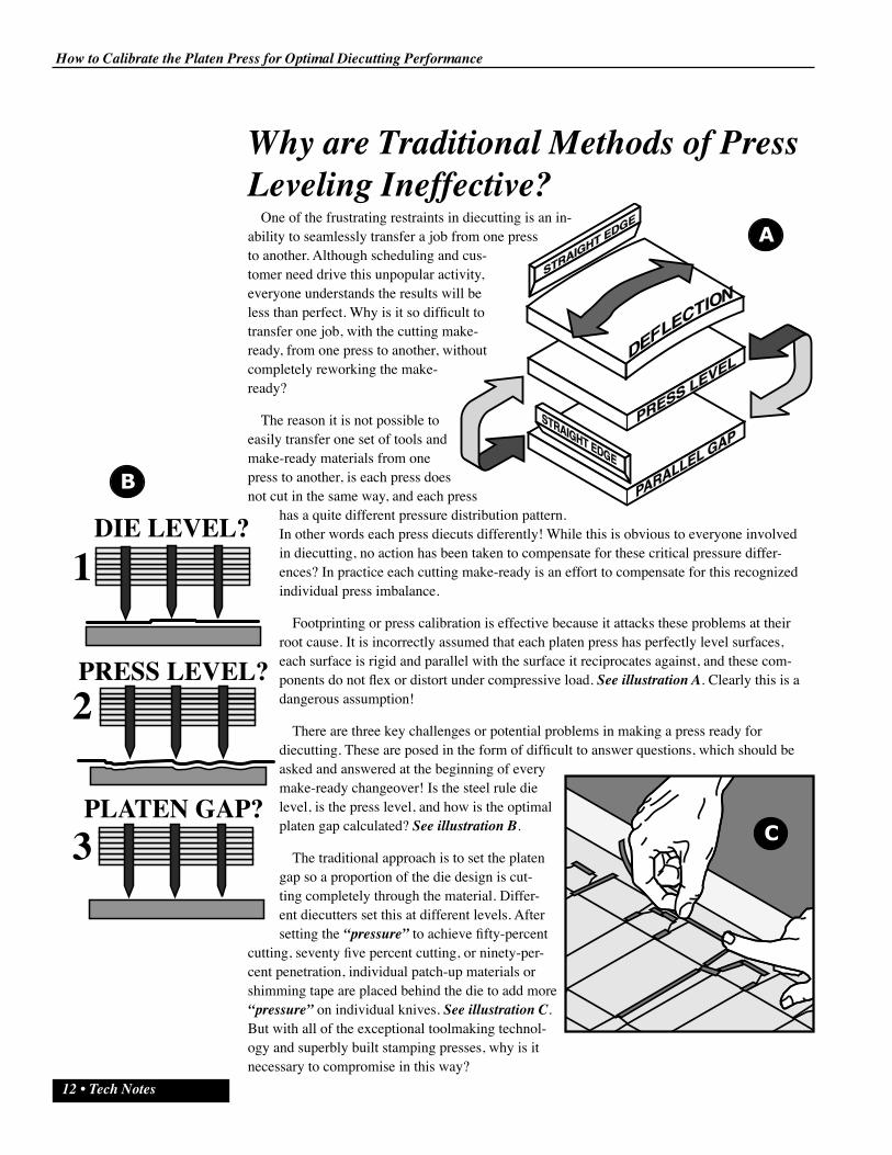
One of the frustrating restraints in diecutting is an in-ability to seamlessly transfer a job from one press to another. Although scheduling and cus-tomer need drive this unpopular activity, everyone understands the results will be less than perfect. Why is it so difficult to transfer one job, with the cutting make-ready, from one press to another, without completely reworking the make-ready?
The reason it is not possible to easily transfer one set of tools and make-ready materials from one press to another, is each press does not cut in the same way, and each press
has a quite different pressure distribution pattern. In other words each press diecuts differently! While this is obvious to everyone involved in diecutting, no action has been taken to compensate for these critical pressure differ-ences? In practice each cutting make-ready is an effort to compensate for this recognized individual press imbalance.
Footprinting or press calibration is effective because it attacks these problems at their root cause. It is incorrectly assumed that each platen press has perfectly level surfaces, each surface is rigid and parallel with the surface it reciprocates against, and these com-ponents do not flex or distort under compressive load. See illustration A. Clearly this is a dangerous assumption!
There are three key challenges or potential problems in making a press ready for diecutting. These are posed in the form of difficult to answer questions, which should be asked and answered at the beginning of every make-ready changeover! Is the steel rule die level, is the press level, and how is the optimal platen gap calculated? See illustration B.
The traditional approach is to set the platen gap so a proportion of the die design is cut-ting completely through the material. Differ-ent diecutters set this at different levels. After setting the “pressure” to achieve fifty-percent
cutting, seventy five percent cutting, or ninety-per-cent penetration, individual patch-up materials or shimming tape are placed behind the die to add more “pressure” on individual knives. See illustration C. But with all of the exceptional toolmaking technol-ogy and superbly built stamping presses, why is it necessary to compromise in this way?
B
DIE LEVEL?
PRESS LEVEL?
PLATEN GAP?
1
2
3

How to Calibrate the Platen Press for Optimal Diecutting Performance
Tech Notes • 13
The first challenge is the difficulty of machining any surface to be perfectly flat and level. See illustration D. It is clearly impossible to ma-chine large metal surfaces to a “Zero Tolerance.” Therefore a degree of
variation in the “flatness” of every surface is inevitable. Given that there are multiple machined surfaces in the standard platen stack, see illus-tration E, and four (4) of these are designed as “sacrificial and replace-able” tools, the cumulative degree of variation is multiplied many times. How flat and level is the steel rule die? Is every knife-edge set so the
edge of the blade conforms to the exacting tolerances inherent in these exceptional materials? See illustration F. The critical height tolerance of steel rule knife is plus 0.0005”- minus 0.000.”
Is the steel rule die, the cutting plate, the chase backplate, the patch-up cover sheet, and the press accurate to this degree of precision? The evidence demonstrates key problems in platen diecutting. These would include extensive time consumed in struggling to get a balanced and stable cutting impression, excess material waste and product variation, dust and loose fiber, domed and damaged cutting plates, and steel rule knives whose edges are
compressed and swaged. See illustration G. Clearly there are serious problems with current make-ready methods!
The goal in platen diecutting is to set the press so there is a zero gap between the tip of every blade edge and the cutting surface of the press. See illustration H. One of the reasons this is important is as we learnt earlier, the paperboard splits before the cutting blade touches the surface of the cutting plate. The second reason this factor is so critical is the ability to use this information to avoid the tip of the blade striking the cutting plate with such force, the cut-
ting edge of the knife is compressed, swaged, and damaged. This type of knife swaging will inevitably lead to more patch-up, which would result in more damage, and the destructive cycle continues!
The traditional solution has been to attack this variation using individual patch-up tape to compensate for a lack of flatness in the press, in the press components, and in the steel rule die! The disadvantage of using shimming tape to adjust an individual knife, is both the knife behind which the tape is po-sitioned is lifted higher, and a large area of the die is deformed and distorted. See illustration I.
STRAIGHT EDGE
ZEROGAP
Size of applied patch-up tape
Area of die impactedby shimming!
Is the Steel Rule die “within” Tolerance?
STRAIGHT EDGE
STRAIGHT EDGE

How to Calibrate the Platen Press for Optimal Diecutting Performance
14 • Tech Notes
This area of steel rule die distortion is called the Pressure Zone in diecutting and simply means when tape is applied to the back of the die, (to the patch-up sheet attached to top of the backplate of the chase), see illustration J, areas of the steel rule die far larger than the applied tape are distorted.
In practice, this means the shimming tape “theoretical-ly” applied to increase the pressure on a single knife to get it to cut, will impact many other blades in the vicinity of the individual knife being adjusted. These knives, which were cutting perfectly, are now over-pressurized, and upon the next im-pression they strike the cutting plate with excess force, they are prema-turely damaged, and patching has to continue! This leads to repeated and unpredictable patching/shimming until the make-ready is spongy, soft, and unstable.
In platen diecutting there are two alternative locations to apply patch-up tape. The traditional approach is to position shimming material behind the die, the far more effective approach is to apply shimming tape under the cutting plate! Shimming under the cutting plate rather than behind the dieboard can minimize the area of damage, because the Pressure Zone is far smaller. See illustration K. This means shimming is more accurate, it causes less damage to other knives, it takes far less time, and it will give a far more stable cutting impression for the length of the production run! An important advantage!
In practice, the closer the shimming material is to the cutting edge of the knife the smaller the pressure zone, the more accurate the adjustment, and the lower the amount of damage to the cutting edges in the dieboard. See illus-tration L.
Therefore, given these inher-ent weaknesses, the only place to position materials to compensate for the press footprint, or devia-tion from perfect flatness is under the cutting plate.
How do we map and measure the variation in the press pressure footprint, and how do we perma-nently compensate for the varia-tion the press mapping procedure will uncover?
K
ZONEOFINFLUENCE
ZONEOFINFLUENCE
The Impact of PatchingBehind the Die!
The Impact of PatchingUnder the Plate!
Patch-Up Sheet
Patch-Up Cover Sheet
Chase BackPlateSteel RuleDie
PressCuttingPlateLowerSlidingPlatenRecinolBed
Patch-Up AlternativesBehind the
Steel Rule DieUnder the
Cutting PlateChase BackPlate
Steel RuleDie
PressCuttingPlate
Patch-Up SheetLowerSlidingPlatenRecinolBed

How to Calibrate the Platen Press for Optimal Diecutting Performance
Tech Notes • 15
The Press Calibration Solution
In defining current methods of press leveling as being inconsistent there must be a practical, simpler, and a more effective alternative? This discipline is called Press Footprinting. The goal of footprinting is to calibrate the cutting press by measuring and compensating for the specific pressure distribution pattern of the press with the objective of creating a perfectly flat anvil for the steel rule die to cut against. The bottom line is Press Footprinting is one of the building blocks of an effective, and a productive press operation.
The disadvantages of this procedure are few: the time taken each quarter to evaluate, and possibly to recalibrate the press, and the care which must be taken to prevent damage to the foil footprint underlay. By comparison, the advantages are so overwhelming they are impos-sible to ignore. Footprinting the press results in 10 primary benefits.
& A fast, stable and simple to achieve kiss cut impression
& The effective life of the steel rule die is quadrupled
& Press and component damage are eliminated
& Material waste and press down time are minimized
& On press make-ready time is reduced considerably
& Press speed is optimized and nick sizes are reduced
& Crease formation and converting performance are improved
& Dust, Loose Fiber, and Flaking are virtually eliminated
& Stripping and blanking problems are greatly reduced
& Product quality and repeatability are enhanced
Combined with these advantages are the benefits of a simpler and a faster process. But it is the elimination of the “black-art” of make-ready, which results in press leveling predictabil-ity, and the knowledge and skill required to generate consistent results is considerably reduced. Without doubt, the ability to accurately predict and schedule changeover time, and to precisely define press speed and yield, make production scheduling and on-time delivery far less challenging. Even more critical is the impact on turnaround time, on throughput, on competitive excellence, and in the significant reduction in the cost of manufacturing.
This is a proven method of simplifying make-ready and improving every aspect of diecutting press performance. To begin it is necessary to create the measurement tool, which will be used to “map” the platen gap.
Press Footprinting ProceduresDiecutting
Make-Ready
01001 01
01 02/01
KBCClean the upper & lowersurfaces of the platenwell/tool cavity
Clean the upper & lowersurfaces of the lower slidingplaten bed
01
02
Clean the upper & lowersurfaces of the cutting plate
03
Clean & smooth the inside& upper surface of the diechase backplate
04
Clean & smooth the lower &upper surface of the patch-up cover sheet
05
Clamp/bolt the mapping testdie to a calibrated table
06
Plane all of the rule in thedie perfectly flat and level
07
Install the mapping die inthe press chase
08
Verify there are no chasebolts protruding above thesurface of the chase
09
Attach normal patch-upsheet material to the chasebackplate backplate
10
Assemble all of thefootprinting materials on-press
11
Assemble all of thefootprinting tools on-press
12
Back the press pressuresetting completely off
13
Install the chase & mappingdie into the press
14
Withdraw the cuttingplate/sliding bed from thepress
15

How to Calibrate the Platen Press for Optimal Diecutting Performance
16 • Tech Notes
Designing & Fabricating the Calibrated Press Mapping Die
The most effective method of measuring the platen gap across the entire press is to use the same tool which is used in daily production, the steel rule die. However, this die must be made with some special characteristics if it is to provide an accurate map of pressure variance across the
entire cutting surface.
The first key criteria is that the die must be made with creasing rule and not cutting rule!
This is because the rule in the die is only going to be used as a measuring device and is not designed to
cut or to penetrate a material, and the standard cutting edges of a blade are too easily damaged, which would undermine repeated use of this valuable tool. However, designing and fabricating the dieboard is only the
initial step in creating an effective press measuring tool.
The dieboard should be machined with the “Pulse Lasercut” method to ensure a serrated kerf profile, which
will support a “floating-blade.” See illustration A. This is far more effective than the alternative, which is
the standard “Continuous Wave” lasercutting method. See illustration B.
This technique often generates excessive kerf variation, which is unacceptable for this critical mapping die application. The goal is to
ensure the creasing rule “self-levels” to give a precise measurement of the platen gap. There-fore, it is also vital to set the kerf width to the actual creasing rule thickness, which will be inserted into the dieboard, and the kerf should be a loose fit to compensate for inevitable stacking as the die is ruled. See illustration C & D. A “loose” fit means the last rule inserted into the dieboard can be pushed into the lasercut kerf with minimal effort and pressure!
The mapping die design is a 2” squared grid, (this size should be varied based upon press size), and the most effective bridging pattern is to have a single 0.375” bridge in each side of each aligned square. The bridges in the design pattern will naturally align from one side of the die to the next. See illustration E.
It is important to remember, the size of the bridge programmed is NOT the size of the bridge lasercut, and this reduction in size and strength must be factored into tool design and fabrication. See illustration F.
It is also important to depress each bridge, particularly when using a 0.75” thick dieboard. See illustration G. This will ensure there is minimal distortion in the critical upper edge of each creas-ing blade.
KERF/RULE INTEGRATION?(Rule Thickness Versus Kerf Width?)
1/4 InchProgrammed
Bridge Width
7/32 Inch
Laser Kerf
Bridge
"Wood"
Width
Critical Bridge Alignment
How to Calibrate the Platen Press for Optimal Diecutting Performance
Tech Notes • 17
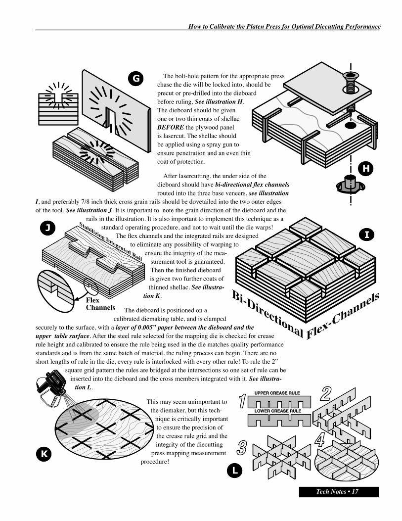
The bolt-hole pattern for the appropriate press chase the die will be locked into, should be precut or pre-drilled into the dieboard before ruling. See illustration H. The dieboard should be given one or two thin coats of shellac BEFORE the plywood panel is lasercut. The shellac should be applied using a spray gun to ensure penetration and an even thin coat of protection.
After lasercutting, the under side of the dieboard should have bi-directional flex channels routed into the three base veneers, see illustration
I, and preferably 7/8 inch thick cross grain rails should be dovetailed into the two outer edges of the tool. See illustration J. It is important to note the grain direction of the dieboard and the
rails in the illustration. It is also important to implement this technique as a standard operating procedure, and not to wait until the die warps!
The flex channels and the integrated rails are designed to eliminate any possibility of warping to
ensure the integrity of the mea-surement tool is guaranteed. Then the finished dieboard is given two further coats of thinned shellac. See illustra-
tion K.
The dieboard is positioned on a calibrated diemaking table, and is clamped
securely to the surface, with a layer of 0.005” paper between the dieboard and the upper table surface. After the steel rule selected for the mapping die is checked for crease rule height and calibrated to ensure the rule being used in the die matches quality performance standards and is from the same batch of material, the ruling process can begin. There are no short lengths of rule in the die, every rule is interlocked with every other rule! To rule the 2”
square grid pattern the rules are bridged at the intersections so one set of rule can be inserted into the dieboard and the cross members integrated with it. See illustra-
tion L.
This may seem unimportant to the diemaker, but this tech-
nique is critically important to ensure the precision of the crease rule grid and the integrity of the diecutting
press mapping measurement procedure!
Stabilizing Integrated Rail
FlexChannels
Flex-ChannelsBi-Directional

How to Calibrate the Platen Press for Optimal Diecutting Performance
18 • Tech Notes
To further enhance the seating of the rule, and to improve the ease and safety of insertion, the top of every kerf is opened slightly with a marlin spike. See illustration M. This “Kerf-Open Technique” will simplify and speed up insertion of long lengths of the creasing rule with no damage to the walls of the kerf.
Before each rule is inserted the base of the blade should be given a thin coat of oil, using the oil ruling technique. See illustration N. This is important as it will ease the safe insertion of each blade, it will ensure effective rule seating, it will improve blade “Self Leveling”, it will seal all the exposed end grain in each kerf wall, it will eliminate any potential for loose rule, and it will extend the useful life of the mapping tool. It is also useful to select a creasing rule with a double edge, in other words both the top and the bottom edge of the rule are rounded. This will ease insertion and
improve blade seating.
Every creasing rule is inserted carefully, and to prevent rule distortion a length of wood or plastic is used as a hammer guide. See illustration O.
The finished dieboard should be planed flat using the
Bar Plate Planing tool and a Deadblow ham-mer. See illustration P.
The complete die should be unclamped from the table, inverted, and the rear of the tool
cleaned with a rotary wire brush in a drill or a router. See illustration Q.
It is important to check the rear of the die both to ensure it is perfectly clean, but also to look for specific rule which is poorly seated. The paper can then be removed from the table, the table surface is cleaned and the die is re-clamped to the surface. The mapping die should be re-planed a second time, without the paper membrane, to make absolutely sure every creasing rule is seated perfectly, and level with every other rule in the die.
The goal is to make absolutely sure that the mapping procedure and the use of the mapping die as a key measurement tool on-
press, see illustration R, is not compro-mised by poor preparation. It must be perfectly level, each rule must be able to float independently, and it must be part of the solution and not part of the problem.
BEFORE AFTER

How to Calibrate the Platen Press for Optimal Diecutting Performance
Tech Notes • 19
The dieboard should be rubbered with a very dense ejection material, such as Green Gorilla or T-75. The rubber should fill every cavity with 1.75” squares of material. See illustration S. It is important this rubber is cut precisely to a consistent size and is not too tight a fit in each cavity. The most effective approach is to cut the rubber squares using standard bench band saw, or a waterjet cutting system. When the rubber is glued into each cavity it is important the rubber is not pressed hard up against the creasing rule in the die. See illustration T.
In this application the rubber is not included to play the role of an ejector, but to give compressive resistance to the mapping die, to ensure the press is measured under high pressure and face the type of loads it would face in normal production
diecutting. It is vital to remember the rule and the rub-ber are the key players in the measurement and the
mapping process. While the dieboard is important, it is simply fulfilling the role of a tool holder and a tool
platform.
The very dense rubber ensures the press will be measured under consider-able pressure, as a static non stress measurement would not reproduce a normal produc-
tion environment. Secondly, the creasing rule in the die is the measur-
ing tool so each blade should be able to level and seat under pressure and not give
a false reading. The key criteria for this die is the “Z-Axis” measurement of every rule seated in the finished mapping tool. See illustration U. This is our measuring device for determining both the degree of press variation, and the suc-cess of the footprinting metal underlay, inserted to compensate for the imbalance.
To protect the investment in this mapping tool it should be clamped flat when it is not in use or stored in a suspended condition in a balanced environment. See illustration V. The mapping tool represents an investment in a system of measurement, which has an unlimited
life, if it is stored and protected properly.
Note illustration W shows a three pin suspended storage method and not the standard and unsafe two pin approach! Although this is a heavy tool, and that alone would justify using a three pin system, using three suspension pins is the most effective method for all tools. This makes accessing and inspect-ing tools easier, safer, and more efficient.
1
OFF
IN/M
M
0.09370
1
EjectionSquares
Mapping Die Ejection Pattern

How to Calibrate the Platen Press for Optimal Diecutting Performance
20 • Tech Notes
Effective manufacturing is in the details, and it is easy to over-look seemingly inconsequential factors, which can seriously undermine both the mapping procedure and daily produc-tion diecutting. To ensure the footprinting procedure is effective it is important to prepare carefully and to consis-tently apply a Standard Operating Procedure. See illustration A. The first step is to prepare the diecutting press
On-press preparation requires installing the die/chase, cleaning the platen well, clean-ing all the press components in the platen stack, assembling tools and materials, and
bringing the press up to operational temperature.
The first step is to completely back off any pressure setting retained from the previous job. With some experience it will be possible to pre-set the initial mapping die
pressure to save on-press time. This is why it is important to videotape the entire procedure, see illustration B, and to make sure the observer take copious notes. See illustration C.
Although it is more effective to install the mapping die in the chase in the diemaking area, or in the pre-press area on a diemakers table, the die is often locked into the chase
on-press. It is important when locking the die into the chase to follow some simple practices. The backplate of the chase should be thoroughly cleaned of old tape, adhesive, and accumulated dirt. In addition, the inside surface of the backplate should be cleaned and leveled using a diamond stone, see illustration D, paying particular attention to burrs and to each of the boltholes in the backplate.
The dieboard is positioned in the chase and lightly ten-sioned, using the chase lock-up mechanism. It is vital to understand there is absolutely no need for this die or any other die to be locked into a chase with anything more than the lightest pressure. Excess lock-up pressure will distort the mapping die and the chase and undermine the
measurement process. Therefore, the mapping die is bolted first with as many bolts as possible, and light pressure applied sparingly to slightly tension the dieboard in position. It is vital none of the bolt heads pro-trude above the surface of the backplate, see illustration E, as this will also distort the impressional pattern. With the lock-up finished the mapping die and the chase should be perfectly flat and level. See illustration F.
The platen stack should be cleaned. This means the lower and upper platen well surface, the underside and top of the lower sliding bed, both sides of the cutting plate, and both sides of the patch-up cover sheet. See illustration G. (In a professional operation these important tasks would be completed on a weekly basis.)
On-Press Preparation
How to Calibrate the Platen Press for Optimal Diecutting Performance
Tech Notes • 21
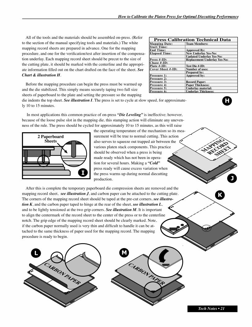
All of the tools and the materials should be assembled on-press. (Refer to the section of the manual specifying tools and materials.) The white mapping record sheets are prepared in advance. One for the mapping procedure, and one for the verification/test after insertion of the compensa-tion underlay. Each mapping record sheet should be precut to the size of the cutting plate, it should be marked with the centerline and the appropri-ate information filled out on the chart drafted on the face of the sheet. See Chart & illustration H.
Before the mapping procedure can begin the press must be warmed up and the die stabilized. This simply means securely taping two full size sheets of paperboard to the plate and setting the pressure so the mapping die indents the top sheet. See illustration I. The press is set to cycle at slow speed, for approximate-ly 10 to 15 minutes.
In most applications this common practice of on-press “Die Leveling” is ineffective; however, because of the loose pulse slot in the mapping die, this stamping action will eliminate any uneven-ness of the rule. The press should be cycled for approximately 10 to 15 minutes, as this will raise
the operating temperature of the mechanism so its mea-surement will be true to normal cutting. This action also serves to squeeze out trapped air between the various platen stack components. This practice should be observed when a press is being made ready which has not been in opera-tion for several hours. Making a “Cold” press ready will cause excess variation when the press warms up during normal diecutting production.
After this is complete the temporary paperboard die compression sheets are removed and the mapping record sheet, see illustration J, and carbon paper can be attached to the cutting plate. The corners of the mapping record sheet should be taped at the pre-cut corners, see illustra-tion K, and the carbon paper taped to hinge at the rear of the sheet, see illustration L, and to be lightly tensioned at the two grip corners. See illustration M. It is important to align the centermark of the record sheet to the center of the press or to the centerline notch. The grip edge of the mapping record sheet should be clearly marked. Note, if the carbon paper normally used is very thin and difficult to handle it can be at-tached to the same thickness of paper used for the mapping record. The mapping procedure is ready to begin.
Mapping Date:Start Time:End Time:Elapsed Time:
Press #-ID:Chase #-ID:Plate #-ID:Cover Sheet #-ID:
Pressure 1:Pressure 2:Pressure 3:Pressure 4:Pressure 5:Pressure 6:
Press Calibration Technical DataTeam Members:
Approved By:New Underlay Yes-No:Updated Underlay Yes-No:Replacement Underlay Yes-No:
Test Die #-ID:Number of uses:Prepared by:Approved by:
Record Paper:Paper Thickness:Underlay material:Underlay Thickness:
2 PaperboardSheets
MAPPING
RECORD
SHEET
CARBON PAPER
CARBON PAPER

How to Calibrate the Platen Press for Optimal Diecutting Performance
22 • Tech Notes
With the press at operating temperature and the mapping materials attached to the cutting plate, the mapping procedure can begin. Footprinting a press for the first time requires
patience as it is somewhat time consuming. It is a new procedure and time should be taken so everyone involved understands and agrees with each step. It is impor-tant to remember the earlier recommendation to videotape the entire sequence so
it can be reviewed carefully, as part of an assessment discipline, and as a training tool for team members who were not able to participate.
As there is no previous information for pressure setting for each step, pressure is added gradu-ally and carefully. As each impression is taken the carbon paper is hinged back and the mapping record
sheet examined for any carbon marks from the rule grid in the die. Usually the ejection pattern will show first; however, eventually an image of the mapping die grid pattern will appear in some areas of the paper.
The initial grid image showing is obviously the highest area of the platen pressure pattern, or the areas of the cutting plate which would normally strike the steel rule die first. To desig-
nate each area as it appears, different colored felt markers will be used; however, the first marking of each area should be done in pencil. Footprinting is a subjective process in which the diecutter and the diecutting team must make decisions about the shape and size of each pressure area. This decision-making process is not dif-ficult; however, it is usually a consensus decision. Therefore, by starting in pencil,
each person involved can discuss the shape until a final decision is made.
At a point of consensus the first area or the highest area of the platen should be outlined in black. See illustration A. At the same time the mapping data record should have the first pressure setting noted, for future footprinting on this press. See Chart on previous page.
The carbon is re-taped down and pressure increased until the next area emerges. See illustration B. This second level should be outlined with a red felt marker. The carbon is re-taped down and pressure
increased until the next area emerges. This procedure should be com-pleted with each layer outlined with a different colored marker,
until the complete grid pattern is visible, even faintly in the last area. See illustration C.
Making sure all of the data from the press settings and other relevant information is complete. The first step
of footprinting, creating a map of the high and low spots of the press under pressure, is complete. This will be kept as a record should the resulting underlay become lost or damaged and as a reference
point for both settings and changes in the footprint over the next quarter. The mapping record sheet will now be used to cre-
ate the underlay, which is to be used to compensate for the pressure imbalance.
It is interesting to note that if it were possible for a press to be perfectly level and parallel a perfect kiss cut im-
age of the grid pattern would have been evenly marked across the mapping record sheet. As this is impossible, it is time to create
the compensation underlay.
The Mapping ProcedureAREA 01
AREA 01
AREA 02
AREA 03
AREA 04
AREA 02

How to Calibrate the Platen Press for Optimal Diecutting Performance
Tech Notes • 23
The marked up mapping record sheet is now removed from the press and taped down to a layout table or a large flat surface. (It is important to use the mapping record sheet to create the foil underlay, howev-er, this sheet should be kept and stored for future reference.) Over the top of the map is positioned a thin Mylar sheet, which will be the carrier and the protector for the foil shingled underlay material. The Mylar should have the centerline notch po-sition, the plate fastening holes, and the lateral plate adjusters cut free to simplify precise installation. This is made the same size and shape as the cutting plate/mapping record sheet and is
taped down so it is hinged at one side of the sheet for easy access when gluing the underlay to the underside of this material. See illus-
tration A.
Several pieces of Mylar are then used to trace the shape of the low-pressure areas from
the mapping sheet. These are then used to transfer this profile to a 0.002”
thick foil sheet, by positioning the Mylar over the foil and by tracing each underlay shape with a
pointer tool so the pressure indents the foil. See illustration B. Scribe indentation reference measurement points and orienta-
tion arrows to avoid registration confusion.
These pieces of foil are then cut slightly smaller than each shape using scissors, and are positioned on the mapping sheet. Very small amounts of Superglue are added, strategically placed across the surface of each foil piece, and then the Mylar cover sheet is pressed down onto the foil. See illustration C. This action tack-glues the foil underlay materials to the underside of the Mylar carrier sheet.
As a simple guideline to creating the foil underlay shape the following assem-bly checklist should be used. The carbon imprint of the mapping die grid that appeared first as pressure was increased needs no compensation foil, as this is obviously the highest area of the cutting anvil. The area that appeared second requires one layer, the area that appeared third requires two layers, and the area that appeared fourth requires 3 layers, and so on. This simple step-by-step checklist helps to clarify what may at first appear to be a difficult task. However, take your time and think it through. Make sure the entire team understands what is happening and why each step is executed. Discuss and brainstorm each step where necessary. As this is both a new and a critically important diecutting discipline, it is important everyone is confident about every step in the entire procedure.
Creating the Footprint Underlay
Mapping Record Sheet
Underlay Mylar
Cover Masking Tape “Hinge”
FOIL
MYLAR PATTERN
AREA 1No Material
AREA 21 Foil Layer
AREA 32 Foil Layers
AREA 43 Foil Layers

How to Calibrate the Platen Press for Optimal Diecutting Performance
24 • Tech Notes
Remember this is the first time for a new procedure so it may not progress seam-lessly, or work perfectly the first time, however, it can and should be repeated as every
time the discipline is executed skill, knowledge and experience grows.
When this procedure is complete the new Mylar Foil Underlay is ready to be inserted into the press. See illustration D. To make sure it does not slide on the Recinol Bed, as the cutting plate is removed and inserted, it is a good idea to apply a small amount of contact adhesive to four points, one in
each quadrant, on the underside of the under-lay. Now we are ready to see how accurately
we have measured the pressure distribution variation of the press, and how effectively
the press footprint compensates for that variation.
The footprint underlay is positioned under the cutting plate on the press, the pressure is backed off, and the mapping
procedure previously described is repeated. However, the tonnage set-tings, which were recorded during the mapping procedure, are not accurate as the addition of the underlay and the Mylar Sheet has changed the platen gap of the press. Pressure is increased until the test die grid appears on the mapping sheet.
However, this time the impression should be even and perfectly consistent from one
side of the press to the next. See illustration E.
Do not be concerned if there are still low spots, this is after all the first time you have executed the footprinting procedure. If they are minor blemishes
in the carbon image, ignore them for the moment and assess subse-quent diecutting production performance. However, if the low
spots are clearly defined then it is important to add more material to the underlay to compensate. As we did in the first
procedure mark those low spots on the mapping record sheet, see illustration F, then cut
pieces of foil to match these shapes. Attach the
additional compensa-tion pieces to the underside of the footprint underlay using Superglue. See illustration G.
As this procedure is executed on each press and repeated each quarter the entire team will gain competence and confidence in press footprinting.
Underlay is accurately registeredunder the cutting plate.

How to Calibrate the Platen Press for Optimal Diecutting Performance
Tech Notes • 25
To overcome the inherent variability of the stamping mechanism in platen diecutting, it is vital to implement some form of footprinting. However, the design of many diecutting impressional systems do not provide the most effective location for positioning the footprint underlay. In platen diecutting, the principle of shimming or patch-up, to close the gap, requires material to be added somewhere in the platen stack, aligned with the knife or areas of the die-layout which are not cutting. And although the common
shimming location is behind the cutting die, see illustration A, it is important to recognize this is neither the only location, nor the most effective shimming point. It is also important to reiterate an im-portant question. What are we compensating for? Is it the press, is it the die, or is it the setting of the distance between the upper steel rule die and the lower anvil?
In practical terms patch-up is attempting to compensate for a gap between the tip of the knife and the anvil, damage to the tip of the cutting knife requiring more penetration force, and a low spot in the cutting anvil. See illustration B. The primary role of the professional diemaker and diecutter is to recognize the diecutting cutting make-ready problem, to understand the cause, and to change methods and practices, to find more a effective solution.
Patch-up is an ineffective band aid, and while it provides a crudely effective short term solution, it does not attack the source nor eliminate the basic problem. Which means every make-ready is a struggle to overcome the same technical problems which have plagued the process for far too many years. Although it is commonly referred to as “patch-up”, this adjustment to the platen gap is a shimming process. This simply means a spacer is inserted between the layers of components to “deform” tools to compensate for a gap between the tip of the knife and the surface of the anvil. See illustration C.
To make this as accurate as possible it is important to position the material where it will have the smallest inpact on surround-ing tool components, and as close to the knife as possible. Plac-ing patch-up materials in the steel rule die layer of components distorts the tooling, particularly when positioned behind the cutting die. See illustration D. This approach is far less accurate than placing materials as close to the knife cutting edge as possible. The greatest pressure adjustment precision is achieved when positioning patch-up material under the cut-ting plate. See illustration E.
Footprint Location Alternatives
C
E
D
Three key patch-up sources
Gap - Damage - Low Spot
Individual Patch-Up is Tool Shimming/Deflection
Individual Patch-Up is Travel Distance Adjustment
ZONE OFINFLUENCE
Patch-Up Tape
EXTENSIVEDAMAGE
MINIMALDAMAGE

How to Calibrate the Platen Press for Optimal Diecutting Performance
26 • Tech Notes
Many experienced diecutting professionals combine the two approaches, where a design has key features or critical “internal” knives.
For example the external knives in a design could be patched behind the die as normal, however, the sensitive internal knives, are patched under the cutting plate. See il-lustration F. This is often referred to as Double Patch-Up or Precision Patch-Up, and it is very effective!
However, selecting the most effective position for the underlay is not always possible because of the design of the press or the logistics of how the press is used. Therefore, in practical terms there are four location alternatives for the footprint. Two are under the cutting plate and two are behind the steel rule die.
The most effective location is to mount the underlay directly to the upper surface of the lower sliding platen, see illustration G in the chart to the left. This requires a degree of care when removing and replacing the cutting plate. To minimize this type of potential problem, it is also effective to attach the underlay to the underside of the cutting plate. See illustration H in the chart to the left.
Alternatively, and not as effective, the underlay can be attached to the upper surface of the die chase, or attached to the underside of the patch-up sheet. See illustration I in the chart to the left.
When the underlay has to be attached directly to the back of a die which has no protective backplate the Mylar cover should be positioned on the underside of the underlay, resting against the rear die surface. See il-lustration J. Finally, the underlay can be attached to the
underside of the patch-up cover sheet. See illustration K in the chart above. Although position-ing the footprint underlay under the cutting plate is most effective, using an underlay behind the die has enormous advantages, rather than not making the compensation effort.
Press Footprinting is a foundation disci-pline and a key principle of effective platen diecutting. The most important action is to implement this discipline, no matter what underlay registration options are available.
External KnivesPatched Behind
the Die
InternalKnives
Patched Underthe Cutting
Plate
FOIL
UNDERLAY
Mylar Cover Sheet
“Against” the back of the steel
rule die.
Patch-UpSheet
Patch-UpSheet
Patch-UpCover Sheet

How to Calibrate the Platen Press for Optimal Diecutting Performance
Tech Notes • 27
Footprinting is an important and an essential ingredient of effective platen diecutting; however, there is a transition period between the old procedures and the new methods, which must be managed carefully. When a die design is patched up in the traditional manner, on a press which has not been calibrated, the die is damaged based upon the inconsistent pressure distribution pattern of a non-calibrated press. (The goal of press footprinting is of course to eliminate this degree of steel rule, knife-edge damage.)
Therefore, if a new or reruled die is made ready on a calibrated press the procedures are identical to any standard make-ready. However, if an old die, previously used with an existing patch-up sheet, must be run on the calibrated press, the footprint is temporarily removed, and the make-ready proceeds as normal. At the conclusion of the production run the footprint is replaced if a new or a reruled die is to be used for the next production job.
It is vital to remember existing dies have been damaged by an uneven, non-calibrated press, and using the old patch-up sheet, or even making a new patch-up sheet, would create more damage to the die and generate poor results. The footprint or the new underlay is designed to level the press, but all of the old jobs have been made-ready on non-level presses, and the steel rule dies have been damaged and the make-ready adjusted to compensate for the imbalance!
One of the great advantages of footprinting is jobs can be easily transferred from calibrated press to calibrated press with their respective patch-up sheets with minimal disruption. However, if a job run on a calibrated press is transferred to a non calibrated press the die will get dam-aged and the make-ready or existing patch-up sheet will almost certainly need to be replaced and reworked. Eventually, as steel rule dies are reruled or are new, the footprint will become a permanent part of the platen stack.
It is usually a good idea to make two identical footprint underlays just in case the one in use is damaged. Although the original mapping record sheet is kept as a reference it is much simpler and less time consuming to replace the damaged underlay with the back up.
There are a few additional precautions, which are important. As each make-ready is complete on a calibrated press the tonnage settings should be recorded to enable an accurate pressure picture of the press to be statistically defined. This will simplify future make-ready procedures and eliminate problems with excess pressure. The footprint should be examined to determine it is still in good condition every two weeks, and the press should be re-calibrated every three months.
In addition, it is important to calibrate each steel rule die used in platen diecutting, irrespec-tive if the press is footprinted or not, as half the pressure adjustment problems are the result of steel rule dies which are not level and flat. Making sure the mapping die is stored correctly will protect the valuable investment in the test die.
Finally, it is important to remember the insertion of footprint materials under the cutting plate will change the platen gap and make old pressure settings obsolete. In other words, when inserting a die you are familiar with, you will have to set the initial pressure slightly lower to compensate for the additional thickness of shim material under the cutting plate.
Footprint Management: New & Old Job Procedures
Preparation SOP
How to Calibrate the Platen Press for Optimal Diecutting Performance
28 • Tech Notes
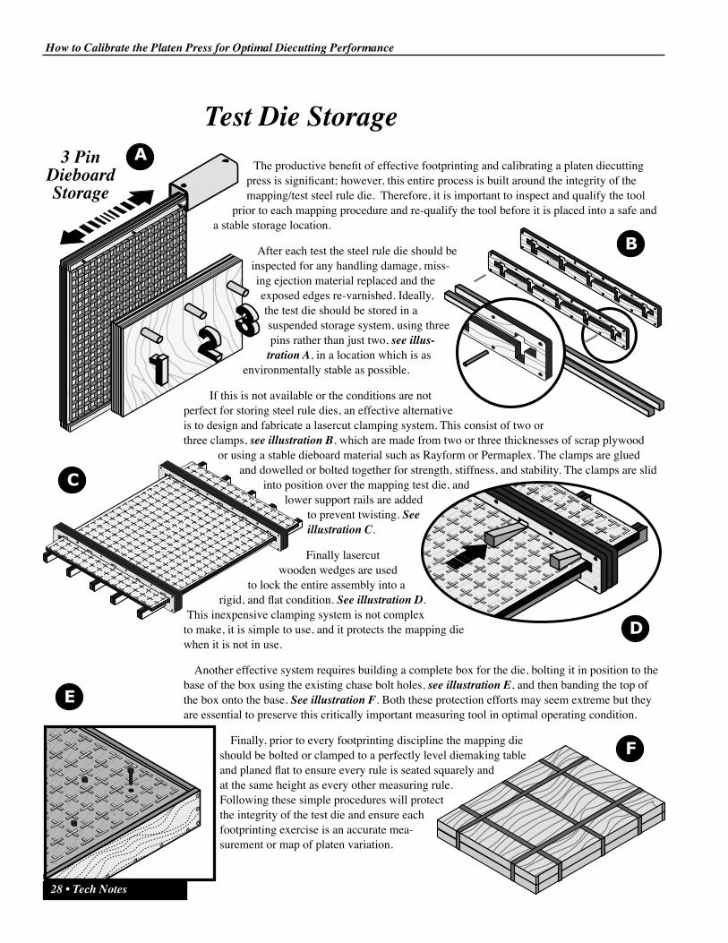
Test Die StorageThe productive benefit of effective footprinting and calibrating a platen diecutting
press is significant; however, this entire process is built around the integrity of the mapping/test steel rule die. Therefore, it is important to inspect and qualify the tool
prior to each mapping procedure and re-qualify the tool before it is placed into a safe and a stable storage location.
After each test the steel rule die should be inspected for any handling damage, miss-ing ejection material replaced and the exposed edges re-varnished. Ideally, the test die should be stored in a suspended storage system, using three pins rather than just two, see illus-
tration A, in a location which is as environmentally stable as possible.
If this is not available or the conditions are not perfect for storing steel rule dies, an effective alternative is to design and fabricate a lasercut clamping system. This consist of two or three clamps, see illustration B, which are made from two or three thicknesses of scrap plywood
or using a stable dieboard material such as Rayform or Permaplex. The clamps are glued and dowelled or bolted together for strength, stiffness, and stability. The clamps are slid
into position over the mapping test die, and lower support rails are added
to prevent twisting. See illustration C.
Finally lasercut wooden wedges are used
to lock the entire assembly into a rigid, and flat condition. See illustration D.
This inexpensive clamping system is not complex to make, it is simple to use, and it protects the mapping die when it is not in use.
Another effective system requires building a complete box for the die, bolting it in position to the base of the box using the existing chase bolt holes, see illustration E, and then banding the top of the box onto the base. See illustration F. Both these protection efforts may seem extreme but they are essential to preserve this critically important measuring tool in optimal operating condition.
Finally, prior to every footprinting discipline the mapping die should be bolted or clamped to a perfectly level diemaking table and planed flat to ensure every rule is seated squarely and at the same height as every other measuring rule. Following these simple procedures will protect the integrity of the test die and ensure each footprinting exercise is an accurate mea-surement or map of platen variation.
E
3 PinDieboardStorage
How to Calibrate the Platen Press for Optimal Diecutting Performance
Tech Notes • 29
Tools & MaterialsThe tools and materials required to footprint each press are relatively few; however, it will
simplify the process and allow the team to concentrate on the mapping procedure if everything is in place prior to the test. These tools, materials, and or components should be compiled into a pre-footprinting checklist
The materials required are as follows:
‚ Double Thickness of Carbon Paper (Bar-Plate)
‚ Aluminum 0.002” foil (Bar-Plate)
‚ White 0.005” Machined Finished Paper (Several sheets Pre-Cut to Size)
‚ Two full size Mylar Sheets
(Pre-Cut to Size)
‚ Masking Tape
‚ Colored Felt Markers
‚ Superglue & 3M77
‚ Rags & Cleaning Materials
‚ Paperboard Storage Tubes
The tools required are as follows:
‚ A Utility Knife & Spare Sharp Blades
‚ Razor Blade Knife
‚ Large Pair of Scissors
‚ Sharpening/Diamond Stone
‚ Large File
‚ Paper Micrometer/Vernier
‚ Tape Measuring Rule
‚ Straight Edge
‚ Rule Pullers
‚ Large Scraper
‚ Dead Blow Hammer (Bar-Plate)
‚ Diemakerʼs Planing Tool (Bar-Plate)
‚ Pencil & Sharpener
‚ Marking Tool/Scribe
With the tools and materials in place on-press the footprint procedure can be executed quickly and effectively.

How to Calibrate the Platen Press for Optimal Diecutting Performance
30 • Tech Notes
The steps or procedures required to implement the press calibration discipline are simple and straight-forward; however, they should be memorized to ensure the methods are applied consistently. Should you find an alternative sequence or an additional step, which is necessary because of press technology or the configuration of the platen, add it to the SOP so everyone practices the same technique.
Standard Operating Procedures
Step 01 Clean the upper & lower surfaces of the platen well/tool cavityStep 02 Clean the upper & lower surfaces of the lower sliding platen bedStep 03 Clean the upper & lower surfaces of the cutting plateStep 04 Clean & smooth the inside & upper surface of the die chase backplateStep 05 Clean & smooth the lower & upper surface of the patch-up cover sheetStep 06 Clamp/bolt the mapping test die to a calibrated tableStep 07 Plane all of the rule in the die perfectly flat and levelStep 08 Install the mapping die in the press chaseStep 09 Verify there are no chase bolts protruding above the surface of the
chase backplateStep 10 Attach normal patch-up sheet material to the chase backplateStep 11 Assemble all of the footprinting materials on-pressStep 12 Assemble all of the footprinting tools on-pressStep 13 Back the press pressure setting completely offStep 14 Install the chase & mapping die into the pressStep 15 Withdraw the cutting plate/sliding bed from the pressStep 16 Install two full size sheets of paperboard on the surface of the cutting plateStep 17 Set the pressure of the press to partially indent the upper of the two sheetsStep 18 Run the press for approximately 15 minutesStep 19 Remove the indentation sheets from the cutting plateStep 20 Back the press pressure setting completely offStep 21 Install a white mapping record sheet to the surface of the cutting plateStep 22 Install a sheet of carbon paper face down over the mapping record sheetStep 23 Gradually increase pressure/reduce the platen gapStep 24 Check frequently to determine the first impression of the mapping gridStep 25 Discuss the shape and pressure setting for the first impressionStep 26 Trace the outline of the first impression area(s) with a pencil Step 27 Discuss the pattern with the team and remark the pressure profile with a
black felt marker Step 28 Record the first Pressure setting on the mapping record sheet
How to Calibrate the Platen Press for Optimal Diecutting Performance
Tech Notes • 31
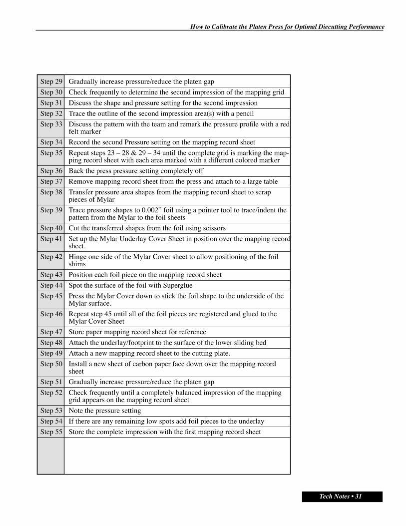
Step 29 Gradually increase pressure/reduce the platen gap Step 30 Check frequently to determine the second impression of the mapping gridStep 31 Discuss the shape and pressure setting for the second impression Step 32 Trace the outline of the second impression area(s) with a pencilStep 33 Discuss the pattern with the team and remark the pressure profile with a red
felt markerStep 34 Record the second Pressure setting on the mapping record sheetStep 35 Repeat steps 23 – 28 & 29 – 34 until the complete grid is marking the map-
ping record sheet with each area marked with a different colored markerStep 36 Back the press pressure setting completely off Step 37 Remove mapping record sheet from the press and attach to a large table Step 38 Transfer pressure area shapes from the mapping record sheet to scrap
pieces of Mylar Step 39 Trace pressure shapes to 0.002” foil using a pointer tool to trace/indent the
pattern from the Mylar to the foil sheetsStep 40 Cut the transferred shapes from the foil using scissors Step 41 Set up the Mylar Underlay Cover Sheet in position over the mapping record
sheet. Step 42 Hinge one side of the Mylar Cover sheet to allow positioning of the foil
shims Step 43 Position each foil piece on the mapping record sheet Step 44 Spot the surface of the foil with Superglue Step 45 Press the Mylar Cover down to stick the foil shape to the underside of the
Mylar surface. Step 46 Repeat step 45 until all of the foil pieces are registered and glued to the
Mylar Cover Sheet Step 47 Store paper mapping record sheet for reference Step 48 Attach the underlay/footprint to the surface of the lower sliding bed Step 49 Attach a new mapping record sheet to the cutting plate. Step 50 Install a new sheet of carbon paper face down over the mapping record
sheetStep 51 Gradually increase pressure/reduce the platen gapStep 52 Check frequently until a completely balanced impression of the mapping
grid appears on the mapping record sheetStep 53 Note the pressure settingStep 54 If there are any remaining low spots add foil pieces to the underlayStep 55 Store the complete impression with the first mapping record sheet

How to Calibrate the Platen Press for Optimal Diecutting Performance
32 • Tech Notes
Brainstorming, Notes & Ideas“Many ideas grow better when transplanted into another mind than in the one where they sprung up.” Oliver Wendell Holmes
How to Calibrate the Platen Press for Optimal Diecutting Performance
Tech Notes • 33
Summary
The tremendous success of this technique is ample evidence of its importance in platen diecutting; however, there are probably 10 reasons you should footprint each press. The real benefits include:
1. Higher quality, more consistent and repeatable diecut parts.
2. Simpler and faster press changeover.
3. Faster press speed and reduced down/lost press time.
4. Minimal patch-up, less cutting variation, and lower waste.
5. The elimination of dust, loose fiber and flaking.
6. Double the life of the die and the counter/matrix tools.
7. Better sheet-control with less and smaller nicks.
8. Lower the cost of manufacturing
9. Reduce the complexity and the stress of diecutting.
10. Enable jobs to be transferred from press to press seamlessly.
There are many other benefits to be gained using this practical and simple method of stabilizing the platen diecutting press. However, as a press operator I can attest to the reduction in stress and
the satisfaction of manufacturing quality con-verted products as a great source of satisfaction. If you have any problems, feel free to call me at 1.360.385.4214, or e-mail me at [email protected].
It is also useful to remember Eddie Rick-enbackers pragmatic advice: “There is a six-word formula for success: Think things through, then follow through!”
Press Footprinting or Press Calibration is a fun-damental discipline of effective platen diecutting. Now it is time to take action and build a more efficient, a more productive, and a more profitable converting process.

DieInfo, Inc321 Cherry Street - Port Townsend, WA 98368
1-360-385-4214 www.dieinfo.com - [email protected]
Brainstorming, Notes & Ideas“Many ideas grow better when transplanted into another mind than in the one where they sprung up.” Oliver Wendell Holmes