from: greg dwight sent: monday, november 28, 2011 10 ... - spo
TRANSCRIPT

1
Greg Dwight
From: spoSent: Monday, November 28, 2011 10:57 AMTo: spoSubject: SPO ALERT - Focus Group for Contract Set T0759-0001 Dynamic Message SignsAttachments: T07590001 DMS SOW.PDF
SPO Alert Date: November 28, 2011 To: State Agency Chief Procurement Officers, Cooperative Program membership From: SPO on behalf of the Arizona Department of Transportation Re: Rebid of Contract Set T0759-0001 Statewide DMS (Dynamic Message Signs) Equipment and Services ADOT Procurement will be holding a focus group to rebid the Statewide DMS (Dynamic Message Signs) Equipment and Services Contract T0759-0001.
Please bring any requirements you would like to discuss at this meeting.
• Date: Tuesday, December 13, 2011
• Time: 2:00 – 3:30 P.M.
• Location: ADOT Procurement Conference Room 1739 W. Jackson, Modular A Phoenix, AZ 85007
Attached are the current specifications for your review.
R.S.V.P. to Valarie Erwin at [email protected] by Friday, December 9, 2011 ‐‐‐‐‐‐‐‐‐‐‐‐‐‐‐‐‐ SPO ALERTS are available online at http://spo.az.gov

SECTION 1 SCOPE OF WORK
ARIZONA DEPARTMENT OF TRANSPORTATION Procurement Group
1739 West Jackson Street, Suite A, MD 100P Phoenix, Arizona 85007-3276
Phone: (602) 712-7211
SOLICITATION NO. T07-59-00001
1
1 Statement of Need 1.1 Pursuant to the Provisions of the Arizona Procurement Code, A.R.S. §41-2501 et seq.,
the State intends to establish a single manufacturer of Dynamic Message Signs (DMS) for the procurement of the following:
• Freeway Size Message Signs • Intermediate Size (Freeway Shoulder) Message Signs • DMS Preventive Maintenance and Operational Support Services for Freeway and
Intermediate Signs
1.2 The State reserves the right to establish multiple manufacturers of DMS for the procurement of the following:
• Large Arterial Size Message Signs • Small Arterial Size Message Signs • DMS Preventive Maintenance and Operational Support Services for Arterial Signs
1.3 The aforementioned items are intended for intelligent transportation system (ITS) within
a single jurisdiction and across jurisdictional boundaries for AMBER Alert, transportation and homeland security applications.
1.4 Although the State will administer this contract, the State and other political subdivisions
of the State (i.e., cities and counties) are the intended users of the equipment and services identified in this procurement document.
1.5 In fiscal year 2007 it is anticipated that the State will be purchasing approximately 12
dynamic message signs for the Loop 101 Freeway Management System (FMS). 1.6 It is anticipated that the State will order approximately 6 signs per year after the initial
order. 2 Solicitation Objectives 2.1 The State and other political subdivisions of the State have been deploying DMSs in
Arizona’s urban and rural areas for several years. The State and the other political subdivisions of the State intend to procure four types of DMSs under this contract: (a) Freeway, (b) Intermediate, (c) Large Arterial, and (d) Small Arterial.
The objective of this solicitation is to select one or more qualified manufacturers that currently produce dynamic message signs.

SECTION 1 SCOPE OF WORK
ARIZONA DEPARTMENT OF TRANSPORTATION Procurement Group
1739 West Jackson Street, Suite A, MD 100P Phoenix, Arizona 85007-3276
Phone: (602) 712-7211
SOLICITATION NO. T07-59-00001
2
2.2 Through this solicitation, the State and other political subdivisions of the State will have the ability to purchase DMS equipment and services on a need-by-need basis over the contract period, while obtaining a level of compatibility and consistency across jurisdictional boundaries.
2.3 The State and other political subdivisions of the State have initiated this procurement
approach in order to produce the following environment across multiple concurrent signal systems, ITS, and homeland security projects:
• Consistent procurement documentation; • Coordinated procurement; • Consistent maximum DMS weight and maximum DMS sign case dimensions to
facilitate consistent use of standard structure types for mounting DMS to; • Consistent discount rates on manufacturer list prices; • Consistent labor rates for calculating proposed installation, preventive maintenance
and operational support services; • Consistent warranty provisions; • Consistent spare parts inventories; and • Uniformity in equipment usage training.
2.4 The State and other political subdivisions of the State have not limited the selection of
perspective DMS manufacturers to any specific DMS technology type (i.e., LED, fiber optic, other). Through this solicitation, the State and other political subdivisions of the State are asking the DMS manufacturers to describe the types of DMS technologies they offer, describe the advantages and disadvantages of the various technologies, describe the advantages and disadvantages of the various ways these signs are engineered to reduce initial purchase price and/or reduce the overall life-cycle cost. Based on the information provided by the manufacturers through this solicitation, State and other political subdivisions of the State will have the ability to select which technology and associated engineering methods are best suited for their needs.
2.5 The State and other political subdivisions of the State are not procuring any central
server hardware or software under this contract. Maintenance software installed on a Laptop Maintenance Computer (LMC) is included in this contract.
3 Qualifications and Standards 3.1 The manufacturer of the DMS shall regularly and presently produce, as one of the
manufacturer’s principal products, the DMS cases and displays specified for this project, and shall have manufactured DMS assemblies for at least five years prior to the submittal date.
3.2 The DMS Vendor shall have manufactured and installed one hundred (100) Dynamic

SECTION 1 SCOPE OF WORK
ARIZONA DEPARTMENT OF TRANSPORTATION Procurement Group
1739 West Jackson Street, Suite A, MD 100P Phoenix, Arizona 85007-3276
Phone: (602) 712-7211
SOLICITATION NO. T07-59-00001
3
Message Signs, operated and owned by State Departments of Transportation for a period of no less than three (3) years.
3.3 To ensure proper service, support and logistics, US-based DMS service and support
personnel are required. 3.4 The company that designs and manufactures the DMS shall have a documented Quality
Management program established at a minimum two years prior to submittal date. If the company is not ISO 9001 or 9002 certified, the company shall submit documentation on their Quality Management program, and how long it has been in effect. If ISO 9001 certified, the scope of this company’s ISO 9001 certification shall be for the design, manufacture, installation, maintenance and sale of Dynamic Message Sign Systems. The facility where the company actually designs and manufactures the DMS shall be ISO 9001 or ISO 9002 certified or have an established Quality Management program or approved equivalent. The company name, scope and the address of the facility shall all be listed on the ISO 9001 or ISO 9002 certificate. The ISO 9001 or ISO 9002 certificate shall be provided with the submittal documents. The name, phone number and address of both the authorized ISO 9001 or ISO 9002 Registrar that certified the company and the authorized ISO 9001 or ISO 9002 accreditation body that accredited this Registrar shall be provided with the submittal documents. Failure to fully comply with these requirements and to provide all this information will cause the company’s submittal to be rejected.
3.5 The proposed DMS solution shall comply with the State’s Standard Specifications, Road
& Bridge Construction, 2000. 4 Required DMS Types 4.1 Freeway DMS 4.1.1 For freeway installation, the proposed alphanumeric DMS shall have the following
requirements:
A. Walk-in case B. Amber color C. Character matrix type with alphanumeric character formed by a matrix of individual
light-emitting pixels seven (7) rows high by five (5) columns wide, with a maximum pitch of 2.75”, measured from center of pixel to center of pixel.
D. Support an alphanumeric display that has 18-inch-high characters, with 18 characters per line and 3 lines per display,
E. Maximum sign case dimensions of 31.5 feet wide by 10 feet high by 4 feet deep F. Maximum sign weight of 4,200 pounds G. Sign Controller Unit (SCU) internal to the DMS case.
SECTION 1 SCOPE OF WORK
ARIZONA DEPARTMENT OF TRANSPORTATION Procurement Group
1739 West Jackson Street, Suite A, MD 100P Phoenix, Arizona 85007-3276
Phone: (602) 712-7211
SOLICITATION NO. T07-59-00001
4
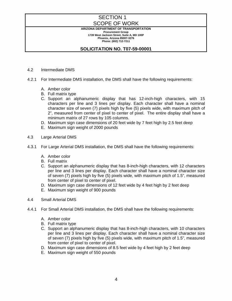
4.2 Intermediate DMS 4.2.1 For Intermediate DMS installation, the DMS shall have the following requirements:
A. Amber color B. Full matrix type C. Support an alphanumeric display that has 12-inch-high characters, with 15
characters per line and 3 lines per display. Each character shall have a nominal character size of seven (7) pixels high by five (5) pixels wide, with maximum pitch of 2”, measured from center of pixel to center of pixel. The entire display shall have a minimum matrix of 27 rows by 105 columns.
D. Maximum sign case dimensions of 20 feet wide by 7 feet high by 2.5 feet deep E. Maximum sign weight of 2000 pounds
4.3 Large Arterial DMS 4.3.1 For Large Arterial DMS installation, the DMS shall have the following requirements:
A. Amber color B. Full matrix C. Support an alphanumeric display that has 8-inch-high characters, with 12 characters
per line and 3 lines per display. Each character shall have a nominal character size of seven (7) pixels high by five (5) pixels wide, with maximum pitch of 1.5”, measured from center of pixel to center of pixel.
D. Maximum sign case dimensions of 12 feet wide by 4 feet high by 2 feet deep E. Maximum sign weight of 900 pounds
4.4 Small Arterial DMS 4.4.1 For Small Arterial DMS installation, the DMS shall have the following requirements:
A. Amber color B. Full matrix type C. Support an alphanumeric display that has 8-inch-high characters, with 10 characters
per line and 3 lines per display. Each character shall have a nominal character size of seven (7) pixels high by five (5) pixels wide, with maximum pitch of 1.5”, measured from center of pixel to center of pixel.
D. Maximum sign case dimensions of 8.5 feet wide by 4 feet high by 2 feet deep E. Maximum sign weight of 550 pounds

SECTION 1 SCOPE OF WORK
ARIZONA DEPARTMENT OF TRANSPORTATION Procurement Group
1739 West Jackson Street, Suite A, MD 100P Phoenix, Arizona 85007-3276
Phone: (602) 712-7211
SOLICITATION NO. T07-59-00001
5
5 DMS Vendor Responsibilities 5.1 For each DMS installation, the DMS Vendor shall coordinate and work closely with the
field contractor selected by the State or other political subdivisions of the State, under separate contract, and shall be responsible for the following:
5.1.1 Furnish and deliver a complete and operational DMS assembly to a specified location for
installation by a field contractor, following the receipt of purchase-order and structural drawings within the following schedule:
a. Initial order: 120 days or less. b. Subsequent orders: 90 days or less.
The State may request the DMS Vendor to delay the delivery of the DMS assembly to a date later than the 120- or 90-day period specified above at no additional cost to the State, provided such request is made within 90 days of the initial order or 60 days of subsequent orders.
5.1.2 Develop and deliver shop drawings that illustrate in detail how to mount and connect the
DMS unit to the sign structure within 30 days of placement of the order. The shop drawings must be sealed by a licensed professional engineer registered in the State of Arizona. The State and other political subdivisions of the State may adopt these drawings as standards.
5.1.3 Furnish anchor bolts along with anchor studs for attachment to the pole, and approved cabinet drawings to the field contractor 90 days in advance of the DMS delivery date.
5.1.4 The DMS Vendor shall give the field contractor a minimum of three weeks notice prior to
each requested closure, and endeavor to utilize lane closures when established for the field contractor’s activities.
5.1.5 Furnish and install a Sign Controller Unit (SCU) cabinet and all of the required
assemblies. 5.1.6 The DMS Vendor shall have a qualified representative present at the time of installation. 5.1.7 Furnish the required cabling, control and power, between the SCU and the DMS unit.
Following the installation of the control and power conductors by the field contractor, the DMS Vendor shall perform all terminations, connections, wiring to interconnect the SCU with all other components of the DMS assembly, and the power for the sign case.
5.1.8 Make all of the wiring connections in the SCU cabinet and in the DMS unit, with the
exception of power.

SECTION 1 SCOPE OF WORK
ARIZONA DEPARTMENT OF TRANSPORTATION Procurement Group
1739 West Jackson Street, Suite A, MD 100P Phoenix, Arizona 85007-3276
Phone: (602) 712-7211
SOLICITATION NO. T07-59-00001
6
5.1.9 Furnish the complete structural support mechanism (mounting brackets and
accessories) to permit the field contractor to install the DMS case on the structure. 5.1.10 Provide documentation related to the operation, installation, and maintenance of the
DMS. 5.1.11 Perform stand-alone testing. The DMS Vendor shall support the field contractor during
the system acceptance testing phase of the installation if a problem occurs within the DMS assembly.
5.1.12 Provide and install maintenance software for laptop maintenance computer (LMC). 6 Field Contractor Responsibilities 6.1 The field contractor will be responsible for the following:
6.1.1 The field contractor, for each DMS installation project, is responsible for identifying a
location, (approved by and coordinated with the Engineer) for accepting delivery of the DMSs, controllers, controller cabinets, and other shipped accessories required for complete installation and operation of the DMSs.
6.1.2 The DMS will be the responsibility of the field contractor from the moment the field
contractor begins handling the sign in any manner. It is therefore the responsibility of the field contractor to thoroughly inspect all of the equipment before the delivery truck departs and note, in writing, any damage on the bill of lading. In the event that damage is found, the Engineer must be notified immediately and the replacement procedures initiated..
6.1.3 The field contractor shall be completely responsible for storage and protection of all
materials shipped in boxes (i.e., controller, cables, etc.) in a clean, dry indoor facility from the time of delivery until installation.
6.1.4 All shipped DMS equipment shall be transported to the site, unloaded, installed, and
erected by the field contractor. 6.1.5 Furnish and install all conduits and cabling for power and communications to the SCU
cabinet. 6.1.6 Furnish and install the sign structure (e.g., overhead tubular frame) on which the DMS
shall be mounted, mounting assemblies, brackets, catwalk, and foundations. On certain occasions, the DMS may be mounted on the fascia of an existing underpass highway bridge structure. At times, the DMS may be replacing an existing DMS and be mounted

SECTION 1 SCOPE OF WORK
ARIZONA DEPARTMENT OF TRANSPORTATION Procurement Group
1739 West Jackson Street, Suite A, MD 100P Phoenix, Arizona 85007-3276
Phone: (602) 712-7211
SOLICITATION NO. T07-59-00001
7
on an existing monotube, truss or cantilever structure. 6.1.7 Provide the necessary traffic control for the installation of the DMS and support
structure. 6.1.8 Install the DMS Vendor-furnished cabling between the SCU cabinet and the DMS in
conduits furnished and installed by the field contractor, including the flex conduits entering the DMS case.
6.1.9 Construct the SCU foundation and install the SCU cabinet, including all conduits.
Cabinet installation will be complete within 48 hours of the installation of the DMS case. 6.1.10 Provide traffic control (lane closures) and a bucket truck (including an operator) for use
by the DMS Vendor’s representative during the installation and testing of each DMS. 6.1.11 Furnish the DMS Vendor with the distance between the DMS sign case and the SCU
cabinet for each site in accordance within 30 days of placement of the order. This distance will determine the approximate length of the required cables.
6.1.12 Provide the DMS Vendor with an installation date for the DMS case a minimum of four
weeks in advance of installation. 6.1.13 Deliver the DMS assembly from the storage to the installation site. 6.1.14 Establish power service by installing conduit and power conductors to the SCU cabinet.
In the event the power service is not established when the DMS Vendor is ready to perform the stand-alone test, the field contractor must reimburse the DMS Vendor all travel costs incurred, per diem, for a second field visit.
6.1.15 Establish telephone service for the dial-up DMS by providing a telephone drop in conduit
to the SCU cabinet. 6.1.16 Provide and install the fiber optic modem for the DMSs, which use single-mode fiber
optic cable, when necessary. 6.1.17 Provide and install the cellular telephone modem when this method of communications
is used. 6.1.18 Provide and install the dial-up modem when this method of communications is used.

SECTION 1 SCOPE OF WORK
ARIZONA DEPARTMENT OF TRANSPORTATION Procurement Group
1739 West Jackson Street, Suite A, MD 100P Phoenix, Arizona 85007-3276
Phone: (602) 712-7211
SOLICITATION NO. T07-59-00001
8
7 General DMS Requirements 7.1 The DMS Vendor shall provide and deliver all of the components and parts required to
provide a complete unit, including the sign case, the display matrix, ventilation, electronics, photosensors, etc. The power service to the sign location and communications to the sign location shall be provided separately. All of the signs procured under this contract shall be NTCIP-compliant (NEMA Standards 1203). The physical environment for the operation of DMSs will be harsh and subject to temperature ranges of -40° F to + 140° F.
7.2 Geographical Requirements 7.2.1 Because of the wide variations of weather and temperature in the State of Arizona, two
general categories of DMSs shall be deployed in cold and desert regions, as described below.
A. Cold Region For cold regions, the DMS shall utilize a thermostatically controlled heater inside
the sign case and in the SCU cabinet to prevent condensation and freezing of vital components. The primary installations will be in areas over 4,500 feet in elevation. The ventilation system for the sign case shall prevent dust from entering the sign. The detailed requirements for the heating system is specified in Section 8.3
B. Desert Region For desert regions, a thermostatically controlled heater shall not be utilized in the
sign case or SCU cabinet. The ventilation system for the sign case shall prevent dust from entering the sign.
7.3 Display Matrix 7.3.1 Each display module shall be easily removable and replaceable without special tools. 7.3.2 Space between pixels shall be the same horizontally and vertically and the columns shall
be perpendicular to the rows (i.e., no pitch or slant). If a proportional spacing technique is offered, variable-width characters and spacing considerations are subject to approval by the Engineer.
7.4 LED Display Modules – The following requirements shall only be met if LED signs are
proposed.

SECTION 1 SCOPE OF WORK
ARIZONA DEPARTMENT OF TRANSPORTATION Procurement Group
1739 West Jackson Street, Suite A, MD 100P Phoenix, Arizona 85007-3276
Phone: (602) 712-7211
SOLICITATION NO. T07-59-00001
9
7.4.1 Each module shall include the LED display circuit board(s). Necessary electronics shall be provided to control pixel data and read pixel status.
7.4.2 All LED modules and circuit boards shall be fully interchangeable and shall not require
any address switches or adjustment when interchanged or placed in service. 7.4.3 DMS LED modules shall be easily removed from the DMS case. 7.4.4 All LEDs shall be mounted so that their mechanical axis is normal +/- 1.00 degree to the
face of the sign to ensure brightness and uniformity over the face of the sign. The sign manufacturer shall propose a method, acceptable to the Engineer, to test the LEDs in the display modules to ensure they meet these criteria.
7.4.5 Each display module shall be replaceable individually. This is to insure that when one
pixel dies only the respective display module is replaced, not the entire sign. 7.4.6 If LEDs are not flush mounted, each pixel shall have a device attached to the printed
circuit board (PCB) to hold and protect the LEDs. These devices shall:
A. Hold the LEDs perpendicular to the display modules within 0.5 degree.
B. Prevent the LEDs from being crushed or bent during handling.
C. Protect the LEDs from damage when the display module is laid on the front surface (the side that the LED lamps are located).
D. Be easily removable from the display module PCB without any tools.
E. Not put any stress on the LEDs due to differentials of expansion and contraction
between the device and the LEDs over the herein specified temperature range.
F. Not become loose or fall off during handling or due to vibrations.
G. Not block airflow over the leads of the LEDs.
H. Securely hold each LED while allowing a gap between the device and a minimum of ninety-five percent (95%) of the body of each LED for airflow.
I. Not block the light output of the LEDs at the required viewing angle.
J. Be black in color to maximize contrast.
7.4.7 Epoxy encapsulation of the LEDs will not be permitted.

SECTION 1 SCOPE OF WORK
ARIZONA DEPARTMENT OF TRANSPORTATION Procurement Group
1739 West Jackson Street, Suite A, MD 100P Phoenix, Arizona 85007-3276
Phone: (602) 712-7211
SOLICITATION NO. T07-59-00001
10
7.4.8 The LEDs shall be protected from the outside environmental conditions, including
moisture, snow, ice, wind, dust, dirt, and UV rays. 7.4.9 LED and Pixel Characteristics 7.4.9.1 DMS pixels shall be constructed with discrete LEDs. Discrete LEDs shall conform to the
following specifications:
A. LEDs shall be non-tinted, non-diffused, high-intensity, solid-state lamps that utilize AlInGaP semiconductor technology.
B. LED lenses shall be fabricated from UV light resistant epoxy. C. The LED lens diameter shall be 0.2 inches (5 mm). Sometimes referred to as a T
1-3/4 style LED package. D. LEDs shall emit amber (yellow-orange) light that has a peak wavelength of 590 ±
4 nm. Color sorting shall be performed by the LED manufacturer. E. LEDs shall be obtained from a one-bin luminous intensity sort. A bin is defined
such that, when all LEDs from a given bin are driven with an identical forward current, the dimmest LED in the bin emits no less than half the luminous intensity of the brightest LED in the bin. Intensity sorting shall be performed by the LED manufacturer.
F. LEDs shall have a minimum half-power viewing angle of fifteen degrees (15°).
Half-power viewing angle is defined such that, at a given distance from the LED, luminous intensity measured at any point at an angle of seven and one-half degrees (7.5°) from the LEDs center axis is no less than half the luminous intensity measured directly on the LEDs center axis.
G. All LEDs used in all DMS provided for this contract shall be from the same
manufacturer and of the same part number. 7.4.9.2 Each pixel shall have a minimum initial brightness of forty (40) candela, at full bright
dimming level, over the temperature range of -40°C to +74°C (-40 °F to 165 °F). Each pixel shall maintain a brightness of thirty-four (34) candelas throughout the minimum useful life of the LEDs (100,000 hours) at a temperature of 25°C (77 °F).
7.4.9.3 The LEDs in each pixel shall be clustered to maximize long-range visibility. All pixels
shall have equal color and on-axis intensity. All pixels in all signs in this project, including the spare parts, shall have equal color and on-axis intensity. The method used to

SECTION 1 SCOPE OF WORK
ARIZONA DEPARTMENT OF TRANSPORTATION Procurement Group
1739 West Jackson Street, Suite A, MD 100P Phoenix, Arizona 85007-3276
Phone: (602) 712-7211
SOLICITATION NO. T07-59-00001
11
provide the equal color and intensity, as stated above, shall be included in the LED and pixel documentation submittals and approved by the Engineer.
7.4.9.4 Each pixel shall contain two strings of LEDs for eighteen inch (18”) character and one or
two strings for twelve inch (12”) and eight inch (8”) characters. Each pixel string shall be powered from a regulated DC power source. The failure of an LED in one string within a pixel shall not affect the operation of any other string or pixel. Pixel power drawn from the DC supplies shall not exceed one and one-half (1.5) watts per pixel, including the driving circuitry.
7.4.9.5 The LEDs shall be individually mounted and shall be easily replaceable and individually
removable using conventional electronics repair methods. 7.4.9.6 Automatically, in response to changing ambient lighting conditions as detected by the
photocells, automatic adjustment of the LED brightness shall occur in small enough increments so that the brightness of the sign changes smoothly, with no perceivable brightness change between adjacent levels. Brightness changes shall also be made remotely in response to commands received from the SCU. Provision shall be made to prevent perceivable changes in the brightness of the sign due to stray headlights shining upon the photo sensors at night.
7.4.9.7 Brightness shall be manually settable from the front panel of the SCU and remotely from
the DMS server in one percent (1%) increments (0-100%). Brightness control shall be able to be returned to automatic from the sign controller front panel, the LMC and the DMS server.
7.4.9.8 The DMS shall appear to display the entire message instantaneously. One hundred
percent (100%) pixel monitoring shall be remotely available. 7.4.10 On 18-inch-high character signs, the characters forming words shall be readable by a
person with 20/20 corrected vision within a range of 100-1000 feet in advance of the sign at an eye-height of 3.5 feet within a 15-degree cone of vision about the optical axis. On 12-inch-high character signs, the characters forming words shall be readable by a person with 20/20 corrected vision within a range of 100-600 feet in advance of the sign at an eye-height of 3.5 feet within a 15-degree cone of vision about the optical axis. On 8-inch-high character signs, the characters forming words shall be readable by a person with 20/20 corrected vision within a range of 100-400 feet in advance of the sign at an eye-height of 3.5 feet within a 15-degree cone of vision about the optical axis.
7.4.11 The cone perimeter shall be defined by its fifty percent (50%) intensity points. Non-
uniformity of brightness or color over the face of the sign or legibility of characters under these conditions shall be cause for rejection of the sign.

SECTION 1 SCOPE OF WORK
ARIZONA DEPARTMENT OF TRANSPORTATION Procurement Group
1739 West Jackson Street, Suite A, MD 100P Phoenix, Arizona 85007-3276
Phone: (602) 712-7211
SOLICITATION NO. T07-59-00001
12
7.5 Fiber Optic Display Modules – The following requirements shall only be met if Fiber Optic signs are proposed.
7.5.1 The minimum light output for pixels under normal daytime intensity setting shall be 20
candelas, as measured in the front face of the fiber. There shall be two fiber bundles terminating at each pixel. Each pixel shall be controlled by an electromagnetic shutter, which, in the closed position, shall completely block the passage of light. No light leakage shall be permitted at any light intensity level. The electromagnetic shutters shall be controlled by pulses and shall remain parked in their present position (open or closed) with zero electrical consumption after the pulse has been applied.
7.5.2 The fiber optic bundles shall be illuminated by means of quartz halogen lamps. The
lamps shall remain illuminated constantly except as follows:
A. The lamps shall be dark during sign erasure and writing periods. B. Flashing of a message shall be controlled by either flipping of the
electromagnetic device or by turning lamp(s) on and off at user selectable intervals.
7.5.3 Two (2) lamps, each rated at 6,000 hours minimum, shall be used to provide illumination
for every three 5 X 7 character modules. One lamp shall be a primary lamp and the other a backup lamp. The backup lamp shall be automatically activated in the event of failure of the primary lamp. This failure shall be recorded by the SCU for transmission to the central server. Means shall be provided to illuminate both lamps simultaneously (over bright mode).
7.5.4 The lamps and shutters shall be controlled by low voltage (48-volt maximum) AC or DC. 7.5.5 On 18-inch-high character signs, the characters forming words shall be readable by a
person with 20/20 corrected vision within a range of 100-1000 feet in advance of the sign at an eye-height of 3.5 feet within a 10-degree cone of vision about the optical axis. On 12-inch-high character signs, the characters forming words shall be readable by a person with 20/20 corrected vision within a range of 100-600 feet in advance of the sign at an eye-height of 3.5 feet within a 10-degree cone of vision about the optical axis. On 8-inch-high character signs, the characters forming words shall be readable by a person with 20/20 corrected vision within a range of 100-400 feet in advance of the sign at an eye-height of 3.5 feet within a 10-degree cone of vision about the optical axis. Operating contrast values between 6 and 25 shall be demonstrated for each lighting condition, as shown below.
[Candela (on) – Candela (off)] / Candela (off)

SECTION 1 SCOPE OF WORK
ARIZONA DEPARTMENT OF TRANSPORTATION Procurement Group
1739 West Jackson Street, Suite A, MD 100P Phoenix, Arizona 85007-3276
Phone: (602) 712-7211
SOLICITATION NO. T07-59-00001
13
7.5.6 Writing speed shall appear to write the entire sign instantaneously and shall write minimum 80 characters per second. One hundred percent pixel monitoring shall be remotely available.
7.5.7 The cone perimeter shall be defined by its fifty percent (50%) intensity points. Non-
uniformity of brightness or color over the face of the sign or legibility of characters under these conditions shall be cause for rejection of the sign.
7.5.8 Each pixel of the fiber optic DMS shall be controlled by an electromagnetic shutter
system regulated by low-voltage pulses. A minimum of two fiber optic bundles are preferred to produce readable characters. Upon receiving a momentary control pulse, the shutter shall rotate to open or close in front of the fiber optic bundles. Each shutter shall be mechanically independent and shall not require the removal of any other shutters for replacing or servicing a single shutter, and the DMS Vendor shall certify that the shutters will have an average MTBF of 70 million rotations.
7.5.9 In the closed position, no light leakage of any kind will be allowed under any condition or
at any intensity level. Once a rotation is made, the shutters shall remain in a stable position and consume no electrical power until the next control pulse is received. To assure maximum contrast ratio and legibility to the light-emitting source, each shutter mechanism shall be matte black and colorfast. To reduce the effects of fading from ultraviolet sunrays and long-term maintenance, reflective materials will not be allowed as part of the shutter assembly.
7.5.10 The fiber optic bundles shall be illuminated by means of two 50-watt quartz halogen
lamps with parabolic reflectors. The lamp assembly and fiber optic harnesses attached to each character group shall be mounted on a vibration-absorbing platform. The lamps shall operate at 10 volts or less, and shall be rated for an average service-life of 6,000 hours by the manufacturers.
7.5.11 One of the two lamps shall be designated as “primary” for normal use, and the other as
“secondary.” Both the primary and secondary lamp shall be capable of illuminating every pixel equally within the character group. It shall also be possible to non-mechanically switch from one lamp to the other in less than 100 milliseconds if the primary lamp is out, or to illuminate both lamps at full voltage if unfavorable conditions, such as intense low azimuth sunlight, occur.
7.5.12 The transformer supplying the lamps shall be field-adjustable, leaving taps on both the
primary and secondary sides. These shall be used to adjust the voltage to the rated lamp voltage for the day and over bright levels, and the reduced voltage for ambient light conditions. Both of these adjustments shall be specific.
7.5.13 The DMS controller shall continuously monitor each individual lamp, and if a primary

SECTION 1 SCOPE OF WORK
ARIZONA DEPARTMENT OF TRANSPORTATION Procurement Group
1739 West Jackson Street, Suite A, MD 100P Phoenix, Arizona 85007-3276
Phone: (602) 712-7211
SOLICITATION NO. T07-59-00001
14
lamp burns out, the secondary shall automatically take its place. When the primary lamp is replaced, it shall automatically be activated and the backup lamp extinguished.
7.5.14 The fiber optic bundles contained in the harnesses shall be manufactured using high-
quality optical fiber, possessing maximum light transmission characteristics and pixel-to-pixel uniformity. Each individual fiber optic bundle shall be sheathed with a PVC jacket to prevent damage from handling, vibration or small-radius turns. All fiber optic bundles within a character group shall converge at one of two common ends in close proximity to the lamps.
7.5.15 The output ends of the fiber optic bundles shall be firmly secured into the appropriate
apertures of each pixel on the character module, but shall be removable without the use of any special tools.
7.5.15.1 The lamps shall remain illuminated constantly except as follows:
A. During sign erasure and writing periods. B. Flashing of a message shall be controlled by either flipping of the electromagnetic
device or by turning lamp(s) on and off at user selectable intervals. C. When sign is not in use.
7.6 Power Distribution System 7.6.1 There shall be a power distribution system that connects each display module to all
power supplies and minimizes the voltage drop over the face of the sign. 7.6.2 The voltage measured at the display modules shall not vary more than fifty (50) millivolts
over all the display modules in the sign with fifty percent (50%) of its pixels on at one hundred percent (100%) intensity in each and every display module.
7.6.3 The power supplies shall be paralleled in a configuration such that one supply may
completely fail and the sign will still be supplied with enough power to run one hundred percent (100%) of all pixels at hundred percent (100%) duty cycle at 149 degrees F (65 degrees C). Failure of any single power supply shall produce no noticeable effect of the message display. The DMS manufacturer shall provide documentation as to how redundant power supply is achieved within their specific design.
7.6.4 Functioning supplies must current-share to within ten percent (10%). The combined
effect of line (97 to 135VAC) and load (10% to 100%) on the power supplies shall not exceed one percent (1.0%).
7.6.5 The efficiency of the power supplies shall be seventy-five percent (75%) or greater at
one hundred twenty (120) VAC and maximum load.

SECTION 1 SCOPE OF WORK
ARIZONA DEPARTMENT OF TRANSPORTATION Procurement Group
1739 West Jackson Street, Suite A, MD 100P Phoenix, Arizona 85007-3276
Phone: (602) 712-7211
SOLICITATION NO. T07-59-00001
15
7.6.6 The power supplies shall have a power factor of 0.95 or greater at one hundred twenty
(120) VAC from fifty percent (50%) to one hundred percent (100%) of maximum load. 7.7 Photocells 7.7.1 The sign shall incorporate a means of changing the lighting level provided by the lamps
automatically in response to ambient lighting conditions as detected by photocell, and remotely in response to commands received from the central control system. Three photocells shall be installed on each sign. These devices shall permit automatic light intensity measurement of light conditions at each sign location. These photocells shall be mounted in a manner to measure front, rear, and ambient light conditions. The mounting devices for the photoelectric cells shall allow full adjustment of the cell orientation.
7.7.2 The photoelectric cells shall be located such that they are easily accessible for
maintenance. 7.7.3 These devices shall direct the SCU to modify the intensity of the light produced by the
pixel elements. 7.7.4 If one or more photocells fail, the sign shall remain in the normal brightness mode and
an error message shall be sent to the SCU. The SCU shall transmit the failure state back to the DMS server.
7.8 Pixel Status Feedback 7.8.1 Two separate types of pixel status feedback shall be provided to the DMS server from
the SCU or LMC for LED type signs. These include a pixel test and a pixel read.
A. Pixel Test: The pixel test shall be performed from the DMS server or LMC on command and automatically once a day. During a pixel test, the full operational status of each string of LEDs in each pixel shall be tested and then transmitted to the DMS server or LMC. This pixel status test shall distinguish the difference between half out, full out; half stuck-on and fully stuck-on pixels. A list of defective pixels shall be provided, listing pixel status, line number, module number, column number and row number for each defective pixel. The pixel test may briefly disturb the displayed message for less than 0.5 seconds.
B. Pixel Read: The pixel read shall be performed when a message displayed and
during every sign poll from the DMS server or LMC. The pixel read shall perform a real-time read of the displayed message and shall return the state of each pixel to the DMS server through the SCU as it is currently displayed to the motorist,

SECTION 1 SCOPE OF WORK
ARIZONA DEPARTMENT OF TRANSPORTATION Procurement Group
1739 West Jackson Street, Suite A, MD 100P Phoenix, Arizona 85007-3276
Phone: (602) 712-7211
SOLICITATION NO. T07-59-00001
16
including any errors. This shall allow the DMS server operator to see what is visibly displayed to the motorist on an individual pixel basis. During a pixel read, the state of each pixel (full-on, half-on or off) in the sign shall be read by the SCU to allow the DMS server or laptop computer to show the actual message, including static, flashing and alternating messages, that is visibly displayed on the sign in a WYSIWYG format. This pixel reading shall take place while a message is displayed on the sign without disturbing the message in any way. Any flashing, flickering, blinking, dimming, or other disturbance of the message during this pixel read shall be cause for rejection of the sign.
C. The pixel read shall be an actual real-time read of the current flowing through
each string of LEDs at the time of the associated sign poll or message download and shall not be accomplished by simulating errors based on the last pixel test.
7.9 Text and Character Characteristics 7.9.1 The signs shall be capable of displaying ASCII/ANSI character codes 32 through 126
(which includes all English upper and lower case letters, punctuation characters, such as: .,” ” ’ ! ?, other characters, such as: # & + - / () < > ^ ~ $ % * and digits from 0 to 9) at any location in a message line. If required, the sign shall be able to substitute a special graphics character for any of these characters.
7.9.2 The DMS shall be able to display:
A. Standard Double Text Line Alphanumeric (5 x 7 nominal pixel resolution per character).
B. Compressed Double Text Line Alphanumeric on full matrix signs (4 x 7 nominal
pixel resolution per character). C. Double Text Line Alphanumeric on full matrix signs (7 x 11 nominal pixel
resolution per character). D. Single Text Line Alphanumeric on full matrix signs (11 x 24 nominal pixel
resolution per character). 7.9.3 The spacing options shall be one, two or three pixel columns on full matrix signs. 7.9.4 Text justification (left, center, right, top and bottom) shall be provided. 7.9.5 On full matrix signs, the separation between the last column of one module and the first
column of the next shall be equal to the horizontal distance between the columns of a single display module.

SECTION 1 SCOPE OF WORK
ARIZONA DEPARTMENT OF TRANSPORTATION Procurement Group
1739 West Jackson Street, Suite A, MD 100P Phoenix, Arizona 85007-3276
Phone: (602) 712-7211
SOLICITATION NO. T07-59-00001
17
7.9.6 On full matrix signs, the separation between the last row of one module and the first row
of the next shall be equal to the horizontal distance between the rows of a single display module.
8 Dynamic Message Sign Case 8.1 Construction 8.1.1 All DMS cases shall be dustproof and watertight. The Freeway DMS shall be designed
for attachment to an overhead sign support structure of type and design indicated in ADOT Standard Drawing No. SD 9.50 for Variable Message Sign Tubular Frame. All welding shall be performed in accordance with ANSI/AWS D1.2 Structural Welding Code for Aluminum.
8.1.2 All DMS cases shall be constructed of unfinished aluminum, with all seams continuously
welded. The DMS shall be fitted with knockouts for two three-inch conduits and one two-inch conduit.
8.1.3 The sign face shall be manufactured of one-quarter-inch non-glare polymethacrylate,
exceeding the AASHTO wind loading requirements. For substitutes, the DMS Vendor shall submit one sample (12” X 12”) of the proposed materials together, with a description of the materials attributes along with the proposal for review. All front face panel surfaces not directly in front of a light-emitting pixel, shall be covered with a flat black material to reduce glare and increase the contrast ratio. Areas of the sign face that need not be transparent to display the message shall be covered with an ultraviolet stabilized dull matte film to minimize glare. The front faces shall have gaskets to prevent the entry of water, dust, and dirt, and shall be easily removable by a single person.
8.1.4 Differential expansion of the sign case and the display panel shall not cause damage to
components. Waterproof measures shall be implemented for all sign face panels. To allow for the vacuum effect of the passage of large trucks, the sign face shall be designed for and shall withstand a negative (outward) pressure of 50 percent of the design inward wind pressure.
8.1.5 The mounting hardware for the entire sign or for each line of the sign shall be designed
to provide a nominal downward tilt of four degrees about the horizontal axis with the top of the sign forward. Means shall be provided to allow adjustment of plus-or-minus six degrees about the horizontal axis in one degree increments. The sign shall operate properly at all of these positions.
8.1.6 The sign housing shall come equipped with slotted aluminum extrusions mounted across
the back of the sign in the vertical position. Each extrusion shall accept manufacturer-

SECTION 1 SCOPE OF WORK
ARIZONA DEPARTMENT OF TRANSPORTATION Procurement Group
1739 West Jackson Street, Suite A, MD 100P Phoenix, Arizona 85007-3276
Phone: (602) 712-7211
SOLICITATION NO. T07-59-00001
18
supplied stainless steel mounting bolts and nuts with the heads fitted to slide within the extrusion for complete adjustability in the vertical direction. This configuration shall allow the sign to be mounted to horizontal members on the structure and mounting plates attached to “U-bolts” or hardware supplied by others.
8.1.7 The door lock and key system shall match that provided for the SCU cabinet. A door
switch and contact closure shall be provided to send a “DMS case door open” alarm to the SCU.
8.2 Ventilation 8.2.1 For signs installed in the desert regions of the State, the ventilation system shall be
designed such that the system protects the sign and its contents from malfunctions due to heat.
8.2.2 All sign cases shall be equipped with a positive pressure ventilation system to draw air
into the case through filtered drain holes and inlets. The pressure created shall be sufficient to prevent air from entering the sign enclosure, except through filtered inlets. Changeable filtration devices shall be provided at drain holes and at all points where forced air enters the enclosure. Filters shall be cleanable and changeable from within the sign housing without the use of tools.
8.2.3 If a multiple fan system is used, the fans shall be thermostatically controlled and the
single fan needed to provide the positive pressure shall be automatically reselected every eight hours to extend the mean-time-between-failures. If a fan fails, it shall automatically be deselected and another fan selected, and an error message shall be sent to the SCU. The SCU shall transmit the failure state back to the central server on the next poll cycle.
8.2.4 The ventilation system shall be thermostatically controlled, and of sufficient quantity and
size, as to not permit temperatures inside the enclosure to exceed 150°F, when personnel are not present, the sign is in full sun, and all equipment in operation. Air conditioning shall not be permitted. Current temperature readings for inside the case shall be transmitted to the central server via the SCU.
8.2.5 For freeway and intermediate size signs, the DMS Vendor must replace all inlet filters
with clean/new ones on-site per manufacturers’ recommendation or quarterly, whichever comes first, for a period of five years at no additional cost to the Department. The DMS Vendor will be responsible for all costs related to this requirement, including but not limited to the following: Travel, per diem, labor, material, equipment, on-site labor, on-site material, on- site equipment, access to the signs and traffic control.
8.3 Heating

SECTION 1 SCOPE OF WORK
ARIZONA DEPARTMENT OF TRANSPORTATION Procurement Group
1739 West Jackson Street, Suite A, MD 100P Phoenix, Arizona 85007-3276
Phone: (602) 712-7211
SOLICITATION NO. T07-59-00001
19
8.3.1 For signs installed in the cold regions of the State, the sign case shall protect the sign
and its contents from malfunctions due to cold weather. Thermostatically controlled heater strips shall be provided to keep the front face from condensation and prevention of the vital components from freezing. In addition, the sign case shall have adequate heating to raise the temperature 32°F over ambient during maintenance.
8.3.2 The heaters shall be controllable remotely from either the central computer or the LMC
connected at the SCU, and manually from inside the sign using a wind-up timer. 8.4 Lighting 8.4.1 The DMS Vendor shall provide lighting along the full length of the interior of the sign
case. 8.5 Laptop Cable 8.5.1 A cable shall be furnished to allow for the LMC operation of the SCU from a ground or
pole mounted controller cabinet. The cable shall be of extended range and shielded, to be installed in conduit from the SCU to the controller cabinet. At the SCU, the cable shall be terminated with a connector that matches with the LMC interface connector of the SCU. In the controller cabinet, the cable shall be terminated with a connector that matches with the LMC serial port. Sufficient slack shall be provided in the controller cabinet for reaching all areas within the cabinet.
8.6 Duplex Outlets 8.6.1 120 VAC, duplex convenience outlets shall be provided with integral ground-fault circuit
interrupter (GFCI) and shall be protected by a circuit breaker. 8.6.2 The receptacles shall be NEMA Type 5-15 R and shall have a spring-loaded cap and be
positioned so that no electrical hazard shall exist when used by service personnel. 8.6.3 One duplex outlet shall be located on each end of the DMS case and at eight (8) feet
(2.4 meter) minimum spacing along the sign case for freeway and intermediate type signs DMS assemblies.
8.7 Transparent Anti-Glare Sign Case Front Panels 8.7.1 The sign face shall be manufactured of non-glare polycarbonate panels of GE Lexan
Type 5300-12 and a KYNAR 500 coated aluminum mask over a clear glazing, or a substitute identified in the product submittal as an equal with a minimum thickness exceeding AASHTO design requirements for a wind velocity of 90 mph (145 km/h).

SECTION 1 SCOPE OF WORK
ARIZONA DEPARTMENT OF TRANSPORTATION Procurement Group
1739 West Jackson Street, Suite A, MD 100P Phoenix, Arizona 85007-3276
Phone: (602) 712-7211
SOLICITATION NO. T07-59-00001
20
8.8 The DMS case shall be provided with all cables securely clamped or tied within the DMS
case. No adhesive attachments will be allowed. 8.9 The complete sign case shall be designed and manufactured under the supervision and
control of the DMS sign manufacturer. 9 Sign Controller Unit (SCU) 9.1 The SCU shall receive commands to place messages in its memory buffer, confirm
message content, and display a stored message on the sign. The SCU shall consist of a solid-state electronic device dedicated to the operation of the DMS.
9.2 The rated life of all components in the SCU shall be a minimum of ten years under 24-
hour-a-day operation. Semiconductor devices shall be used exclusively, and solid-state components shall be standard production types and readily available.
9.3 Communications Interface 9.3.1 The SCU shall be able to communicate with the central server and the laptop
maintenance computer (LMC) using the following two separate EIA-232 serial interfaces:
A. An EIA-232 serial interface functioning as the primary communications path to the DMS server.
B. An EIA-232 serial interfaces functioning as the communications path to the LMC.
This connector shall be easily accessible via the front of the cabinet and located either integrally in the face of the SCU or as a separate port in the cabinet. If the SCU is located internal to the DMS case, the port must be accessible via the bottom of the DMS structure.
9.3.2 The SCU shall be able to communicate with the central server using the following types
of communications circuits connected to the EIA-232 serial port: A. An EIA-232 serial interface to a fiber optic modem furnished and installed by the
Field Contractor. B. An EIA-232 serial interface to a plain old telephone service (POTS) dial-up line
modem furnished and installed by the Field Contractor. C. An EIA-232 serial interface to a General Packet Radio Service (GPRS) or Code
Division Multiple Access (CDMA) wireless network modem furnished and installed by the Field Contractor.

SECTION 1 SCOPE OF WORK
ARIZONA DEPARTMENT OF TRANSPORTATION Procurement Group
1739 West Jackson Street, Suite A, MD 100P Phoenix, Arizona 85007-3276
Phone: (602) 712-7211
SOLICITATION NO. T07-59-00001
21
D. An EIA-232 serial interface to a twisted-wire pair (TWP) copper cable modem
furnished and installed by the Field Contractor. 9.3.3 The SCU shall be equipped with at least one Ethernet interface for future use. 9.3.4 If the communications system utilizes copper wire, the DMS supplier shall also furnish
adequate lightning protection for termination inside the cabinet. 9.4 SCU Software 9.4.1 The SCU software shall make the SCU operate the DMS; monitor the status of all sign
hardware; and communicate with the central server and LMC. 9.4.2 The SCU software shall accomplish the following sign operations:
A. Cause the sign to display static messages, flashing messages, and two alternating messages formed by two static or flashing messages. The time required to display the longest possible message shall not exceed 0.8 second from a blank state, and 2.0 seconds from any non-blank state.
B. Erase the previous message prior to the writing of a new message. C. For alternating (two-phase) messages, provide selection of the display time for
each phase and the blank-out time between messages in tenths of a second between 0.3 and 12.7 seconds.
D. Provide selectable message display time, including unlimited display time for
each message. E. Cause all pixels to be activated at selectable intervals (programmed via the LMC)
as a self-maintenance measure. The DMS Vendor shall develop a test pattern and receive approval from the Engineer before installation.
F. Provide diagnostic routines that report failures and malfunctions in the sign and
in the SCU upon inquiry from the central control system. Detected failure conditions shall be automatically returned to the central control system.
9.5 Controller Address 9.5.1 A unique address shall be assigned to each SCU. All commands from the central
control location to this sign will be prefaced with this address. The SCU shall compare this received address with the assigned address and shall accept the command only if

SECTION 1 SCOPE OF WORK
ARIZONA DEPARTMENT OF TRANSPORTATION Procurement Group
1739 West Jackson Street, Suite A, MD 100P Phoenix, Arizona 85007-3276
Phone: (602) 712-7211
SOLICITATION NO. T07-59-00001
22
the addresses match. 9.6 Message Storage and Display 9.6.1 The SCU shall have sufficient memory to store a minimum of sixteen (16) two-phase
messages, with each consisting of up to three (3) lines with 18 characters. A two-phase message is defined as a continuous statement that requires two separate displays on the sign face. Either EPROM or EEPROM shall be used to store messages in the SCU. Internal circuitry shall be provided to replace stored messages with new messages received from the central server and LMC. A long-life battery shall back up the SCU’s RAM such that no loss of memory occurs during power outages of 24-hour duration.
9.6.2 Upon external command, the SCU shall allow any message stored in memory to be
displayed on the sign face, or replaced with a new message. The SCU shall receive messages through the communications unit from the central server or LMC, and shall store the received messages in its memory buffer. The SCU shall transmit confirmation of message content back to the central server or LMC for received messages and stored messages when requested to do so.
9.6.3 During uploading and downloading of messages by the central server or LMC, normal
sign operations shall not be suspended and current message display shall not be interrupted.
9.7 Message Display Time 9.7.1 Upon termination of the display time for a message, the controller shall either blank the
sign (no lamps lit and shutters closed), or place the sign in a neutral condition (a predefined message selected for inactive periods).
9.7.2 Message writing and erasure shall be accomplished in a left-to-right column scan, which
shall appear to be simultaneous for all characters and shall be at a minimum scan rate of 54 characters per second.
9.7.3 In the event of a loss of communications with the central server, the SCU shall maintain
the originally commanded message for a user-specified period, after which time the sign shall go blank pending the resumption of communications. The period shall be adjustable over the range of 0 to 255 minutes.
9.7.4 For each message, the operator shall be able to direct the controller to set a display time
as either being unlimited or defined. If defined, it shall have a maximum of at least 64,800 minutes or 45 days.
9.8 The SCU shall be able to display the following message types:

SECTION 1 SCOPE OF WORK
ARIZONA DEPARTMENT OF TRANSPORTATION Procurement Group
1739 West Jackson Street, Suite A, MD 100P Phoenix, Arizona 85007-3276
Phone: (602) 712-7211
SOLICITATION NO. T07-59-00001
23
9.8.1 Static Message 9.8.2 Flashing Message 9.8.2.1 Two-phase flashing messages shall be displayed with maximum of all possible
characters in each phase. 9.8.2.2 For flashing messages, the central server or LMC operator shall be able to select the
flash ON and flash OFF time in 0.1-second increments from 0.3 to 1.5 seconds. 9.8.3 Alternating Message (two-state) 9.8.3.1 For alternating messages, selected portion of the chosen sign shall display two
messages alternately with a repetition interval from one to ten seconds. The duration of each message displayed shall be independently selectable in 0.1-second increments.
9.9 Message Status Monitoring 9.9.1 The SCU shall transmit a return message to the central server whenever it receives a
valid transmission and when it is being addressed. The return message shall be in ASCII. The DMS Vendor, subject to the Engineer’s approval, shall select the format of the return message. In general, the return message format shall contain the sign address, sign message being displayed, mode of operation, contents of any message stored in memory (if required from the central control system), and the presence and type of error detected.
9.10 Failure Detection 9.10.1 The SCU shall detect the following failures:
A. Power supply monitor circuitry to detect power failure
B. Data transmission errors
C. Communications
D. Fan E. Heater (cold regions only)
F. Photocell

SECTION 1 SCOPE OF WORK
ARIZONA DEPARTMENT OF TRANSPORTATION Procurement Group
1739 West Jackson Street, Suite A, MD 100P Phoenix, Arizona 85007-3276
Phone: (602) 712-7211
SOLICITATION NO. T07-59-00001
24
G. Lamp
H. Shutter, if fiber optic sign is proposed
I. SCU case or DMS case opened-door 9.11 Driving Electronics 9.11.1 The driving electronics shall generate the signals to the devices controlling the pixels to
be illuminated. These signals shall be based on commands received from the SCU. 9.11.2 The driving circuitry may be located in the sign case, or be in a separate cabinet at
ground level. A statement describing the selected method and its advantages shall be included in the DMS Vendor’s proposal.
10 Sign Control Unit (SCU) Cabinet 10.1 The proposer shall offer one of the following two SCU cabinet options: 10.1.1 A ground mounted cabinet (separate from the DMS Case) housing the SCU,
communications modem/transceiver, LMC pull-out shelf, power distribution assembly (for the SCU, communications modem/transceiver, and GFCI maintenance outlets) and main power service disconnect/breakers.
10.1.2 A pole mounted cabinet for communications modem/transceiver, LMC pull-out shelf,
power distribution assembly (for the communications modem/transceiver and GFCI maintenance outlets) and main power service disconnect/breakers. The pole mounted cabinet shall be mounted on the sign structure. In this situation, the SCU will be housed in the DMS Case.
10.2 The DMS Vendor shall furnish fully equipped DMS SCU cabinets, to be installed by the
field contractor. The controller rack is to be located at a height of between four feet and six feet above the ground. For each DMS installation, the cabinet is to be placed at a distance from the DMS to keep the cable length less than the maximum desirable of 150 feet. Conditions that require the cable length to be greater than 150 feet will be brought to the attention of the DMS Vendor.
10.3 The outer cabinet shall be made of 10-gauge, welded, unpainted aluminum with
minimum dimensions of approximately 49 inches high by 30 inches wide, by 24 inches deep, with ventilation louvers located on the front and back to ensure natural convection cooling of all enclosed materials. A pullout shelf shall be provided and stored within the cabinet for the placement of a laptop computer.

SECTION 1 SCOPE OF WORK
ARIZONA DEPARTMENT OF TRANSPORTATION Procurement Group
1739 West Jackson Street, Suite A, MD 100P Phoenix, Arizona 85007-3276
Phone: (602) 712-7211
SOLICITATION NO. T07-59-00001
25
10.4 Each ground mounted cabinet shall be supplied with the following as minimum:
A. Fans and thermostat. B. Sign Controller Unit. C. Communications interface (modem or transceiver). D. Main power supply and distribution system. E. Overvoltage protection. F. Three fully adjustable photosensor controls, allowing adjustment from the inputs of
the three photosensors on the sign. G. Cabinet label per Engineer’s requirement. H. EIA equipment rack. I. Cabinet electrical diagram and drawing storage. J. Cabinet weatherproofing. K. Anchor bolts, anchor studs, and approved cabinet drawings (to be delivered to the
field contractor 90 days in advance of cabinet delivery). L. One 15-amp, 120-VAC GFCI controlled duplex service outlet. M. Lightning protection and termination for the communications lines. N. A 250-watt resistance heater controlled by an adjustable thermostat (cold regions
only). O. A telephone block and two telephone jacks. P. Circuit breaker, RFI suppressor, and power input junction terminal. Q. Two unused 20-amp, 120-VAC circuit breakers. R. Termination panel and termination blocks. S. Harnesses and connectors. T. Main circuit breaker box and a radio interface filter. U. The DMS Vendor shall design the layout of the contents of this cabinet.
10.5 Doors 10.5.1 All SCU cabinet doors shall withstand a 200-pound vertical load applied anywhere on
the door. The doors shall have catches to hold the doors open at 90 and 135 degrees. The doors shall have gaskets in channels or “L” brackets with a minimum 0.37-inch gasket made of non-absorbent material and shall maintain its resiliency after long-term exposure to the outdoor environment.
10.5.2 Doors shall be provided with an integral locking system that utilizes a CORBIN No. 2-
type lock, wherein a key is required to lock the door, and removable only in the locked position. The DMS Vendor shall provide four identical keys that shall open the locks for both cabinets.
10.5.3 A door switch and contact closure shall be provided to send a “cabinet door open” alarm
to the SCU.

SECTION 1 SCOPE OF WORK
ARIZONA DEPARTMENT OF TRANSPORTATION Procurement Group
1739 West Jackson Street, Suite A, MD 100P Phoenix, Arizona 85007-3276
Phone: (602) 712-7211
SOLICITATION NO. T07-59-00001
26
10.6 Filter 10.6.1 A removable air filter shall be housed behind the door vents. The filter shall be ECO-AIR
Products E355 Pleated Paper or approved equivalent. 10.7 Ventilation and Heater 10.7.1 Sign controller cabinet ventilation shall consist of two 120-VAC, 60 Hz, tube axial
compact-type fans. Each fan’s free delivery airflow shall be sufficient to keep the inside cabinet temperature within the operating range of the control equipment. Each fan’s airflow shall not be less than 100 cubic feet per minute. The magnetic field of the fan motor shall not affect the performance of the control equipment. The fan bearings shall operate freely within the environmental standards specified herein. The fan assembly shall not crack, creep, warp, or have bearing failure within a five-year-rated duty cycle. The maximum noise level shall not exceed 40 dB. The fan assembly shall be corrosion-resistant.
10.7.2 An adjustable snap action thermostat shall control each cabinet. The thermostat’s turn-
on setting shall be adjustable from 90° F to 120° F. Each fan shall be fused. Each cabinet fan assembly shall be mounted inside the sign controller cabinet.
10.7.3 Thermostatically controlled heater shall be placed in the SCU cabinet of every DMS.
The heater and cabinet fans shall be activated by the thermostat when temperatures drop below a threshold established by the communications equipment and turned off when temperatures are five degrees higher than the minimum threshold. The heater shall be capable of maintaining the minimum temperature threshold indefinitely throughout the cabinet.
10.8 Lighting 10.8.1 One 18-inch fluorescent light with door-switch-actuation per door shall be used. The
fixtures shall be mounted on the inside top of the cabinet near the front edge and rear edge of the roof so that the front or rear of the control equipment is illuminated when the corresponding door is open. Door-actuated, refrigerator-type, normally closed, durable push-button-type switches shall automatically turn the associated light fixture on and off when the door is opened and closed.
10.8.2 The lamps shall light the front face of the controller and the rear of the cabinet, and be
positioned such that they do not shine into the technician’s eyes. 10.9 Rack 10.9.1 The cabinet shall contain a 19-inch EIA rack for the front and back of the cabinet, with

SECTION 1 SCOPE OF WORK
ARIZONA DEPARTMENT OF TRANSPORTATION Procurement Group
1739 West Jackson Street, Suite A, MD 100P Phoenix, Arizona 85007-3276
Phone: (602) 712-7211
SOLICITATION NO. T07-59-00001
27
consideration for future add-ons. The angles shall comply with EIA RS-310B. The cage shall be retractable or shall be bolted at four points both top and bottom to the cabinet via the housing cage supports and associated spacers.
10.10 Shelves 10.10.1 Shelves shall be rack-mounted with ball-bearing slides capable of supporting 20
pounds. A minimum of three rack units of clearance shall be provided above the shelf, designated for communications equipment.
10.11 Serial Number 10.11.1 Cabinets shall be supplied with a serial number unique to the manufacturer. The
number shall be engraved on a metalized Mylar plate that is permanently attached to the inside, upper right-side wall of the cabinet.
10.12 Surge Protection and Lightning Protection 10.12.2 The sign controller cabinet shall be equipped with a surge protector conforming
to the requirements of ADOT Standard Specifications for Road and Bridge Construction, and shall operate within temperatures ranging from -40° F to + 140° F. All cabinet wiring shall also conform to ADOT Standard Specifications for Road and Bridge Construction. Power line surge protectors shall be installed between both line conductors and equipment ground. All conductors entering and leaving the cabinet shall be protected by surge protectors and lightning arrestors. Data lines between the SCU and the sign case shall also contain surge protection. Power line surge protection (e.g., GPTS 120 TLC 20P or EDCO 1210 SHA) shall conform to the following requirements: A. Peak surge current occurrences 20 minimum B. Peak 8 X 20 msec wave shape 20K amps C. Response 250 maximum D. Maximum current at 120-VAC, 60 Hz 10 amps E. Series inductance 200 microhenries F. Temperature NEMA TS-1 G. Maximum dimensions 3.3-inch x 15.0-inch x 2.6-inch
10.12.3 The power line surge protector shall be a two-stage device that allows the
connection of radio interference filter in the circuit between the stages. Each cabinet shall be equipped with one or more radio interference filters in the power line surge protector. The filter shall provide attenuation of at least 50 dB over a range of 50 kHz to 20 MHz.
10.13 Duplex Outlet

SECTION 1 SCOPE OF WORK
ARIZONA DEPARTMENT OF TRANSPORTATION Procurement Group
1739 West Jackson Street, Suite A, MD 100P Phoenix, Arizona 85007-3276
Phone: (602) 712-7211
SOLICITATION NO. T07-59-00001
28
10.13.1 A 120-VAC convenience outlet shall be provided with integral ground fault interrupt and shall be protected by a circuit breaker. The receptacles shall be NEMA Type 5-15 R, shall have a spring-loaded cap, and shall be positioned so that no electrical hazard shall exist when used by service personnel.
10.14 Grounding 10.14.1 The field contractor shall ground the cabinet per ADOT requirements. The DMS
Vendor shall verify and inspect all existing ground connections to ensure acceptability for the installation and operation of the DMS control equipment. The grounding system in the cabinet shall be divided into separate and distinct circuits, connected together at a single point. This requirement shall eliminate ground loops, adequately direct transients to ground, and allow for testing of the separation between the grounding circuits by temporarily removing the jumpers.
10.15 Cabling 10.15.1 The DMS Vendor shall be responsible for furnishing all control and power cables
between the DMS and the SCU to the field contractor for installation. Following installation of the control and power conductors by the field contractor, the DMS Vendor shall perform all terminations, connections, and wiring to interconnect the SCU with all other components of the DMS assembly, including all connections internal to the DMS case and power for the sign case.
10.16 Power Supply 10.16.1 The power supply shall provide power for all equipment in the sign controller
cabinet and the DMS. The incoming power to the SCU shall be 120/240-VAC, 60 Hz. The total power requirement for the sign and SCU shall not exceed 5,000 watts during the operation of a user-selected message with all characters being displayed to the public. An average of 15 pixels per character will be used for calculation verification. The equipment in the sign controller cabinet shall require no more than 500 watts for operation, excluding heater operation.
10.17 Pole Mounted Cabinet Requirements 10.17.1 The pole mounted cabinet shall be used in conjunction with the freeway size
sign. The cabinet may be ground mounted, with approval of the Engineer. 10.17.2 The pole mounted cabinet shall have two (2) EIA-232 serial ports; one for the
communications medium (i.e. fiber optic modem, dial-up modem, cellular modem, etc.) and one for the laptop maintenance computer (LMC).

SECTION 1 SCOPE OF WORK
ARIZONA DEPARTMENT OF TRANSPORTATION Procurement Group
1739 West Jackson Street, Suite A, MD 100P Phoenix, Arizona 85007-3276
Phone: (602) 712-7211
SOLICITATION NO. T07-59-00001
29
10.17.2 The pole mounted cabinet must be located within 50 feet from the SCU, with the top of the cabinet no more than 6 feet above ground.
10.17.3 The pole mounted cabinet shall contain a laptop pull-out or drop down shelf or
approved equivalent. 10.17.4 The pole mounted cabinet shall have a power service disconnect switch.
11 Power Requirements 11.1 The incoming power to the DMS assembly shall be single-phase, 120/240 ±15 VAC, 60
±3 Hz. The total power consumed from the power distribution assembly (PDA) within for the DMS assembly shall not exceed five thousand (5,000) watts during the operation of the sign, with all pixels being displayed, and with all ventilation and heaters on.
11.2 Inside the DMS case, all 120/240 VAC service lines shall be independently protected by
thermomagnetic circuit breaker(s). 11.3 All 120/240 VAC wiring shall be installed in conduit, pull boxes, raceways or control
cabinets as required by the National Electrical Code (NEC). No 120/240 VAC wiring shall be exposed to the inside or outside of the sign case, sign structure, or SCU cabinet.
11.4 All DMS equipment shall be grounded per the NEC. 12 Communications 12.1 All communications are accomplished through the SCU software. Since this contract is
intended for the use of the State, counties and cities, the manufacturer’s sign will be required to operate from multiple software platforms. The sign shall be able to interpret all public NTCIP requests from the following central software: Mercure, Skyline, Addco, and Camera Cameleon.
12.2 The dial-up communications between the SCU and the central server, laptop
maintenance computer (LMC) shall be via EIA-232 using dial-up landline modems, or CDMA or GPRS modems.
12.3 For dial-up communications, the data transmission rate shall be configurable to select
1.2 kbps to 56 kbps. The communications protocol between the DMS controller and the central server shall meet the NTCIP Application Layer Standard as defined by the standards contained in the following Table.

SECTION 1 SCOPE OF WORK
ARIZONA DEPARTMENT OF TRANSPORTATION Procurement Group
1739 West Jackson Street, Suite A, MD 100P Phoenix, Arizona 85007-3276
Phone: (602) 712-7211
SOLICITATION NO. T07-59-00001
30
NTCIP STANDARDS Abbreviated
Number Full Number
(NEMA Number) Title Known Amendments
NTCIP 1101 NTCIP 1101:1997 (NEMA TS 3.2-1996)
Simple Transportation Management Framework Amendment #1 dated November 2, 1998.
NTCIP 1201 NTCIP 1201:1997 (NEMA TS 3.4-1996) Global Object Definitions Amendment #1 dated November 2, 1998.
NTCIP1203 NTCIP 1203:1997 (NEMA TS 3.6-1997)
Object Definitions for Dynamic Message Signs
NTCIP 2103 NTCIP 2103v01.03 (Draft) Point-to-Point Protocol using RS 232 Subnetwork Profile
NTCIP 2202
NTCIP 2202v01.08 (Recommended)
(NEMA TS 3.Internet v99.01.03)
Internet Transport Profile
12.4 Central server shall be the primary computer for communications with its associated
signs. Any other computer that is used to display a message on a DMS shall do so by dialing the central server first unless it is absolutely necessary to communicate with the sign directly.
12.5 The SCU software shall provide diagnostic routines that report failures and malfunctions
in the sign and in the SCU upon inquiry from the central server or the LMC. Detected failure conditions shall be automatically returned to the central server. Using the LMC connected to a parallel printer and to the SCU, the entire SCU database shall be printed upon request.
12.6 For the ADOT FMS projects, the DMS SCU shall be connected to single-mode fiber
optic cable. The FMS communications shall include optical transceiver, operating at 9600 baud, to be furnished and installed by the field contractor.
13 Environmental 13.1 All field equipment shall remain fully functional without any decrease in performance
over an ambient temperature range of -40° F to + 140° F and an outdoor ambient humidity range of 5% to 95%, noncondensing.
13.2 All field equipment shall be designed to and shall withstand 90-mph winds with 30% gust
factors. 13.3 All field equipment enclosures shall be designed to and shall withstand the effects of
sand, dust, and hose-directed water. All connections shall be watertight. The interior DMS temperature shall not exceed 150° F. Ambient temperatures are expected to exceed 120° F in southern Arizona.

SECTION 1 SCOPE OF WORK
ARIZONA DEPARTMENT OF TRANSPORTATION Procurement Group
1739 West Jackson Street, Suite A, MD 100P Phoenix, Arizona 85007-3276
Phone: (602) 712-7211
SOLICITATION NO. T07-59-00001
31
14 Spare Parts 14.1 The parts shall be available to keep the system operational for ten years after the
equipment acceptance (i.e., the date of passing the system acceptance test). With this contract in place, the Department shall be able to purchase a number of spare parts for future use in accordance with the Vendor’s cost proposal.
14.2 The DMS Vendor shall submit a current parts list with prices for all equipment supplied
by Vendor. The list must be the most current, published list by the DMS Vendor. 14.3 The following is a general list of spare parts for which the DMS Vendor must provide
prices as part of the initial order for each type of sign the DMS Vendor is proposing on. For additional parts, which are not listed below, but required for the Vendor’s sign system, the DMS Vendor must also provide prices.
A. Each electronic circuit board required for controlling the sign. B. Dial-up modem. C. All relays. D. Character module group. E. Full matrix display module F. Door assembly. G. Pressure fan. H. Fan filter. I. All interface terminal boards/blocks used in the sign and controller cabinet. J. Each type of circuit breaker. K. Photocells and photo detectors. L. Sign housing light fixtures and bulbs. M. Cabinet light fixtures and bulbs. N. Cabinet heater and thermostat. O. Sign heater strips. P. Door switches. Q. Transformers. R. Individual character boards (5 X 7 matrix). S. Fiber harness, if fiber optic. T. Lamp assembly. U. 12 VAC RFI filter and lightning arrestor blocks. V. Cable harness between each electronic circuit board and terminal block. W. Completely equipped ground or pole mounted cabinet for each of the types of signs
the DMS Vendor is proposing on. X. Shutter. Y. Halogen lamp. Z. Sign controller unit.