frequency scanning interferometry traceable 3d...
TRANSCRIPT
Frequency Scanning Interferometry – traceable 3D coordinate
metrology
Ben Hughes, Mike Campbell, Andrew Lewis
LUMINAR End of Project Meeting
2016, 19th May, NPL
Welcome to the National Physical Laboratory

Outline
Introduction
NPL’s Proposed Coordinate Metrology System
Results
Summary & Conclusions
Future Work

Introduction
• How good is my instrument?
• How can I be sure my calibration is still valid?
• What’s my measurement uncertainty?

Introduction
Objective is to make a CMS that is:
1. As accurate as possible
2. Measures multiple points simultaneously
3. Self-calibrating - built-in compensation for systematic errors
4. Has built-in traceability to SI metre
5. Gives on-line uncertainty estimation
Current project focus on proof-of-principle
Outline
Introduction
NPL’s Proposed Coordinate Metrology System
Results
Summary & Conclusions
Future Work
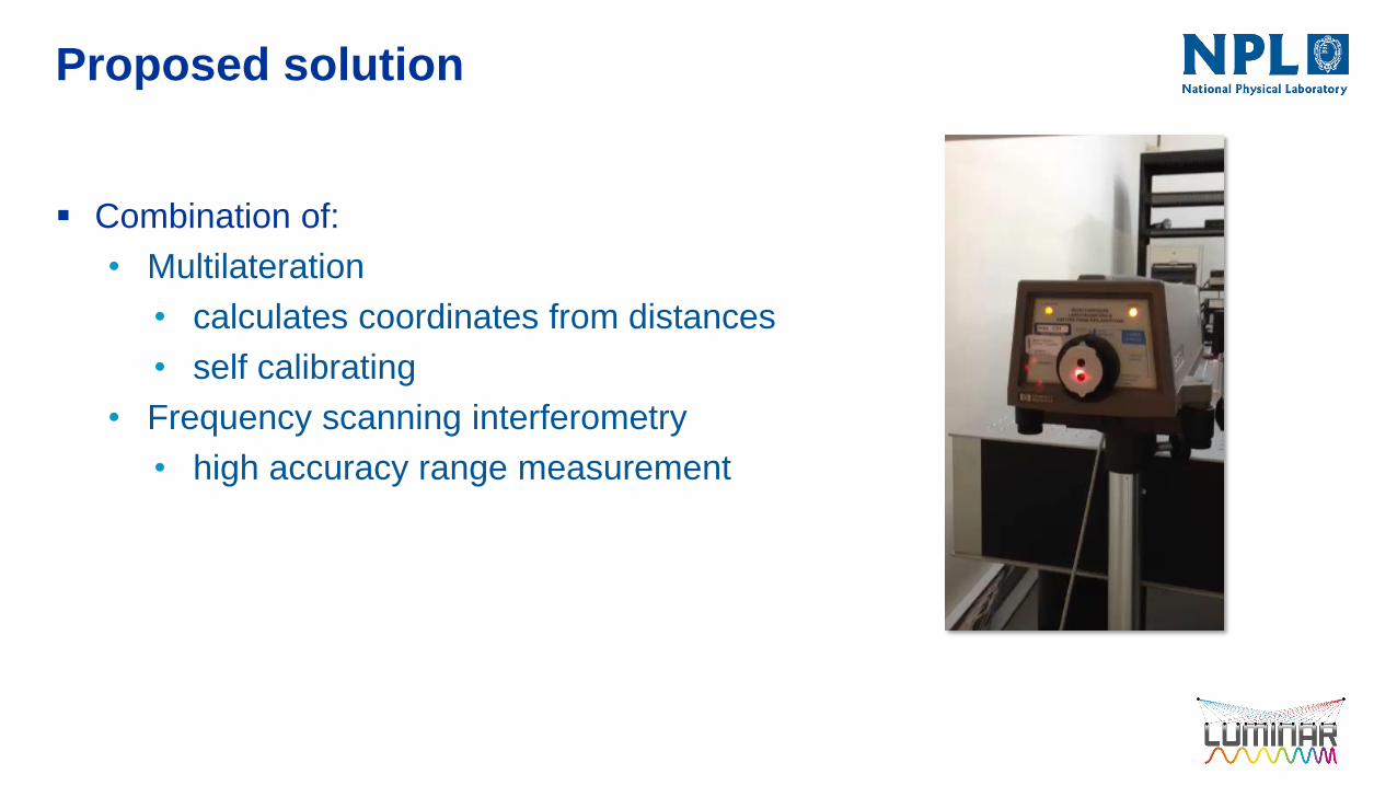
Proposed solution
Combination of:
• Multilateration
• calculates coordinates from distances
• self calibrating
• Frequency scanning interferometry
• high accuracy range measurement
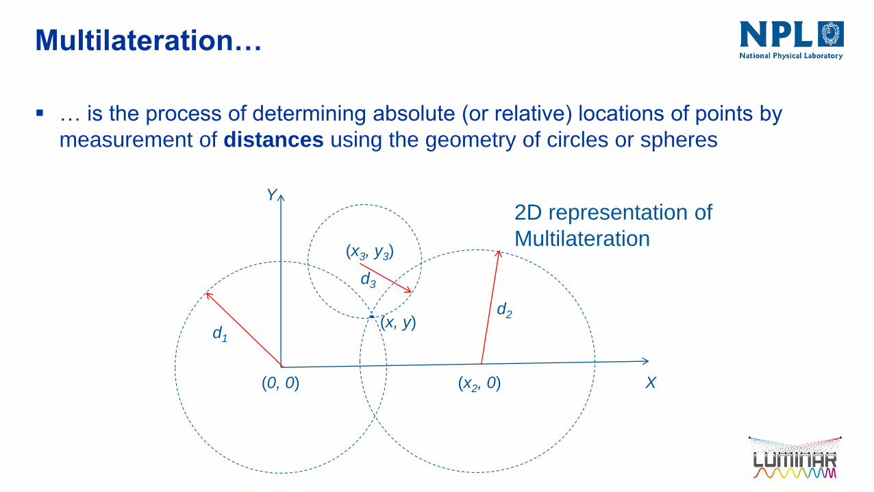
Multilateration…
… is the process of determining absolute (or relative) locations of points by
measurement of distances using the geometry of circles or spheres
Y
X(0, 0)
d1
(x3, y3)
d3
(x2, 0)
d2(x, y)
2D representation of
Multilateration

Multilateration
If instrument locations are known e.g.
• Origin
• Distance x2 along x axis
• On X-Y plane at (x3, y3)
Then measurements d1, d2 and d3 are
sufficient to locate uniquely target
coordinates (x, y)
In 3D and if instrument locations are not
known, we need more information…
(0, 0)
Y
X
d1
(x3, y3)
d3
(x2, 0)
d2(x, y)

Multilateration
Add a fourth instrument at a fourth location, and
Measure ranges to multiple targets
YT1
T3
T2
T4
Z
R2
Rj – jth target coordinates
Ti – ith Instrument coordinates
dij – measured distance from
ith instrument to jth target
d42R1
R3
R4 R5R6
d32
d46
d44
X

Multilateration
Determine coordinates by measuring range, dij from M instrument locations, Ti, to N targets
located at coordinates Rj.
• Self-calibrating if M ≥ 4 and N ≥ 6
• Increasing N, M gives data redundancy -> uncertainty estimates
• Traceable to SI (if dij is traceable)
• Can extend model equation to include other systematic factors – and compensate for
them with full traceability
• Coordinate uncertainty ≈ range uncertainty
Instrument
location
Ti
Target
Rj dij
dRT ijji
(i = 1, …, M)
(j = 1, …, N)
M number of instruments
N number of targets
10

Multilateration
XT1
T3
T2
T4
Y
R2
d42R1
R3
R4 R5R6
d32
d46d44Z
Determine coordinates by measuring range, dij from M
instrument locations, Ti, to N targets located at
coordinates Rj.
• Self-calibrating if M ≥ 4 and N ≥ 6
• Increasing N, M gives data redundancy ->
uncertainty estimates
• Traceable to SI (if dij is traceable)
• Can extend model equation to include other
systematic factors – and compensate for
them with full traceability
• Can achieve coordinate uncertainty ≈ range
uncertainty
How do we determine absolute distance to
multiple targets simultaneously?

Frequency Scanning Interferometry
Developed extensively at Oxford University
• ATLAS
• Oxford/NPL/Etalon presented recent developments at LVMC 2012
Similar to laser radar technology
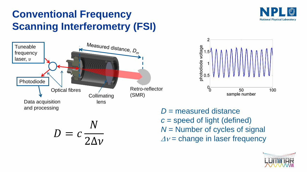
Conventional Frequency
Scanning Interferometry (FSI)
13
D = measured distance
c = speed of light (defined)
N = Number of cycles of signal
Dn = change in laser frequency𝐷 = 𝑐
𝑁
2Δ𝜈
Photodiode
Retro-reflector
(SMR)
Data acquisition
and processing
Collimating
lens
Optical fibres
Tuneable
frequency
laser, 𝜐
Spatial Light Modulator
+ Optics + Camera
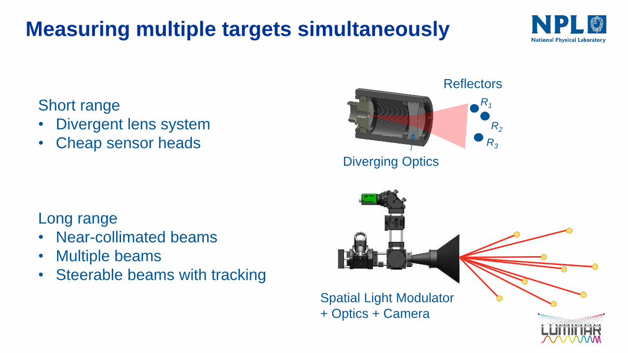
Measuring multiple targets simultaneously
Short range
• Divergent lens system
• Cheap sensor heads
Long range
• Near-collimated beams
• Multiple beams
• Steerable beams with tracking
Reflectors
Diverging Optics
R3
R2
R1

Measuring multiple targets simultaneously
Key component is the SLM
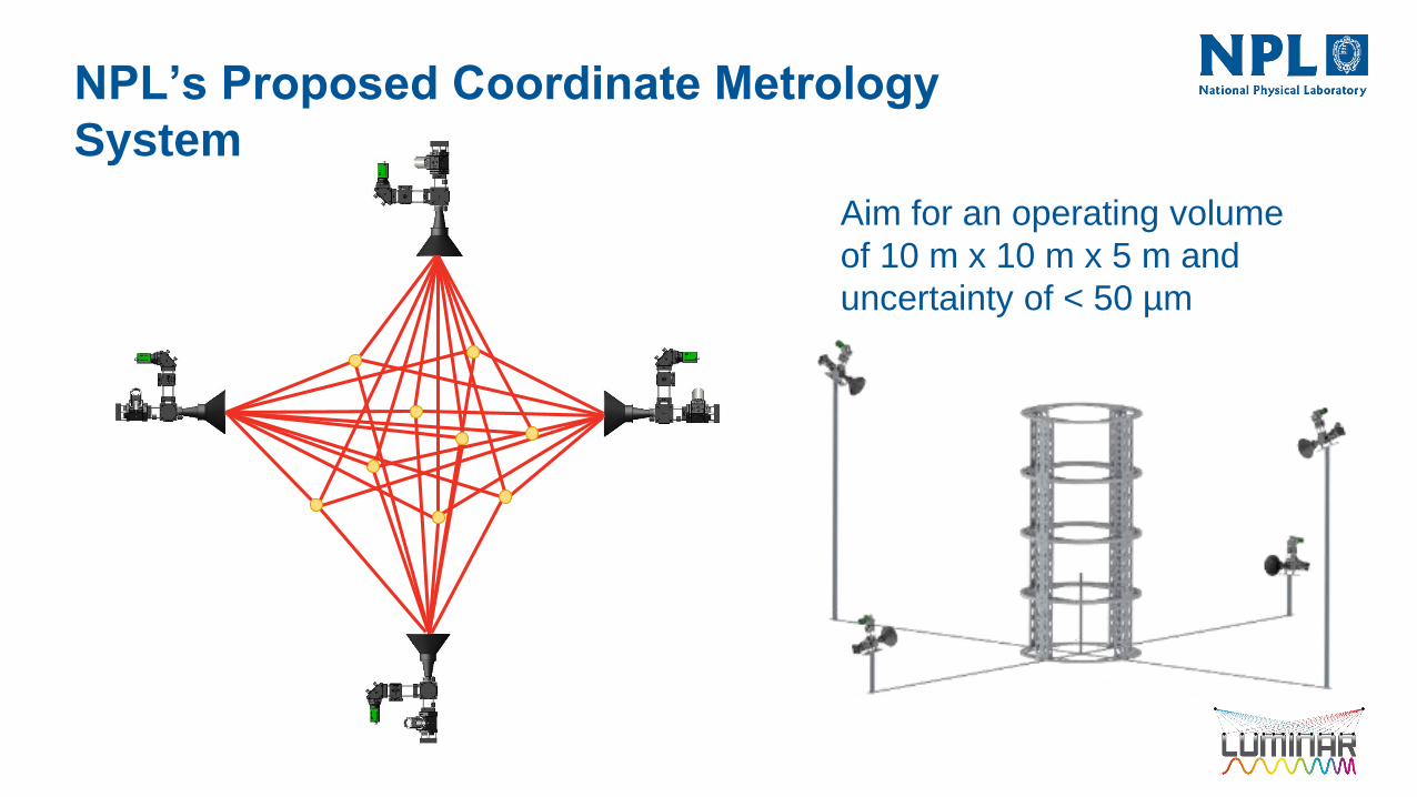
Aim for an operating volume
of 10 m x 10 m x 5 m and
uncertainty of < 50 µm
NPL’s Proposed Coordinate Metrology
System

-6
-4
-2
0
2
4
6
0 0.5 1 1.5 2 2.5 3
Sig
na
l A
mp
litu
de
/ V
Laser Frequency / a.u
-2.5
-2
-1.5
-1
-0.5
0
0.5
1
1.5
2
2.5
0 0.5 1 1.5 2 2.5 3
Sig
na
l A
mp
litu
de
/ V
Laser Frequency / a.u
Extracting signals from multiple targets
Each target shows up as a separate
peak in the frequency domain
Fourier
transform
𝐷 = 𝑐𝑁
2Δ𝜈𝐷 = ? ?𝐷𝑗 = 𝑐
𝑓𝑗
2 𝑑𝜐 𝑑𝑡

Traceability to SI:
Gas Cell Frequency Reference
18
Gas cell provides traceability to the second
and to the metre via the defined speed of
light, c. Uncertainty of ~ 1 ppm
Variable Frequency
Laser, n
Photodiode
Gas Cell Photodiode
Absorption peaks have
known and constant frequencies
Fourier
transform
HCN gas cell
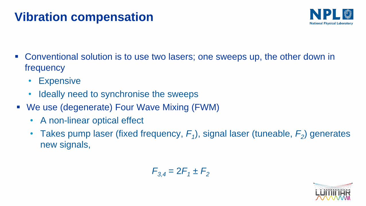
Vibration compensation
Conventional solution is to use two lasers; one sweeps up, the other down in
frequency
• Expensive
• Ideally need to synchronise the sweeps
We use (degenerate) Four Wave Mixing (FWM)
• A non-linear optical effect
• Takes pump laser (fixed frequency, F1), signal laser (tuneable, F2) generates
new signals,
F3,4 = 2F1 ± F2

• Fixed frequency DFB laser – 1564.3 nm
• Original laser - 1530 → 1560 nm
• FWM generated - 1565 → 1600 nm
• Filter out unwanted fixed frequency wavelength
20
Vibration Compensation

• Piezoelectric actuator
• 2 Hz frequency
• 0.1 mm amplitude
• Individual sweep amplitudes: 1.3 mm
• Combined sweep amplitude: 0.1 mm
Vibration / Motion Compensation
Target moving at 100 mm/s
Outline
Introduction
NPL’s Proposed Coordinate Metrology System
Results
Summary & Conclusions
Future Work
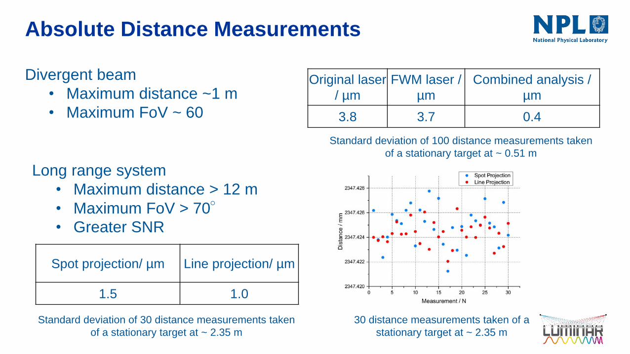
Absolute Distance Measurements
Standard deviation of 100 distance measurements taken
of a stationary target at ~ 0.51 m
Original laser
/ µm
FWM laser /
µm
Combined analysis /
µm
3.8 3.7 0.4
Divergent beam
• Maximum distance ~1 m
• Maximum FoV ~ 60
Spot projection/ µm Line projection/ µm
1.5 1.0
Long range system
• Maximum distance > 12 m
• Maximum FoV > 70°• Greater SNR
Standard deviation of 30 distance measurements taken
of a stationary target at ~ 2.35 m
30 distance measurements taken of a
stationary target at ~ 2.35 m
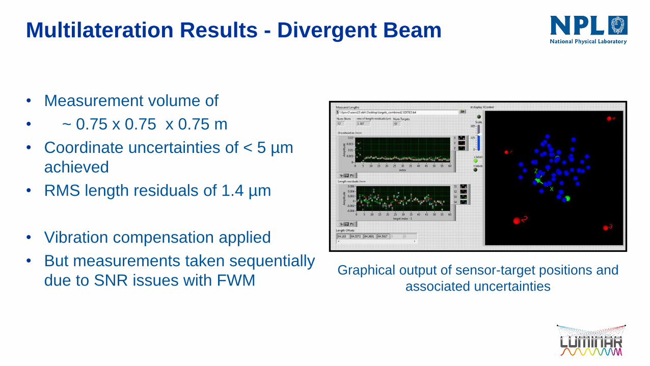
Multilateration Results - Divergent Beam
• Measurement volume of
• ~ 0.75 x 0.75 x 0.75 m
• Coordinate uncertainties of < 5 µm
achieved
• RMS length residuals of 1.4 µm
• Vibration compensation applied
• But measurements taken sequentially
due to SNR issues with FWMGraphical output of sensor-target positions and
associated uncertainties

Multilateration Results - Long Range
Airbus
• 5 x 5 x 3 m measurement volume
• Uncertainties of ~100 µm
• Difference from laser tracker for 2.3 m
artefact of ~90 µm
• Targets measured sequentially
• No vibration compensation
Test setup at Airbus with 4 sensor heads and
12 targets

Multilateration Results – Long RangePTB - Decommissioned Nuclear Reactor
• Max distance = 8.328 m
• Min distance = 3.240 m
• Angular FoV = 70°
• 10 x 5 x 2.5 m measurement volume
• 4 sensor heads, 15 targets
• Targets measured simultaneously
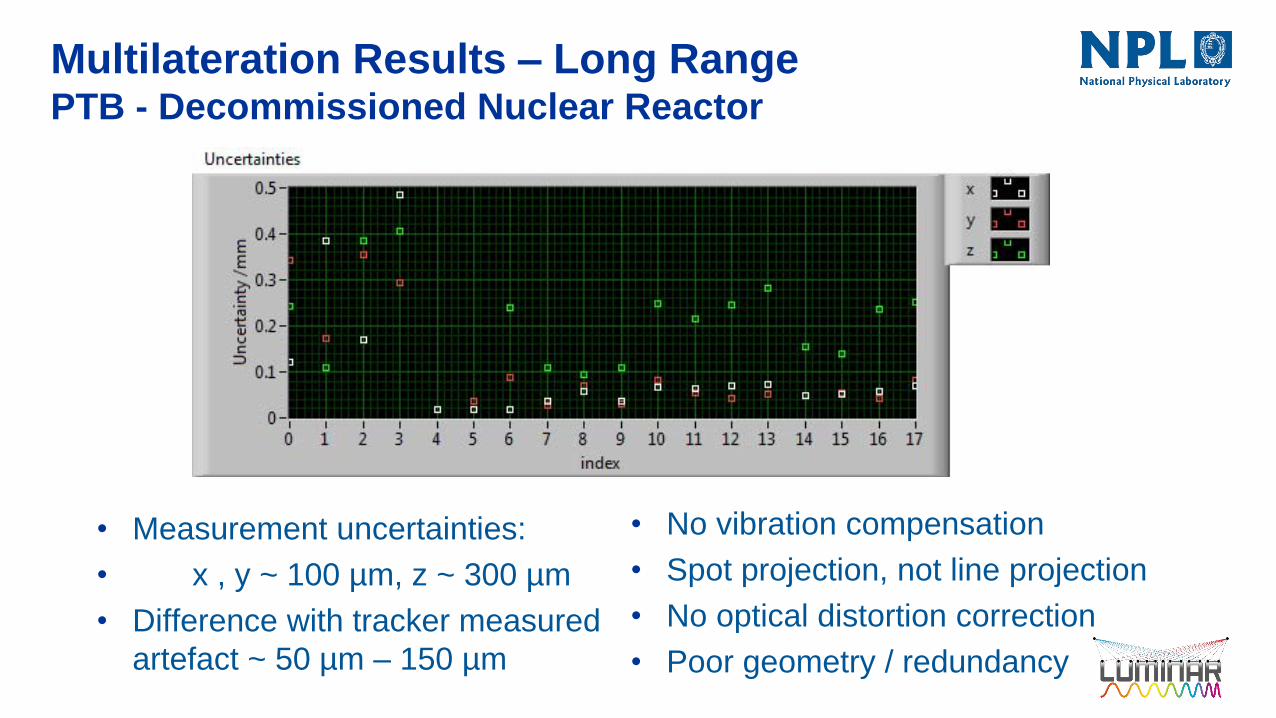
• Measurement uncertainties:
• x , y ~ 100 µm, z ~ 300 µm
• Difference with tracker measured
artefact ~ 50 µm – 150 µm
Multilateration Results – Long RangePTB - Decommissioned Nuclear Reactor
• No vibration compensation
• Spot projection, not line projection
• No optical distortion correction
• Poor geometry / redundancy

Outline
Introduction
NPL’s Proposed Coordinate Metrology System
Results
Summary & Conclusions
Future Work
Summary and Conclusion Prototype proof-of-concept system constructed
Two types of sensor developed
• Short range (simple diverging lens)L
• Long range ( SLM + optics + camera)
Repeatability < 0.5 µm for short range system
Multi-beam steering over wide angular range using SLM
FWM for synchronised dual laser sweep generation – vibration/motion compensation
Simultaneous FSI to multiple targets over large volume from multiple sensors demonstrated
Traceability through direct, in-situ calibration against a gas absorption cell with an uncertainty of
1 ppm.
Multilateration determines un-known system parameter, currently sensor locations and offsets as
well as target coordinates
Currently achieving uncertainties ~ 100 µm (but lots of improvements coming)
Three patents pending

Outline
Introduction
NPL’s Proposed Coordinate Metrology System
Results
Summary & Conclusions
Future Work

Future WorkLots to do!
Improve mechanical stability of sensors
Fix FWM – vibration/motion compensation
Improve optics for long-range sensor
Software improvements/integration
Implement optics calibration in multilateration solution – improve accuracy
Develop (much) faster data acquisition system – increase measurement speed,
implement target tracking
…..

Thank you
32