free float drain trap jah5ra-r jah7ra-r - tlv
TRANSCRIPT

172-65606A-02 (JAH5RA-R/JAH7RA-R) 12 January 2021
Manufacturer
881 Nagasuna, Noguchi, Kakogawa, Hyogo, 675-8511 Japan
Tel: [81]-(0)79-422-1122 Fax: [81]-(0)79-422-0112
Copyright © 2021 by TLV CO., LTD. All rights reserved
Free Float Drain Trap
JAH5RA-R
JAH7RA-R
Introduction Thank you for purchasing the TLV free float drain trap.
This product has been thoroughly inspected before being shipped from the factory. When the product is delivered, before doing anything else, check the specifications and external appearance to make sure nothing is out of the ordinary. Also be sure to read this manual carefully before use and follow the instructions to be sure of using the product properly.
This product is designed, manufactured, and inspected for use with air, inert
gases and condensate. Do not use for toxic, flammable or otherwise
hazardous fluids. Hereafter in this manual, the words “gas” and “gases”
should be read as “inert gas” and “inert gases”.
This free float drain trap employs a precision-ground float and three-point seat. With no hinges or levers, the trap automatically and continuously discharges condensate as it forms in the air/gas system, preventing it from backing up in the system. The three-point seat supports the precision-ground float at three points, ensuring an air-tight seal even under extremely low condensate loads. This free float drain trap is also inline repairable, facilitating repair and maintenance, resulting in considerable time savings.
If detailed instructions for special order specifications or options not contained in this manual are required, please contact TLV for full details.
This instruction manual is intended for use with the model(s) listed on the front cover. It is necessary not only for installation but for subsequent maintenance, disassembly/reassembly and troubleshooting. Please keep it in a safe place for future reference.

172-65606A-02 (JAH5RA-R/JAH7RA-R) 12 Jan 2021
1
Contents
Safety Considerations .......................................................... 1
Checking the Piping ............................................................. 3
Operation ............................................................................. 4
Specifications ....................................................................... 4
Configuration ........................................................................ 5
Installation ............................................................................ 6
The Need for a Pressure-balancing Line ............................. 7
Maintenance ......................................................................... 8
Disassembly/Reassembly .................................................... 9
Instructions for Plug/Holder Disassembly and Reassembly ........ 10
Troubleshooting ................................................................. 12
TLV EXPRESS LIMITED WARRANTY .............................. 13
Options ............................................................................... 15
Safety Considerations Read this section carefully before use and be sure to follow the instructions.
Installation, inspection, maintenance, repairs, disassembly, adjustment and valve
opening/closing should be carried out only by trained maintenance personnel.
The precautions listed in this manual are designed to ensure safety and prevent
equipment damage and personal injury. For situations that may occur as a result
of erroneous handling, three different types of cautionary items are used to
indicate the degree of urgency and the scale of potential damage and danger:
DANGER, WARNING and CAUTION.
The three types of cautionary items above are very important for safety: be sure to
observe all of them as they relate to installation, use, maintenance, and repair.
Furthermore, TLV accepts no responsibility for any accidents or damage occurring
as a result of failure to observe these precautions.
Symbols
Indicates a DANGER, WARNING or CAUTION item.
DANGER
Indicates an urgent situation which poses a threat of death or serious injury
WARNING
Indicates that there is a potential threat of death or serious injury
CAUTION
Indicates that there is a possibility of injury or equipment/product damage

172-65606A-02 (JAH5RA-R/JAH7RA-R) 12 Jan 2021
2
WARNING DO NOT use for toxic, flammable or otherwise hazardous
fluids. This product is a drain trap that discharges condensate from air or inert gas systems. Use only for air or inert gas. This product is for intended use only. Improper use may result in such hazards as damage to the product or malfunctions that may lead to serious accidents.
NEVER apply direct heat to the float. The float may explode due to increased internal pressure, causing accidents leading to serious injury or damage to property and equipment.
CAUTION
Install properly and DO NOT use this product outside the
recommended operating pressure, temperature and other
specification ranges. Improper use may result in such hazards as damage to the product or malfunctions that may lead to serious accidents. Local regulations may restrict the use of this product to below the conditions quoted.
DO NOT use this product in excess of the maximum operating
pressure differential. Such use could make discharge impossible (blocked).
Use hoisting equipment for heavy objects (weighing
approximately 20 kg (44 lb) or more). Failure to do so may result in back strain or other injury if the object should fall.
Take measures to prevent people from coming into direct
contact with product outlets. Failure to do so may result in burns or other injury from the discharge of fluids.
When disassembling or removing the product, wait until the
internal pressure equals atmospheric pressure and the surface
of the product has cooled to room temperature. Disassembling or removing the product when it is hot or under pressure may lead to discharge of fluids, causing burns, other injuries or damage.
Be sure to use only the recommended components when
repairing the product, and NEVER attempt to modify the
product in any way. Failure to observe these precautions may result in damage to the product and burns or other injury due to malfunction or the discharge of fluids.
Use only under conditions in which no freeze-up will occur. Freezing may damage the product, leading to fluid discharge, which may cause burns or other injury.
Use only under conditions in which no water hammer will occur. The impact of water hammer may damage the product, leading to fluid discharge, which may cause burns or other injury.

172-65606A-02 (JAH5RA-R/JAH7RA-R) 12 Jan 2021
3
Checking the Piping
DO NOT use for toxic, flammable or otherwise hazardous fluids. This
product is a drain trap that discharges condensate from air or inert gas
systems. Use only for air or inert gas. This product is for intended use
only. Improper use may result in such hazardous as damage to the
product or malfunctions that may lead to serious accidents.
WARNING
Use only under conditions in which no water hammer will occur. The impact of water hammer may damage the product, leading to fluid discharge, which may cause burns or other injury.
CAUTION
Check to make sure that the pipes to be connected to the trap have been installed properly.
1. Is the pipe diameter suitable? 2. Is the piping where the trap is to be installed horizontal? 3. Has sufficient space been secured for maintenance? 4. Have isolation valves been installed at the inlet and outlet? If the outlet is subject
to back pressure, has a check valve been installed? 5. Is the inlet pipe as short as possible, with as few bends as possible, and installed
so the liquid will flow naturally down into the trap? 6. Has the piping work been done correctly, as shown in the figures below?
Requirement Correct Incorrect
Install catchpot with the
proper diameter.
Diameter is too small.
Make sure the flow of
condensate is not
obstructed.
Diameter is too small and inlet protrudes into pipe interior.
To prevent rust and scale from flowing into the trap, the inlet pipe should be connected 25 – 50 mm (1 – 2 in) above the base of the T-pipe.
Rust and scale flow into the trap with the condensate.
When installing on the blind
end, make sure the flow of
condensate is not
obstructed.
Condensate collects in the pipe.

172-65606A-02 (JAH5RA-R/JAH7RA-R) 12 Jan 2021
4
Operation Principles of condensate discharge:
1. Start-up At start-up, the float is sealing the valve seat. NOTE: If there is no condensate in the trap body,
prime with some water through the pressure- balancing line before startup.(Do this after installation and disassembly/ inspection)
Pressure-balancing Line
Valve Seat
2. Condensate Discharge As air/gas is supplied, condensate flow begins. The rising condensate level causes the float to rise due to buoyancy, opening the valve seat and allowing condensate to be discharged.
3. Closed Position When the condensate flow rate decreases, the float falls, closing off the valve seat opening. A water seal is maintained at all times over the valve seat to prevent air/gas leakage.
Air/Gas Condensate
Specifications
Install properly and DO NOT use this product outside the recommended operating pressure, temperature and other specification ranges. Improper use may result in such hazards as damage to the product or malfunctions which may lead to serious accidents. Local regulations may restrict the use of this product to below the conditions quoted.
CAUTION
DO NOT use this product in excess of the maximum operating pressure differential; such use could make discharge impossible (blocked). CAUTION
Use only under conditions in which no freeze-up will occur. Freezing may damage the product, leading to fluid discharge, which may cause burns or other injury.
CAUTION
Refer to the product nameplate for detailed specifications.
JAH5RA-R Model
Maximum AllowableTemperature (TMA)*
Maximum AllowablePressure*
Nominal Diameter
Maximum DifferentialPressure
Production Lot No.
Valve No.**
Maximum OperatingTemperature
JAH7RA-R Model
Maximum AllowableTemperature (TMA)*
Maximum AllowablePressure*
Maximum OperatingTemperature
Nominal Diameter
Maximum DifferentialPressureValve No.**
Production Lot No.
* Maximum allowable pressure (PMA) and maximum allowable temperature (TMA) are PRESSURE SHELL DESIGN CONDITIONS, NOT OPERATING CONDITIONS.
** Valve No. is displayed for products with options. This item is omitted from the nameplate when there are no options.
172-65606A-02 (JAH5RA-R/JAH7RA-R) 12 Jan 2021
5
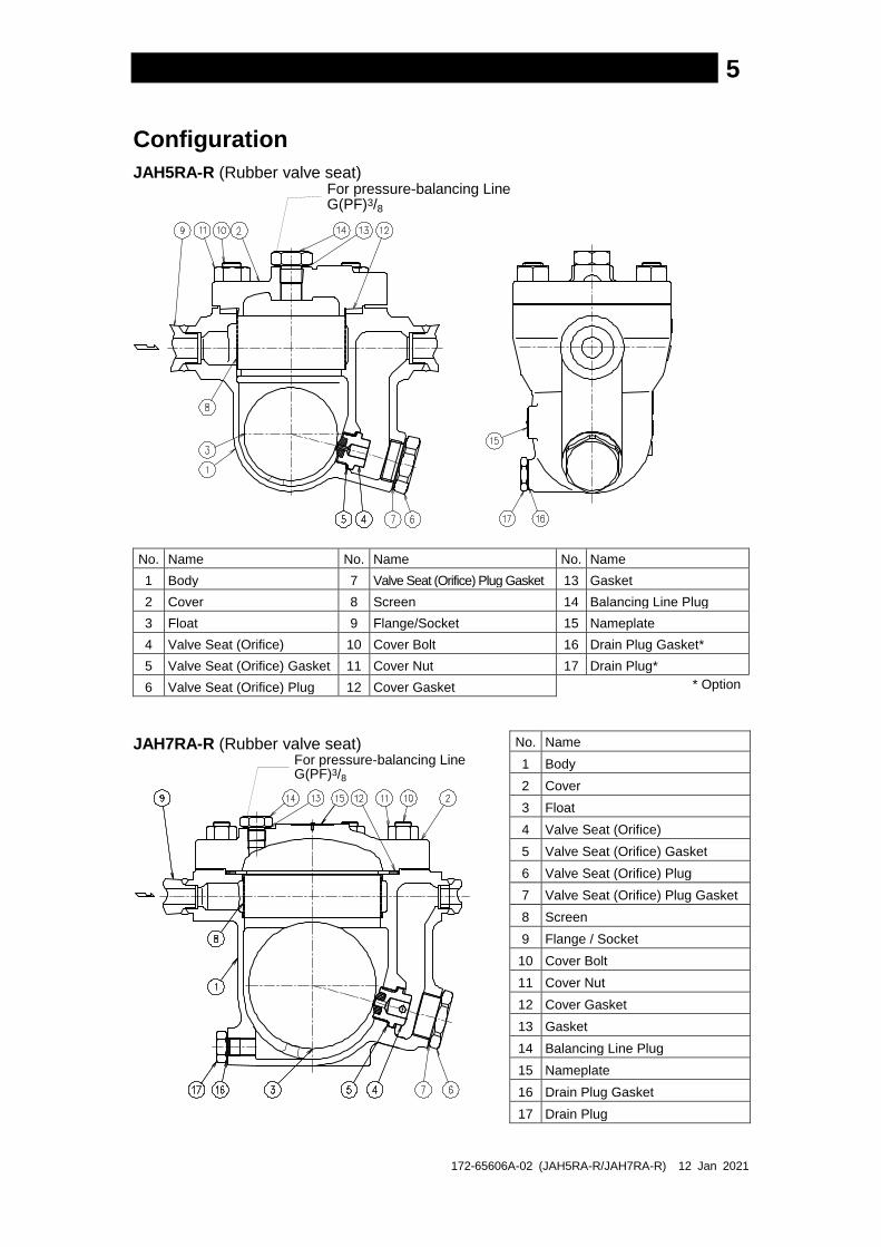
Configuration
JAH5RA-R (Rubber valve seat) For pressure-balancing LineG(PF)3/8
No. Name No. Name No. Name
1 Body 7 Valve Seat (Orifice) Plug Gasket 13 Gasket
2 Cover 8 Screen 14 Balancing Line Plug
3 Float 9 Flange/Socket 15 Nameplate
4 Valve Seat (Orifice) 10 Cover Bolt 16 Drain Plug Gasket*
5 Valve Seat (Orifice) Gasket 11 Cover Nut 17 Drain Plug*
6 Valve Seat (Orifice) Plug 12 Cover Gasket * Option
JAH7RA-R (Rubber valve seat) For pressure-balancing LineG(PF)3/8
No. Name
1 Body
2 Cover
3 Float
4 Valve Seat (Orifice)
5 Valve Seat (Orifice) Gasket
6 Valve Seat (Orifice) Plug
7 Valve Seat (Orifice) Plug Gasket
8 Screen
9 Flange / Socket
10 Cover Bolt
11 Cover Nut
12 Cover Gasket
13 Gasket
14 Balancing Line Plug
15 Nameplate
16 Drain Plug Gasket
17 Drain Plug
172-65606A-02 (JAH5RA-R/JAH7RA-R) 12 Jan 2021
6
Installation
DO NOT use for toxic, flammable or otherwise hazardous fluids. This
product is a drain trap that discharges condensate from air or inert gas
systems. Use only for air or inert gas. This product is for intended use
only. Improper use may result in such hazardous as damage to the
product or malfunctions that may lead to serious accidents.
WARNING
Install properly and DO NOT use this product outside the recommended operating pressure, temperature and other specification ranges. Improper use may result in such hazards as damage to the product or malfunctions which may lead to serious accidents. Local regulations may restrict the use of this product to below the conditions quoted.
CAUTION
Use hoisting equipment for heavy objects (weighing approximately 20 kg (44 lb) or more). Failure to do so may result in back strain or other injury if the object should fall.
CAUTION
Take measures to prevent people from coming into direct contact with
product outlets. Failure to do so may result in burns or other injury from
the discharge of fluids. CAUTION
Installation, inspection, maintenance, repairs, disassembly, adjustment and valve
opening/closing should be carried out only by trained maintenance personnel.
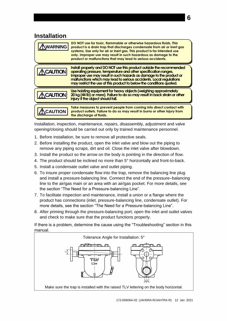
1. Before installation, be sure to remove all protective seals.
2. Before installing the product, open the inlet valve and blow out the piping to
remove any piping scraps, dirt and oil. Close the inlet valve after blowdown.
3. Install the product so the arrow on the body is pointing in the direction of flow.
4. The product should be inclined no more than 5° horizontally and front-to-back.
5. Install a condensate outlet valve and outlet piping.
6. To insure proper condensate flow into the trap, remove the balancing line plug
and install a pressure-balancing line. Connect the end of the pressure–balancing
line to the air/gas main or an area with an air/gas pocket. For more details, see
the section “The Need for a Pressure-balancing Line”.
7. To facilitate inspection and maintenance, install a union or a flange where the
product has connections (inlet, pressure-balancing line, condensate outlet). For
more details, see the section “The Need for a Pressure-balancing Line”.
8. After priming through the pressure-balancing port, open the inlet and outlet valves
and check to make sure that the product functions properly.
If there is a problem, determine the cause using the “Troubleshooting” section in this
manual.
Tolerance Angle for Installation: 5°
Make sure the trap is installed with the raised TLV lettering on the body horizontal.

172-65606A-02 (JAH5RA-R/JAH7RA-R) 12 Jan 2021
7
The Need for a Pressure-balancing Line
This drain trap is designed to automatically discharge inflowing condensate. However, if the condensate completely fills the inlet path of the trap, air or gas in the trap body will not be able to escape, preventing displacement by condensate, and thus preventing condensate from entering the trap. This phenomena is called air binding. Air binding occurs more often in piping with long horizontal lengths, smaller diameters or multiple bends. To prevent air binding and ensure air or gas can be displaced by incoming condensate, a pressure-balancing line should be installed between the trap cover and the dry portion of the receiver tank.
Connect the pressure-balancing line in the following manner:
Receiver Tank Air/Gas Main
Pressure-balancingLine
172-65606A-02 (JAH5RA-R/JAH7RA-R) 12 Jan 2021
8
Maintenance
Take measures to prevent people from coming into direct contact with product outlets. Failure to do so may result in burns or other injury from the discharge of fluids.
CAUTION
Be sure to use only the recommended components when repairing the product, and NEVER attempt to modify the product in any way. Failure to observe these precautions may result in damage to the product or burns or other injury due to malfunction or the discharge of fluids.
CAUTION
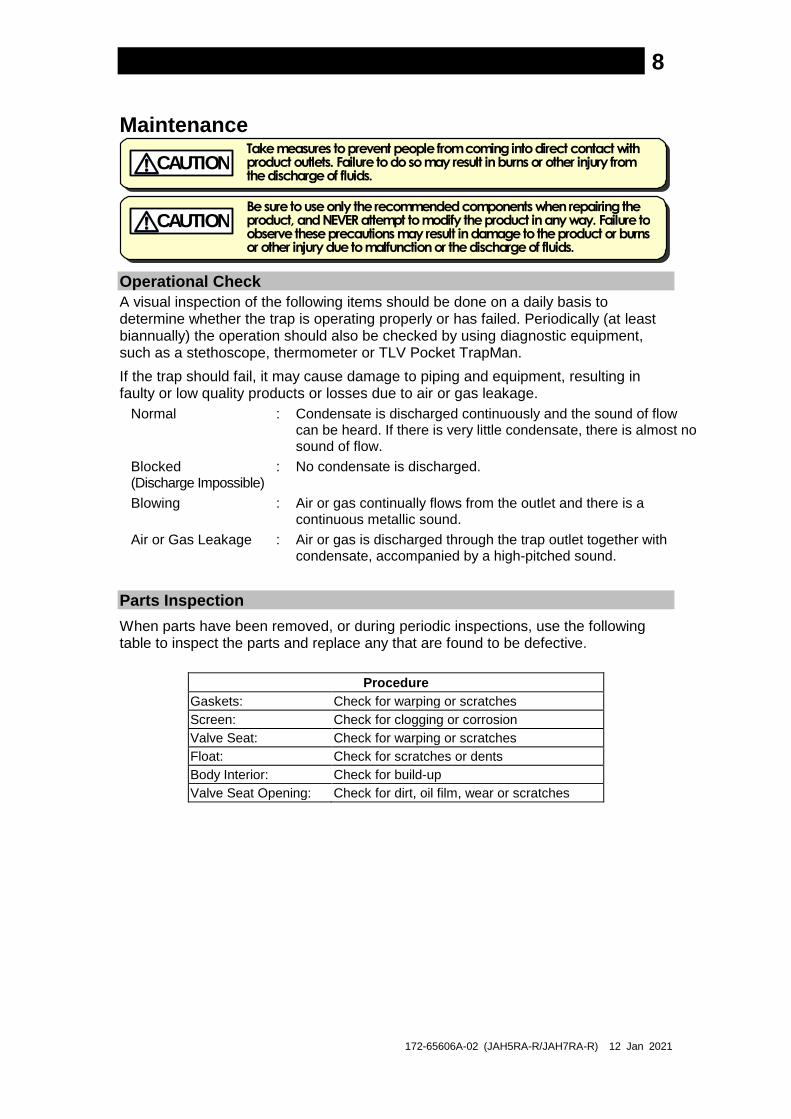
Operational Check
A visual inspection of the following items should be done on a daily basis to determine whether the trap is operating properly or has failed. Periodically (at least biannually) the operation should also be checked by using diagnostic equipment, such as a stethoscope, thermometer or TLV Pocket TrapMan.
If the trap should fail, it may cause damage to piping and equipment, resulting in faulty or low quality products or losses due to air or gas leakage.
Normal : Condensate is discharged continuously and the sound of flow can be heard. If there is very little condensate, there is almost no sound of flow.
Blocked (Discharge Impossible)
: No condensate is discharged.
Blowing : Air or gas continually flows from the outlet and there is a continuous metallic sound.
Air or Gas Leakage : Air or gas is discharged through the trap outlet together with condensate, accompanied by a high-pitched sound.
Parts Inspection
When parts have been removed, or during periodic inspections, use the following table to inspect the parts and replace any that are found to be defective.
Procedure
Gaskets: Check for warping or scratches
Screen: Check for clogging or corrosion
Valve Seat: Check for warping or scratches
Float: Check for scratches or dents
Body Interior: Check for build-up
Valve Seat Opening: Check for dirt, oil film, wear or scratches

172-65606A-02 (JAH5RA-R/JAH7RA-R) 12 Jan 2021
9
Disassembly/Reassembly
NEVER apply direct heat to the float. The float may explode due to increased internal pressure, causing accidents leading to serious injury or damage to property and equipment.
WARNING
Use hoisting equipment for heavy objects (weighing approximately 20 kg (44 lb) or more). Failure to do so may result in back strain or other injury if the object should fall.
CAUTION
When disassembling or removing the product, wait until the internal pressure
equals atmospheric pressure and the surface of the product has cooled to room
temperature. Disassembling or removing the product when it is hot or under
pressure may lead to discharge of fluids, causing burns, other injuries or damage.
CAUTION
Use the following procedures to remove components. Use the same procedures in reverse to reassemble. (Installation, inspection, maintenance, repairs, disassembly, adjustment and valve opening/closing should be carried out only by trained maintenance personnel.)
Drain Plug: JAH7RA-R (Option for JAH5RA-R)
Part During Disassembly During Reassembly
Drain Plug Remove with a socket wrench Consult the table of tightening torques and tighten to the proper torque
Drain Plug Gasket
Remove the gasket and clean sealing surfaces
Replace with a new gasket; coat surfaces with anti-seize
Detaching/Reattaching the Cover and its Components NOTE: Disconnect any lines that must be disconnected before disassembly can take place
(inlet piping, pressure-balancing line, condensate discharge piping, etc.).
Part During Disassembly During Reassembly
Cover Nut Remove with a socket wrench
Consult the table of tightening torques and tighten to the proper torque
Cover Remove by lifting up and off Align the arrows on the body and cover and reattach
Cover Gasket Remove the gasket and clean sealing surfaces on the body and cover
Replace with a new gasket; Make sure there are no pieces of the old gasket left on the sealing surfaces of the body and cover
Balancing Line Plug
Remove with a wrench Consult the table of tightening torques and tighten to the proper torque
Plug Gasket Remove the gasket and clean sealing surfaces
Replace with a new gasket; coat surfaces with anti-seize
Disassembly/Reassembly of Internal Components
Part During Disassembly During Reassembly
Screen Remove by lifting straight up and out while turning
Align the screen/float cover and insert, making sure the top of the screen does not stick up out of the body
Float Remove, being careful not to scratch the polished surface
Insert, being careful not to scratch the polished surface
Orifce Plug Remove with a socket wrench Consult the table of tightening torques and tighten to the proper torque
Valve Seat Plug Gasket
Remove the gasket and clean sealing surfaces
Replace with a new gasket; coat surfaces with anti-seize
Valve Seat Remove with a socket wrench Consult the table of tightening torques and tighten to the proper torque; be careful not to scratch the surface
Valve Seat Gasket
Remove the gasket and clean sealing surfaces
Replace with a new gasket; coat surfaces with anti-seize

172-65606A-02 (JAH5RA-R/JAH7RA-R) 12 Jan 2021
10
Table of Tightening Torques
Part Name
JAH5RA-R JAH7RA-R
Torque Distance Across Flats Torque Distance Across Flats
Nm (lbfft) mm (in) Nm (lbfft) mm (in)
Valve Seat 140 (100) 17 (21/32) 280 (210) 26 (1)
Valve Seat Plug 180 (130) 38 (11/2) 420 (310) 50 (131/32)
Cover Nut 160 (115) 22 (7/8) 200 (150) 24 (15/16)
Balancing Line Plug 100 (73) 26 (1) 100 (73) 26 (1)
Drain Plug 35 (26) 21 (13/16) 100 (73) 26 (1)
(1 Nm 10 kgcm) NOTE: - Coat all threaded portions and valve seat gasket with anti-seize. - Tightening torques for metal and rubber valve seats are identical. - If drawings or other special documentation were supplied for the product, any torque
given there takes precedence over values shown here.
Instructions for Plug/Holder Disassembly and Reassembly The seal on the threaded plugs/holders found on TLV products is formed by a flat metal gasket. There are various installation orientations for the gaskets, such as horizontal, diagonal and downward, and the gasket may be pinched in the thread recesses during assembly.
Instructions for Disassembly and Reassembly
1. Remove the plug/holder using a tool of the specified size (distance across flats).
2. The gasket should not be reused. Be sure to replace it with a new gasket.
3. Clean the gasket surfaces of the plug/holder and the product body using a rag and/or cleaning agents, then check to make sure the surfaces are not scratched or deformed.
4. Coat both the gasket surface of the plug/holder and the threads of the plug/holder with anti-seize, then press the gasket onto the center of the gasket surface of the plug/holder, making sure the anti-seize affixes the gasket tightly to the plug/holder. Check to make sure the gasket is not caught in the recesses of the threads.
5. Hold the plug/holder upside down to make sure that the anti-seize makes the gasket stick to the plug/holder even when the plug/holder is held upside down.
6. Screw the plug/holder by hand into the product body while making sure that the gasket remains tightly affixed to the center of the gasket surface of the plug/holder. Make sure the entire gasket is making contact with the gasket surface of the product body. It is important at this point to make sure the gasket is not pinched in the thread recesses of the plug/holder.
7. Tighten the plug/holder to the proper torque.
8. Next, begin the supply of air/gas and check to make sure there is no leakage from the part just tightened. If there is leakage, immediately close the inlet valve and, if there is a bypass valve, take the necessary steps to release any residual pressure. After the surface of the product cools to room temperature, repeat the procedure beginning from step 1.
Gasket
Do not pinch gasket inthreaded recesses
Coat withanti-seize
Gasket Surface
3.
4.
5.
6.

172-65606A-02 (JAH5RA-R/JAH7RA-R) 12 Jan 2021
11
Exploded View
JAH5RA-R
Cover Gasket
Screen
Float
Cover Bolt
Balancing-line Plug
Balancing-linePlug Gasket
Cover Nut
Cover
Valve Seat
Valve Seat Plug Gasket
Valve Seat Plug
Valve Seat Gasket
Drain Plug Gasket (Option)
Drain Plug (Option)
Nameplate
Body
JAH7RA-R
Screen
Float
Cover Bolt
Body
Valve Seat
Valve Seat Plug Gasket
Valve Seat Plug
Valve Seat Gasket
Drain Plug Gasket
Drain Plug
Balancing-line Plug
Balancing-line Plug Gasket
Cover Nut
Cover
Cover Gasket

172-65606A-02 (JAH5RA-R/JAH7RA-R) 12 Jan 2021
12
Troubleshooting
NEVER apply direct heat to the float. The float may explode due to increased internal pressure, causing accidents leading to serious injury or damage to property and equipment.
WARNING
When disassembling or removing the product, wait until the internal pressure equals atmospheric pressure and the surface of the product has cooled to room temperature. Disassembling or removing the product when it is hot or under pressure may lead to discharge of fluids, causing burns, other injuries or damage.
CAUTION
When the product fails to operate properly, use the following table to locate the cause and remedy.
Problem Cause Remedy
No condensate is discharged (blocked) or discharge is poor
The float is damaged or filled with condensate
Replace with a new float
The valve seat opening, screen or piping are clogged with rust and scale
Clean parts
Air binding has occurred Make sure a pressure-balancing line is installed; if already installed, make sure it has not become dislodged or is not incorrectly installed
The trap operating pressure exceeds the maximum specified pressure, or whether there is insufficient pressure differential between the trap inlet and outlet
Compare specifications and actual operating conditions
The specific gravity of the fluid is not suitable for this product
Consult TLV
Air/gas is discharged or leaks from the outlet (blowing) (air/gas leakage)
Clogged valve seat opening or rust and scale build-up beneath the float
Clean parts
Scratches on the valve seat Replace with a new valve seat
The float is misshapen or has a build-up Clean float or replace with a new float
Improper installation orientation Correct the installation
Trap vibration Lengthen the inlet piping and fasten it securely
There is no condensate in the drain trap body, no water seal around the valve seat
Prime the drain trap
Air/gas is leaking from a place other than the outlet
Gasket deterioration or damage Replace with new gasket(s)
Improper tightening torques were used Tighten to the proper torque
Float frequently becomes damaged
Water hammer has occurred Study and correct the piping
172-65606A-02 (JAH5RA-R/JAH7RA-R) 12 Jan 2021
13
TLV EXPRESS LIMITED WARRANTY Subject to the limitations set forth below, TLV Corporation, a North Carolina corporation
(“TLV”) warrants that products which are sold by it, TLV CO., LTD., a Japanese
corporation (“TLVJ”) or TLV International, Inc., a Japanese corporation (“TII”), (hereinafter
the “Products”) are designed and manufactured by TLVJ, conform to the specifications
published by TLV for the corresponding part numbers (the “Specifications”) and are free
from defective workmanship and materials. With regard to products or components
manufactured by unrelated third parties (the “Components”), TLV provides no warranty
other than the warranty from the third party manufacturer(s), if any.
Exceptions to Warranty
This warranty does not cover defects or failures caused by:
1. improper shipping, installation, use, handling, etc., by other than TLV or service
representatives authorized by TLV; or
2. dirt, scale or rust, etc.; or
3. improper disassembly and reassembly, or inadequate inspection and
maintenance by other than TLV or service representatives authorized by TLV; or
4. disasters or forces of nature or Acts of God; or
5. abuse, abnormal use, accidents or any other cause beyond the control of TLV; or
6. improper storage, maintenance or repair; or
7. operation of the Products not in accordance with instructions issued with the
Products or with accepted industry practices; or
8. use for a purpose or in a manner for which the Products were not intended; or
9. use of the Products in a manner inconsistent with the Specifications; or
10. use of the Products with Hazardous Fluids (fluids other than steam, air, water,
nitrogen, carbon dioxide and inert gases (helium, neon, argon, krypton, xenon
and radon)); or
11. failure to follow the instructions contained in the TLV Instruction Manual for the
Product.
Duration of Warranty
This warranty is effective for a period of the earlier of: (i) three (3) years after delivery
of Products to the first end user in the case of sealed SST-Series Products for use in
steam pressure service up to 650 psig; (ii) two (2) years after delivery of Products to
the first end user in the case of PowerTrap® units; or (iii) one (1) year after delivery of
Products to the first end user in the case of all other Products. Notwithstanding the
foregoing, asserting a claim under this warranty must be brought by the earlier of one
of the foregoing periods, as applicable, or within five (5) years after the date of delivery
to the initial buyer if not sold initially to the first end user.
ANY IMPLIED WARRANTIES NOT NEGATED HEREBY WHICH MAY ARISE BY OPERATION
OF LAW, INCLUDING THE IMPLIED WARRANTIES OF MERCHANTABILITY AND FITNESS
FOR A PARTICULAR PURPOSE AND ANY EXPRESS WARRANTIES NOT NEGATED
HEREBY, ARE GIVEN SOLELY TO THE INITIAL BUYER AND ARE LIMITED IN DURATION
TO ONE (1) YEAR FROM THE DATE OF SHIPMENT BY TLV.
Exclusive Remedy
THE EXCLUSIVE REMEDY UNDER THIS WARRANTY, UNDER ANY EXPRESS WARRANTY
OR UNDER ANY IMPLIED WARRANTIES NOT NEGATED HEREBY (INCLUDING THE
IMPLIED WARRANTIES OF MERCHANTABILITY AND FITNESS FOR A PARTICULAR
PURPOSE), IS REPLACEMENT; PROVIDED: (a) THE CLAIMED DEFECT IS REPORTED TO
TLV IN WRITING WITHIN THE APPLICABLE WARRANTY PERIOD, INCLUDING A

172-65606A-02 (JAH5RA-R/JAH7RA-R) 12 Jan 2021
14
DETAILED WRITTEN DESCRIPTION OF THE CLAIMED DEFECT AND HOW AND WHEN
THE CLAIMED DEFECTIVE PRODUCT WAS USED; AND (b) THE CLAIMED DEFECTIVE
PRODUCT AND A COPY OF THE PURCHASE INVOICE IS RETURNED TO TLV, FREIGHT
AND TRANSPORTATION COSTS PREPAID, UNDER A RETURN MATERIAL
AUTHORIZATION AND TRACKING NUMBER ISSUED BY TLV. ALL LABOR COSTS,
SHIPPING COSTS, AND TRANSPORTATION COSTS ASSOCIATED WITH THE RETURN
OR REPLACEMENT OF THE CLAIMED DEFECTIVE PRODUCT ARE SOLELY THE
RESPONSIBILITY OF BUYER OR THE FIRST END USER. TLV RESERVES THE RIGHT TO
INSPECT ON THE FIRST END USER’S SITE ANY PRODUCTS CLAIMED TO BE DEFECTIVE
BEFORE ISSUING A RETURN MATERIAL AUTHORIZATION. SHOULD SUCH INSPECTION
REVEAL, IN TLV’S REASONABLE DISCRETION, THAT THE CLAIMED DEFECT IS NOT
COVERED BY THIS WARRANTY, THE PARTY ASSERTING THIS WARRANTY SHALL PAY
TLV FOR THE TIME AND EXPENSES RELATED TO SUCH ON-SITE INSPECTION.
Exclusion of Consequential and Incidental Damages
IT IS SPECIFICALLY ACKNOWLEDGED THAT THIS WARRANTY, ANY OTHER EXPRESS
WARRANTY NOT NEGATED HEREBY, AND ANY IMPLIED WARRANTY NOT NEGATED
HEREBY, INCLUDING THE IMPLIED WARRANTIES OF MERCHANTABILITY AND FITNESS
FOR A PARTICULAR PURPOSE, DO NOT COVER, AND NEITHER TLV, TII NOR TLVJ WILL
IN ANY EVENT BE LIABLE FOR, INCIDENTAL OR CONSEQUENTIAL DAMAGES,
INCLUDING, BUT NOT LIMITED TO LOST PROFITS, THE COST OF DISASSEMBLY AND
SHIPMENT OF THE DEFECTIVE PRODUCT, INJURY TO OTHER PROPERTY, DAMAGE TO
BUYER’S OR THE FIRST END USER’S PRODUCT, DAMAGE TO BUYER’S OR THE FIRST
END USER’S PROCESSES, LOSS OF USE, OR OTHER COMMERCIAL LOSSES. WHERE,
DUE TO OPERATION OF LAW, CONSEQUENTIAL AND INCIDENTAL DAMAGES UNDER
THIS WARRANTY, UNDER ANY OTHER EXPRESS WARRANTY NOT NEGATED HEREBY
OR UNDER ANY IMPLIED WARRANTY NOT NEGATED HEREBY (INCLUDING THE IMPLIED
WARRANTIES OF MERCHANTABILITY AND FITNESS FOR A PARTICULAR PURPOSE)
CANNOT BE EXCLUDED, SUCH DAMAGES ARE EXPRESSLY LIMITED IN AMOUNT TO
THE PURCHASE PRICE OF THE DEFECTIVE PRODUCT. THIS EXCLUSION OF
CONSEQUENTIAL AND INCIDENTAL DAMAGES, AND THE PROVISION OF THIS
WARRANTY LIMITING REMEDIES HEREUNDER TO REPLACEMENT, ARE INDEPENDENT
PROVISIONS, AND ANY DETERMINATION THAT THE LIMITATION OF REMEDIES FAILS OF
ITS ESSENTIAL PURPOSE OR ANY OTHER DETERMINATION THAT EITHER OF THE
ABOVE REMEDIES IS UNENFORCEABLE, SHALL NOT BE CONSTRUED TO MAKE THE
OTHER PROVISIONS UNENFORCEABLE.
Exclusion of Other Warranties
THIS WARRANTY IS IN LIEU OF ALL OTHER WARRANTIES, EXPRESS OR IMPLIED,
AND ALL OTHER WARRANTIES, INCLUDING BUT NOT LIMITED TO THE IMPLIED
WARRANTIES OF MERCHANTABILITY AND FITNESS FOR A PARTICULAR PURPOSE,
ARE EXPRESSLY DISCLAIMED.
Severability
Any provision of this warranty which is invalid, prohibited or unenforceable in any
jurisdiction shall, as to such jurisdiction, be ineffective to the extent of such invalidity,
prohibition or unenforceability without invalidating the remaining provisions hereof,
and any such invalidity, prohibition or unenforceability in any such jurisdiction shall
not invalidate or render unenforceable such provision in any other jurisdiction.
13901 South Lakes Drive, Charlotte, NC 28273-6790, U.S.A.
Tel: [1]-704-597-9070 Fax: [1]-704-583-1610

172-65606A-02 (JAH5RA-R/JAH7RA-R) 12 Jan 2021
15
Options
The options shown below are
available for this product on
request. Please compare with
the product you received.
JAH5RA-R JAH7RA-R
Options for Area A
JAH5RA-R JAH7RA-R (Standard: without drain plug) (Standard: with G(PF) drain plug)
With G(PF) Drain Plug
With R(PT) or NPT Drain Plug
Without Drain Plug
With R(PT) or NPT Drain Plug
Options for Area B
Balancing Line Plug with Tapered Thread Option
JAH5RA-R (Standard: with G(PF) plug)
With R(PT) or NPT Plug Socket Flange
JAH7RA-R (Standard: with G(PF) plug)
With R(PT) or NPT Plug Socket Flange