free convection heat transfer from an inclined heated flat
TRANSCRIPT

Scholars' Mine Scholars' Mine
Masters Theses Student Theses and Dissertations
1965
Free convection heat transfer from an inclined heated flat plate in Free convection heat transfer from an inclined heated flat plate in
air air
Shu Chien Yung
Follow this and additional works at: https://scholarsmine.mst.edu/masters_theses
Part of the Mechanical Engineering Commons
Department: Department:
Recommended Citation Recommended Citation Yung, Shu Chien, "Free convection heat transfer from an inclined heated flat plate in air" (1965). Masters Theses. 6989. https://scholarsmine.mst.edu/masters_theses/6989
This thesis is brought to you by Scholars' Mine, a service of the Missouri S&T Library and Learning Resources. This work is protected by U. S. Copyright Law. Unauthorized use including reproduction for redistribution requires the permission of the copyright holder. For more information, please contact [email protected].

FREE CONVECTION HEAT TRANSFER FROM
AN INCLINED HEATED FLAT PLATE IN AIR
by
Shu Chien Yung
A
THESIS
submitted to the faculty of the
UNIVERSI~Y OF MISSOURI AT ROLLA
in partial fulfillment of the requirements for the
Degree of
MASTER OF SCIENCE IN MECHANICAL ENGINEERIN.G
Rolla, Missouri
1965
Approved by
€4J: 8. ~ (Advisor)
~ ~ /) J./ , .~ ?~.

P.BSTHACT
An exnerimental investigation has been nerf ormed to
determine the free convection heat transfer from a heated
flat nlate in air moved from the vertical position through
three inclined nositions to the horizontal nosition. The
hot surface of the olate was facing downward for the hori
zontal and three inclined positions. Tests were performed
l1
a t plate surface temperatures f rom 1 2 D0 r un to 404°r~ Data
for the nlate surface temperature at about l65°F with the
nlate in the vertical nosi tion agrees verv \-Te 11 with previ
ous experimental work. This same data vras used to determine
a new parameter, introduced into the Pohlhausen f ree c onvec
tion boundarv layer equation, to account for the angular
position of the nlate as it is moved from the vertical to
the horizontal position. Use of this modified eauat i on
results in a convergence of all data to one normalized curve.
i ii
ACKN ()~..JLEDGMENT S
The author is deenlv prateful to Dr. R. B. Oettine, who
acted as advisor for this thesis. He Renerouslv pave much
af his time to advise and constructively criticise throu gh
out the investipation and esneciallv during the final nrena
ration of the renort.
Sincere thanks is g1ven to Professor L. G. Rhea and Dr.
H. J. Sauer for their valuable advice and heln during the
course of this investigation. The author is also grateful
for the help in construction of the test eauinment piven bv
Mr. L. N. Anderson ..

TABLE OF CONTENTS
ABSTRACT .. • • • • • • •
ACKNOWLEDGEMENTS • • • • • • • •
LIST OI' FIGURES. .. . . . •
:-IOMENCLATUEE .. • • • • • • • • • • •
INTRODUCTION .. . • • • • • • • • • • • • • •
LITERATURE REVIEW. • • • • • • • •
EXPERIMENTAL WORK. • • • • • • • • • •
Description of the Apparatus. • Test Plate. • • •••••• • • • .. Power Sunnlv. • • • • • Detecting Thermocouple ..... • • •
ANALYSIS OF THE EXPERIMENTAL RESULTS •
DISCUSSION AND RECOMHENDATIONS •
BI BLIO(~RAPHY • • • •
VITA • • • • • • •
APPENDIX 1 . . . . . . . " . . . (A) (l.3)
Power Suoolv. • • • • Detecting Thermocounle.
APPI:LJ DI X 2: Test-Procedure.
APPJ:NDIX 3 •
(A) (B) (c)
Curves. Data. Sample
• • •
• • • • • • •
Calculation.
•
• •
• •
•
•
• •
•
•
• •
•
•
• • •
• •
• ..
• • • •
• • •
• • • • • • • • • •
• •
.. •
• • • • • • • • • • • • • • • •
lV
Page
ii
iii
v
Vl
1
3
14
14 14 18 18
22
32
35
37
38
38 38
41
43
43 52 80
LIST OF FIGURES
Figure
1.
2 •
3.
4-.
5.
6.
7.
8.
9.
10.
11.
12.
13.
14-.
15.
16.
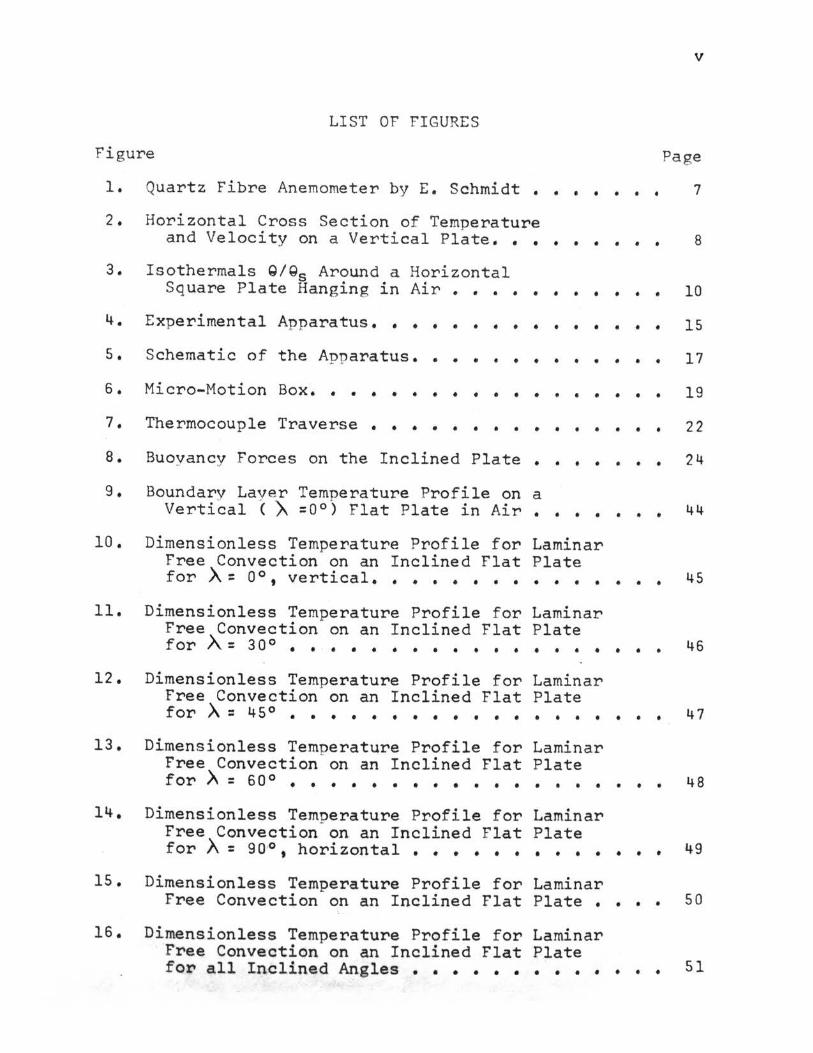
Quartz Fibre Anemometer by E. Schmidt • • • •
Horizontal Cross Section of Temperature and Velocity on a. Vertical Plate. • • • • •
Isothermals Q/Qs Around a Horizontal Square Plate Hanging in Air •••• • • • •
Experimental Apparatus •• • • • • • • • • • •
Schematic of the Apparatus ••• • • • • • • •
Micro-Motion Box. • • • • • • • • • • • • • •
Thermocouple Traverse • • • • • • • • • • • •
Buoyancy Forces on the Inclined Plate •
Boundary Layer Temperature Profile on a Vertical (A =0°) Flat Plate in Air •
• • •
• • •
Dimensionless Temperature Profile for Laminar Free Convection on an Inclined Flat Plate for )\ = 0 °, vertical. • • • • • • • • • • •
Dimensionless Temperature Profile for Laminar Free Convection on an Inclined Flat Plate for A = 3 0 ° • • • • . • . • . . . • • . . •
Dimensionless Temperature Profile for Laminar Free Convection on an Inclined Flat Plate for .)\ = 45° • • • • • • • • • • • • • • • •
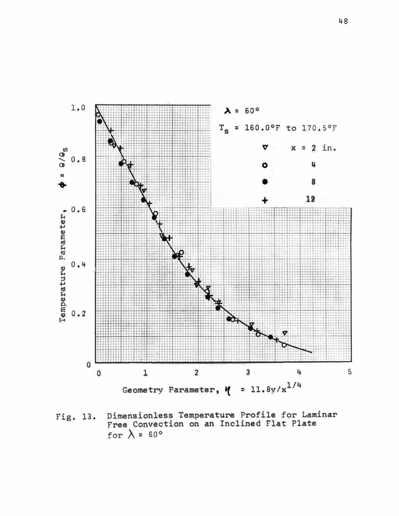
Dimensionless Temperature Profile for Laminar Free Convection on an Inclined Flat Plate for .)\ = 6 0 ° . . • • • . • • • • • . . . . .
Dimensionless Temnerature Profile for Laminar Free Convection- on an Inclined Flat Plate for X= 90~, horizontal ••••••••••
Dimensionless Temperature Profile for Laminar Free Convection on an Inclined Flat Plate •
Dimens.ionless Temperature Profile for Laminar Free Convection on an Inclined Flat Plate for all Inclined Angles • • • • • • • • • •
v
Page
0 0 • 7
• 0 • 8
• 0 • 10
• • • 15
• • • 17
• • • 19
• • • 22
• • • 24
• 0 • 44
• • • 45
• • 0 46
• • • 47
• • • 4-8
• • • 49
• • • 50
• • • 51
B
c
c
g
k
L
NGr X
NNu X
NPr
q
T
Ts
Too
vx, vy, Vz
x, y' z X
~
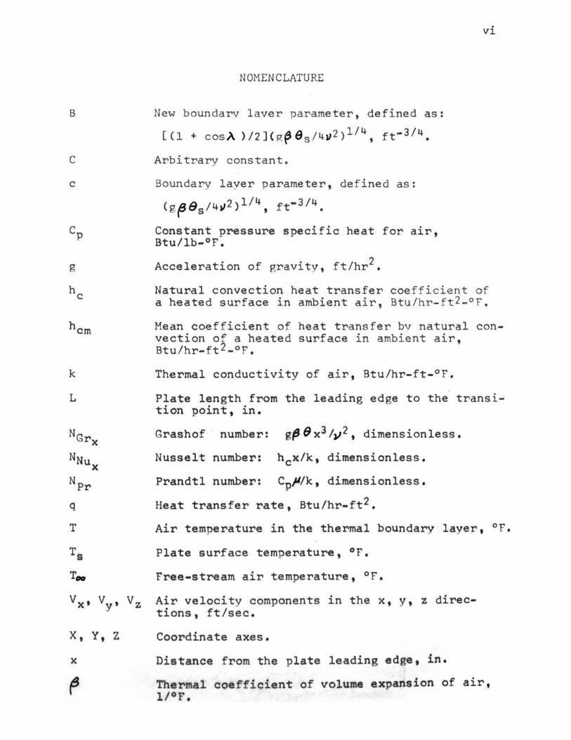
NOMENCLATURE
New boundary laver parameter , defined as:
[ ( 1 + cOS A ) I 2 ] ( g ~ 6 s I 4 J) 2 ) 1 I 4 ' f t- 3 I 4 •
Arbitrary constant.
Boundary layer parameter, defined as:
( g (J8si4 J12)ll4, ft•314.
Constant pressure specific heat for air, Btu/lb-°F.
Acceleration of gravity, ftlhr2•
vi
Natural convection heat transfer coefficient of a heated surface 1n ambient air, Btu /hr-ft2-°F .
Mean coefficient of heat transfer bv natural convection of a heated surface in ambient air, Btulhr-ft2-or.
Thermal conductivity of air, Btulhr-ft-°F.
Plate length from the leading edge to the trans ition point, in.
Grashof number: gfJ 9 x3 1,;2, dimensionless.
Nusselt number: h 0 xlk, dimensionless.
Prandtl number: Cp~/k, dimensionless.
Heat transfer rate, Btulhr-ft2.
Air temperature in the thermal boundary layer, °F.
Plate surface temperature, °F.
Free-stream air temperature, °F.
Air velocity components in the x, y, z directions, ft/sec.
Coordinate axes.
Distance from the plate leading edge, in.
Thermal coefficient of volume expansion of air, l/°F.

e e'"' ..__;
p
fl
Locdl .:=ur ternnerature d:i ffe rence : ( T - T00) , ° F •
Total t e nnerature d i fference:
Boundarv laver variable, defined a !:; : dimensionless.
l/4 cv / x ,
New boundarv laver variable, defined as:
I l/4 . . 1 Bv x , d1mens~on ess.
An~le of the inclined hot surface from the vertical oosition, de r rees.
Mass densitv of air, lb / ft 3 •
Absolute viscosit" of air , lb /ft-hr.
Kinematic viscosi tv of air, ft2/hr.
Temnerature nararneter, defined as: Q/ G , dimensionless. 5
l
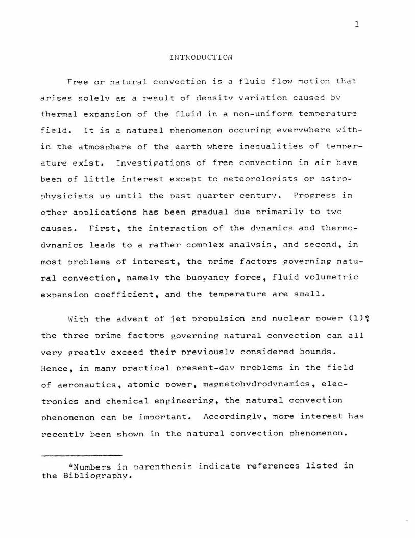
INT:RODUCTI ON
Free or natural convection lS a fluid flow motion that
arises solelv as a result of densitv variation caused bv
thermal expansion of the fluid in a non-uniform temnerature
field. It is a natural nhenomenon occuring evervwhere v..:i th-
in the atmosphere of the earth where inequalities of teMner-
ature exist. Investigations of free convection in air have
been of little interest except to meteorolopists or astro-
physicists uo until the oast auarter centurv. Progress in
other applications has been gradual due orimarily to two
causes. First, the interaction of the dvnamics and thermo-
dynamics leads to a rather comnlex analvsis, and second, in
most oroblems of interest, the prime factors governin~ natu-
ral convection, namely the buoyancy force, fluid volumetric
expansion coefficient, and the temperature are small.
With the advent of jet prooulsion and nuclear oower (1)~
the three prime factors governing natural convection can all
very greatly exceed their nreviouslv considered bounds.
Hence, in many oractical nresent-dav oroblems in the field
of aeronautics, atomic oower, magnetohvdrodvnamics, elec-
tronics and chemical engineering, the natural convection
phenomenon can be imoortant. Accordingly, more interest has
recently been shown in the natural convection Phenomenon.
*Numbers in narenthesis indicate references listed ln the Bibliography.
Heat transfer from a flat nlate 1n free convection 1.s
the more basic nroblem for i nve s ti?at ion. A nu~ber of
research pacers have been n ublished, both theoretical and
experimental, with the flat nlate 1n two narticular nosi -
tions - vertical and horizontal. Eauations and curves baserl
on mathematical analvses and exoerimental data have been
presented for various cases with the flat plate in these two
positions. However, there is limited data available on t he
inclined flat nlate.
Thus, it is worthwhile to studv free convection on a
flat plate inclined at various angles in order to acquire
more data in this area. It is the nurnose of th is inve s ti
gation to gain an understanding of the effect of anRular
nosition on the heat transfer and the critical ~rashof
number.

.3
LI TERATURE REVIEW
Generallv, the studv of conve c tive-heat trans f er can b e
divided into analvtical solutions of the convection e ~ u~-
tions and exoerimental investipations. The analvtical s olu -
tion mav or mav not be an exact mathematical solution. The
solution could be the result of an anoroximate intepral o r
numerical annroach.
Possibly the First of the few nracticable straipht-
forward solutions of the convection equation under steadv-
state conditions is due to L. Lorenz (1881, (2)). It de a ls
with the heat transfer from a vertical surface at uni f orm
and constant temnerature Tc to a colder gas in contact with ~
it, when gravity is the onlv force actin8 on the ~as.
Lorenz correctly recognized that the gas close to the sur-
face streams straight upwards, and he assumed that the
horizontal streams were neglirrible and that consequentlv the
pressure was constant in a horizontal nlane, but changed
from one horizontal laver to the next. This 1s the case of
streamline flow on a vertical wall. He further assumed that
the environment temnerature T• at an infinite distance rrom
the wall was constant and that the nronerties of gas f , ;t ,
c 0 and k were independent of temnerature. Setting un a he a t
balance for a differential section of the flowing fluid an d
integrating, Lorenz obtained the followinp. equation
( 1)

4
where C = 0.548, f o r a 1 r used bv Lorenz
This equation was a triumnh of the classi c al the orv,
hav i ng revealed for the first time the comnlex nature of the
coefficient of heat transfer b'' free convection, he, in a
form which has been shown to be valid with pood annroxima-
tion through more than half a centurv .
One particular consequence of this equation 1s that the
f h h . . Ji/<4 rate o eat exc ange, q, 1s nronort1onal to Qs~ This has
been verified in numerous exoeriments, even with fluids of
high Prandtl number. See, for examole, the work wi th
liquids bv Touloukian, Hawkins and ,Jakob ( 1948, ( 3)).
The derivation of equation (1) will not be glven, s1nce
more exact solutions are nresentlv known~ Nusselt (1 9 09,
(4)) directed attention to the fact that, according to
exoeri~ents with air, the equation becomes less exact at
Qs below 20°f and fails entirely when Qs anoroaches
zero. After that Nusselt (1910, 1915 (5,6)) oublished two
well accepted oapers, one devoted to forced convection 1n
tubes and the other to free convection in general, where he
seems to have been the first to e~nlov the nrincinle of
similaritv to the field of heat transfer. Referring to the
differential me t h od, Nusselt started ~rom the Fourier's
equation of heat conduction, the Navier-Stokes equations ~or
an incomoressible f luid and the general enerpv eauation in a
moving fluid, and obtained similarity expressio~ ~ oF the

s
form
( 2 )
JA, c,,_ pRcp2 _A/ c3 > ' 1<, v- K2 - lvp,
These equations showed that there are two dimensionless
groups called the ~rashof number (NGr) and the Prandtl
number (NPr)• which must have the same value in both svstems,
if similaritv is to exist~ Their combined effect results in
the functional relationship
( 4 )
Jakob and Hawkins (1942, (7)) by use of the dimensional
analvsis method found that
(5)
where the constant C and the exnonent n and m are determined
from exoerimental results.
Hore than 40 vears after Lorenz's fundamental investi-
gation, a series of new studies of the vertical surface
nroblem bep:an with an investigation by Griffiths and A. H.
Davis (1922, (8)). Thev determined the distribution of
velocitv and temnerature close to a vertical nlate bv direct
measurements, making use of a hot wire anemometer to measure

6
the velocity profile. The surface temperature was kept
uniform during the experiment. First of all, using a plate
3 or 4 feet high, they verified Lorenz's result that h in
creases with the fourth root of the height. This result, as
is well known, involves the existence of laminar flow.
Employing, further, a plate 9 feet high, the authors found
that at a distance of about 1/5 in. from the surface and
above a certain height neither the velocity nor the tempera
ture increased any more. They concluded that the strata of
air nearest the plate were not themselves carrying away the
heat from the upper part of the surface, but merely trans
mitting it to the outer layers which carried it awav.
Avoiding some oversimplifications made by Lorenz,
Nusselt and Jurges (1928, (9)) succeeded in essentially im-
proving the theory with their experimental work. asure-
ments of the field of temperature near a vertical hot plate
with very thin thermocouples were first made by Nusselt and
Jurges in their experiments, but they could not measure the
field of velocity in default of a suitable instrument for
these small velocities. The most elaborate improvement,
however, is due to E. Schmidt and Beckmann ( 19 30, ( 10)), in
cooperation with Pohlhausen, who found a way to integrate
the differential equations set up by these authors. The
experimental part of their work consisted in the determina
tion of the velocity and temperature field close to the sur
face of electrically heated vertical plates of about 5 and

20 in. height. The temperatures were measured by a thermo
couple with wires of 0.02 mm diameter. As to the air
velocities, E. Schmidt solved this problem with his quartz
fibre anemometer shown in Fig. 1, consisting of a straight
I""" ) c 6 A
b ~
Fig. 1. QUARTZ FIBRE ANEHOMETER BY E. SCHMIDT a. Quartz fibre b. Support pin c. Tube of the microscope
7
fibre of quartz about 0.02 mm thick, 1 to 2 em long, fixed
at one end, and placed in the field of velocity. This
quartz fibre is bent elastically by the flow of air passing
it perpendicularly to its length. The deflection of the
end of the fibre is measured with the help of a microscope,
located several centimeters away from the fibre in order
not to disturb the flow where the velocity is measured. The
calibration shows that the deflection was not proportional
to the velocity. This instrument which allowed for the
measurement of air velocity down to a few millmeters per
second, enabled E. Schmidt and w. Beckmann to measure the
whole field of velocity. Curves of temperature T and
vertical velocity vx in hQrizontal 1 nes at different
heights x above the plate are given in Fig •. 2.

T 40
ao
2IJ
10
.M
C""~e I
~
20
"
0o~--~,z~---.~~~---o~.,~--o~ .• ~c-~~~o )'
Fig. 2. Horizontal cross section of (a) the field of temperature T and (b) the vertical comnonent V~of velocitv before a vertical plate 12 em hiph and heated to about 66 C in air of 15 c, measured at different vertical distances x above the lower edge of the plate (E. Schmidt and w. Beckmann, 1930, (8))
This exoeriment proved that the hot a1r motion near a
flat plate is confined to a rather thin laver which allows
for the simplification of boundary layer theory. Having
these experimental results be f ore him, E . Pohlhausen (1930,
(10}) found the mathematical solution of the nroblem.
8

Pohlhausen introduced instead of the vertical coordinate x
and the horizontal c oordina te v, the independent variable
' cv/x~, where c::: 5.885;': is a parameter p:iven by the vi s -
cosity and buoyancy of air at the plate temnerature Ts~ The
resultant oartial diff erential e quations of velocitv and
temperature change to nonlinear but ordinary ones contain-
ing onlv derivatives up to the third order in the new
independent variable. Pohlhausen then obtained
-- ( 6 )
Kimball and W. J. King (1932, (12)) through a theore t-
ical investigation, which 1s based on the observation that
the velocitv maxima (Fig. 2) occur at places where Q=Qs/2,
found results which agreed with Schmidt and Beckmann's
observations.
Continuing the studv R. Weise (1935, (13)) with his
experimental work determined valves about 25 % higher than
Eq. (6). This may be oartlv due to the influence of the
edges and to motions of the ambient air. Schmidt observed
that even a small disturbance by any motion around the edges
increased the heat transfer by several percentage points.
w. J. Kin g (1932, (14)), J a kob and Linke (1933, (1 5 ))
and McAdams (1942, (16)) have obtained curves and equations
* c=@!ft!for air in laminar flow.

to correlate the exnerimental data. ,Jakob recommends
for the laminar range where N~r • Npr = 10 4 to 108
and I
NNu= 0./29 ( NG,- • Np,)3
for the turbulent ranpe where NGr • NPr = 108 to 1012.
R. Weise (1935, (13)) tvas amonR the first to measure
10
( 7)
( 8 )
the temperature distribution on a horizontal nlate. He used
square aluminum nlates, o f 16 and 24 em, 1.0 and 1.5 em
thick, resnectivelv. These nlates were susnended in a lar~e
room and heated electricallv. The results of a total of
70,000 readings were combined to show the different natterns
of isothermal lines. One of these natterns i s renroduced as
fig. 3. According to these graohs, which varv sli ghtly in
~ ~~:w~-~~~
~~~~~~::~~~~==~~~~~==::s~=~~~ o.eeF ~ f f t f f ~ f i 1~ c•J
~~~~~~~~t~[··~ . ;; ~ :~-
Fig. 3. Isothermals ~/Qs around a horizo~tal square olate han g ing in air.
Q, Qs=excess of air and . surface temperature, respectivelv, above air temperature at far distance. Le f t side of fi g ure: cross section parallel to nla t e edge ; rip,ht side of f i gure: cross section through plate diagonal. From R. Weise (1935, (13)). .

11
di f ferent nlanes through the vertical axis, it is observed
that on the bottom side of the plate the boundarv laver 1n
which the temperature droP is concentrated is about 1.5 em
thick in the center and 1 em thick close to the edge. Above
the plate cold air is flowing from the edpe to the center,
causing a depression of the isotherms close to the plate at
the center. Weise then calculated individual coefficients
of heat transfer from the temnerature drop close to the
plate, to check the mean coefficient as found bv direct
measurement and found good agreement. Kraus (1940, (17))
has, in addition, determined the corresnonding velocitv
fields. Below the plate, orderly motion was observed an-
preaching the nlate and then moving outward toward the
edp:es. Above the plate, random vortices were noticed.
~ighest velocities occurred 1n the vicinitv of the edges.
The momentum boundarv laver on the lower side of the nlane
exceeded considerablv the thermal boundarv layer in thick-
ness, even in air with Npr = 0.72.
The larpest heat transfer coefficient on a horizontal
Plate with free convection must be expected to coincide with
the highest velocitv, i.e., it should occur near the edges.
The larger the plate, the smaller the influence of this
effect on the entire heat transfer. The overall heat trans-
fer coefficient thus becomes more and more independent of
the size of the nlate as the nlate size increases. A
dimensionless relationshiP of the form NNu = C(NGr •Nprl 113

12
is to be exne c ted. The choice of the characteristic length
in the Nusselt and Grashof numbers is thus unimnortant, so
that either the width or the diagonal or even, as nronosed
bv Weise, the circumference can be used. The measurements
of Weise and Krause on plates of 16 bv 15 em to 26 bv 26 em
1n air and with excess temperatures of the olate ranginp
from 122 to 662F can be correlated satisfactorily by the
equation
I
NNu =0.137( Nor·Np,.) 3 ( 9 )
Another method useful in the study of free convection
1s the optical method. The difference of density and light
velocity close to a heated surface can also be used to nro-
duce interference fringes. Eckert and Soehnghen (1948, 1951,
(18, 19)) used an interferometer to study the mechanism of
natural convection and obtained good results.
Y. P. Chang (1957 9 (20)) has presented his own idea on
natural convection. Instead of approaching the problem
according to conventional concepts, a short-cut method is
introduced by the application of wave motion. Above the
heating surface a boundary layer lS assumed whose thickness
depends upon the heat flow. Inside this laver there 1s wave
motion, stable in the lower nart but unstable in the unper.
It has been recognized that, if there is a temperature
gradient across a stratum of fluid, a wave motion will occur.
Each loop of this wave can initiate vortices in the free
l. 3
convection orocess. Although the calculated results a~ree
excellentlv with exoeriments as conducted bv nrevious in
vestigators the theorv is still not soundlv established.
Although the nrevlous discussion indicates extensive ln
vestigation of free convection on vertical and horizontal
plates, there has been a limited amount of work done con
cerning free convection on a flat plate at angles of ln
clination between the vertical and horizontal.

14
EXPERIMENTAL WORK
Description of the Apparatus
A picture of the apparatus used in the investigation is
shown in Fig . 4, and a schemetic of the function and arrange
ment of the parts is shown in Fig. s. To facilitate the
study of free convection on the flat plate in various posi
tions the hot surface of this apparatus can easily be moved
through all inclined angles with the vertical, from the hot
surface upward through the vertical position to the hot
surface downward. Heat is supplied at the bottom of the
flat plate in an even distribution through the use of
electrical resistance heating elements. The plate is large
and of sufficient thickness to allow for an even distribu
tion of the heat generated by the resistance elements. When
steady state is reached the surface temperature distribution
is uniform over the entire plate surface. A movable thermo
couple of extremely fine wire at the end of its hot junction
was used to record the temperature at predetermined points
above the hot surface of the plate.
Test Plate
An aluminum alloy plate was used as the hot surface.
Aluminum was used because of its light weight and resultant
ease of handling, and because of its high thermal conductiv
ity to allow for a more even temperature distribution in the
plate. The dimension of this finished rectangular piece
were 26-27 /32 in. length, 7 in. width and 11/32 in. thickness.

15
Fig. 4. Experimental Apparatus

KEY to F'ig4 S
1. Flat elate (Aluminum allov)
2. Electrical resistance heating elements
3. Insulating board
4. Soecial holes in T tvpe aluminum bar o f 5/S ~n. Qiameter
5. SunnortinR bar with threads and nut
6. Hot junction of the detecting thermocounle
7. Micro-motion box
8. Rai 1
9. Guide bars
10. Autotransformer /
11. Movable arms
12. Movable base
13. Potentiometer
14. Ice bath
15. Thermocouple holes
16. Thermocouple wires
17. Frame
18. Base

- +
27 11
2632
@ 14
Fig, 5, Schematic of the Annaratus

18
The hot surface exposed to the air was super-f inished to a
flat tolerence of :!: 0.002". Four equally spaced holes were
drilled in each side edge of the plate to allow for inser
tion of thermocouples.
PoW'er Sup·ply
The heating elements wer'e locatect at the bottom of the
aluminum plate. Ten electrical resi.sta,nce elements were
employed. A large nu,mber of holes weN drilled in the T
type aluminum guide bars and the adjacant transite insulat
ing bar to- provide flexibility in the hook-up of the resi.st
ance elements to the power supply. The heater elements can
be series connected, parallel, or parallel and series con
nected as necessary to achieve the desired temperature levelt
A variable a~totransform~~ was used to control the power
supplied to ·the re.sistance elements and thus con.trol the
te.mperature. A 7 /8" thick insu;t~ting ba~l'd w·as located
below the electrical heatin.g elem.ents to limit the heat flow
in this direction. On both side ·edges of the aluminum plate .
were two 1/2 in. thick transite plates also used for insula-
tion. Two T-type alu~inum bars were employed to support the
plate and these insulators.
Pet·ectina ·Thermoc·oup·le
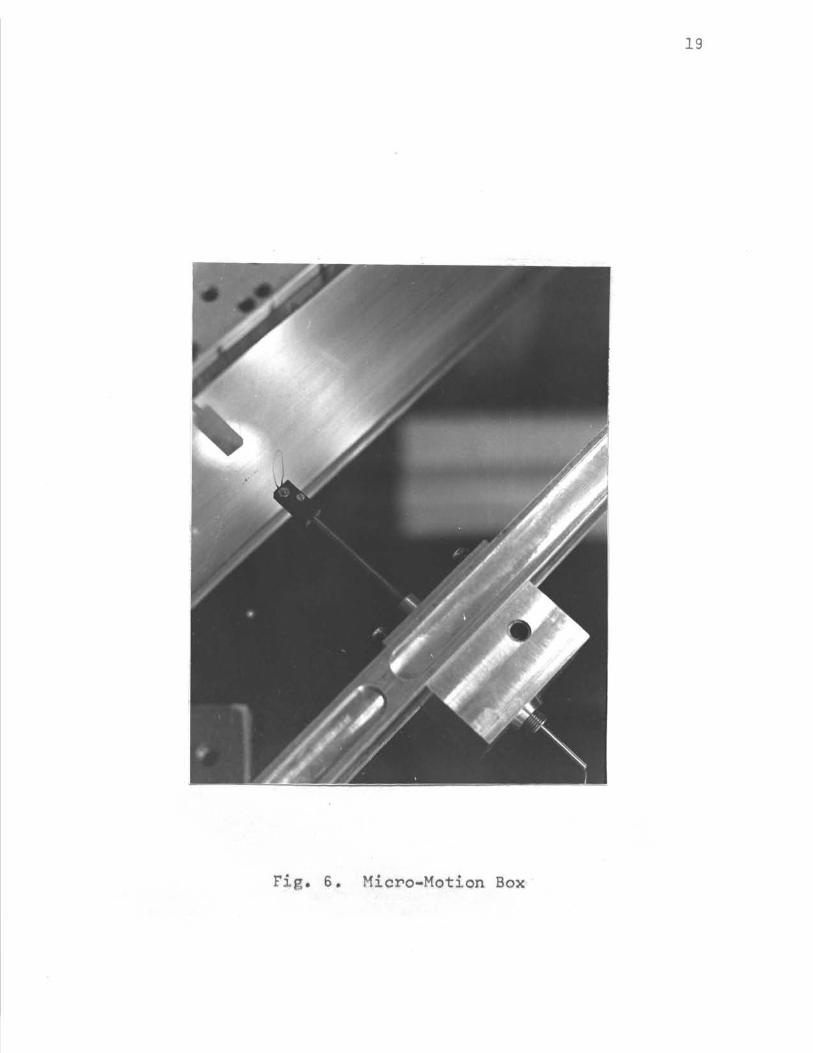
~ shown in Fig. 6 1 a No. 28 g~ge B & S copper- cons tan
tan thermocouple was used to measure. the temperature in the
*See Appendix l(A)
19
Fig. 6. Micro-Motion Box

20
free convection thermal boundary layer. The copper and
constantan wires were ground to less than 0.002 in. in
diameter at their ends and joined by mercury solder with the
junction diameter reduced to less than 0.004 in. The influ
ence of the insertion of this extremely fine thermocouple
into the thermal boundary layer is negligible*. Its sensi
tivity is also sufficient to accurately determine the
temperature profile within th.e thermal boundary layer.
This thermocouple was held by a stainless steel tube of
3/16 in.O.D. The thermocouple was attached to the end of
the tube by a plastic bracket. The material of which the
bracket is made has good insulating characteristic through
out a large temperature range. This rigid mounting of the
thermocouple and plastic bracket to the stainless steel tube
prevented any motion in the sensing e.lement of the thermo
couple. The steel tube was inserted into the motion-screw
of the micro-motion box with a force fit. The micro~motion
box contains a wo~ and gear set to obtain a very small
displacement of the thermocouple for each revolution of the
dial. Each turn of the dial results in a displacement of
29.8/10,000 in. of the thermocouple. The dial is divided
into eight divisions, so that the smallest displacement of
the thermocouple is 3.6/10,0.00 in. (See Fig. 4 and Fig. S).
The micro-motion box was moved along two !-beam aluminum
rails. The micro-motion box was easily adjus.ted to any
*See Appendix l(B)
21
desired position along the length and width of the plate.
Two thermocouples (.24 gage, B & S il;'on-constantan)
were used to detect the plate temperature at eight positions,
four on each side edge of the plate (Item 15, Fig. 5). A
pair of bars with several slots cut along th.eir length were
used to adjust the position of the aluminum plate. A
movable base was also employed to allow for more adjustment
of the flat plate.
22
ANALYSIS OF THE EXPERIMENTAL RESULTS
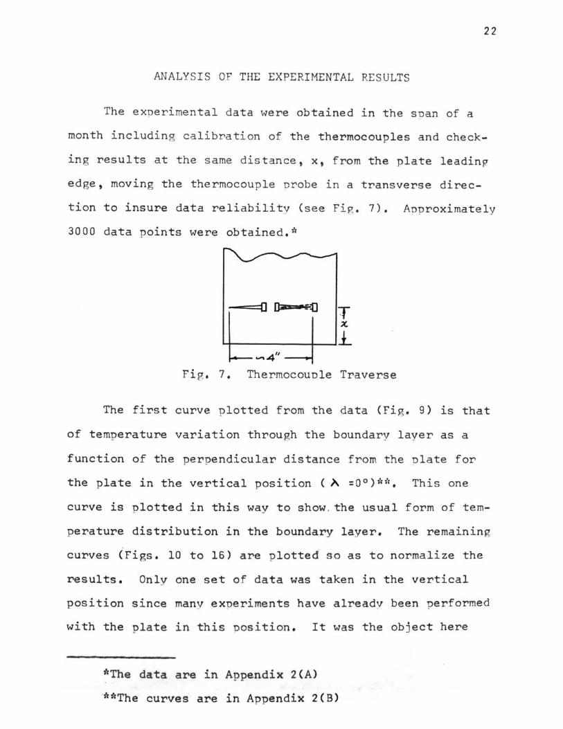
The experimental data were obtained in the span of a
month including calibration of the thermocouples and check
ing results at the same distance, x, from the plate leadin~
edge, moving the thermocouple probe in a transverse direc-
tion to insure data reliability (see Fig. 7). Anproximately
3000 data points were obtained.*
T X
'+---------1--lj_ ..... 4" _ ......,.
Fig. 7. Thermocouple Traverse
The first curve plotted from the data (Fig. 9) is that
of temperature variation through the boundary layer as a
function of the perpendicular distance from the nlate for
the plate in the vertical position ( A. =0°) 'id;. This one
curve is plotted in this way to show . the usual form of tern-
perature distribution in the boundary layer. The remaining
curves (Figs. 10 to 16) are plotted so as to normalize the
results. Only one set of data was taken in the vertical
position since many exneriments have already been performed
with the plate in this position. It was the object here
*The data are in Appendix 2(A)
**The curves are in Appendix 2(B )
23
only to comoare the data taken in this nresent investipation
with previous work to determine any error in the methods
used. The results were in very good apreement with the
experimental work of E. Schmidt (1930, (10)). However, \·lhen
the nresent data are compared to that of ~Aleise (1933, (13)),
this present data are aonroximatelv 25 ner cent lower.* fip.
10 shows the data for the vertical plate case including some
of the data from Schmidt for comparison.
Next, a new variable was introduced as suggested bv E.
Pohlhausen in E. Schmidt's naner (1930, (10)) of the f orm
(10)
Bv changing the units into British units the constnnt c
becomes 11.8 instead of 5.865 as in Schmidt's work. The
results are in excellent agreement with both E. Pohlhausen's
mathematical analvsis and E. Schmidt's experimental work.
Fig. 10 o f Anoendix 2(8) shows this result. It is annarent
that equation (6) from the Literature Review, develoned bv
E. Schmidt, is still recommended hv the aut:tor's work for a
flat plate in the vertical position with free convection in
air. This equation lS
(11)
During the exoeriment the author found that the nrofile
*See the Literature Review.
2 4
of the temnerature r,radient in the boundarv laver of the
f lat nlate in an inclined o osition is not as f irs t ima pined.
Instead of a thick boundarv laver as a result of the n l a te
inclination, there exists a thin laver alonp the surface of
the hot plate in both the laminar and turbule n t f low re g i ons .
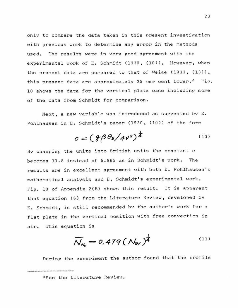
Consider a small element dv in this boundarv laver with the
buovant force ~iven bv <9ff 8) resolved into two comnonents ,
one along the hot surface and the other oerpend icular to the
hot surface, as shown in Fi g * 8. The only e f fe c tive force
of the fluid flow is ds which 1s along the hot surface and
is equal to <ffP{89> cos)\ • If the temperature is not too
high (in this exnerimental investigation a temn erature di f -
Fig. 8. Buovancv Forces on the Inclined Pl a te
f erence of ove r 350°F resulted in a n unstable thermal bound-
ary laver) the air flow will be laminar near the leadin g
edge and some distance alon g the nlate and wi ll then nas s
t hrou gh a tra ns i t i on stage and f i nallv become turbule nt.
In 1960 F . Kreith (1960• (21)) considered the inclined

25
nla.t:e and inserted COSA into the eauation P.J.ven bv E. ~ . P . •
Eckert (1948, (22)) for free convection from a heated verti-
cal plate. This new equation then becomes
--It is apparent in equation (12) that as the anple, A , a n -
nroaches 90°, the Nussult number, NNu• annroaches 0, which
means that in the horizontal position no heat is trans f erred
bv free convection. It becomes obvious, then, that the
interaction of the dvnamics and thermodvnamics of the fluid
must be considered be f ore a valid relationshio can be ob-
tained for Nusselt number as a function of the flat nlate
angular position.
In Fig. (10) through (15) are shown the results of the
inclined plate tests. The abscissa is the geometry narame-
ter, ll.By/~, and the ordinate is the dimensionless temner-
ature ratio, GIGs• Plotted in this wav the data for a e1ven
angle of inclination, ~, with different hei ght , x, above the
leading edpe of the heated olate forms a sin~le curve. The
slope of the curve, d~/d~, decreases as the angle of i nclina
tion, A, increases, as shown in the comoarison curve, Fig.
15. Several attemnts were made to attain a new variable to
transform this familv of curves represented in Fig. 15 into
one curve. Multio1vinp the coefFicient, c, given by equa-
. < 1 +cos .A ·. 1 . tion (10) by the express1on 2 ' r es u ts 1n a conver-
gence of the familv of curves shown in Fig. 15 to a single

26
curve, as s hown in rig. 16. Thus, the new coefficient, B,
becomes
( 13)
From equation (13) it can be seen that for the vertical
plate (A = 0°), the coefficient reduces to the value p:i ven
by equation (10), and for the horizontal nlate ()\ = 90°),
the coefficient becomes one-half the value given bv equation
(10). For comparison, McAdams (1954, (24)) recommends, for
a horizontal heated plate facing downward, an equation of
the form
(14)
In this equation, C is a constant which takes on the averare
value of 0.26. With the Prandtl number for air taken as
0.733, and the constant C of 0.26, equation (14) then be-
comes
(15)
For the case of a vertical heated nlate L. Schmidt
(1930, (10)) recommends equation (11) of the form
(11)
Thus, equations (15) and (11) f or the horizontal and verti
cal heated plates differ onlv in the constant. The constant
in the horizontal case is anproximatelv one-half that of the
27
vertical. This condition is satisfied bv the choice of the
coefficient, B, given bv enuation (13).
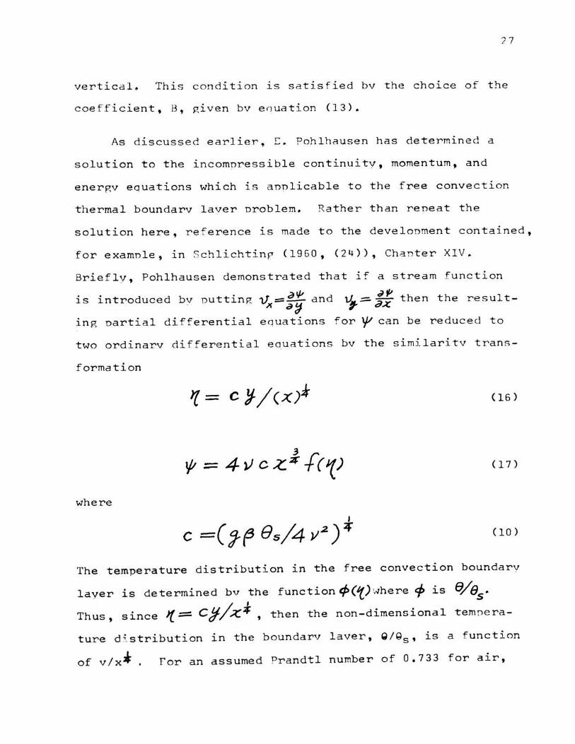
As discussed earlier, E. Pohlhausen has determined a
solution to the incomnressible continuity, momentum, and
energv equations which is anplicable to the free convection
thermal boundarv laver nroblem. Rather than reneat the
solution here, reference is made to the develonment contained,
for examnle, in Schlichtinp (1960, (24)), Chanter XIV.
Briefly, Pohlhausen demonstrated that if a stream function
is introduced bv puttinf! 1f =~ and x a:J
~~ v,.= ax then the result-
1ng oartial differential eouations for ~ can be reduce d to
two ordinarv differential eauations bv the similaritv trans-
formation
(16)
(17)
where
(10)
The temperature distribution in the free convection boundarv
layer is determined bv the function tP('() '..Jhere t:j> is
Thus, since J( = Cj/A::.-;f , then the non - dimensional tempe ra-
ture d i stribution i n the boundarv laver, Q/Qs , is a f unction
of v/x* . for an assumed Prandtl number of 0.733 for air,

28
it can be seen in Fig. 10 that the experimental results of
this investigation for the plate in the vertical position
agree very well with the Pohlhausen development.
Substituting the new parameter, B, given by equation
(13), for c in equation (16), results in a new expression
for ~' of the form
(18)
Now, the non-dimensional temperature distribution in
the boundary layer Q/Qs• is a function of y/x• and the plate
inclination, )\ • With a Prandtl number for air of 0. 733,
the experimental results of this investigation for all in
clined angles agree with the m,odified Pohlhausen development
given by equation (18). This is shown in Fig. (10) to (14).
With the temperature distribution known, the quantity
of heat transferred per unit time and area from the flat
plate to the fluid at section x is given by
tz(x.)=-k(JT.) =h6 6 i7/f 1~=0 c s
(19)
Equ~tion (19) indicates that the heat is transferred from
the plate to the fluid by conduction through a ve.ry thin
layer adjacent to the plate. Using the above development,
the temperature gradient at the wall, (aT/ t3 ~) j :::so
is determined to be
t

2 9
(/0)
For a Prandtl number for air of 0.733, ;J<P/aH) = - o . .5o 8 l. t=o
thus
and q becomes
( 2 2)
The local heat transfer coefficient on a flat nla te a t
some nosition x is then P.iven by
he= 0.508 k B ~-~ (23)
where B is defined bv equation (13) as
Since the local value of the Nusselt number, NNux' 1s g iven
by
(24)
then equation (23) can be written in the form
NNu,x = 0. 36 [ ( / + COS .A)/ 2 J • ( Nt;r~)~ ( 2 5 )
where N is the local ~rashof number at the nosition x, Grx
given by

30
(26)
Equation (25) can be used to determine the value of the
local free convection heat transfer f rom a heated flat plate
at any angle of inclination, )\ , from the vertical throu~h
the horizontal, the hot surface of the plate facing downward
in the horizontal and inclined positions.
The heat transferred from a flat nlate of unit width
and length L per unit time is given by
Thus, the mean heat transfer coefficient, hem• becomes
(28)
where B is defined by equation (13) as
(13)
Since the average value of the Nusselt number, ~Nu' is given
by
{:[ = hemL/J< N,
(29)
then equation (28) can be written in the form
i\l;. = o. 48 [(I+ cosA)/z]· (N6 ,.)f <3o>
where NGr is the Grashof number for the. J:>late of length L L

31
from the leading edpe to the transition noint, riven bv
( 31)
Equation (30) can then be used with good accuracv to
determine the laminar free convection hea t transfer fro~ a
heated flat nlate for anv angle of inclination, ~ , from the
vertical throuph the horizontal, the hot surface of the
nlate facinR downward in the horizontal and inclined oosi-
tions.
32
DI SCUSSION AND RECOMMENDATIONS
It was the orlmarv ob~ect of this investipation t o at-
tain a solution for free convection heat transfer from a
heated flat plate in the vertical and horizontal oositions,
and three inclined nositions between the vertical and
horizontal. The hot surface of the Plate was facing down-
ward for the horizontal and three inclined positions. The
original plan was to study the mechanism of free conve c tion
through direct temperature measurement in the therr.1al b ound-
ary layer using a thermocouple, and through the use of a
modified Schlieren svstem to get a nicture of the temPerature
gradient in the thermal boundarv laver. This latter method
was abandoned after more than a month of trving to adant an
existing modified Schlieren system to fit the needs of this
investigation. Further, the original ulan called for a
measurement of the velocitv nrofile in the boundarv laver
through the use of a quartz fibre.* However, such an a r
rangement could not be obtained so no velocitv measurements
were made. A more complete nicture of the free convection
heat transfer problem could have been obtained had it been
possible to measure the velocity Profile in addition to the
temperature profile throup,h the boundarv laver.
The data plotted ln Fig. 9 throuph 16 came from nlate
surface temneratures, Tc, ranpinp from 150°F to 170°F. .::;,
These
*See the Literature Review.
data are the most reliable and are comnarable to that of
Schmidt (10) Weise (13), a nd others. In the case o f the
nlate surface temnerature of annroximatelv 120°F, the dif
ference between the ambient temnerature and the nlate tern-
nerature is small. Any variations in the room temnerature
would then exert a substantial influence on the results
obtained for temnerature in the boundarv laver~ Thus, it
is imoortant to be able to control the ambient temnerature
ln order to prevent this effect on the results.
33
The data obtained for plate surface temneratures ln the
range of 300°F to 400°F were likewise inconsistent. Larpe
fluctuations resulted from small disturbances in the svstem
which prevented a thorough investigation in the hiRher tem
perature range. If the modified Schlieren svstem could have
been adapted to this investipation, then it is believed that
this inconsistencv in the thermocounle readinrs could have
been explained.
Near the leading edge of the flat nlate (within ab out
1 inch), the thermal boundary laver was difficult to deter-
mlne. Schmidt (10) note d this difficultv in his work on
he a ted vertical nlates. It is believed tha t the low value
of the momentum,fV, resulting from the low air velocitv,
V, at the plate leading edge results in a flow cond i tion
wh i ch i s e a silv influenced bv local disturbances. As s oo n
as the air has a c cele r a t ed s ome s hor t d i stance un the pla t e ,
its momentum has increased. The flow then becomes more

34
stable and is less influenced by local disturbances.
It is recommended that equation (30) be used to deter
mine the average value of the laminar free convection heat
transfer from a he~ted flat plate at any angle of inclina
tion from the vertical through the horizontal. The hot sur
face of the plate faces downward in the horizontal and in
clined positions. Equations (30) and (31) are repeated here
(30)
where NGrL is the Grashof number for the plate of length L
from the leading edge to the transition point, given by
(31)
For the smooth flat plate in the vertical position the lami
nar flow region extends to a plate length of ·12 in. with a
corresponding Grashof ·. number of 4. 0 x 10 8• In the hori zen
tal position, hot surface downward, the upper limit on the
Grashoff number for the tests was 3.0 x 101°. For the inter-
mediate inclined positions of )\ = 30°, 45° and 6.0°, the
laminar flow extends to a plate length of 14 in., 18 in.
and 20 in., respectively. This corresponds to Grashoff
a . . 109 for ''5° numbers of 6.4 x 10 for 30° inclJ.nat~on, 1.4 x .,.
inclination, and 1.9 X 10 9 for 60° inclination.

35
BIBLIOGRAPHY
1. s. Ostrach, "New Aspects of Natural-Convection Heat Transfer", Trans. ASME, Vol. 75(1953), pp. 1287-1290.
2. L. Lorenz, "Uber das Warmelei tvermogen der Metalle fur Warme und Elekrizitat," Wied. Ann. Phys., Vol. 13 (1881) pp. 442-582.
3. Y. s. Touloukian, G. A. Hawkins and M. Jakob, "Heat Transfer by Free Convection from Heated Vertical Surfaces to Liquids," Trans. ASME, Vol. 70, (1948), P• 13.
4. w. Nusselt, Forchungsarb . a. d. Geb.d. Ingenieurwes, Nos. 63 and 64, (1909).
5. w. Nusselt, "Der Warmeubergang in Rohrleitungen," VDIForschungs-Heft, No. 39 (1910).
6. w. Nusselt, "Das Grundgesetz des Warmeuberganges," Gesundh.-Ing., 38 (1915), pp. 447-490.
7. M. Jakob and G. Hawkins, E'lements· of Heat Transfer and Insulation, John Wiley and Sons-;-New-York, (1942r.-
B. E. Griffiths and A. H. Davis, Food Investigation Board, Spec. Rept. 9, Department of Scientific and Industrial Research, H. M. Stationery Office, London, (1922).
9. W. Nusselt and w. Jurges, "Das Temperaturfeld uber einer lotrecht stehenden geheizten Platte," z. VDI, 72 (1928), p. 597.
10. E. Schmidt and W. Beckmann, "Das Temperatur- und Geschwindigkeitsfeld von einer Warme abgebenden senkrechten Platte bei naturlicher konvektion," Tech. Mech. u. Thermodynam., 1 (1930), pp. 341-391.
11 . D. Meksyn, New Method in Laminar Boundary-Layer Theory, Pergamon~ess, (19~), P• 177.
12. w. s. Kimball and w. J. King, "Theory of Heat Conduction and Convection from a Low Hot Vertical Plate," Phil. Mag. (7) 13, (1932), pp. 888-906.
13. R. Weise, "Warmeubergang durch freie Konvektion an quadratischen Platten Forsh , " Gebiete Ingenieurw. , 6 (1935) p. 281.

14. W. J. Kin~, "The Basic Laws and Data o f Heat Transmission," l'1ech. Eng., Vol~ 54 (1932), ~ ,~.., , 347-353~
15. M. Jakob and W. Linke, Forch. Gebie Inrenieurw., 4, (1933), ry n . 75-78.
3G
16. 1-J. H. HcAdams, Heat Transmission, 2nd Cd., HcGraw-Hill Book Co., New York, (1942}.
17. I.J. Kraus, "Temoeratur- und Geschwindipkeitsfeld bei freier Konvektion urn eine waagerechte quadretisch Platte," Phvsik. z., 41 (1940), n. 126.
18. r:. R. G. Eckert and E. SoehnP,hen, "Studies on Heat Transfer in Laminar Free Convection with the ZehnderMach Interferometer," USAF Tech. Report 5747, (1948).
19. E. R. G. Eckert and E. Soehnghen, "Interferometer Studies on the Stabi1itv and Transition to Turbulence of a Free Convection Boundarv Laver," Proc. of the General Discussion on Heat Transfer (London: ASMEIME, 1951), po. 321-323.
20. Y. P. Chanp, "A Theoretical Analvsis of He~t Transfer in Natural Convection and in Boilinp:," Trans. ASME, Vol. 79, (1957), nn. 1501-1613.
21. F. Kreith, Princinles of Heat Transfer, International Textbook Comoanv, Penn., (1961), on. 330-331.
22. E. R. c:;. Eckert and Thomas H. ,Tackson, "Analvsis of Turbulent Free-Convection Boundarv Laver on rlat Plate," NACA TR 1015, 1950.
23. Paul L. Geirnger, Handbook of Heat Trans fer Media, Reinhold Publ ishlng Corn:-; New York ' ( rgs 2) ' DD. 2 9-32.
2 4. !{. S ch li ch t ing, Bounda rv Laver Theorv, 4th Ed. , ~1cr-ra~JHi11 Book Co., Inc., New YorK", (1960).

37
VITA
The author. Shu Chien Yung. was born on November 13,
1936 in Chengdo. China. He received both his high school
and college education in Taipei. Taiwan. China. A Bachelor
of Science degree in Me.ch.anical E~gineering was received
from National Taiwan Univer~:Jity in June 1959. After gradu
ation the author s-erv·ed in the Chinese Air Force for one
and a half years. Upon discharge in February 1961 he ac
cepted employmen~ with the China Textile Industrial Corpora
tion.
In October of 1963• the author left for the United
States to continue his studies by working towards the degree
of Master of Science in Mechanical Engineering at the
University of Missouri at Rolla.

38
APPENDIX l
(A) Power Sunnlv ·~-. ~..,.. """-----·-
The nower sunnlv for heating the f lat nlate 1n th i s 1n-
vestigation used a variable transformer sunnlvin? enerRv to
the heating elements connected in series. The author found
that the temperature distribution was good for most tempera-
ture ranp,es investirated. Thus, the snecial arrangement of
oarallel or series-narallel f or the heater elements was not
needed.
(B) Detecting Thermocounle
a. In 1931 E. Schmidt also used a thermocounle 1n his
exnerimental work. His thermocouple of 0.02 rnm diameter was
considered small enou gh to make its nresence in the boundarv
laver of no effect.
b. Several configurations were tried before a satis-
factory arrangement was realized fo r the detecting thermo-
counle. First, the thermocounle nrobe was made bv us1ng a
fine circular ceramic tube of snecial design ( Fi g . a), hav-
in g two small holes inside t he tube for insertion of the
thermocouple wires. Da ta were t aken at the s urface us1ng
this device and comnared with the nlate temnerature indicated
by the thermocouole inserted in the holes locate d along the
plate edge. The correlation was not good. Temneratures
were also determined in the thermal boundary layer using

this device and the data compared with E. Schmidt and
Eckert's (1948, Cl8)) data. Again, the comparison was not
FRONT SID&
" t
Fig . a
39
good. It is the opinion of the author that this arrangement
results in a large conduction et'ror because the temperature
in the Y direction is large, and because the disturbance in
the boundary layer is considerable. Moreover, the motion of
the thet'mocouple was difficult to control because of the
lack of physical support for the ceramic insulator which
holds the thermocouple wires. Other attempts were made to
achieve a satisfactory arrangement with the final device
used in the investigation shown in (Fig. b). Here the
thermocouple. was attached to a small rectangular plastic
piece, w·ith the extremely fine thermocouple wires extending
parallel to the hot surface and the plate leading edge to

1«40'4'///U/1//U//UpA _ .... t_--t,...,.z
HOT. JUHC.TIOH' -.---
X
t VIEW A
VIEW A
lig. b
reduce the conduction error along the thermocouple INlres.
With the temnerature assumed constant in the Z-direction, we
can sav that the temperature of the hot junction is the same
as the temnerature of that point which it occunies, and
there i s no conduct i on error uresent. rurther, because of
the s mall size o F the ~unction and wires, there is neplipible
influence due to the presence of the thermocouole in the
boundary layer.

4 1
AP PENDIX 2 : Test Procedure
Onlv the imnortant stens required 1n the test nrocerlure
are listed here.
1. The nlate was heated bv selectinp the annrooriate volt
age settinp on the variable transformer to allow electrical
energy to flow through the resistance heaters. A neriod of
from two to three hours was necessarv to allow the nlate to
reach a steadv state temnerature condition before data could
be taken.
The steadv state condition was determined bv monitori nr
the eipht thermocouples inserted in holes located in the side
edges of the flat nlate (see fig. 5). When there was no
change 1n the thermocounle reading for a neriod of from
twentv to thirty minutes, it was assumed that the plate had
reached a steady state condition.
2. An ice bath was nrenared and used as the cold-iunction
reference temoerature.
3. The barometric pressure and room temperature were re
corded.
4. The thermocouples were calibrated at two noints: the
boiling point of water; a n d room temne r ature, c omoa r i nr the
thermocouple wi th a calibrate d thermometer.
5. The detectinp thermocounle was nositioned at a nre-

d et e rmined noint. The emf indicated on the notentiometer
w.Js recorded and later converted to ternnerature. The detect-
lnP thermocounle was then moved throuph the boundarv laver
~t selected points along the nlate and the above nrocess
reneated.
6. The procedure indicated in Item 5 above was reneated for
each anpular position of the nlate and each plate temperature
condition.

4 3
APPENDIX 3(A)

180 lr t J T9 = 160.0°F to 170.5°F
~ 0
Fig. 9.
•iH
+-
0.2 0.3 0.4
Distance Perpendicular to Plate, v - in.
Boundary Layer Temperature Profile on a Vertical ( h = 0°) Flat Plate in Air
44
o.s

45
1.0 M: ;... = 0°, vertical
Ts = l60.0°F to 170.5°F
0 x = .38 in. A X = .5 ine f1J
Cb ......... o. 8 a .77 • 1 Cb
II H + 1.54 • •
2
0 0
Fig. 10.
f '
1
i 'I-.
)C 2 . 69
~ 4 . 23
Schtnidt's work (10)
t ++H+Ht+tf+f-+Ht+t
2
Geometry Parameter, '
-
1- j
8
Present work
.. - t'-' +
+t; . .f.tt
-+ t
t=t· ~H ~ ti 1tV1r rr : ~ 1' J I H <it· 1. ,jJ
itil 1 11. J l ' 1
3 4 5
= 11.8y/x114
Dimensionless Temperature Profile for Laminar Free Convection on an Inclined Flat Plate for A = 0°, Vertical

46
1.0 ).. : JOO '
Ts = 160,0°F to 170.5°F
{/) X X - 2 in. -(.) o.a ......... 0 0 s "
"6- • :a
v 11 • 0.6 ~
$ I IG ~
"' 0.. 0.4
- -t
f =' .... ~ Q) p. s
0.2 Q)
H
0 0 1 2
Geometry Parameter.
Fig, 11. Dimensionless -Temperature Profile for Laminar Free Convection on an Inclined Flat Plat~ for ~ = 30°
5

47
1.0 ~ 4 ' i- 8 )\. : 45° t : c+T
I~ r+ itJ * Ts 160.0°F to 170.5°F I = --f +. "-- ¥-~ >Ji :
til (]) o.a ....... (])
II
+ 0 . 6 ..
~ Q) +"
i ~ + t= X = 2 in. ' T
+ H.t Tft :T 0 s ' .
It i .. ~ ~t! t ,, tt :. + + 1 0
If! ~ f-l-H~ -~i+· + :+ r· ft • i ~ ij ~ ~ ~hf f+i~ r j 14 f+ . .
~ T 1 r}j:! ~t4 ~: ~ ' + l jt f+ r - m·t~t + . ++ ·r . ; ~ i~ ++Jl ~ . ! f
t ~~, ~ -~ · w·· •f af~'· ·+rH · T. w· t ' t r r · ' . :1 It · + TP ~ ltl ~ rt1
0.. 0.4
Q) ~ ::s
·~ · 11 1 tillf j m_: ~- j: ~- t
If . ' .
t 1f L ~ l+i{~;rllr ~t+ -+ '.L :t· 'Tt l~
r r 'fl+ ~l /f _, ..
~ ++ r:::q ++ H. l +
1 v ~ t ~
h + +" rt1 ~ Q) p. e 0.2 Q)
E-4
t l' mt t i + • ~ ..:.:: i~ '~ :t t \ ' t ~·
f r .. ~ -W 'i)t =t: ..
,; .. . +h~= li
ll -+-;- ljf~! : ~--If f 1i . 1-
II .n f 'f-l } . t:t i+ f~ t- . '. f H+t rt' t :r
II t IH; I - t' ljt 'U lt1f t j Ut l j t 11-I 'I I 1 ! f
0 0 1 2 3 4 5
Geometry Parameter, '(. = ll.8y/x1/ 4
Fig. 12. Dimensionless Temperature Profile for Laminar Free Convection on an Inclined Flat Plate f or )\ = 45°
0 0
Fig. 13.
l 2 3
Geometry Parameter, ~ = 11.8y/x1 / 4
Dimensionless Temperature Profile for Laminar Free Convection on an Inclined Flat Plate
for "= 60°
48
5

1.0
t/) (]l o.a .......... (]l
" .. o • .s ..
M Q)
..... (l) E ItS M rcJ n..
O.lf. Q) M :::1 ..... td M Q) p. E 0.2 Q)
E-4
0 0
Fig. 14.
49
"= goo, horizontal
'1' - 160,0°F to .. - X
•
"'
1 2 3 4
Geometry Parameter, '( = ll . Sy/xl/4
170.5°F
- 6 -13
. ~n.
ti- d 5
Dimensionless Temperature Profile for Laminar Free Convection on an Inclined Flat Plate for A = goo, Horizontal

1.0
U) ct
0. 8 ........ <:» II .. .. 0.6 ~ <U ...., Q)
e rtJ ~ ru
p..
Q) 0.4 ~ ::s ...., ru ~ Q) p , e
0.2 Q)
E-4
0
Fig. 15.
0
T8 = 160.0°F to 170.5°F
).. : goo
60°
45°
30°
j- oo t
...!
1 2 3 4
Geometry Parameter, 't = 11.8y/x114
Dimensionless Temper.ature Profile for Laminar Fr e Convection on an Inclined Flat Plate
-t
.:i
50
-r·
:t
5

-51
1.0 Ts - 160.0°F to 170•5°F -
0 }.. - oo, vertical -ttl
0 30° (J) o.a ...... • (J) 45° II • 60° ..
• goo, horizontal .. o.s ~ cu .,_, cu e rtl ~ rtl
Cl.
cu ~
0.4
::s .f.J " ~ cu p. E 0.2 cu
E-4
0 0 1 2 3 4 5
New Geometry Parameter, 'f' = [(l+cos ,). )/2]•11.8y/x114
Fig. 16. Dimensionless Temperature Profile for Laminar Free Convection on an Inclined Flat Plate for all Inclined Angle.s

52
APPENDIX 3 {B)
Free Convection Thermal Boundary Layer Data
~ = 0°, vertical Boundary layer temperature T Room temperature T• Plate temperature Ts Number of turns n
The incremental spacing between data points in the y direction is measured by the number of turns of the dial. 1 turn = 0.00298 in.
n
surface 1
5
10
20
0,50 in. 84°F
mv.
3.182 3.132 3,090 3,048 3,005 2.968 2.738 2.520 2.315 2.102 1.930 1. 798 2'c
1.670 1.538 1.476 1.400 1.310 1.250 1.235
169.0 167.0 165.3 163.6 161.9 160.4 151.1 142.2 133.7 124.8 117.6 112.0"; 106.6 101.9
98.2 94.9 91.1 88.4 87.8
n
1
5
10
20
1.00 in . 84.5°F
mv.
3.220 3.177 3.140 3.107 3,070 3.030 2.845 2.653 2.465 2.285 2.120 1.963 1.840* 1.730 1.620 1.552 1.405 1.335 1.285 1.242
T{°F) n
170.5 168.8 1 167.3 166.0 164.5 162.9 155.4 5 147.6 139.9 132.5 125.5 119.0 113.8* 109.1 104.4 101.5
95.2 10 92.1 89.9 88.1
20
2.00 in. 85°F
mv.
3.233 3.197 3.165 3.135 3.102 3.070 2.908 2.745 2.584 2.423 2.271 2.135 2.000 1.888 1.793 1.701 1.522 1.430 1.357 1.293 1.258 1.228
171.0 169.6 168.4 167.1 165,8 164.5 158.0 151.4 144.8 138.2 131.9 126.2 120.6 115.8 111.8 107.9 101.2
96.2 93.1 90.3 88.8 87.5
*The data below this point is uncertain. The readings are average values of rather wide fluctuations in some cases. The cause of these fluctuations cannot be completely explained . This is discussed in some detail in the Discussion and Recommendations section.

53
)\ = 0 ° , vertical
X 4.00 in. 8.oo in .. Too 84°F B3.5°F
n mv. T°F) n mv. T(°F)
surface 3,257 172.0 3.270 172.5 1 3.232 170.5 1 3.245 171.5
3.197 169.6 3.220 170.5 3.170 168.6 3.192 169.4 3.150 167.5 3.162 168.6 3.122 166.6 3.157 168.0
5 2.982 161.0 5 3.040 163.3 2.847 156.5 2.920 158.5 2.711 150.0 2 .810 154.0 2.575 144.4 2.695 149.3 2.443 139.0 2.580 144.6 2.310 133.5 2.467 140.0 2.200 128.9 2.365 135.8 2.073 123.6 2.247 130.9 1.968 119.2 2.150 126.9 1.885 115.7 2.060 123.0
10 1.727 109.0 10 1.895 116.1 1.587 103.0 1.745 109.8 1.465 97.7 1.630 104.9 1.398 94.8 1.530 100.6 1.348 92.7 1.452 97.2
20 1.258 88.8 20 1.345 92.6 1. 2 30 87.6 1 .. 265 89,1 1.200 86.2 1.248 88.3
1.230 87.4

54
)\ = 30°
T - 116°F -s .. ' ' '
X o.so in. 1.00 in. 2.00 in. TDO 81.5°F 81.5°F 83°F
n mv. T(°F) n mv. T(°F) n mv. T(°F)
surface 1.740 109.6 1.760 110.4 1.774 111.0 1 1.735 109.3 1 1.740 109.5 1 1.745 109.8
1.713 108.6 1.725 109.1 1.730 109.1 2 1.687* 107.3* 2 1.712 108.3 2 1.721 108.8
1.650 106.3 1.685 107.2 5 1.670 106.6 1.635 105.1 5 1.650 105.7 1.655 105.9
5 1.600 103.6 1.624 104.6 1.620 104.4 1.550 101.4 1.574 102.4 1.590 10 3.1 1.530 100.6 1.550 101.4 10 1.533 100.7
10 1.428 96.2 10 1.467 97.4 1.470 98.0 1.378 94.0 1.430 95.2 1.425 96.0 1.279 89.7 1.350 92.8 1.370 93.7 1.260 89.1 1.300 90.6
1.270 89. 3
*See footnote at the bottom of Page 52.

55
A = 30°
X 4.00 ~n • 7.00 1n. 10.00 ln. Too 83°F 85°F 85°F
n mv. T(°F) n rnv. T(°F) n mv. T(°F)
surface l. 770 111.0 1.850 114.2 1.870 115.0 2 l. 750 110.0 1 1.830 113.4 1 1.845 114.0
1.730 109.1 2 1.822 113.0 2 1.830 113.4 1.715 108.4 3 1.785 111.5 1.820 113.0
5 1.690 107.4 1.785 111.5 3 1. 80 7 112. 4 1.675 106 .. 8 5 1.770 110.9 5 1.780 111.2 1.638 105.2 1.740 109.6 1. 76 3 110. 6 1.620 104.4 1.720 108,7 1.738 109.4 l. 5 80 102.7 1.692 107.5 1.717 108.6 1.560 101.9 1.660 106.1 1.690 107.4 1.530 100.6 1.624 104.6 1 .. 667 106.4 1. 515 100.1 1.600 103.6 1. 6 34 105.0
10 1. 470 98.0 1.577 102.6 1.525 104.7 1.440 96.7 1.545 101.2 10 1.560 101.9 1.400 95.0 1.540 101.0 1.535 100. 9 1.360 93.2 10 1.463 97.7 1.480 98.4 1.300 90.6 1 .. 427 96.1 1.460 97 .. 6
1.418 95.8 20 1.375 9 3 .9 1.380 9 4.1
---~-- ....... -.--·- -
56
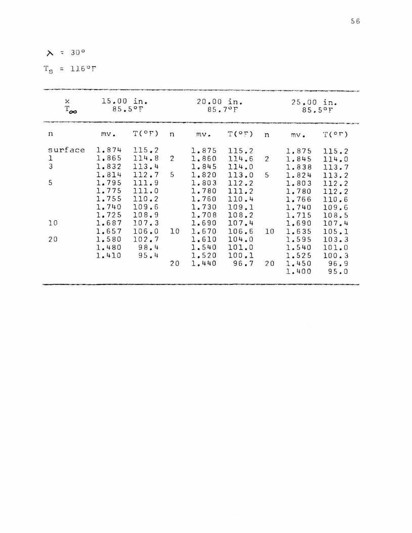
)'.. -:: 30°
Ts :::. 116°F
---·· ~- ___ ,.. ._...,._~_ ....._.-.-~. - ....... - ·----·----------..... ---~
X 15.00 ln. 20.00 ln. 25.00 in. T
00 85.5°f 85.7°F 85.5°'F'
·---... -· ----n mv. T( 0 'F') n mv. T(O'C') n mv . T (Of")
surface 1.874 115.2 1.875 115.2 1.875 115.2 1 1.865 114.8 2 1.860 114.6 2 1.845 114.0 3 1.832 113.4 1.845 114.0 1.838 113.7
1.814 112.7 5 1.820 113.0 5 1.824 113.2 5 1.795 111.9 1.803 112.2 1.803 112.2
1.775 111.0 1.780 111.2 1.780 112. 2 1.755 110.2 1.760 110.4 1.766 110.6 1.740 109.6 1.730 109.1 1.740 109. 6 l. 725 108.9 1.708 108.2 1.715 10 8 .5
10 1.687 107.3 1.690 107.4 1.690 107.4 1.657 106 .0 10 1. 6 70 106.6 10 1.635 105.1
20 1.580 102.7 1.610 104.0 1.595 10 3.3 1. 480 98.4 1.540 101.0 1.540 101. 0 1. 410 9 5 o L~ 1.520 100.1 1.525 100. 3
20 1.440 9 6 .7 20 1.450 96. 9 1.400 95.0

57
~ :. JO<'
X 0.25 ~n. o.so l.n. 1.00 1.n. Tot sgor 89°f' ego:
n mv. T(Of') n mv. T(O:r) n mv .. T(Or)
surface 3.030 162.9 3.045 163.5 3.060 164.1 1 2.980 160.9 1 3.000 161.7 1 3,.015 162.3
2.935 159.1 2.937 159.2 2.966 160.3 2.890 157.2 2.890 157.2 2.930 159.1 2.830 155.1 2.859 156.0 2.910 158.1 2.774 152.6 2.820 154.4 2.882 157.1 2.757 151.9 2.785 153.0 2 2.835 155.0
2 2.720 150.4 2 2.771 152.4 2.789 153.2 2.683 148.8 2.718 150.3 2.740 151.2 2.624 146.4 2.649 147.4 2.714 150.1 2.575 144.4 2.590 145.0 2.687 149.0 2.525 142.4 2.544 143.2 5 2.573 144. 3
5 2.390 136.8 5 2.448 139.2 2.450 139.0 2.298 133.0:': 2 .. 340 134.8 2.310 133.5 2.190 128.5 2.238 130.5 2.225 130.0 2.090 124.2 2.132 126.o:': 2.125 125. 2 1.985 119.9 2.040 122.2 2.020 121.4 1.900 116.3 1.940 118.0 10 1.830 113.4
10 1.740 109.6 1.845 114.0 1.690 10 7. 4 1.570 102.3 10 1.650 105.7 1.597 103.4 1.460 97.6 1.510 99.7 1.527 100.4 1.390 94.5 1.448 97.0 1.471 98.0
20 1.324 91.7 1.400 95.0 1 .. 400 95.0 1.305 90.9 1.365 93.4 1.325 91.7
20 1.320 1 .. 320 91 .6
* See foot n ote at the bottom of Pare 52.
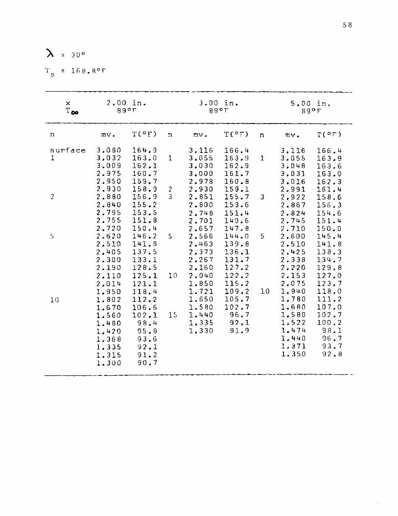
58
A = 30°
T = 168.B 0 r s
··-X 2.00 in. 3.00 in. 5.00 1n. Too sgor 89or 89°f'
n mv. T(°F) n mv. T(Of') n mv. T(Of')
surface 3.080 164.9 3.116 166.4 3.116 166.4 1 3.032 163 .. 0 1 3.055 163.9 1 3 .. 055 163.9
3.009 162 .. 1 3.030 162 .. 9 3.048 163.6 2 .. 975 160.7 3.000 161.7 3 .. 031 163.0 2.,950 159 .. 7 2.978 160.8 3.016 162.3 2.930 158.9 2 2 .. 930 159.1 2.991 161.4
2 2.880 156.9 3 2 .. 851 155.7 3 2.922 158.6 2 .. 840 155 .. 2 2.800 153 .. 6 2.867 156 .. 3 2.795 153.5 2.748 151.4 2.824 154.6 2.755 151 .. 8 2.701 149.6 2 .. 745 151 .. 4 2.720 150.4 2.657 147.8 2.710 150.0 2.620 146.2 5 2.566 144 .. 0 5 2 .. 600 145.4 2.510 141 .. 8 2 .. 463 139.8 2.510 141.8 2.405 137 .. 5 2 .. 373 136 .. 1 2.425 138.3 2 .. 300 133.1 2 .. 267 131 .. 7 2.338 134.7 2.190 128.5 2 .. 160 127 .. 2 2 .. 220 129.8 2.110 125.1 10 2 .. 040 122.2 2.153 127.0 2 .. 014 121 .. 1 1.850 115.2 2.075 123.7 1.950 118 .. 4 1.721 109.2 10 1.940 118.0
10 1 .. 802 112 .. 2 1.650 105.7 1.780 111.2 1 .. 670 106.6 1 .. 580 102.7 1. 6 80 107.0 1.560 102 .. 1 15 1,440 96.7 1. 5 80 102.7 1 .. 480 98.4 1.335 92.1 1.522 100. 2 1.420 95.8 1 .. 330 91.9 1 .. 474 98.1 1 .. 368 93.6 1.440 96.7 1.335 92.1 1.371 93,.7 1.315 91.2 1.350 92.8 1.300 90.7

59
>. = 30°
Ts = 168.8°F . . . . . ' .... . ..
X 8.00 . ~n. 11.00. in. 12.00 in.
TCIII 89or 8S°F 87.5°F . . ...... ' . , . . .. . , . ' ..
n mv. T(°F) n mv. T(°F) n mv. T( °F')
surface 3.125 16&.7 3.125 166.7 3.125 166.7 1 3.100 165.7 1 3 .• 100 165.7 1 3.100 165.7
3. 0 76. 164.8 3.076 164.8 3.076 164.8 3. 0.46 163.3 3. (150 1fil.8 3.050 163.8
2 2.988 161.2 3. 0.25· 162.8 3.030 162.9 2.935. 159..1 2 2.973 160,4 2 2.999 161.7 2.890 15-7.2 2.945 159.5 3 2.948 159.6 2.860 156.0 4 2.877 156.7 2.900 158.3
4 2.805 153.8 2.816 154-.2 2. 85 3 155.8 2.740 151.2 2.760 152.0 2.790 153.2 2.665 148.1 2.7(}0 149.6 2.760 152.0 2. 5·9.0 145..0 5 2.630 146.7 5 2.640 147.1
5 2.500. 141.4 2.550 143 .• 4 2.516 142.0 2.420 138.1 2. 48.0 140.6 2.400 137.2 2.350 135.2 2.420 138.1 2.305 133.3 2.280 132.2 2. 3 40. 134.8 2.190 128.4 2.208 129.2 2.270 131.8 2.105 124.9 2.130 126.0 2.180 l28.l 2.036 122.0 2.050 122.6 2.110 125.1 1.975 119.5 1.985 120.1 1.985 122.1 10 1.8'+0 114.2
10 1.870 115.0 10 1.925 117.4 1.755 110.2 1.760 110.4 1. 80.0 112.1 1.670 106.6 1.650 105.7 1.720 108.7 1.610 104.0 1.580 102.7 1.610 104.0. 1.550 101.4 1.530 100.6 1.550 101.4 20 1.440 96.7 1.480 98.4 l.S.OO 99. 2. 1.350 93.2 1.455 97.3 1.455 97.3 10 1.345 92.5 1.380 94.1 1.41(), g,s. 4 1.370 93.7 1.378 9.4. 0
1.370 93.7 . . . . ' ' . ... ' . ...... . . . ' . , .......... o o ' ' ' ' o o ' I ll 0 '
' I o o •
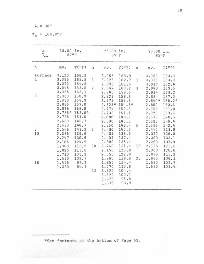
60
A. = 30°
X 15,00 in. 25,00 in. 26.50 in. Too 87°F 85°F 85°F
n mv. T(°F) n mv. T(°F) n mv. T(°F)
surface 3.120 166.2 3,055 163,9 3,055 163.9 1 3,095 165,5 1 3.025 162.7 1 3,035 163.9
3,070 164,5 2.995 161.5 3,017 162,4 3.045 16 3. 5 2 2.964 160.2 3 2,940 159.5 3,035 163.1 2.945 159.5 2.914 158.2
3 2.980 160,9 2.923 158.6 2.884 157.0 2.930 158.9 2.875 156,6 2.840* 155. 2~'; 2.885 157.0 2.825* 154.6)': 2. 80 0 153.6 2,835 155.0 2.774 152.6 2.755 151.8 2.785'': 153.0ic 2.738 151.1 2. 72 5 150.6 2.735 151.0 2,680 148,7 2.677 148,6 2.680 148.7 2,590 145.0 2.625 146.4 2.630 146.7 2.550 143,4 5 2,525 142.4
5 2.545 143.2 5 2. 480 140.6 2.440 138.9 10 2,385 136.6 2.435 138.6 2. 370 136.0
2.247 130,9 2,407 137.4 2.300 133.1 2.105 124.9 2.380 136.4 2,260 131.4 1.960 118.9 10 2.260 1_31. 4 10 2.125 125.8 1,825 113.6 2.150 126.8 2.000 120,6 1.710 10 8. 2 2,055 122.8 1.875 115.2 1. 5 80 102.7 1.960 118.9 20 1.660 106.1
15 1.475 98,2 1.855 114.4 1.580 102.7 1. 380 94.1 1.770 110.8 1,550 101.4
15 1.620 104.4 1.520 100.1 1.420 95.8 1.375 93,9
*See footnote at the bottom of Page 52.
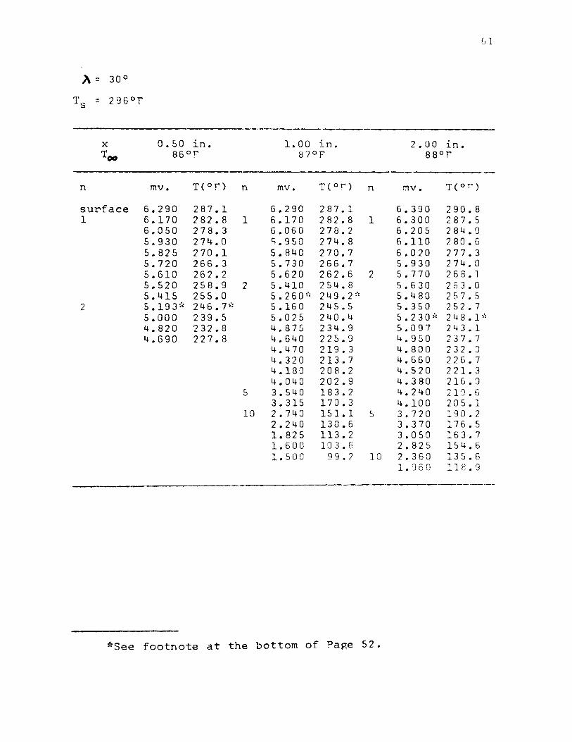
X o.so in. l. 00 1.n. 2.00 in. Too 86°F' 87°F 88°T"'
n mv. T(°F) n mv. T(Or') n mv. T( 0 f)
surface 6.290 287.1 6.290 287.1 6.390 290.8 1 6.170 282.8 1 6.170 282.8 1 6.300 287.5
6.050 278.3 6.060 278.2 6.205 284.0 5.930 274.0 s.950 274.8 6.110 280.6 5.825 270.1 5.840 270.7 6,020 277.3 5.720 266.3 5.730 266.7 5.930 274.0 5.610 262.2 5.620 262.6 2 5.770 268.1 5.520 258.9 2 5.410 254.8 5.630 263.0 5.415 255.0 5.2so~·, 249.2~·, 5.480 257.5
2 5.193~·, 246.7"' 5.160 245.5 5.350 252.7 5.000 239.5 5.025 240.4 5.23o~·, 248.1•'c 4.820 232.8 4.875 234.9 5.097 243.1 4.690 227.8 4.640 225.9 4.950 237.7
4.470 219.3 4.800 232.0 4.320 213.7 4.660 226.7 4.180 208.2 4.520 221.3 4.040 202.9 4.380 216.0
5 3.540 183.2 4.240 210. 6 3.315 170.3 4.100 205.1
10 2.740 151.1 5 3.720 190.2 2.240 130.6 3.370 176.5 1.825 113.2 3.050 163.7 1.600 103.6 2.825 154.6 1.500 99.2 10 2.360 135.6
1. 960 118.9
*See footnote at the bottom of Page 52.

62
X 4.00 1n .. 8.00 ln. 10.00 in. Too 90°f 88°F 87°f
n mv. T( 0 f) n mv. T( 0 f) n mv,. T(°F)
surface 6,.440 292 .. 6 6,.480 294 .. 0 6.550 296.5 1 6.360 289.7 1 6.410 291.5 1 6.480 294 .. 0
6,.280 286,.8 6.355 289.4 6.415 291.7 6.200 283.9 6,.290 287.1 6.355 289.1 6.120 280.9 6.230 285.1 6.300 287.5 6,.040 278.0 2 6.117 280.8 6.250 285.7
2 5.820 270.0 6.030 277.7 2 6.140 281.7 5.683 264.9 3 5 .. 880 272.2 6.025 277.5 5.565 260.5 5.725 266.4 5.975 275.7 5.450 256.3 5.530 259.2 5.810 269.2 5.340 253.3 5.345 252.4 5 5,.600 262.1 5,.230 248.1 5.280 250.0 5.367 253.2 5.124 244.1 5 4,.963 238.1 5. 0 3 8 240.9
5 4.720 1: 229. p': 4,.620;': 225.1;': 4.660 1' 226.7;'; 4,.420 217.5 4.310 213.3 4.400 216.7
1 0 3.600 185.7 4.020 202 .. 1 4.175 208.0 3.725 190.5 3,.990 200.9 3 .. 468 180.4 3,.660 18 8 . 0 3.279 172.9 3.375 17 6 .7 3.022 162.9 3.270 172.5
10 2 .. 645 147.3 10 2.920 158.5 2.300 133.1 2.525 142.4
2.260 131.4 2.025 1 21. 6
*See footnote at the bottom of Page 52.

63
X 15.00 . J.n. 20..00 in. 25,00 • J..n • . Too 87°F 86°F 86°F
n mv. T(°F) n mv. T(°F) n · mv. T(°F)
surface 6,550 296.5 6,550 296.5 6.~so 292,9 1 6.~90 29~.3 1 6.500 29~.7 1
6.~30 292.2 6,450 292.9 6.375 290.2 6.400 2Rl.1 1/~ 6.290 287.1 6,320 288.2 6.355 289.4 6.270* 286.~*
2 6.225 284.~ 2 6.250* 285.7* 6,240 285.3 6.120 280.9 6.150 278.3 6.223 28~.7 6.070* 279;1* 5 5.900 272.9 6.223 284.7
5 5,840 270.8 5.660 264.1 1 6.16 5 282.6 5.535 259.4 5.440 255.9 6.12 5 281.1 5,375 253.5 5.220 247.8 6.000 276.6 5.170 245.9 4.975 238.6 4.780 230.0 4,600 224.3 4.300 212.9 3,925 198.4
10 3,570 184.4 3.120 166.5 2.880. 156,9 2,600 145.4
*See f oot note at the bottom of Page 52.

)\ : JOO
T9 = 407°F
n
1. ao in. 85°F
mv. T(9F) n
surface 9 , 260 391,0 1 9 , 150 387,3 1
9 • 0 5 o. 3 8 3 • 9 8,950- ' 380,5 8,840 376.8
2 8. 630 36.9 .• 6 8, 430* 362.7* 8.230 255,8 8,030 3'l8.8 7,830 341.9 7 . 630 334.9 7. 550 332.1
5 7,050 314.4 6,500 294,8 6,090 2.79,9 5.580 261.1 s. ooo 239,4 4,570 223.2 4. o. 40 2 0 2. 9 3,540 183.2
3 •. ao in. 85QF
mv. T(°F)
9,330 393,4 9. 24-0. 390,,4 9 .• 150 387,3 9. 0.60. 384.3 8,970* 381.2• a·. 870 377.8
n
1
2
5
•see footnote at the bottom of Page 52.
7.aa in. 85°F
mv. T(°F)
9,&50 404,2 9 .• 540 400,5 9,430 396.8 9.320 393.1 9,200 389.0 9,110 386.0 8,935 380.0
64
8,730• 373.0• 8.525 366.0 8,330 359,3 8,130 352.3 7.730 338.3 7.137 3.17. 5 6,635 299.5 6.200 283.9 5.825 270.1 5.370 253.3

65
X 9.00 in. 11 .. 00 in. 15.00 in. T - 85°F 85°F 85°F
n mv. T(°F) n mv. T(°F) n mv. T(°F)
surface 9.720 406.7 9 .. 720 406.7 9.720 406.7 1 9.600 40 2. 5 1 9.,600 402.5 1 9.610 402.9
9.485 398.7 9.485 398.5 9.510 399 .. 5 2 9.280 391.8 2 9.280 391,.8 9 .. 415 396.3
9.065 384.4 9.070 384.6 2 9.225 389.1 8.860 377.5 8.870 377.8 9.050 384.0 8.680{: 371.3{: 8,.870 377.8 8.880 378.1
5 8.280 357 5 8.240 365.1 8.725 372.9 7.670 336 7.745 339.0 5 8.250 356.5 7.290 323 7.280 322.4 7.800 341.1 6.680 301 6.850* 307.31: 7. 380 1' 326.1 1' 6,.365 290 6.430 292 6.,900 309.9 5.960 275 10 5.530 259 6.430 292.1 5.364 253 4.,460 219 10 5.570 260.8 5.000 240 3.850 195 5.050 241.3 4,570 223 3.120 166 4.250 211.0 4.030 203 20 2.650 148 3.730 190.8
10 3.220 171 2.800 154 2.400 137 1.920 117
*See footnote at the bottom of Page 52.

66
)\ : 45°
Ts = 165.5°F . . . ' . ' . ' . ' ... ....
X 0.50 • 1.00 in. 2 .ao . l.n. l.n. TOf 85°!' 85°F 84.5°F
' ' .. ' .. ' . . ' . .. . . . ' ' . . . ' ' . .. . . . ' . ...... '
n mv . T(°F) n mv. T(O F) n mv. T(°F)
surface 2.850 155.7 2. 9.10 158.1 2.970 160.5 2.825 154.6 2 2.859 156.0 2 2.920 158.5
2 2.775 152.6 2.803 153.7 2.870 156.4 2.710 150.0 2.724 150 .• 5 2.823 154,5 2. 650. 147,5 2.690 149.1 2.800 153.6 2.610 145.8 2. 6.55 147.7 2.770 152.4 2.570 144.2 5 2.525 142.4 5 2.656 147.7
5 2.438* 138.8~': 2.450 139.3 2.570 144.2 2.250 131.0 2.390 136.8 2.490 141.0 2.125 125.8 2.180* 128.1* 2,377 136.3 1. 9·80 119.7 2. 0.6.0 123.0 2.200 128.9 1.760 110.4 1.940 118.0 2.107* 125.0* 1.620 104.4 1.825 113.2 2.030 121.8
1.710 10 8. 2 1.965 119.1 1.594 10 3. 3 1.870 115.0
10 1.470 98.0 1. 770 111.2 1.460 97.6 1.700 107.8 1.460 97.0 10 1.610 104.0
1. 510 99.7 1.410 95.4 1.320 91.5 1.290 90.2 1.270 89.7 . . . . . . ' . . . . ......
*See f ootnote at the bottom of Pa ge 52.
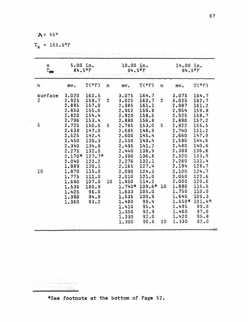
67
}\ = 45°
Ts = 165.5°F
X 5.o.a in. lO..Qil in. 14. ClO in. Too 84.59F 84 •. 59 r 84.5°F
' ' ' ' . . . . '.· . ' .. ' . . ' .. ' . .. ' . .
n mv. T(°F) n mv. T(9F) n mv. T(°F)
surface 3,020 162.5 3.075 164.7 3.075 164.7 2 2.~25 158.7 2 3.025 162.7 2 3.025 162.7
2.885. 157.0 2. 9.8 5 161.1 2,987 161.2 2.850 155. 6. 2.9.S2 159.8 2.954 159.8 2.820 154.4 2. 920. 158.5 2.925 158.7 2.796 153.4 2.880 156.8 2.89.0 157.2
5 2.725 150.6 5 2.785 153.0 5 2.822 155.5 2.638 147.0 2.685 148.9 2.740 151.2 2.525 142.4 2. 6.0 0 145..4 2.660 147.9 2. 45.0 139.3 2.550 14l.4 2.580 144.6 2.340 134.8 2.49.5 141.2 2.480 140.6 2.275 132 .• 0 2. 440. 138.9 2.388 136.6 2.170* 127.7* 2.390 136 .• 8 2.320 13 3. 9 2.040 122.2 2.276 132.1 2.260 131.4 1.989 120.1 2.165 127.4 2.194 128.7
10 1.870 115.0. 2.090 124.3 2.100 124.7 1.775 111.0 2.010 121.0 2.050 122.6 ·1. 680. 1a 7. o. 10 ]..850 114.2 2.000 120.6 1.53-5 J.O,Q.. 9. 1.740* 109.6* 10 1.880 115.5 1.425 96 .• 0 1.633 105.a 1.750 110.0 1.390 94.0 1.535 1GQ.9 1.640 105.3 1. 360 93.2 1.480 98.4 1.550* 101.4*
1.410 9.5. 4 1.495 99.0 1.350 92.9 1.460 97.6
. 1. 330 92.0 1.420 95.8 1.300 90.6 20 1.330 92.0
*See footnote at the bottom of Page 52.

G8
*See footnote at the bottom of Page 52.
**The ambient air temnerature fluctuated noticeablv.
69
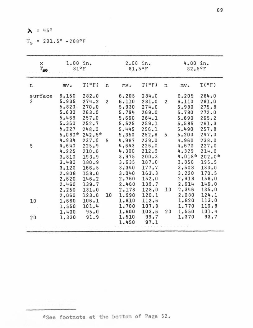
)\ = 45°
T5 = 291.5° -288°F
X 1.00 in. 2.00 in. 4.00 . J.n. Too 81°F 81.5°F 82.5°F
n mv. T(°F) n mv. T(°F) n mv. T(°F)
surface 6.150 282.0 6.205 284,0 6,205 284.0 2 5.935 274.2 2 6,.110 281.0 2 6.110 281.0
5. 820 . 270.0 5,930 274.0 5,980 275.8 5. 6 30 263.0 5,794 269,0 5.780 272.0 5.469 257,0 5.660 264.1 5.690 265.2 5,350 252.7 5.525 259.1 5.585 261.3 5.227 248.0 5.445 256.1 5,490 257.8 s. 0 80 ''c 242.5* 5,350 252,6 5 5.200 247.0 4,934 237.0 5 4,987 239.0 4.960 238.0
5 4.640 225.9 4.643 226.0 4,670 227.0 4.225 210.0 4.300 212.9 4,329 214.0 3.810 193.9 3.975 200.3 4.018* 202.0* ·3.480 180.9 3 .635 187.0 3.850 195.5 3.120 166.5 3.340 177.7 3,508 183.0 2.908 158.0 3,040 163.3 3.220 170.5 2.620 146.2 2.760 152.0 2.918 158.0 2.460 139.7 2.460 139.7 2.614 146.0 2.250 131.0 2.178 12.8.0 10 2.346 135.0 2.060 123.0 10 1.990 12.0.1 2.080 124.1
10 1.660 106.1 1.8.10 112..6 1.820 113.0 1,550 101.4 1.700 107.8 1.770 110.8 1.400 95.0 1.600 103.6 20 1.550 101.4
20 1.330 91.9 1. 510 9:9.7 1.370 93.7 1.450 97.1
. ' ... '
*See footnote at the bottom of Page 52 .

70
)\ :: 45°
Ts :: 291 .. 5° to 288°F
---·- -·---X a.oo J.n .. 12.00 in. 15 .. 00 J.n. Ts Too 83°F 84°F 85°T'
---n mv .. T(°F) n mv. T(OT') n mv. T( 0 r)
surface 6.260 286.0 6.,375 290.2 6.400 291.1 2 615.0 2 82 8 0 2 6.225 284.8 2 6.310 287.9
6.020 277.3 6.140 281.7 6.215 284.4 5.920 273.,7 6.040 278.0 6.135 281.5 5.820 270.0 5.930 274.0 6.050 278.4 5.725 266.4 5.850 271.1 5.970 275.5 5.640 263.,3 5.800 269.3 5 5.745 266.8
5 5.352 252 .. 7 5 5.577 261.0 5.457 256.5 5.045 241.2 5. 32 4 251.7 5.220 247.8 4.820 232.7 5.035 240.8 4.925 237.3 4.540 222.1 4.810 232.3 4.720 229.1 4.277-f; 212.0;'; 4.570 223 .. 1 4.410 217.1 4.018 202.0 10 4.070;'; 204.0;'; 4.260 211.3 3.740 191.1 3.680 188.8 3.993 201.0 3.485 181.1 3. 30 0 173.7 3.550;'; 183.7~':
10 3.150 167.7 2.890 157.2 3.240 171.3 2.825 154.6 2.589 145.0 10 2.910 158.0 2.443 139.0 2.250 131.0 2.640 147.1 ·2 .17 8 128.0 1.916 117.0 2.460 139.7 1.880 115.5 1.770 110. 8 2.250 131.8 1.625 104.7 1.680 107.0 1.930 117.6 1.540 101.0 1.540 101.0 1.810 112.6 1.460 97.6 20 1.400 95.0 1.615 104.2
20 1.378 94.0 1.360 93.2
*See footnote at the bottom of Pap,e 52.
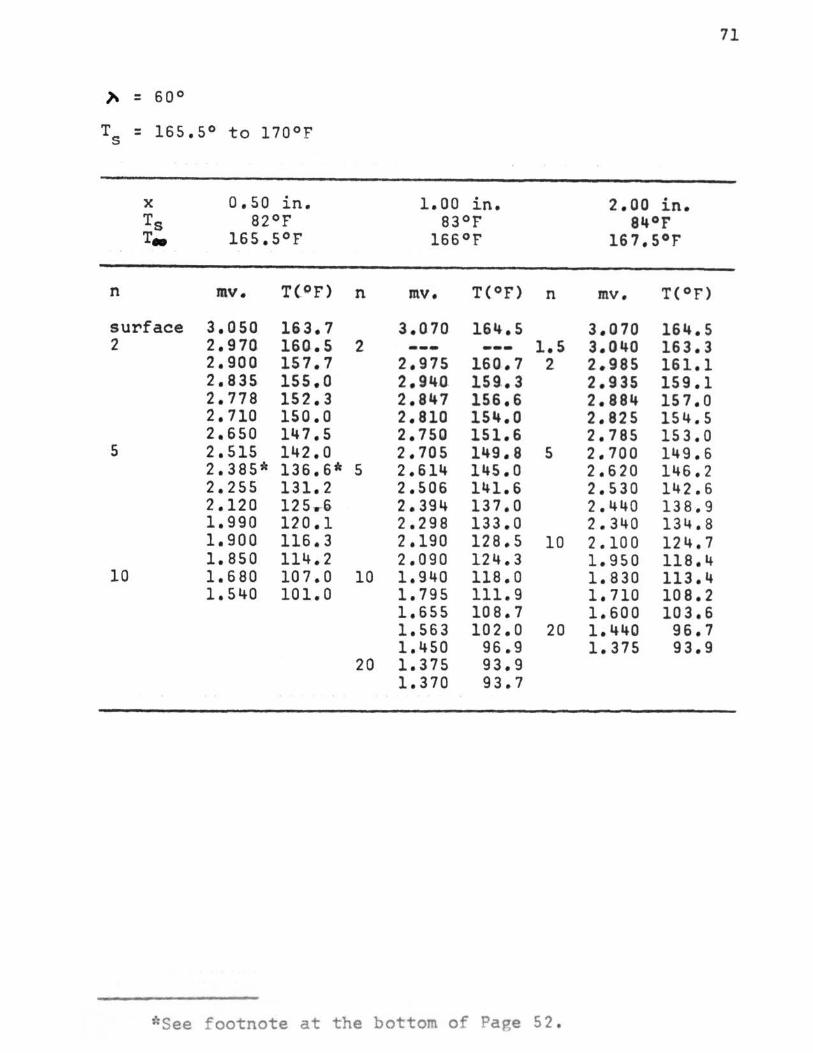
71
" = 60°
T5 = 165.5° to 11oor
X 0.50 in. 1. 00 in. 2.00 in. Ts 82°F 83°F 84°F T• 165.5°F 166°F 167.5°F
n mv. T(OF) n mv. T(°F) n mv. T(°F)
surface 3.050 163.7 3.070 164.5 3.070 164.5 2 2.970 160.5 2 --- --- 1.5 3.040 163.3
2.900 157.7 2.975 160.7 2 2.985 161.1 2.835 155.0 2. 94.Q 159..3 2.935 159.1 2.778 152.3 2.847 156.6 2.884 157 .a 2.710 150.0 2.810 154.0 2.825 154.5 2.650 147.5 2.750 151.6 2.785 153.0
5 2.515 142.0 2.705 149.8 5 2.700 149.6 2.385* 136.6* 5 2.614 145.0 2.620 146.2 2.255 131.2 2.506 141.6 2.530 142.6 2.120 125..-6 2.394 137.0 2.440 138.9 1.990 120.1 2.298 133.0 2.340 134.8 1.900 116.3 2.190 128.5 10 2.100 124.7 1.850 114.2 2.090 124.3 1.950 118.4
10 1. 6 80 107.0 10 1.940 118.0 1.830 113.4 1.540 101.0 1.795 111.9 1. 710 108.2
1.655 108.7 1.600 103.6 1.563 102.0 20 1.440 96.7 1.450 96.9 1.375 93.9
20 1.375 93.9 1.370 93.7
*See footnote at the bottom of Pa e 52.

72
X 4.00 in. a.oo in. 12.00 in. Ts 85°F 87°F 87°F' Too 168°F' 170°f' 170°f'
n mv .. T(°F) n mv .. T(°F) n mv. T(°F)
surface 3.075 164.7 3.165 168.4 3.180 168.9 2 3.025 162.7 2 3 .. 085 164.5 1 .. 5 3.150 167.,7 3. 3 2.940 159.3 3.040 163.3 3 3 .. o 70 164.S
2.870 156.4 5 2.960 160.1 3,.020 162.5 2.800 153.6 2.882 156.9 2.975 160.6
5 2.755 151.8 2.810 154.0 5 2.903 157 .. 8 2 .. 650 147.5 2.711 150.0 2.840 155.2 2.560 143,.8 2 .. 635 146 .. 9 2.780 152.8 2.490 141.0 2.560 143.8 2.700 149.6 2.410 137.7 2.480 140 .. 6 2.620 146.3
10 2 .. 260~'= 131.4='' 2.420 13 8 .. 1 2.540 143.0 2.108 125.0 2.350 135.2 2.470 140.1 1.970 119 .. 3 2.280 132.0 2.400 137.2 1.850 114.2 10 2.120 125.6 10 2 .. 240 130.6 1,.680 107.0 1.990 120.1 2.130 126,0
20 1,.475 98.2 1.850 114.2 2.000 120.6 1.378 94 .. 0 1.760 110.4 1.920 117.2 1.300 90.6 1.680 107.0 1.810 112.6
1.600 103.6 1.725 108.9 1.520 100.1 1.645 105.5
20 1.450 97.1 20 1.520 100. 1 1.420 95.8 1.450 97.1
1.370 93.7
*See footnote at the bottom of Page 52.

73
,.. = 60°
T5 = 165.5° to 170°F
X 16.00 in. 2o.o.a in. 2 5 • 0.0. in • Ts 870F 87QF 88°F T., 170°F 170°F 170°F
n mv. T (.QF) n mv. T(°F) n mv. T(°F)
surface 3.175 168.7 3.175 168.7 3.175 168.7 3 3.120 166.5 3 3.127 166.8 3 3.130 167.0
3.070 1&4.5 3.083 1ss.a 3.085 165.1 5 3.018 162.4 3.04(1 1Gl.3 3. 040 163.3
2.952 159.8 5 2.940 160.5 10 2.920 158.5 2.840 155.2 2. 9.00 157.8 2.785 153.0 2.765 152.2 2.835 155.0. 2. 680 148.7 2.680 148.7 2.770 15.2.4 2.520 142.2 2.605 145.6 2.700 149..6 2.420 138.1 2.510 141.8 2.630 146.7 2.310 133.6 2.425 138.3 2 .• 560 143.9 2.185 12 8. 3 2.360 135.6 2.500 141.4 20 2.000 120.6
10 2.230 130..2 2.445 139.1 1.820 113.0 2.100 124.7 10 2.290 132.7 1.720 10 8. 7 2.ao.a 120.6 2.175 123.7 1.880. 115.5 2.075 123.7
20 1.725 108.9 2 .• 000 120.6 1.620 10.4.4 1. 9.10 .116. 8 1.470. 98.1 20 1.730 109.1
1. sao. 103.6. ~ .. sao 9.9. .. 2

)\ = 60°
T8 : 294°F
X
T.,_
n
surface 2
5
10
o.so in. 86°F
mv. T(°F)
6.170 282.8 6.10 277.1 5.845 270.9 5.680 264.8 5.520* 258.9~' 5.350 252.6 5.200 247.0 4.850 233.9 4.450 218.7 4.125 206.1 3.680 188.8 3.132 167.0
1.00 in. 85 .. 5°F
n mv. T(°F) n
6.170 282.8 2 6.030 277.7 2
5.905 273.1 5.775 268.3 5.640 263.3 5.515 258.7 5.375;'; 253.5* 5.250 248.9
5 4.880 235.0 5 4.550 222.6 4.250 211.0 4.000 201.3
10
*See f ootnote a t the bottom of Page 5 2.
74
2 .. 00 in. 85°F
mv. T(° F )
6.170 282. 8 6.050 278.3 5.932 274.1 5.815 269.8 5.700 265. 6 5.585 261.3 5.470 257.0 5.350 25 2.6 5.040''' 2 41. 0 :': 4.740 229. 6 4.440 218. 2 4.150 2 4 5. l 3.850 195. !4 3.350 17 5 . 8 2.910 158. 1

75
X 4.00 in. 8.00 in. 12. 0.0 in. r.. 85°F 85°F 8~.5°F
n mv. T(°F) n mv. T(°F) n mv. T{°F)
surfaae 6.270 286.~ 6.400 291.1 6.470 293.6 2 6.120 281.1 2 6.300 287.5 2 6. 380 290.4
s.ooo 276.6 6.210 28~.2 6.287 287.0 s .-gao· 272.9 6.090 279.9 6.180 283.1 5.770 268.1 6.008 276.9 6.100 280.2 5.670 264.5 5.895 272.7 6.010 277.1 5.570 260.8 5.820 270.0 5.920 273.6 5.a.so 256.7 5.725 266.5 5.825 270.1
5 5.160 2~5.5 5 5.~60 256.6 5 5.590 261.5 ~.860 234.2 5.220 247.8 5.440 256.1 4.570* 223.2* 4.975 238.6 5.215 2~7.6 4.280 212.1 4.7~0 229.~6 4.940 237.2 4.000 201.3 4.460 219.0 4.725 228.9 3.740 191.1 4.230 210.2 4.500 220.6 3.480 181.1 3. 9.80 2.00. 5 4.300 212.9 3.240 171.3 3.720 190.3 4.060 203.6 3.075 164.7 3.S59 184.0 3.820 193.7 2.850 155.6 3.4Cl7 178.0 3.590 185.2 2.570 144.2 10 2. 9.5.0. 159.7 10 3.210 170.1
10 2.270 131.8 2.6QO 145.4 2.910 158.1 2.025 111.6 2.275 232.0 2.610 145.8 1.780 111.2 2.060 123.0 2.330 133.9 1.700 107.8 1.860 114.6 2.170 12 7. 7 1.700 107.8 1.725 108.9 20 1.720 108.7
20 1.570 102.3 1•525 100.3 1.470 98.0
*See footnote at the bottom of Page 92.
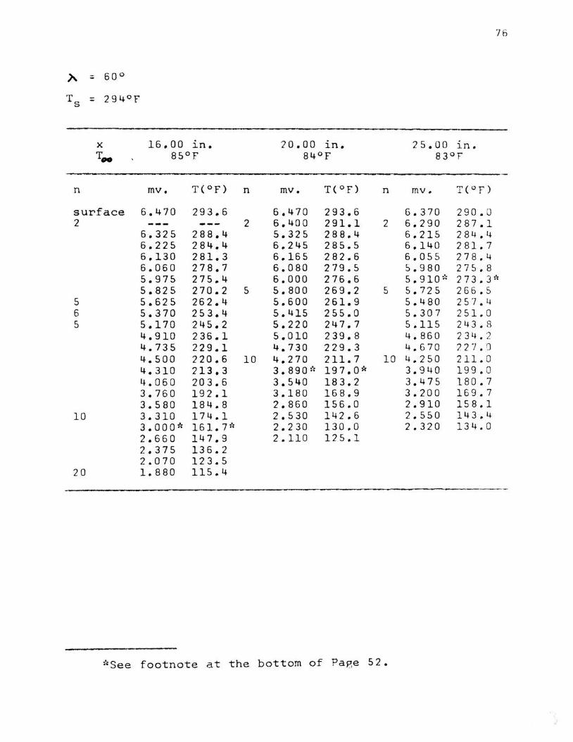
76
X 16,.00 l.n. 20.00 l.n. 25.00 1n. T.,. 85°F 84°F 83°F
n mv. T(°F) n mv. T( ° F) n mv. T( ° F)
surface 6.470 293.6 6,470 293.6 6.370 290.0 2 2 6.400 291.1 2 6.290 287.1
6.325 288.4 5.325 288.4 6.215 284.4 6.225 284.4 6.245 285.5 6.140 281.7 6,.130 281.3 6.165 282.6 6.05 5 278 . 4 6.060 278.7 6.080 279.5 5.980 275.8 5.975 275.4 6.000 276.6 5.910~= 273.3~~
5.825 270.,2 5 5.800 269.2 5 5.725 266.5 5 5.625 262.4 5.600 261.9 5.480 257. 4 6 5.370 253.4 5.415 255.0 5.307 251 . 0 5 5.170 245.2 5.220 247.7 5.115 243 . 8
4. 910 236.1 5.010 239.8 4.860 234 . 2 4.735 229.1 4.730 229.3 4.670 7.27. 0 4.500 220.6 10 4.270 211.7 10 4.250 211. 0 4.310 213.3 3.ago~·= 197.0* 3.940 199. 0 4.060 203.6 3.540 183.2 3.475 180. 7 3.760 192.1 3.180 168.9 3.200 16 9 . 7 3.580 184.8 2.860 156.0 2.910 158.1
10 3.310 174.1 2.530 142.6 2 .550 143.4 3.000* 161. 7~" 2.230 130.0 2.320 134.0 2.660 147.9 2.110 125.1 2.375 136.2 2.070 123.5
20 1.880 115.4
*See footnote at the bottom of Page 5 2.

77
X 0.25 in. 0.50 in. Too 88°F 88°F
n mv. T(°F) n mv. T(°F)
surface 3.085 165.1 3.085 165.1 5 2.940 159 .. 3 2 3.030 162.9
2.800 153.6 2.975 160.7 2.660 147.9 2.925 158.7 2.530 142.4 2.875 156.7 2.400 137.2 2.830 154.8 2.290 132.7 2.775 152.7
10 2.020 121.4 2.730 150.,8 1. 85o~'r 114.2 1= 2.675 148.5 1.720 108.7 5 2 .. 570;': 144.2;': 1.560 101.9 2.440 138.9 1.480 98.4 2.300 133.1 1.450 97.1 10 2.125 125.8 1.400 95.0 2.000 120.6 1.375 93.9 1.850 114.2
1.725 108.9
*See footnote at the bottom of Pape 52.

78
'A :: goo
T s = 170.5°F
-- ·-"""'""'_,.,..- -~-------
X 2 .. 50 in. 6 .. 00 1n. 13.50 in. Too 88°F 88°F' 87°1
------n mv .. T( 0 t) n mv. T(OT') n mv. TC 0 r)
surface 3.144 167 .. 5 3 .. 220 170.5 3.220 170.5 5 3.060 164,.1 5 3 .. 155 167.9 5 3.155 167.1
2.985 161.1 3,.080 164.9 3. 0 80 164 .. 9 2.900 157.7 3.005 161.9 3.005 161.9 2.815 154,.2 2.930 158.9 2,.935 159.1
20 2.500 141 .• 4 2.870 156.4 2 .. 8 70 156.4 2.250 131 .. 0 2.800 153.6 2.805 153.8 2.000 120.6 2 .. 730 150.8 2 .. 755 152 .. 2 1.800 112 .. 1 2.659 147.8 2. 710 150.0 1.660 106.4 2.595 145.2 2.670 148.3 1.520 100.1 2.530 142.4 2 .. 620 146.2
2.470 140.1 2.570 144.2 2.410 137.7 2.516 142 .. 0 2.,355 135.4 2.467 140.0 2.305 133.7 2.410 137.7 2.225 131.0 2.355 135.,4 2.200 128.9 10 2.250 131.0
20 1.910 116.8 2 .. 130 126 .. 0 1.740 109.6 2.020 121.4 1.625 104.7 1.910 116,.8
1.810 112.6 20 1.720 108.7
1.625 104.6 1,.520 100 .. 1

79
'A = goo
Ts = 289°F
·--""-- .,..,~-. . ~. _.........-----· ~·-· ......... - ......... ____ X 2.00 in. 6.00 in. 13~00 ln. T 00 87°F 87°T' 87°F
-.--....... ~~
n mv. T(°F) n mv. T(°F) n mv. T(°F)
surface 5. 9 70 275.5 6.320 288.2 6.320 288.2 2 5.850 271.1 6.220 284.6 6,200 283.8
5.740 267.0 6.060 278.8 6.100 2 82. 2 5.650 263.7 5.940 274.4 6.025 277.5 5.55o~·: 260.0* 5.875~: 212.o~·, 5,950 /74.8
5 5.320 251.5 5.760 267.8 5 5.750 267.4 5.100 243.2 5 5.510 258.5 5,540 259.6 4.940 237.2 5,320 251.S 5.325;': 251.6;': 4.740 229.6 5.120 244. 0 5,140 244.7 4.530 221.7 4.920 236.5 4.970 238,4
10 4.100 205.1 4.730 229.3 10 4.630 226.5 4.530 221.7 4.290 212.5 4.380 216.0 4.000 201.3 4.150 207.0 3.740 191.1 3,920 198.2 3.480 180.9
3.100 165.7 2.850 155.6 2.630 145.7
20 2.230 130. 1 1.740 10 9. 5 1.540 101. 0
*See footnote at the bottom of Pap.e 52.
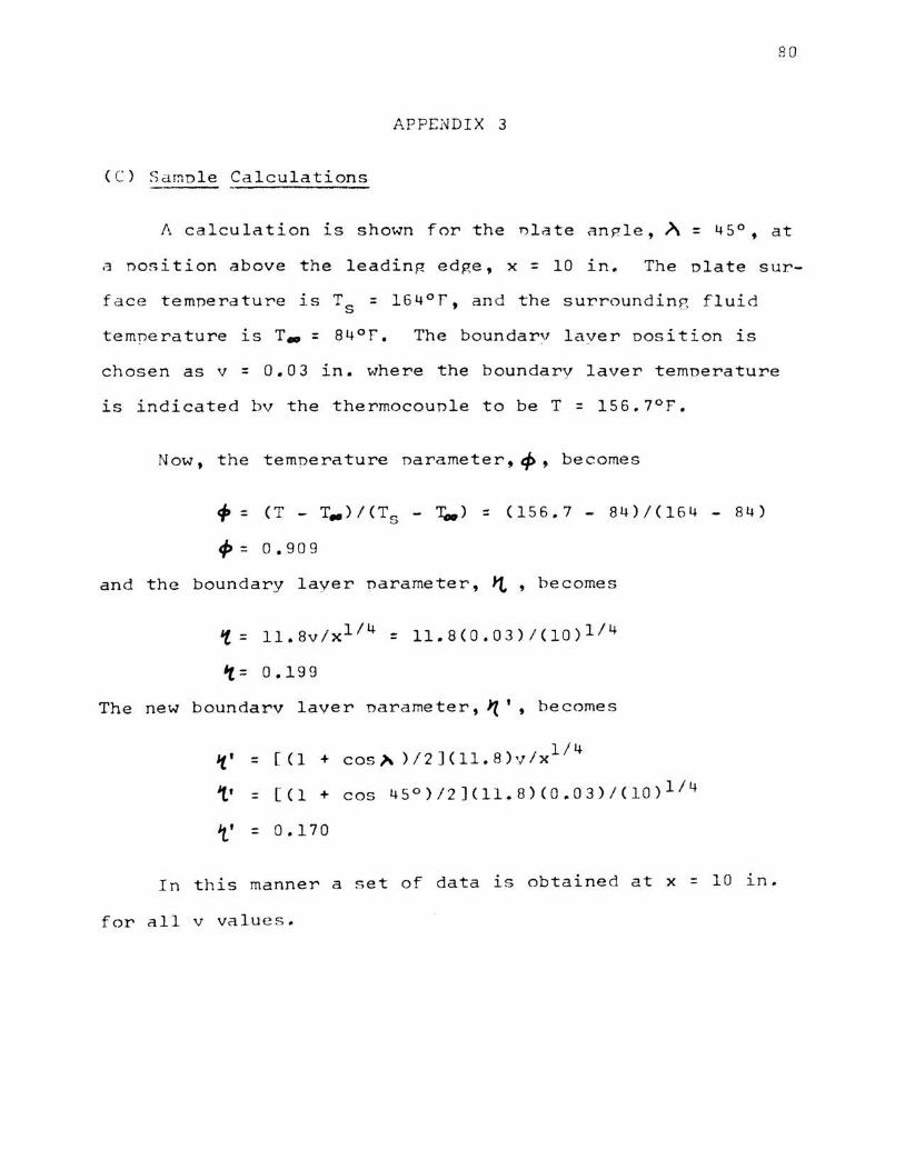
8 0
APPENDIX 3
(C) Samole Calculations
A calculation is shown for the nlate angle,~= 45° 9 at
a nosition above the leadin~ edge, x = 10 in. The nlate sur
face temperature 1s Ts = l64°F, and the surrounding fluid
temnerature is T. = 84°F. The boundarv laver oosition is
chosen as v = 0.03 in. where the boundarv laver temoerature
is indicated bv the thermocouple to be T = 156.7°F.
Now, the temoerature narameter,~, becomes
4' = ( T - T• ) I ( T s - ~ ) ::: ( 15 6 • 7 - 8 4 ) I ( 1 6 4 - 8 4 )
<P= 0.909
and the boundary layer narameter, ~ , becomes
't = 11.8v/x114 = 11.8(0.03) / (10)1/ 4
't= 0.199
The new boundarv laver narameter, J'(' , becomes
l/4 't' :: [(1 +cos~ ) /2 J<ll.B) v/x
1' = [(l + cos 45°)/2](11.8)(0.03)/(10) 114
i' = 0.170
In th is manner a set of data is obtained at x = 10 ln .
for all v values .