free and forced vibration analysis of fg beam considering ... · free and forced vibration analysis...
TRANSCRIPT
Journal of Mechanical Science and Technology 25 (1) (2011) 69~80
www.springerlink.com/content/1738-494x DOI 10.1007/s12206-010-1015-y
Free and forced vibration analysis of FG beam considering
temperature dependency of material properties† Mohammad Azadi*
Mechanical Engineering Department, Sharif University of Technology, Tehran, Iran
(Manuscript Received January 11, 2010; Revised August 6, 2010; Accepted September 13, 2010)
----------------------------------------------------------------------------------------------------------------------------------------------------------------------------------------------------------------------------------------------------------------------------------------------
Abstract This paper presents a finite element method (FEM) free and forced lateral vibration analysis of beams made of functionally graded ma-
terials (FGMs). The temperature dependency of material properties along with damping had not previously been taken into account in vibration analysis. In the present study, the material properties were assumed to be temperature-dependent, and were graded in the thick-ness direction according to a simple power law distribution of the volume fractions of the constituents. The natural frequencies were obtained for functionally graded (FG) beams with various boundary conditions. First, an FG beam was assumed to be isotropic (metal rich) and the results were compared with the analytical solution and the results for ANSYS and NASTRAN software. Finally, dynamic responses were obtained for damped and un-damped systems. Numerical results were obtained to show the influences of the temperature dependency of the materials properties, the boundary conditions, the volume fraction distribution (the index of power law, N) and the geometrical parameters.
Keywords: Free vibration; Forced vibration; Dynamic response; FEM; FG beam; Temperature dependency; Various boundary conditions; Natural fre-
quency ---------------------------------------------------------------------------------------------------------------------------------------------------------------------------------------------------------------------------------------------------------------------------------------------- 1. Introduction
Functionally graded materials (FGMs) are special compos-ite materials that have been developed for their excellent me-chanical and thermal properties. The concept of FGMs, espe-cially as relating to the thermal barrier or heat shielding utility, was proposed in 1984 by a group of material scientists, in Sendai, Japan [1-4]. Such types of inhomogeneous composite materials and systems are presently in the forefront of materi-als science research, and are receiving worldwide and increas-ing attention. The advantage of using these materials is that they are able to withstand high-temperature and stress gradient environments while maintaining their structural integrity [5, 6]. They possess properties that vary gradually and continuously in their spatial coordinates for the purposes of a required func-tion. The composition, which is varied from a ceramic-rich surface to a metal-rich surface according to a desired variation of the volume fraction of the two materials between two sur-faces, can easily be manufactured [7]. Initially, FGMs were designed as thermal barrier materials for aerospace and fusion reactors applications. Later on, they were developed for mili-
tary, automotive, biomedical application, semiconductor in-dustry, manufacturing industry and general structural elements in thermal environments.
For example, the use of functionally graded (FG) coating on structural elements in high-temperature environments can effectively help to reduce possible failures induced by thermo or combined thermo-mechanical loadings. Typical examples of those elements are movable arms, tall buildings and towers and beams used in high-performance surface and air vehicles.
The temperature dependency of material properties has not thus far been taken into account in vibration analysis. Then, one of the important problems is damping in structures sub-jected to dynamic loading, because this reduces the dynamic stress level and increases, thereby, fatigue life. One example is to control the noise, vibration and harshness (NVH) in struc-tures, such as vehicles, by a passive damping treatment. In the present study therefore, damping also was considered.
The dynamic behavior of composite beams certainly has been an active subject of research, as evidenced by the many analytical and numerical analyses published in the literature, whether based on classical Euler-Bernoulli beam theory, Ti-moshenko beam theory, or the three-dimensional theory of elasticity. Research work on FG structures in consideration of temperature dependency, however, is scarce. Contrastingly, the pure elastic mechanical behaviors of FGMs, including free
† This paper was recommended for publication in revised form by Associate EditorEung-Soo Shin
*Corresponding author. Tel.: +98 910 2107280, Fax.: +98 21 22201301 E-mail address: [email protected], [email protected]
© KSME & Springer 2011
70 M. Azadi / Journal of Mechanical Science and Technology 25 (1) (2011) 69~80
and forced vibration, stability and buckling, among others, understanding of which is of great significance to engineering design and manufacture, have also been studied by many sci-entists.
Khatua and Cheung [8-9] presented a finite element formu-lation for the analysis of multi-layer sandwich beams and plates with soft cores. In their work however, they neglected the normal stress in the core or the transverse shear in stiff layers. Rao and Nakara [10] carried out an analysis on the vibration of unsymmetrical sandwich beams and plates with viscoelastic cores. Rao [11], using an energy approach, de-rived a complete set of equations of motion and boundary conditions governing the vibration of sandwich beams. Baner-jee et al. [12] employed the dynamic stiffness method for a free vibration analysis of three-layer sandwich beams. Chak-raborty et al. [13] developed a new finite element for FG beams that proved to be fast convergent and free of shear locking. Qian and Ching [14] used a meshless method to study the free and forced vibration of an FG cantilever beam. Li-brescu et al. [15] carried out vibration and stability analysis of thin-walled FG beams in a high temperature environment. Wu et al. [16] obtained closed-form natural frequencies of a sim-ply supported FG beam with properties as polynomial func-tions of the axial coordinates. Azadi et al. [17] used a modal analysis to obtain the dynamic response of an FG beam.
FG structures in thermal environments are an attractive emerging area of research. Free lateral vibration analyses of FG beams considering temperature dependency remain rare though. The present study investigated the free lateral vibra-tion behavior of an FG beam in consideration of temperature dependency. The beam can be hinged, clamped, or free at its ends. The finite element method (FEM) and modal analysis were employed to obtain the natural frequencies and dynamic response of the FG beam. The present finite element formula-tion was used by second-order elements with 3 nodes. In this paper, first, the results for the metal-rich FG beam are com-pared analytically with the results of ANSYS and NASTRAN programs. Then, the influences of the beam geometry, the temperature change, material composition, and the end sup-port conditions on the free vibration of the FG beam are dis-cussed in detail. The results data obtained are presented in tables and figures herein. 2. FG material equations
FGMs are typically made of a mixture of ceramic and metal or a combination of different metals. The ceramic constituent, with its low thermal conductivity, imparts the high-
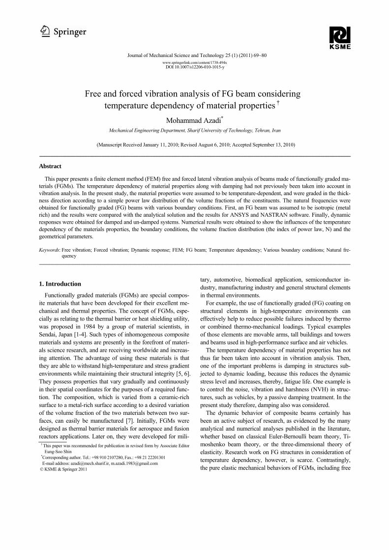
temperature resistance. The ductile metal constituent, on the other hand, prevents very sudden fractures caused by stresses due to a high-temperature gradient. Consider the FG beam shown in Fig. 1.
In the present analysis, it was assumed that the composition of the FGM stiff layer varies from the top to the bottom sur-faces, that is, the top surface (z = h/2) of the beam is ceramic-rich, whereas the bottom surface (z = -h/2) is metal-rich.
In addition, material properties were graded in the thickness direction according to the volume fraction power law distribu-tion. As FGMs are used mainly in high-temperature environ-ments, the constituent materials possess temperature-dependent properties. These properties can be expressed as follows [18]
1 2 30 1 1 2 3( 1 )P P P T PT PT PT−
−= + + + + (1) where P0, P-1, P1, P2 and P3 are constants in the cubic fit of the material properties. The material properties are expressed in this way so that the higher-order effects of the temperature on the material properties can be readily discernible.
Volume fraction is a spatial function whereas the properties of the constituents are functions of temperature. The combina-tion of these functions gives rise to the effective material properties of FGMs, which can be expressed by
( , ) ( ) ( ) ( ) ( )eff m m c cP T z P T V z P T V z= + (2)
where Peff is the effective material property of the FGMs, and Pm and Pc are the temperature-dependent properties of metal and ceramic, respectively. Vm, is the volume fraction of the metal constituent of the FGM, can be written
(3) where volume fraction index N dictates the material variation profile through the beam thickness and may be varied to ob-tain the optimum distribution of component materials (0≤N≤∞). The metal-rich FG beam defined by N is equal to zero and the ceramic-rich FG beam defined by N is equal to infinite. From the above equation, the effective Young’s modulus E and mass density ρ of an FG beam can be written
. (4a)
. (4b) In this paper, only the effective Young's modulus depends
to temperature, and the related equation is
. (5)
Fig. 1. Schematic of FG beam with used coordinates.
M. Azadi / Journal of Mechanical Science and Technology 25 (1) (2011) 69~80 71
3. Modal analysis
In this section an FEM is proposed to solve the free vibra-tion problem for non-proportionally damped Euler-Bernoulli non-homogeneous beams. In particular, two different damping models are considered: internal viscous damping, and external lumped or distributed viscous damping. 3.1 Boundary value problem [19, 20]
The partial differential equation of motion for a distributed viscously damped system can be expressed in the operator form
(6) where M, C and K are linear homogeneous differential opera-tors, and are referred to as the mass operator, damping opera-tor and stiffness operator, respectively, f is the external force density (also including all non-conservative forces other than viscous damping ones), w is the displacement in the x-direction and t is the time. Associated with differential Eq. (6), appropriate boundary conditions must be satisfied by solution w at every point of the boundary. In the special case of a Euler-Bernoulli beam in bending vibration, the mass operator and the stiffness operator consist of
(7a)
(7b) where m (x,z) is the mass per unit length of beam, V is the beam volume, k (x,z)=EI (x,z) is the bending stiffness, or flex-ural rigidity, in which E is Young’s modulus of elasticity that can be changed in two directions, x and z, and I is the area moment of inertia. The damping operator can be expressed as
(7c) which is the case of internal damping or, simply, as
(7d) which is the case of external distributed viscous damping (note that the two distributions cin (x,z) and cex (x,z) are dimen-sionally different).
The partial differential equation of motion, Eq. (6) for an Euler-Bernoulli beam in bending vibration under the distrib-uted transverse force f (x,t) is
(8)
in which
(9a)
(9b)
. (9c)
Two boundary conditions must be satisfied at x = 0 and L
(beam length). In the case of pinned end, they are
. (10a)
For the clamped and free end, the boundary conditions are
(10b)
. (10c)
3.2 Finite element method (FEM) [21-23]
Kantorovich approximation is
. (11) [N] is the shape function matrix for second order elements
(with 3 nodes), used in this paper, and can be written
(12) ξ , the natural coordinate that changes between -1 and 1 is
used because of the Gauss-Legendre numerical integration method. The relation between the differentials of global and natural coordinates is
(13) where n is the number of elements.
The residual integration form in the Galerkin method is
[ ] 0TN RdΩ
Ω =∫ (14a)
(14b) To reduce the differential order and satisfy the boundary
.

72 M. Azadi / Journal of Mechanical Science and Technology 25 (1) (2011) 69~80
conditions, integration-by-parts and Gauss-Grin theory are used:
(15a)
(15b)
After satisfying the relations and arranging the general Eq.
(14a), the result is
(16a)
(16b)
(16c)
(16d)
.
(16e)
The boundary conditions are satisfied by integrals on the
boundaries and also by eliminating the rows and columns of zero displacements in the mass, damping and stiffness matri-ces. The general integral is
(17a)
(17b)
Integrals on the boundary are zero except at both ends (x = 0 and L). Then, the transformation of Eq. (16b) into Eq. (16e) is
(18a)
(18b)
(18c)
in which,
(19a)
. (19b)
3.3 Modal analysis [24, 25]
In modal analysis, reduced equations are formed by intro-ducing a (2n× 1) state vector such as
. (20) Then, the governing equation can be expressed
(21a)
(21b)
Eq. (21a) also can be expressed in a more convenient form by multiplying by A-1 and defining H = -A-1B. Thus
. (22)
The eigen values for free vibration are obtained by assum-
ing the solution of Eq. (22) as
(23) where γ is a complex number (the real part of γ is damped
.
.

M. Azadi / Journal of Mechanical Science and Technology 25 (1) (2011) 69~80 73
natural frequency and its imaginary part is un-damped natural frequency) and { }Ψ a (2n× 1) modal vector with complex elements. By substituting Eq. (23) into Eq. (22) with zero on the left side, the characteristic equation becomes
. (24)
The modal matrix [ ]Ψ is a linear combination of the ei-
gen-vectors and is of order 2n:
(25)
The reduced Eq. (21a) can be uncoupled by means of this modal matrix [ ]Ψ . Introducing a new state vector {z} as defined by the transformation
. (26)
Eq. (21a) becomes
. (27)
Multiplying the equation above by [ ]TΨ , the transpose of the modal matrix, the governing equation becomes
(28a)
where
(28b) and where [A*] and [B*] are diagonal. Eq. (28a) can be written in the form of matrix elements, such as
(29)
Furthermore, on the basis of the orthogonal relations, it can
be written
(30)
Thus, Eq. (29) can be further simplified to become
(31)
The particular solution of the equation above is found from direct application of a convolution integral,
(32) where the above exponential function is the impulse response of Eq. (31) with zero initial conditions. The initial conditions
in { }z coordinates are found by transformation in Eq. (26), that is
. (33)
Let 0iz be the initial condition for the i-th mode. Hence the complementary solution of Eq. (31) is of the form
. (34)
The complete solution of iz for the ith mode is the sum of
the solutions from Eq. (32) and Eq. (34). Note that the particu-lar solution and the complementary solution are evaluated separately. The complete solution in the principal coordinates is determined by means of the transformation in Eq. (21a) like below
(35) For an un-damped system, the governing equation is
(36)
The natural frequencies (ω ) are calculated as
. (37) To solve the above equations, a code written using
MATLAB software is used. The geometrical characteristics and coefficients of the FG
beam properties are listed in Table 1 and Table 2, respectively.
Table 1. Geometrical characteristics.
Characteristic Contents
Length of Beam (L) 500 (mm)
Width (b) 31 (mm)
Height (h) 31 (mm)
Moment of Inertia (I=bh3/12) 76960.083 (mm4) Table 2. Coefficients of properties.
Properties Metal (Ti-6Al-4V) Ceramic (Si3N4)
2370 4429
122.557 348.430
0 0
-4.586 e -4 -3.700 e -4
0 2.160 e -7
0 -8.946 e -11

74 M. Azadi / Journal of Mechanical Science and Technology 25 (1) (2011) 69~80
4. Analytical solution [24, 25]
An analytical solution was derived for a continuous system. By defining a2=EI/m, the beam equation for its lateral vibra-tion is
(38)
where EI is the flexural stiffness and m is the mass per length of the beam. By using the separation of variables method, solving the linear differential equations and satisfying the boundary conditions, the natural frequencies of a simply sup-ported (at both ends) beam is obtained from
(39a)
(39b)
where ω is the natural frequency and n is varied from 1 to infinity. Then
. (39c) For a clamped or free (at both ends) beam, natural frequen-
cies are obtain from
. (40)
In Table 3, the roots Lβ of the frequency equations for
the various boundary conditions (CC: clamped-clamped, FF: free-free, CS: clamped-simply support, SF: simply support-free and CF: clamped-free) are listed [23].
Table 3. Roots Lβ of frequency equation for FG beam [23].
B.C. 1Lβ 2Lβ 3Lβ 4Lβ CC 4.730041 7.853205 10.995608 14.137166
FF 4.730041 7.853205 10.995608 14.137166
CS 3.926602 7.068583 10.210176 13.351768
SF 3.926602 7.068583 10.210176 13.351768
CF 1.875104 4.694091 7.8547570 10.995541 Table 4. Natural frequencies of SS metal-rich FG beam.
Natural Frequencies (Hz), N=0 Mode Number
Analytical NASTRAN ANSYS Present
1 404.3 404.3 402.2 404.1
2 1617.4 1617.4 1584.2 1617.1
3 3639.1 3639.1 3482.2 3639.0
4 6469.4 6469.4 6002.8 6469.5
5 10108.5 10108.0 9409.3 10108.0
6 14556.2 14556.0 14117.0 14556.0
7 19812.6 19813.0 18828.0 19813.0
8 25877.7 25878.0 24745.0 25878.0
9 32751.4 32751.0 29236.0 32751.0
10 40433.9 40434.0 38617.0 40434.0
Table 5. Natural frequencies of SS FG beam for different Ns.
Natural Frequencies (Hz) Mode Number N=0.5 N=1 N=2 N=3 N=5
1 502.1 519.4 533.1 539.0 544.3
2 2008.5 2077.7 2132.6 2156.0 2177.2
3 4519.1 4674.8 4798.3 4850.9 4898.6
4 8033.9 8310.8 8530.3 8623.8 8708.7
5 12553.0 12986.0 13329.0 13475.0 13607.0
6 18076.0 18699.0 19193.0 19404.0 19594.0
7 24604.0 25452.0 26124.0 26410.0 26670.0
8 32136.0 33243.0 34121.0 34495.0 34835.0
9 40672.0 42074.0 43185.0 43658.0 34835.0
10 50212.0 51943.0 53314.0 53899.0 54429.0
Table 6. Natural frequencies of SS FG beam for different Ts.
Natural Frequencies (Hz), N=1 Mode Number T=350 (°K) T=400 (°K) T=450 (°K) T=500 (°K)
1 487.0 482.8 478.7 474.7
2 1948.1 1931.4 1914.9 1898.7
3 4383.3 4345.6 4308.6 4272.2
4 7792.5 7725.5 7659.7 7594.9
5 12176.0 12071.0 11968.0 11867.0
6 17533.0 17382.0 17234.0 17089.0
7 23865.0 23659.0 23458.0 23259.0
8 31170.0 30902.0 30639.0 30380.0
9 39450.0 39110.0 38777.0 38449.0
10 48703.0 48284.0 47873.0 47468.0
Table 7. Natural Frequencies of SS FG beam for various geometries.
Natural Frequencies (Hz), N=1
L=250 (mm) L=500 (mm) L=1000 (mm) Mode
Numberh/b=0.5 h/b=2 h/b=0.5 h/b=2 h/b=0.5 h/b=2
1 1038.9 4155.4 259.7 1038.9 64.9 259.7
2 4155.4 16622.0 1038.9 4155.4 259.7 1038.9
3 9349.7 37399.0 2337.4 9349.7 584.4 2337.4
4 16622.0 66487.0 4155.4 16622.0 1038.9 4155.4
5 25971.0 103890.0 6492.8 25971.0 1623.2 6492.8
6 37399.0 149590.0 9349.7 37399.0 2337.4 9349.7
7 50904.0 203610.0 12726.0 50904.0 3181.5 12726.0
8 66487.0 265950.0 16622.0 66487.0 4155.4 16622.0
9 84147.0 336590.0 21037.0 84147.0 5259.2 21037.0
10 103890.0 415540.0 25971.0 103890.0 6492.8 25971.0
M. Azadi / Journal of Mechanical Science and Technology 25 (1) (2011) 69~80 75
Then, the natural frequencies are
. (41)
All of the above natural frequencies (except the results of
ANSYS and NASTRAN software) are in rad/sec. If they are divided by 2π , the natural frequencies will be in Hz.
5. Numerical results
5.1 Free vibration
First, the numerical results for an un-damped system were
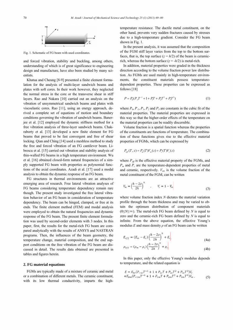
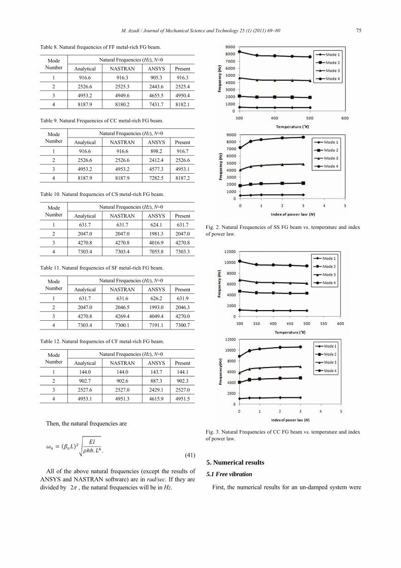
Fig. 2. Natural Frequencies of SS FG beam vs. temperature and index of power law.
Fig. 3. Natural Frequencies of CC FG beam vs. temperature and index of power law.
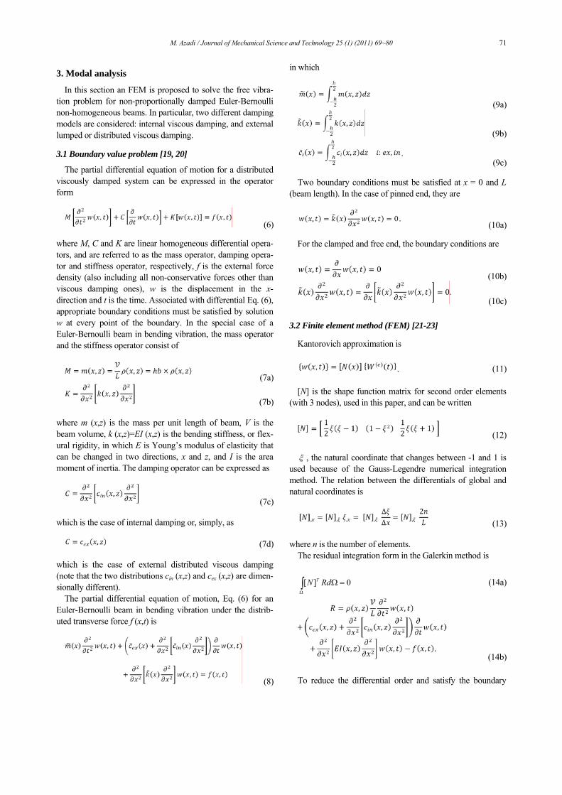
Table 8. Natural frequencies of FF metal-rich FG beam.
Natural Frequencies (Hz), N=0 Mode Number Analytical NASTRAN ANSYS Present
1 916.6 916.3 905.3 916.3
2 2526.6 2525.3 2443.6 2525.4
3 4953.2 4949.6 4655.5 4950.4
4 8187.9 8180.2 7431.7 8182.1
Table 9. Natural Frequencies of CC metal-rich FG beam.
Natural Frequencies (Hz), N=0 Mode Number Analytical NASTRAN ANSYS Present
1 916.6 916.6 898.2 916.7
2 2526.6 2526.6 2412.4 2526.6
3 4953.2 4953.2 4577.3 4953.1
4 8187.9 8187.9 7282.5 8187.2
Table 10. Natural frequencies of CS metal-rich FG beam.
Natural Frequencies (Hz), N=0 Mode Number Analytical NASTRAN ANSYS Present
1 631.7 631.7 624.1 631.7
2 2047.0 2047.0 1981.3 2047.0
3 4270.8 4270.8 4016.9 4270.8
4 7303.4 7303.4 7055.8 7303.3
Table 11. Natural frequencies of SF metal-rich FG beam.
Natural Frequencies (Hz), N=0 Mode Number Analytical NASTRAN ANSYS Present
1 631.7 631.6 626.2 631.9
2 2047.0 2046.5 1993.0 2046.3
3 4270.8 4269.4 4049.4 4270.0
4 7303.4 7300.1 7191.1 7300.7
Table 12. Natural frequencies of CF metal-rich FG beam.
Natural Frequencies (Hz), N=0 Mode Number Analytical NASTRAN ANSYS Present
1 144.0 144.0 143.7 144.1
2 902.7 902.6 887.3 902.3
3 2527.6 2527.0 2429.1 2527.0
4 4953.1 4951.3 4615.9 4951.5

76 M. Azadi / Journal of Mechanical Science and Technology 25 (1) (2011) 69~80
studied. The main purpose of this paper, therefore, was to study simply-supported FG beams.
The natural frequencies for a simply-supported metal-rich FG beam were calculated by ANSYS and NASTRAN soft-ware, using beam elements, and also by theoretical solutions.
The results for N=0 are listed in Table 4. As can be seen in Table 4, the analytical method and the re-
sults for NASTRAN software and the present method all show the same answers. But the results for ANSYS software show varying extents of errors.
Fig. 4. Natural Frequencies of FF FG beam vs. temperature and index of power law.
Fig. 5. Natural Frequencies of CS FG beam vs. temperature and index of power law.
Fig. 6. Natural Frequencies of CF FG beam vs. temperature and index of power law.
Fig. 7. Natural Frequencies of SF FG beam vs. temperature and index of power law.
M. Azadi / Journal of Mechanical Science and Technology 25 (1) (2011) 69~80 77
The natural frequencies of a simply-supported FG beam for different Ns (index of power law), in ambient temperature (T=300 °K) are listed in Table 5. Then, for various tempera-tures and N=1, the natural frequencies of a simply-supported FG beam are calculated and listed in Table 6. In Table 7, the natural frequencies of a simply-supported FG beam are listed for the various geometrical parameters (L and h/b) using N=1.
As the results show, the natural frequency of the FG beam increases as the power law index N increases when approach-ing the homogeneous ceramic side. The effect of temperature on the natural frequency of the FG beam is to reduce the natu-ral frequency with increasing in temperature.
By increasing the length of the beam, the natural frequency was decreased as expected. By increasing in parameter h/b, the natural frequency was increased.
For the other boundary conditions (FF, CC, CS, SF and CF) of the FG beam, the natural frequencies calculated by ANSYS and NASTRAN software, and the theoretical and present methods, are listed in Tables 8-12.
As it apparent, for the different boundary conditions, the present method incurs a small error in most of boundary con-ditions, but its accuracy is sufficient.
Some of the above results (only for the first 4 modes) are
Table 13. First complex frequency for different Ns.
N First Damped Natural Frequency (Hz)
0.0 -0.112710 + 448.78i
0.5 -0.087399 + 502.12i
1.0 -0.078576 + 519.43i
2.0 -0.071371 + 533.14i
3.0 -0.068243 + 538.99i
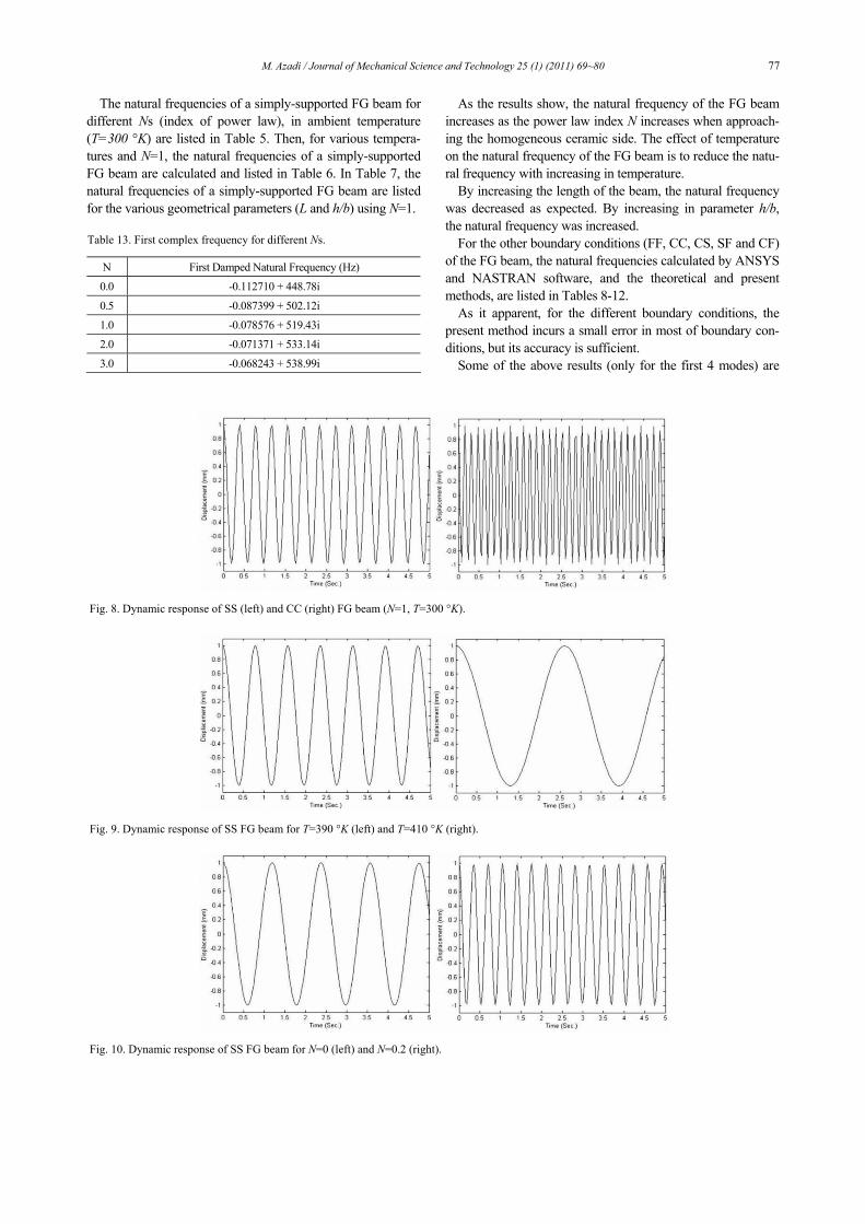
Fig. 8. Dynamic response of SS (left) and CC (right) FG beam (N=1, T=300 °K).
Fig. 9. Dynamic response of SS FG beam for T=390 °K (left) and T=410 °K (right).
Fig. 10. Dynamic response of SS FG beam for N=0 (left) and N=0.2 (right).

78 M. Azadi / Journal of Mechanical Science and Technology 25 (1) (2011) 69~80
also drawn in some of the figures (Fig. 2 to Fig. 7) for various boundary conditions, different temperatures and Ns. The re-sults show that by increasing the power law index N, the natu-ral frequencies of the FG beam increase according to obtained homogeneous ceramic property, which is harder than metal. And by increasing the temperature, the natural frequencies of the FG beam are decreased as the material becomes softer at
higher temperatures. Finally, the first damped natural frequencies of a FG beam
with a distributed damper (cex=0.1 Kg/Sec) located along the beam, are listed in Table 13 for simply-supported state and different Ns. As can be seen, the magnitude of the first damped natural frequency of the FG beam under the simply-supported condition increases when N increases.
Fig. 11. Dynamic response of SS FG beam for L=0.2 m (left) and L=0.3 m (right).
Fig. 12. Dynamic response of SS FG beam for h/b=2 (left) and h/b=3 (right).
Fig. 13. Dynamic response of FG beam for SS (left) and CC conditions (right).
Fig. 14. Dynamic response of SS FG beam for N=0 (left) and N=0.2 (right).

M. Azadi / Journal of Mechanical Science and Technology 25 (1) (2011) 69~80 79
5.2 Forced vibration
Initially, the numerical results for an un-damped system and various boundary conditions were studied. The initial condi-tions are as below.
An excitation external force, Sin (t), was applied to the middle point of the beam. For N=1 and the ambient tempera-ture (T=300 °K), the dynamic responses for the various boundary conditions such as SS and CC are plotted for the middle point of the beam, in Fig. 8.
As is apparent, by increasing the number of oscillations in a certain period of time, the period is decreased and so the natu-ral frequency is increased. Then, the natural frequencies of the simply-supported condition are less than those of the clamped-clamped condition, as expected.
Fig. 9 shows the dynamic response of the middle point of the simply-supported FG beam for N=1 and different tem-peratures (T=390 and 410 °K). The dynamic response of the middle point of the simply-supported FG beam is drawn in Fig. 10 for T=300 °K and a different index of power law (N=0 and 0.2). The results show that the effect of temperature on the natural frequency of the FG beam was to reduce the natural frequency with increase in the temperature. Also, the natural frequency of the FG beam increased as the power law index (N) increased when approaching the homogeneous ceramic side. Fig. 11 and Fig. 12 show the effects of the geometrical parameters on the natural frequencies of the simply-supported FG beam. Fig. 11, at issue are for different lengths of beam (L=0.2 and 0.3 m) and N=1, and ambient temperature and in Fig. 12, the parameter h/b of the dynamic response of the sim-ply-supported FG beam, also for N=1 and ambient tempera-ture. As can be seen, by increasing the length of the beam, the natural frequency decreases and by increasing the parameter h/b, the natural frequency increases, as expected.
Finally, a damped system was considered. The dynamic re-sponses of the FG beam with a distributed external damper (cex=0.1 Kg/Sec) located along the beam are drawn for N=1, ambient temperature and the SS and CC conditions in Fig. 13; for different indexes of power law (N=1 and 3), ambient tem-
perature and the simply-supported FG beam in Fig. 14; and for different temperatures (T=390 and 410 °K), N=1 and the simply-supported FG beam in Fig. 15.
As the results show, the damped natural frequency of the FG beam exhibits the same behavior, such as natural fre-quency which increasing with increasing N and decreasing with increasing temperature.
6. Conclusion
As discussed in this paper, an FEM free and forced lateral vibration analysis of FG beams was performed. The material properties were assumed to be temperature-dependent, and were graded in the thickness direction according to a simple power law distribution of volume fractions of the constituents.
The natural frequencies were obtained for FG beams under various boundary conditions including SS, FF, CC, SF, CF and CS. Initially, the FG beam was assumed to be isotropic (metal rich) and the results were compared with the analytical solution and the results for ANSYS and NASTRAN software. Then, dynamic responses were obtained for different states of FG beams.
The first results showed that the analytical method and the results for NASTRAN software and the present method in-cluded the same answers. The numerical results of the free and forced vibration analysis showed that the effect of temperature on the natural frequency of the FG beam was to reduce the natural frequency with increase the temperature. Also, the natu-ral frequency of the FG beam increased as the power law index N increased when approaching the homogeneous ceramic side. Then, with an increase in the length of the beam, the natural frequency decreased as expected and with an increase in the parameter h/b, the natural frequency increased. The first damped natural frequency of the FG beam under the simply-supported condition increased when N was increased.
References
[1] M. Koizumi, FGM activities in Japan, Composites, 28 (Part B) (1997) 1-4.
[2] M. Koizumi and M. Niino, Overview of FGM research ac-tivities in Japan, Material Research Society Bulletin, 20 (1995) 19-21.
Fig. 15. Dynamic response of SS FG beam for T=390 °K (left) and T=410 °K (right).
80 M. Azadi / Journal of Mechanical Science and Technology 25 (1) (2011) 69~80
[3] K. Ichikawa, Functionally Graded Materials in the 21st Cen-tury, A Workshop on Trends and Forecasts, Boston, USA (2001).
[4] B.V. Sankar and J.T. Tzeng, Thermal stress in functionally graded beams, AIAA Journal, 40 (2002) 1228-1232.
[5] M. Azadi and M. Azadi, Nonlinear transient heat transfer and thermoelastic analysis of thick-walled FGM cylinder with temperature-dependent material properties using Her-mitian transfinite element, Journal of Mechanical Science and Technology, 23 (10) (2009) 2635-2644.
[6] M. Azadi and M. Shariyat, Nonlinear transient transfinite element thermal analysis of thick-walled FGM cylinders with temperature-dependent material properties, Meccanica, 45 (3) (2010) 305-318.
[7] S. Suresh and A. Mortensen, Fundamentals of Functionally Graded Materials, IOM communications, London (1998).
[8] T. P. Khatua and Y. K. Cheung, Bending and vibration of multi layer beams and plates, International Journal for Nu-merical Methods in Engineering, 6 (1973) 11-24.
[9] T. P. Khatua and Y. K. Cheung, Stability analysis of multi-layer sandwich structures, AIAA Journal, 9 (1973) 1233-1234.
[10] Y. V. K. S. Rao and B. C. Nakara, Vibrations of unsym-metrical sandwich beams and plates with visco-elastic cores, Journal of Sound and Vibration, 34 (1974) 309-326.
[11] D. K. Rao, Frequency and loss factors of sandwich beams with various boundary conditions, Journal of Mechanical Engineering Science, 20 (1978) 271-282.
[12] J. R. Banerjee, Free vibration of sandwich beams using dynamic stiffness method, Journal of Computers and Struc-tures, 81 (2003) 1915-1922.
[13] A. Chakraborty, S. Gopalakrishnan and J. N. Reddy, A new beam finite element for the analysis of functionally graded materials, International Journal of Mechanical Science, 45 (2003) 519-539.
[14] L. F. Qian and H. K. Ching, Static and dynamic analysis of 2-D functionally graded elasticity by using meshless local Petrov-Galerkin method, Journal of Chinese Institute Engi-neering, 27 (2004) 491-503.
[15] L. Librescu, S. Y. Oh and O. Song, Thin-walled beams made of functionally graded materials and operating in a high temperature environment: vibration and stability, Jour-nal of Thermal Stresses, 28 (2005) 649-712.
[16] L. Wu, Q. S. Wang and I. Elishakoff, Semi-inverse method for axially functionally graded beams with an anti- symmetric vibration mode, Journal of Sound and Vibration,
284 (2005) 1190-1202. [17] M. Azadi and M. Damircheli, Dynamic Response of FGM
Beam using Modal Analysis and FEM considering Tempera-ture Dependency of Properties, Proceedings of the 7th Inter-national Conference on Composite Science and Technology (ICCST/7), American University of Sharjah, Sharjah, UAE, (2009).
[18] J. N. Reddy and C. D. Chin, Thermo-mechanical Analysis of Functionally Graded Cylinders and Plates, Journal Ther-mal Stresses, 21 (1998) 593-626.
[19] S. Sorrentino, S. Marchesiello and B. Piombo, A new ana-lytical technique for vibration analysis of non-proportionally damped beams, Journal of Sound and Vibration, 265 (2003) 765-782.
[20] S. Sorrentino, A. Fasana and S. Marchesiello, Analysis of non-homogenous Timoshenko beams with generalized damping distribution, Journal of Sound and Vibration (2007).
[21] T. J. R. Hughes, The Finite Element Method, Prentice-Hall International Inc. (1987).
[22] K. H. Huebner and E. A. Thornton, The Finite Element Method for Engineers, 2nd edition, A Wiley-Interscience Publication (1982).
[23] J. N. Reddy, An Introduction to The Finite Element Method, McGraw-Hill Inc. (1993).
[24] L. Meirovitch, Principles and Techniques of Vibrations, Prentice-Hall, Upper Saddle River NJ (1997).
[25] F. S. Tse, I. E. Morse and R. T. Hinkle, Mechanical Vibra-tions (Theory and Applications), Allyn and Bacon Inc. (1978).
Mohammad Azadi received his B.S. in Mechanical Engineering from Shiraz University, Iran, in 2006. He then earned his M.S. from K.N. Toosi University of Technology in 2008. He is currently a Ph.D candidate at Sharif University of Technology. His research interests include NVH (Noise,
Vibration and Harshness), Composites (especially FGMs), FEM (Finite Element Method), automotive engineering (espe-cially engines and vehicle structures), TBC (Thermal Barrier Coating) and fatigue including HCF (High Cycle Fatigue), LCF (Low Cycle Fatigue) and TMF (Thermo-Mechanical Fatigue).