francisco salesa greus ific (csic–universitat de valència, spain) representing the km3net...
TRANSCRIPT

Francisco Salesa GreusIFIC (CSIC–Universitat de València, Spain)
Representing the KM3NeT Consortium
4th International Workshop on Very Large Volume Neutrino Telescopes for the Mediterranean Sea
(VLVnT09)
Athens, Greece, 13-15 October 2009

• The future KM3NeT detector.• Time calibration requirements.• Time calibration systems for KM3NeT:
– Laboratory calibration.– Internal clock calibration.– Optical calibration system:
• The Nanobeacon.• The Laser Beacon.
– Cross-check methods: K40 and atmospheric muons.• Summary.
10/15/2009 2F. Salesa - VLVNT09

• KM3NeT will be a NT of at least 1 km3 of sea water (Mediterranean Sea) and a deep-sea infrastructure for earth and sea science.
• Formed by 41 institutions from 10 countries.• To be deployed after 2013.
10/15/2009 F. Salesa - VLVNT09 3
c=43°

• The angular resolution is critical in a NT. A good angular resolution provides the needed point spread function to resolve cosmic neutrino sources from the atmospheric background.
• The angular resolution relies on a good positioning and time calibration.• Working within the specifications the attainable angular resolution of KM3NeT is better than
0.1° for E > 100 TeV.
The absolute time resolutionabsolute time resolution (provides a specific time for each neutrino event w.r.t. UT) depends on:
GPS timing. Detector electronic paths.
In order to obtain correlations with the physics phenomena (e.g. GRB) an accuracy of 1 ms is enough.
Relative time resolutionRelative time resolution (among OMs) depends on: OM transit time spread (TTS), typically ~1-1.5 ns. Optical properties of the sea water: light scattering + chromatic dispersion
(~1-1.5 ns) for light coming from a distance of 50 m. Electronics (<0.5 ns).
All these components give an overall unavoidable time spread of 1-2 ns. The determination of the calibration constants with a ≤1 ns fulfils the
requirements for relative time resolution.
10/15/2009 4F. Salesa - VLVNT09

• Before the deployment the time calibration constants are determined in the laboratory.• The calibration consists of two main parts: one to obtain the clock-phase delay, another to obtain
the intrinsic OM time offset:– The clock-phase delay is given very precisely by the internal clock calibration.– A special setup should be designed for the intrinsic time offset computation.
• The special setup can also be used for additional calibrations (e.g. electronics & charge) .• The internal clock calibration is repeated in situ.
10/15/2009 5F. Salesa - VLVNT09
Optical fibres
Signal splitte
r
Laser
START STOPGPS E/
O/E
START STOP
On-shore Station
Time Digital Converter
In-situ
Echo-based system
Junction Boxoptical splitter
Special calibration setupSpecial calibration setup

• The experience from the previous projects shows that a system of external light sources with a known emission time ensures the time calibration and provides measurements of the optical water properties (c.f. H. Yepes talk).
• Decoupling the intra/inter detection unit (DU) calibration seems the best solution: – The calibration in the same storey and in the same DU will be performed by a group of Nanobeacons.
– The calibration among DU will be performed by several Laser Beacons.
• The calibration constants are obtained putting all the information together.
10/15/2009 6F. Salesa - VLVNT09
Laser
LED
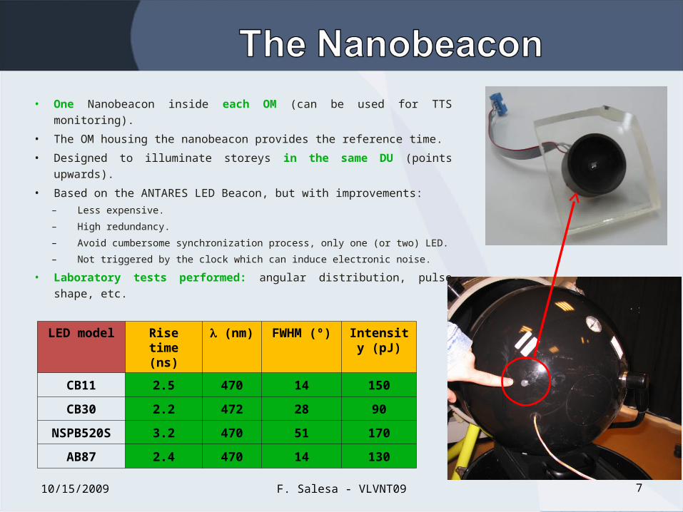
• One Nanobeacon inside each OM (can be used for TTS monitoring).
• The OM housing the nanobeacon provides the reference time.
• Designed to illuminate storeys in the same DU (points upwards).
• Based on the ANTARES LED Beacon, but with improvements:– Less expensive.
– High redundancy.
– Avoid cumbersome synchronization process, only one (or two) LED.
– Not triggered by the clock which can induce electronic noise.
• Laboratory tests performed: angular distribution, pulse shape, etc.
10/15/2009 7F. Salesa - VLVNT09
LED model Rise time (ns)
(nm) FWHM (º)
Intensity (pJ)
CB11 2.5 470 14 150
CB30 2.2 472 28 90
NSPB520S 3.2 470 51 170
AB87 2.4 470 14 130

• The circuit works at a nominal 24 V.• The flashing rate depends on the feeding voltage (no external
trigger). It is 25 kHz at 24 V and requires only an on/off interface.
• One single LED is expected to reach 350 m (90 pJ ~2 x 10⁸ photons). In ANTARES one LED reach ~200 m.
• First tests performed mounting the Nanobeacon in an OM from ANTARES in water.
10/15/2009 F. Salesa - VLVNT09 8
RMS ~ 1 nsRMS ~ 1 ns
Trigger signal w.r.t. OM signalTrigger signal w.r.t. OM signal
PRELIMINARYPRELIMINARY

• In the peak region (± 10°) the KM3NeT LED emits 1.5 orders of magnitude more than the ANTARES LED.
• An opening angle of 15° is sufficient to illuminate OMs placed above, even in a perpendicular arrangement (NuONE DU).
• The pre-selected model is the Avago HLMP-CB30 LED.
10/15/2009 F. Salesa - VLVNT09 9
50m
6m
- KM3Net LED model (uncleaved)
- ANTARES LED model (cleaved)
- KM3Net LED model (uncleaved)
- ANTARES LED model (cleaved)

• Based on the ANTARES Laser Beacon (diode pumped Q-switched Nd-YAG laser).
• Some Laser Beacons will be deployed at the bottom of several DU.
• Alternatively to the previous green ANTARES laser ( = 532 nm). There is the possibility of working with a blue laser ( = 473 nm).
• The amount of light emitted can be tuned by means of a voltage controlled optical attenuator.
• An internal photodiode reads the signal and provides its timestamp.
10/15/2009 F. Salesa - VLVNT09 10
LaserProperties
Blue (473 nm)
ANTARESGreen (532
nm)
NewGreen (532
nm)
Average power
20 mW ~0.8 mW 45 mW
Rate kHz range kHz range kHz range
Pulse energy
5 J 1 J 45 J
Rise time < 1.5 ns ~ 0.6 ns ~0.15 ns
Liquid Crystal Retarder
Polarizing Beam-Splitter
Laser Head Polarizing cube beam-splitter
Liquid Crystal Head
Variable Voltage

10/15/2009 F. Salesa - VLVNT09 11
Calibration constants correction
RMS ~ 0.7 nsRMS ~ 0.7 ns
Time difference between a LED OB and an OM
Electronics contribution less
than 0.5 ns
RMS ~ 2 ns
RMS ~ 2 ns
RMS ~ 0.6 ns
RMS ~ 0.6 ns
Only 15% larger than 1 ns
Retuning of feeding HV can be corrected with the
OBs
00
0
PRELIMINARYPRELIMINARY
σ ~ 0.4 nsσ ~ 0.4 ns

• Background signal can be used to cross-check the time calibration.• For configurations with adjacent OMs in the same storey, the K40
present in the salt water can be used for charge and intra-storey time calibration of the detector.
• Atmospheric muons (both up-going and down-going) can be used for the calibration among and in the same DU.
10/15/2009 F. Salesa - VLVNT09 12
40K
40Ca
e- ( decay)
Cherenkov
Gaussian peak on coincidence plot
OM 0
OM 1
OM 2
Taking differences by pairs

• The check of the time offsets measured by the K40 shows the improvement using the calibration constants computed by the OB system.
• The calibration constants computed with intense light sources (OBs) are still valid at lower intensities (K40).
10/15/2009 F. Salesa - VLVNT09 13
RMS=0.71 ns RMS=0.50 ns
Laboratory Calibration constantsLaboratory Calibration constants OB calibration constantsOB calibration constants
• The time calibration of KM3NeT based on the previous NT projects experience.
• An absolute time calibration of 1 ms is enough and a relative time calibration at the nanosecond level is desirable.
• A first calibration will be performed in the laboratories.• An optical calibration system will be used for the in situ time
calibration (results from ANTARES encourages that system).• Decoupling of intra/inter DU calibration.• Optical and muon background can be used as a cross-check.• Thanks to the time calibration systems, KM3NeT will be able to
achieve an angular resolution better than 0.1° for E > 100 TeV.
10/15/2009 14F. Salesa - VLVNT09