français español - fujitsu generalim)uty...it may cause erroneous operation. ... instruction book...
TRANSCRIPT
PART NO. 9373328148-02
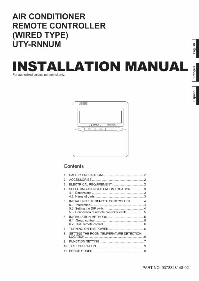
INSTALLATION MANUAL
AIR CONDITIONERREMOTE CONTROLLER(WIRED TYPE)UTY-RNNUM
Contents1. SAFETY PRECAUTIONS ............................................. 22. ACCESSORIES ............................................................ 23. ELECTRICAL REQUIREMENT ..................................... 24. SELECTING AN INSTALLATION LOCATION ............... 3
4.1. Dimensions ............................................................ 34.2. Name of parts ......................................................... 3
5. INSTALLING THE REMOTE CONTROLLER ............... 45.1. Installation .................................................................45.2. Setting the DIP switch ............................................ 45.3. Connection of remote controller cable ................... 5
6. INSTALLATION METHODS .......................................... 56.1. Group control ......................................................... 56.2. Dual remote control ............................................... 6
7. TURNING ON THE POWER ......................................... 68. SETTING THE ROOM TEMPERATURE DETECTION
LOCATION .......................................................................69. FUNCTION SETTING ................................................... 710. TEST OPERATION ....................................................... 911. ERROR CODES ........................................................... 9
For authorized service personnel only.
Engl
ish
Fran
çais
Espa
ñol
9373328148-02_IM_EN_FR_SP.indb 19373328148-02_IM_EN_FR_SP.indb 1 9/14/2010 1:14:03 PM9/14/2010 1:14:03 PM

En-2
1. SAFETY PRECAUTIONSLet the customer keep this installation manual because it • is needed when the air conditioner or remote controller is serviced or moved.
WARNINGThis mark indicates procedures which, if improperly performed, might lead to the death or serious injury of the user.
For the air conditioner to operate satisfactorily, install it as • outlined in this installation manual.Installation work must be performed in accordance with • national wiring standards by authorized personnel only.Do not turn on the power until all installation work is • complete.
CAUTIONThis mark indicates procedures which, if improperly performed, might possibly result in personal harm to the user, or damage to property.
When detecting the room temperature using the remote • controller, please set up the remote controller according to the following conditions.If the remote controller is not located properly, the correct room temperature will not be detected, and thus abnormal conditions like “not cooled” or “not heated” will occur even if the air-conditioner is running normally.
Locate where an average • temperature for the room being air conditioned will be sensed.Do not locate directly exposed • to the outlet air from the air-conditioner.Locate out of direct sunlight.• Locate away from the infl uence of other heat sources.•
Do not touch the remote controller PC board and PC • board parts directly with your hands.Do not wire the remote controller cable together with • or parallel to the connection cables, and power supply cables of the indoor unit and outdoor unit. It may cause erroneous operation.When installing cable near a source of electromagnetic • waves, use shielded wire.Do not set the DIP switches, either on the air conditioner • or the remote controller, in any way other than indicated in this manual or the manual that is supplied with the air conditioner. Doing so may result in improper operation.
Temperature sensor
2. ACCESSORIESThe following installation parts are supplied. Use them as required.
Name and Shape Q’ty ApplicationInstallation manual
1
This manual
Operating manual
1
Instruction book for operation
Remote controller cable
1
For connecting the remote controller
Connecting cable (*1)
1
For connecting the remote controller cable to the wall mounted type indoor unit
Tapping screw(M4 x 16mm)
2
For installing the remote controller
Binder1
For remote controller and remote controller cable binding
Tapping screw(M4 x 14mm) (*1)
1
For installing the remote controller cable to the indoor unit
Cable clamper (*1)1
For installing the remote controller cable to the indoor unit
(*1) Use only if the remote controller cable must be modifi ed for the indoor unit model.
3. ELECTRICAL REQUIREMENTWhen connecting the remote controller use the following wiring.
Cable Cable size RemarksRemote con-troller cable 22AWG Sheathed PVC
cable, Polar 3 core * We recommend that you purchase our service parts for the
remote controller cable. Contact service personnel to pur-chase this.
9373328148-02_IM_EN_FR_SP.indb 29373328148-02_IM_EN_FR_SP.indb 2 9/14/2010 1:15:24 PM9/14/2010 1:15:24 PM

En-3
4.2. Name of parts
With cover open ●
1
2
3
4
5
6
7
8
9
10
11
12
13
14
15
Display panel
Display panel ●16 17 18 19
2021
22 2624 2523 27 28
1 “ ”, “ ” (Set Temperature Button)
2 “ ” (Timer Mode/Clock Adjust Button)
3 “ ” (Day/Day OFF Button)4 “ ” (Set Back Button)5 “ ”, “ ” (Set Time Button)6 “ ” (Timer Delete Button)7 “ ” (Timer Set Button)8 “ ” (Start/Stop Button)9 “ ” (Mode Button)0 “ ” (Fan Control Button)A “ ” (Horizontal airfl ow direction and swing Button)B “ ” (Vertical airfl ow direction and swing Button)C “ ” (Economy/Thermo Sen-
sor Button)D “ ” (Maintenance/Filter Reset
Button)E Operation LampF Day DisplayG Operation Lock DisplayH Temperature DisplayI Fan Speed DisplayJ Timer Mode DisplayK Operation Mode DisplayL Timer and Clock DisplayM Filter DisplayN Economy DisplayO Thermo Sensor DisplayP Vertical Swing DisplayQ Horizontal Swing DisplayR Defrost Display
4. SELECTING AN INSTALLATION LOCATION
4.1. Dimensions
4-3/4 (120)
4-3/
4 (1
20)
23/32(18)
3-9/
32 (
83.5
)
5/8
(15.
3)2-
1/2
(63.
5)
Hole
1-25
/32
3/16
(4.5
)
11/32(9)
1/2
(12.
5)
(45.
3)
Hole × 2Hole × 3
3/16
(4.5
)
3/16 (4.5)
1/4(6)
1-3/16(30)
1-5/16(33.5)
29/32(23)
Unit: in. (mm)
9373328148-02_IM_EN_FR_SP.indb 39373328148-02_IM_EN_FR_SP.indb 3 9/14/2010 1:15:25 PM9/14/2010 1:15:25 PM
En-4
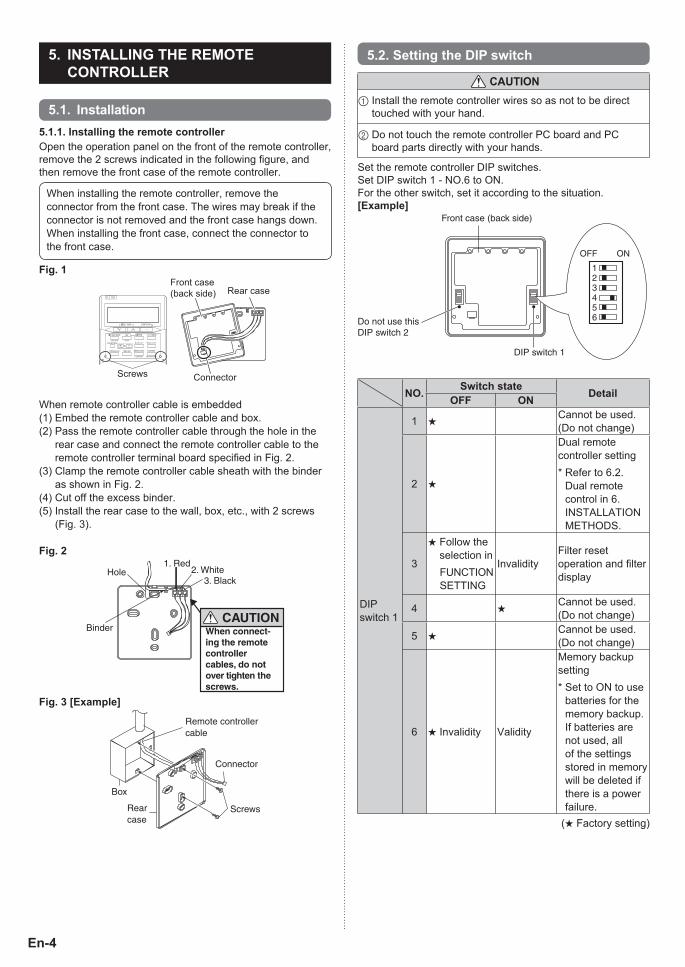
5.2. Setting the DIP switch
CAUTION1 Install the remote controller wires so as not to be direct
touched with your hand.
2 Do not touch the remote controller PC board and PC board parts directly with your hands.
Set the remote controller DIP switches.Set DIP switch 1 - NO.6 to ON.For the other switch, set it according to the situation.[Example]
DIP switch 1
Front case (back side)
ONOFF
123456Do not use this
DIP switch 2
NO. Switch state DetailOFF ON
DIP switch 1
1 ★Cannot be used. (Do not change)
2 ★
Dual remote controller setting* Refer to 6.2.
Dual remote control in 6. INSTALLATION METHODS.
3
★ Follow the selection in
FUNCTION SETTING
InvalidityFilter reset operation and fi lter display
4 ★Cannot be used. (Do not change)
5 ★Cannot be used. (Do not change)
6 ★ Invalidity Validity
Memory backup setting* Set to ON to use
batteries for the memory backup. If batteries are not used, all of the settings stored in memory will be deleted if there is a power failure.
(★ Factory setting)
5. INSTALLING THE REMOTE CONTROLLER
5.1. Installation5.1.1. Installing the remote controllerOpen the operation panel on the front of the remote controller, remove the 2 screws indicated in the following fi gure, and then remove the front case of the remote controller.
When installing the remote controller, remove the connector from the front case. The wires may break if the connector is not removed and the front case hangs down.When installing the front case, connect the connector to the front case.
Fig. 1
SET BACK
Front case (back side) Rear case
Screws Connector
When remote controller cable is embedded(1) Embed the remote controller cable and box.(2) Pass the remote controller cable through the hole in the
rear case and connect the remote controller cable to the remote controller terminal board specifi ed in Fig. 2.
(3) Clamp the remote controller cable sheath with the binder as shown in Fig. 2.
(4) Cut off the excess binder.(5) Install the rear case to the wall, box, etc., with 2 screws
(Fig. 3).
Fig. 2
BinderCAUTION
1. Red2. White
3. BlackHole
▼
When connect-ing the remote controller cables, do not over tighten the screws.
Fig. 3 [Example]
Remote controllercable
Box
Screws
Connector
Rearcase
9373328148-02_IM_EN_FR_SP.indb 49373328148-02_IM_EN_FR_SP.indb 4 9/14/2010 1:15:27 PM9/14/2010 1:15:27 PM
En-5
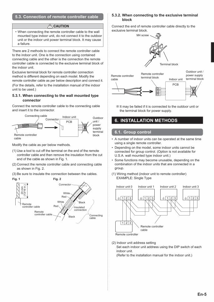
5.3. Connection of remote controller cable
CAUTIONWhen connecting the remote controller cable to the wall • mounted type indoor unit, do not connect it to the outdoor unit or the indoor unit power terminal block. It may cause a failure.
There are 2 methods to connect the remote controller cable to the indoor unit. One is the connection using contained connecting cable and the other is the connection the remote controller cable is connected to the exclusive terminal block of the indoor unit.Exclusive terminal block for remote controller connection method is different depending on each model. Modify the remote controller cable as per below description and connect it.(For the details, refer to the installation manual of the indoor unit to be used.)
5.3.1. When connecting to the wall mounted type connector
Connect the remote controller cable to the connecting cable and insert it to the connector.
PCB
Connecting cable
Remote controller cable
Indoor unit Outdoor unit / power supply terminal block
Connector
Modify the cable as per below methods.
(1) Use a tool to cut off the terminal on the end of the remote controller cable and then remove the insulation from the cut end of the cable as shown in Fig. 1.
(2) Connect the remote controller cable and connecting cable as shown in Fig. 2.
(3) Be sure to insulate the connection between the cables.
Connecting cable
Connector
Fig. 1 Fig. 2
WhiteRed
WhiteRed
Black
Black
Insulatedconnection
Remotecontroller cable
Remotecontroller cable
20 m
m
(13/
16 in
.)
5.3.2. When connecting to the exclusive terminal block
Connect the end of remote controller cable directly to the exclusive terminal block.
Terminal block
M4 screw
PCB
Indoor unit
Outdoor unit /power supplyterminal block
Remote controllerterminal blockRemote controller
cable
It may be failed if it is connected to the outdoor unit or the terminal block for power supply.
d 6. INSTALLATION METHODS
6.1. Group controlA number of indoor units can be operated at the same time • using a single remote controller.Depending on the model, some indoor units cannot be • connected for group control. (Option is not available for U.S.A. wall mounted type indoor unit.)Some functions may become unusable, depending on the • combination of the indoor units that are connected in a group.
(1) Wiring method (indoor unit to remote controller) EXAMPLE: Single Type
Remote controller
Remote controllercable
Indoor unit 0 Indoor unit 1 Indoor unit 2 Indoor unit 3
1 2 3
1 2 3
1 2 3 1 2 3 1 2 3
(2) Indoor unit address setting Set each indoor unit address using the DIP switch of each
indoor unit. (Refer to the installation manual for the indoor unit.)
9373328148-02_IM_EN_FR_SP.indb 59373328148-02_IM_EN_FR_SP.indb 5 9/14/2010 1:15:27 PM9/14/2010 1:15:27 PM
En-6
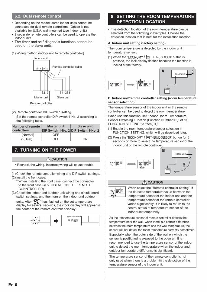
6.2. Dual remote controlDepending on the model, some indoor units cannot be • connected for dual remote controllers. (Option is not available for U.S.A. wall mounted type indoor unit.)2 separate remote controllers can be used to operate the • indoor units.The timer and self-diagnosis functions cannot be • used on the slave units.
(1) Wiring method (indoor unit to remote controller)
Remote controller cable
Indoor unit
Slave unitMaster unit
1 2 31 2 3
1 2 3
Remote controller
(2) Remote controller DIP switch 1 setting Set the remote controller DIP switch 1-No. 2 according to
the following table.
Number of remote controllers
Master unit Slave unitDIP Switch 1-No. 2 DIP Switch 1-No. 2
1 (Normal) OFF –2 (Dual) OFF ON
7. TURNING ON THE POWER
CAUTIONRecheck the wiring. Incorrect wiring will cause trouble.•
(1) Check the remote controller wiring and DIP switch settings.(2) Install the front case. * When installing the front case, connect the connector
to the front case (in 5. INSTALLING THE REMOTE CONNTROLLER).
(3) Check the indoor and outdoor unit wiring and circuit board switch settings, and then turn on the indoor and outdoor units. After “9c” has fl ashed on the set temperature display for several seconds, the clock display will appear in the center of the remote controller display.
SU MO TU WE TH FR SA
8. SETTING THE ROOM TEMPERATURE DETECTION LOCATION
The detection location of the room temperature can be • selected from the following 2 examples. Choose the detection location that is best for the installation location.
A. Indoor unit setting (factory setting)The room temperature is detected by the indoor unit temperature sensor.(1) When the “ ” button is
pressed, the lock display fl ashes because the function is locked at the factory.
AIndoor unit
B. Indoor unit/remote controller setting (room temperature sensor selection)The temperature sensor of the indoor unit or the remote controller can be used to detect the room temperature.When use this function, set “Indoor Room Temperature Sensor Switching Function (Function Number:42)” of “9. FUNCTION SETTING” to “Yes(01)”.(1) Enable the room temperature sensor selection in
FUNCTION SETTING, which will be described later.(2) Press the “ ” button for 5
seconds or more to select the temperature sensor of the indoor unit or the remote controller.
BIndoor unit
CAUTION When select the “Remote controller setting”, if the detected temperature value between the temperature sensor of the indoor unit and the temperature sensor of the remote controller varies signifi cantly, it is likely to return to the control status of temperature sensor of the indoor unit temporarily.
As the temperature sensor of remote controller detects the temperature near the wall, when there is a certain difference between the room temperature and the wall temperature, the sensor will not detect the room temperature correctly sometimes.Especially when the outer side of the wall on which the sensor is positioned is exposed to the open air, it is recommended to use the temperature sensor of the indoor unit to detect the room temperature when the indoor and outdoor temperature difference is signifi cant.
The temperature sensor of the remote controller is not only used when there is a problem in the detection of the temperature sensor of the indoor unit.
9373328148-02_IM_EN_FR_SP.indb 69373328148-02_IM_EN_FR_SP.indb 6 9/14/2010 1:15:28 PM9/14/2010 1:15:28 PM
En-7
NOTES If the function to change the temperature sensor is used as shown in example A (other than example B), be sure to lock the detection location. If the function is locked, the lock display
will fl ash when the “ ” button is pressed.
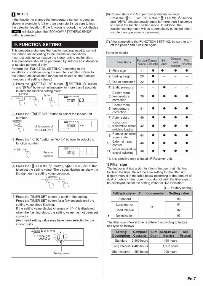
9. FUNCTION SETTINGThis procedure changes the function settings used to control the indoor unit according to the installation conditions. Incorrect settings can cause the indoor unit to malfunction. This procedure should be performed by authorized installation or service personnel only.Perform the “FUNCTION SETTING” according to the installation conditions using the remote controller. (Refer to the indoor unit installation manual for details on the function numbers and setting values.)(1) Press the “ ” button, “ ” button
and “ ” button simultaneously for more than 5 seconds to enter the function setting mode.
SU MO TU WE TH FR SA
(2) Press the “ ” button to select the indoor unit number.
SET BACK SU MO TU WE TH FR SA
Unit number of INDOOR UNIT
(3) Press the “ ” button or “ ” buttons to select the function number.
Function number
SU MO TU WE TH FR SA
(4) Press the “ ” button, “ ” button to select the setting value. The display fl ashes as shown to the right during setting value selection.
(5) Press the TIMER SET button to confi rm the setting. Press the TIMER SET button for a few seconds until the
setting value stops fl ashing. If the setting value display changes or if “- -” is displayed
when the fl ashing stops, the setting value has not been set correctly.
(An invalid setting value may have been selected for the indoor unit.)
SU MO TU WE TH FR SA
(6) Repeat steps 2 to 5 to perform additional settings. Press the “ ” button, “ ” button
and “ ” simultaneously again for more than 5 seconds to cancel the function setting mode. In addition, the function setting mode will be automatically canceled after 1 minute if no operation is performed.
(7) After completing the FUNCTION SETTING, be sure to turn off the power and turn it on again.
Function details
Functions Function number
Compact cassette
Slim duct
Compact wall
mounted
Wall mounted
1) Filter sign 11 *1
2) Ceiling height 20 – – –
3) Outlet directions 22 – – –
4) Static pressure – – – –
5)Cooler room temperature correction
30
6)Heater room temperature correction
31
7) Auto restart 40
8)Indoor room temperature sensor switching function
42
9) Remote controller signal code 44
10) External input control 46
11) Room temperature control switching 48
*1: It is effective only to install IR Receiver unit.
1) Filter signThe indoor unit has a sign to inform the user that it is time to clean the fi lter. Select the time setting for the fi lter sign display interval in the table below according to the amount of dust or debris in the room. If you do not wish the fi lter sign to be displayed, select the setting value for “No indication”.
(♦... Factory setting)
Setting description Function number Setting value
Standard
11
00
Long interval 01
Short interval 02
♦ No indication 03
The filter sign interval time is different according to Indoor unit type as follows.
Setting Description
Compact Cassette
Slim Duct
Compact Wall Mounted
Wall Mounted
Standard 2,500 hours 400 hours
Long interval 4,400 hours 1,000 hours
Short interval 1,250 hours 200 hoursSetting value
9373328148-02_IM_EN_FR_SP.indb 79373328148-02_IM_EN_FR_SP.indb 7 9/14/2010 1:15:29 PM9/14/2010 1:15:29 PM

En-8
2) Ceiling heightSelect the setting values in the table below according to the height of the ceiling.
(♦... Factory setting)
Setting Description Function Number
Setting Value
♦ Standard (2.7m)20
00
High ceiling (3.0m) 01
3) Outlet directionsSelect the setting values in the table below for using a 3-way outlet.
(♦... Factory setting)
Setting Description Function Number
Setting Value
♦ 4-way22
00
3-way 01
4) Static pressureSelect appropriate static pressure according to the installa-tion conditions.Please refer to the installation manual of each indoor unit for details.
5) Cooler room temperature correctionDepending on the installed environment, the room tempera-ture sensor may require a correction. The settings may be selected as shown in the table below.
(♦... Factory setting)
Setting Description Function Number
Setting Value
♦ Standard
30
00
Slightly Lower control 01
Lower control 02
Warmer control 03
6) Heater room temperature correctionDepending on the installed environment, the room tempera-ture sensor may require a correction. The settings may be changed as shown in the table below.
(♦... Factory setting)
Setting Description Function Number
Setting Value
♦ Standard
31
00
Lower control 01
Slightly warmer control 02
Warmer control 03
7) Auto restartEnable or disable automatic system restart after a power outage.
(♦... Factory setting)
Setting Description Function Number
Setting Value
♦ Yes40
00
No 01
* Auto restart is an emergency function such as for power fail-ure etc.
Do not start and stop the indoor unit by this function in nor-mal operation.
Be sure to operate by the control unit, or external input device.
8) Indoor room temperature sensor switching function(Only for Wired remote controller)The following settings are needed when use the control by Wired remote controller temperature sensor.
(♦... Factory setting)
Setting Description Function Number
Setting Value
♦ No42
00
Yes 01
* If setting value is “00” : Room temperature is controlled by the indoor unit temperature
sensor.* If setting value is “01” : Room temperature is controlled by either indoor unit tempera-
ture sensor or remote controller unit sensor.
9) Remote controller signal codeChange the indoor unit Signal Code, depending on the remote controllers.
(♦... Factory setting)
Setting Description Function Number
Setting Value
♦ A
44
00
B 01
C 02
D 03
10) External input control“Operation/Stop” mode or “Forced stop” mode can be elected.
(♦... Factory setting)
Setting Description Function Number
Setting Value
♦ Operation/Stop mode
46
00
(Setting forbidden) 01
Forced stop mode 02
9373328148-02_IM_EN_FR_SP.indb 89373328148-02_IM_EN_FR_SP.indb 8 9/14/2010 1:15:32 PM9/14/2010 1:15:32 PM
En-9
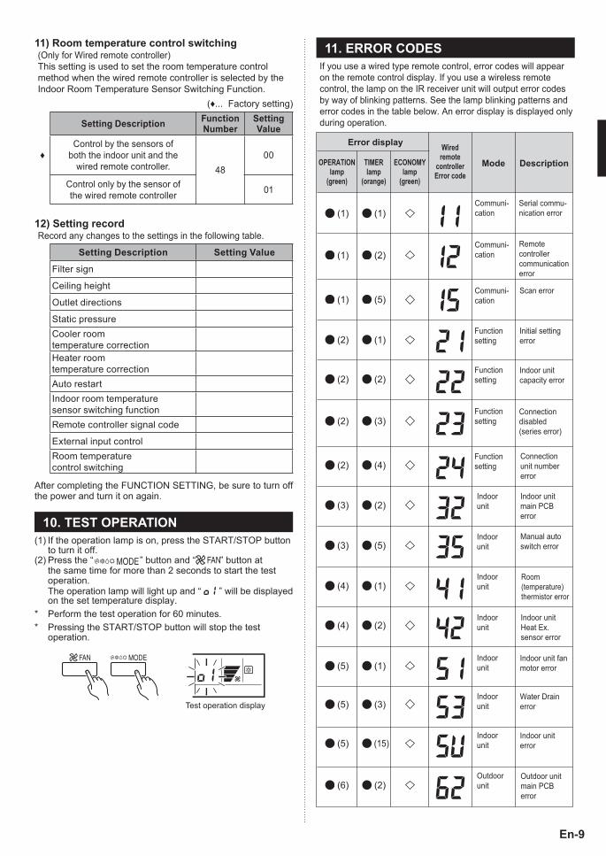
11) Room temperature control switching(Only for Wired remote controller)This setting is used to set the room temperature control method when the wired remote controller is selected by the Indoor Room Temperature Sensor Switching Function.
(♦... Factory setting)
Setting Description Function Number
Setting Value
♦Control by the sensors of
both the indoor unit and the wired remote controller. 48
00
Control only by the sensor of the wired remote controller 01
12) Setting recordRecord any changes to the settings in the following table.
Setting Description Setting Value
Filter sign
Ceiling height
Outlet directions
Static pressureCooler room temperature correctionHeater room temperature correctionAuto restartIndoor room temperature sensor switching functionRemote controller signal code
External input controlRoom temperature control switching
After completing the FUNCTION SETTING, be sure to turn off the power and turn it on again.
10. TEST OPERATION(1) If the operation lamp is on, press the START/STOP button
to turn it off.(2) Press the “ ” button and “ ” button at
the same time for more than 2 seconds to start the test operation.
The operation lamp will light up and “ \1 ” will be displayed on the set temperature display.
* Perform the test operation for 60 minutes.* Pressing the START/STOP button will stop the test
operation.
Test operation display
11. ERROR CODESIf you use a wired type remote control, error codes will appear on the remote control display. If you use a wireless remote control, the lamp on the IR receiver unit will output error codes by way of blinking patterns. See the lamp blinking patterns and error codes in the table below. An error display is displayed only during operation.
(6) (2)Outdoor unitmain PCBerror
Error display Wiredremote
controllerError code
Mode DescriptionOPERATIONlamp
(green)
TIMERlamp
(orange)
ECONOMYlamp
(green)
(1) (1)Communi-cation
Communi-cation
Communi-cation
Serial commu-nication error
(1) (2)Remotecontrollercommunicationerror
(2) (1)Functionsetting
Functionsetting
Functionsetting
Functionsetting
Initial settingerror
(1) (5)Scan error
(2) (2)Indoor unitcapacity error
(2) (3)Connectiondisabled(series error)
(2) (4)Connectionunit numbererror
(3) (5)Manual autoswitch error
(3) (2)Indoorunit
Indoorunit
Indoorunit
Indoorunit
Indoorunit
Indoor unitmain PCBerror
(4) (1)Room (temperature) thermistor error
(4) (2)Indoor unitHeat Ex. sensor error
(5) (1)Indoor unit fanmotor error
Indoorunit (5) (3)
Water Drainerror
Indoorunit
Outdoorunit
(5) (15)Indoor uniterror
9373328148-02_IM_EN_FR_SP.indb 99373328148-02_IM_EN_FR_SP.indb 9 9/14/2010 1:15:32 PM9/14/2010 1:15:32 PM
En-10
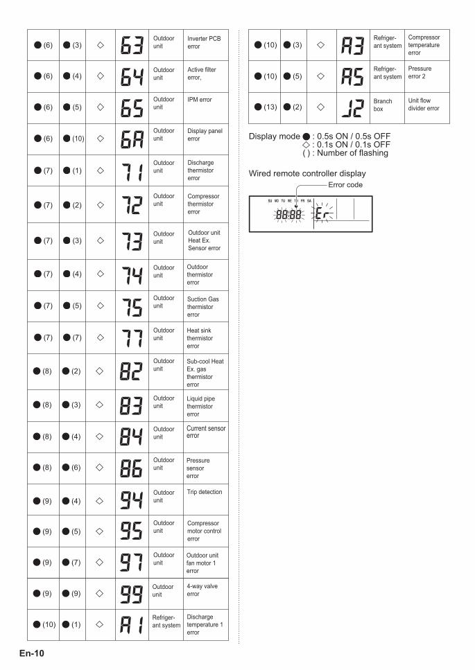
(6) (3)
(6) (4)
(7) (1)Dischargethermistorerror
(7) (2)Compressorthermistorerror
(7) (3)Outdoor unit Heat Ex. Sensor error
(7) (4)Outdoor thermistorerror
(7) (5)Suction Gas thermistorerror
(7) (7)Heat sink thermistorerror
(8) (2)Sub-cool HeatEx. gas thermistorerror
(8) (3)Liquid pipe thermistorerror
(8) (4)Current sensor error
(8) (6)Pressure sensorerror
(9) (5)Compressor motor control error
(9) (7)Outdoor unit fan motor 1error
Inverter PCBerror
Outdoorunit
Active filter error,
Outdoorunit
(6) (5)IPM errorOutdoor
unit
(6) (10)Display panel error
Outdoorunit
Outdoorunit
Outdoorunit
Outdoorunit
Outdoorunit
Outdoorunit
Outdoorunit
Outdoorunit
Outdoorunit
Outdoorunit
Outdoorunit
(9) (4)Trip detectionOutdoor
unit
Outdoorunit
Outdoorunit
(9) (9)
(10) (1)
4-way valve error
Outdoorunit
Discharge temperature 1 error
Refriger-ant system
Display mode : 0.5s ON / 0.5s OFF : 0.1s ON / 0.1s OFF
( ) : Number of flashing
Wired remote controller displayError code
(10) (3)
(10) (5)
(13) (2)
Refriger-ant system
Refriger-ant system
Branch box
Compressor temperature error
Pressure error 2
Unit flow divider error
9373328148-02_IM_EN_FR_SP.indb 109373328148-02_IM_EN_FR_SP.indb 10 9/14/2010 1:15:32 PM9/14/2010 1:15:32 PM