fpga based maximum power point tracker …s2is.org/issues/v2/n4/papers/paper10.pdf · fpga based...
TRANSCRIPT

FPGA BASED MAXIMUM POWER POINT TRACKER OF
PARTIALLY SHADED SOLAR PHOTOVOLTAIC ARRAYS
USING MODIFIED ADAPTIVE PERCEPTIVE PARTICLE
SWARM OPTIMIZATION
Shubhajit Roy Chowdhury1, Dipankar Mukherjee2, Hiranmay Saha2#, 1,3IC Design and Fabrication Centre,
Department of Electronics and Telecommunication Engineering,
Jadavpur University, India 2Department of Electronics and Telecommunication Engineering,
Bengal Engineering and Science University, Shibpur, India
Emails: {1shubhajit, 3hsaha}@juiccentre.res.in [email protected]
#Corresponding Author
ABSTRACT
The paper presents a Field Programmable Gate Array (FPGA) based tracker to accurately track the
maximum power point (MPP) of a photovoltaic (PV) array. The tracking logic realized on FPGA is based on
a modified version of Adaptive Perceptive Particle Swarm Optimization (APPSO) technique. Photovoltaic
generation systems use MPP tracker because the photovoltaic array exhibits multiple maxima in the power
voltage characteristic under partially shaded conditions. Compared to PSO, the APPSO offers flexibility in
the motion dynamics of the particle in the search space through variation in perception radius, number of
sampling points per directions, and the number of sampling directions. The APPSO algorithm has been
suitably modified to suit to the slight changes in the maximum power point at around the maximum power
point. The proposed technique uses only one pair of sensors to control multiple PV arrays. This results in
lower cost, higher accuracy and also the algorithm is simple. The implementation of the algorithm on a
reconfigurable architecture like FPGA ensures hardware based flexibility in the motion dynamics presented
by APPSO. A comparative study is performed to compare the performance of PSO and APPSO with respect
to MPP tracking. Compared to PSO that track to the MPP under partial shading conditions and reaches the
MPP with 96.41% accuracy, the APPSO can track to the MPP with 97.95% accuracy. The algorithm when
realized on an Altera Cyclone EP1C6Q240C8 FPGA consumes 5967 logic blocks.
INTERNATIONAL JOURNAL ON SMART SENSING AND INTELLIGENT SYSTEMS, VOL. 2, NO. 4, DECEMBER 2009
661

1. INTRODUCTION
Clean and renewable energy source such as photovoltaic power generation is expected to be one of the key
technologies to mitigate global warming. It is possible to use the PV power in distributed generation,
transportation and mobile applications. However, a major challenge in using a PV source is to tackle its
nonlinear output characteristics, which vary with temperature and solar insolation. The characteristics get
more complicated if the entire array does not receive uniform solar insolation, as in partially shaded
conditions due to passing by clouds, neighboring buildings and towers and trees and telephone poles,
resulting in multiple peaks in the P-V characteristics. The occurrence of multiple local maxima due to partial
shading of the PV arrays can be a real hindrance to the proper functioning of a MPP tracker. Considerable
power loss is incurred if a local maximum is tracked instead of the global maximum which is the maximum
power point [1-3]. It is pertinent to track and find the optimal operating voltage of PV arrays in order to
increase the efficiency of PV generators.
Over the years, several researchers have studied the characteristics of PV modules and the external factors
that affect them [4-6]. Walker has proposed a MATLAB based model of a PV module in [4] to simulate its
characteristics for studying the effect of temperature, insolation and load variation on available power.
Alonso-Gracia et al have experimentally obtained the I-V characteristics of PV module and the constituent
cells to study the effect of partial shading in [5]. Kawamura et al proposed a computer simulation model in
[6] to investigate the relation between the output lowering due to shaded PV cells and the change of I-V
characteristics. However, the I-V and P-V characteristics of a single module considered in [4-6] do not
predict the presence of multiple steps and peaks which are common in P-V characteristics of large PV arrays
that receive non-uniform insolation. Even under the conditions of uniform insolation in a PV array,
significant power losses can also arise from relative power losses (RPL) between modules [7-9] forming an
array due to the inclusion of non identical PV modules in the group.
Few researchers have studied the effects of fluctuations of PV power on the utility and connected systems.
Kern et al have studied the consequences of shading of PV due to passing by clouds on the PV power
generation in [10]. Giraud at al used an ANN based model in [11] to investigate the effects of passing by
clouds on a grid connected PV system with battery storage. It is customary to select a proper size of PV
array in such systems [12]. Otherwise a sudden large change in PV power because of insolation variation
caused by shading may lead to instability.
Various maximum power point tracking methods have been proposed and used to extract maximum power
from PV arrays under varying atmospheric conditions [13-20]. Among the popular techniques available in
literature are the hill climbing technique [19] and perturb and observe technique [13, 17, 18]. The ‘hill
climbing’ technique involves a perturbation in the duty ratio of the power converter. The ‘perturb and
observe’ technique involves a perturbation in the operating voltage of the PV array. Incremental conductance
Shubhajit Roy Chowdhury, Dipankar Mukherjee, Hiranmay Saha, FPGA Based Maximum Power Point Tracker of Partially Shaded Solar Photovoltaic Arrays using Modified Adaptive Perceptive Particle Swarm Optimization
662

[14] is another technique that is based on the fact that the slope of the PV array power curve is zero at
maximum power point (MPP), positive on the left of the MPP and negative on the right. However, most of
the schemes available in literature are suitable under ideal conditions and are not able to track the maximum
power point under partially shaded conditions where more than one maximum peak are obtained in the PV
array characteristics depending upon the series parallel connections of the series strings of the array
experiencing different levels of solar insolation.
Several researchers have attempted in the global MPPT realization by evolving different algorithms.
However, most of them [21-25] use lengthy calculations, on-line sensed data or special circuit configurations.
However recent innovations have introduced novel algorithms that outperform the classical methods. In
particular Particle Swarm Optimization (PSO) is a swarm intelligence algorithm that is used mainly for
numerical optimization tasks. PSO gained increasing popularity in recent years due to its ability to solve
efficiently and effectively a plethora of problems in science and engineering. PSO has been effectively used
in a variety of data mining and optimization problems from power systems to composite beam structures and
from medicine to operation research problems [26-41]. Such problems are characterized by discontinuities,
lack of derivative information, noisy function values and disjoint search spaces [38, 39]. The dynamic
essence of Swarm Intelligence provides flexibility and robustness.
Miyatake et al attempted to approach the global MPP using Particle Swarm Optimization algorithm [42].
However, the conventional particle swarm optimization suffers from some drawbacks. In a standard PSO,
the further the particle is from the best position based on its own experience and its neighbor, the larger a
change in velocity is to be made in order to return to that best position. The acceleration limits the trajectory
of particle oscillation. The smaller the acceleration, the smoother the trajectory of the particle is. However,
too small an acceleration can lead to slow convergence, whereas too large an acceleration drives the particles
towards infinity. The updated velocity is limited by the maximum velocity to prevent particles from moving
too fast in space [4]. Kaekawkamnerdpong and Bentley proposed a Perceptive Particle Swarm Optimization
(PPSO) algorithm in [43] with the objective of further closely approaching the global optimum in the search
space. However, the perception radius, number of sample points and the number of sampling directions are
kept constant in PPSO. This has a serious drawback. If the number of sample points per direction and the
number of sampling directions are kept sufficiently low, then the algorithm runs quite fast, but we may miss
the global optimum position. On the other hand, increasing the number of sampling points per direction and
the number of sampling directions, we may reach the global optimum very closely, but we shall have to pay
considerably for the computation time of the algorithm. With intent of compromising between the two
extremes, the authors proposed a novel variation of perceptive particle swarm optimization (PPSO) called
adaptive perceptive particle swarm optimization (APPSO) in their previous work [44]. In APPSO, depending
upon the present position of a particle in the search space, its perception radius, and/or number of sampling
directions and/or the number of sample points per direction may be varied. Since, one or more of three
INTERNATIONAL JOURNAL ON SMART SENSING AND INTELLIGENT SYSTEMS, VOL. 2, NO. 4, DECEMBER 2009
663

parameters may be varied, hence 8 cases may arise. The Perceptive Particle Swarm Optimization proposed
by Kaekawkamnerdpong is a special case of Adaptive Perceptive Particle Swarm Optimization, in which all
these three parameters are kept constant. The authors in their previous work [45] have applied APPSO to
track the maximum power point of PV arrays. However, when the agents reach the maximum power point in
the steady state, the velocity of agents equals zero. Under such circumstances, the agents may not recognize
slight change of maximum power point. Such slight change of maximum power point is possible due to
continuous motion of clouds.
The current paper presents the application of APPSO in tracking global Maximum Power Point of a solar PV
array more closely than that possible using PSO. However, the APPSO algorithm proposed in [44] has been
modified suitably to adapt to slight changes of maximum power point by providing random velocity shifts at
the maximum power points. This feature enables local search around the maximum power point and enables
the photovoltaic system to sense and track quickly to the slight variations in the shading pattern around the
maximum power point. The algorithm has been coded in VHDL and realized on a generic reconfigurable
architecture like FPGA. The implementation of the diagnostic algorithm on a reconfigurable architecture
makes it suitable for further modification of functional logic of the processor with minimum programming
effort. It should be applicable to large scale PV system, resulting from series-parallel combination of solar
cells.
The paper is organized as follows: Section 2 focuses on the output characteristics of the totally illuminated
PV array and partially shaded PV array. Section 3 gives an overview of APPSO throwing a light on the
modification of the algorithm to suit to tracking systems such as MPP tracking of solar PV array. Section 4
focuses on the application of APPSO to MPP tracking of solar PV array. The simulation results are presented
in section 4.1. Section 5 highlights the FPGA based implementation of the tracking circuit.
2. POWER OUTPUT OF PARTIALLY SHADED PV ARRAY:
Figure 1 shows M series connected PV modules and their power-voltage characteristics. Each module
consists of n series connected PV cells. The PV array 1 in figure 1(a) is totally illuminated by solar radiation.
The graph is figure 1 (c) clearly indicates that there exists only one maximum in the P-V characteristics of
PV array 1 under totally illuminated condition. However, the PV array 2 is partially illuminated by solar
radiation as shown in figure 1(b). Hence corresponding to M parallel modules, there exist M maxima in the
P-V characteristics under partially shaded condition as shown in figure 1(c). Hence the generated power may
reduce and the PV system efficiency will decrease.
Shubhajit Roy Chowdhury, Dipankar Mukherjee, Hiranmay Saha, FPGA Based Maximum Power Point Tracker of Partially Shaded Solar Photovoltaic Arrays using Modified Adaptive Perceptive Particle Swarm Optimization
664

Figure 1 (a)
Figure 1(b)
INTERNATIONAL JOURNAL ON SMART SENSING AND INTELLIGENT SYSTEMS, VOL. 2, NO. 4, DECEMBER 2009
665
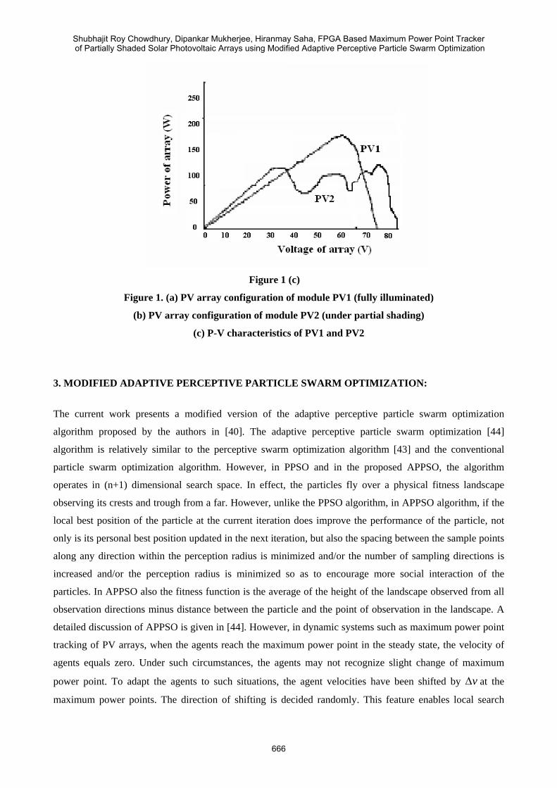
Figure 1 (c)
Figure 1. (a) PV array configuration of module PV1 (fully illuminated)
(b) PV array configuration of module PV2 (under partial shading)
(c) P-V characteristics of PV1 and PV2
3. MODIFIED ADAPTIVE PERCEPTIVE PARTICLE SWARM OPTIMIZATION:
The current work presents a modified version of the adaptive perceptive particle swarm optimization
algorithm proposed by the authors in [40]. The adaptive perceptive particle swarm optimization [44]
algorithm is relatively similar to the perceptive swarm optimization algorithm [43] and the conventional
particle swarm optimization algorithm. However, in PPSO and in the proposed APPSO, the algorithm
operates in (n+1) dimensional search space. In effect, the particles fly over a physical fitness landscape
observing its crests and trough from a far. However, unlike the PPSO algorithm, in APPSO algorithm, if the
local best position of the particle at the current iteration does improve the performance of the particle, not
only is its personal best position updated in the next iteration, but also the spacing between the sample points
along any direction within the perception radius is minimized and/or the number of sampling directions is
increased and/or the perception radius is minimized so as to encourage more social interaction of the
particles. In APPSO also the fitness function is the average of the height of the landscape observed from all
observation directions minus distance between the particle and the point of observation in the landscape. A
detailed discussion of APPSO is given in [44]. However, in dynamic systems such as maximum power point
tracking of PV arrays, when the agents reach the maximum power point in the steady state, the velocity of
agents equals zero. Under such circumstances, the agents may not recognize slight change of maximum
power point. To adapt the agents to such situations, the agent velocities have been shifted by vΔ at the
maximum power points. The direction of shifting is decided randomly. This feature enables local search
Shubhajit Roy Chowdhury, Dipankar Mukherjee, Hiranmay Saha, FPGA Based Maximum Power Point Tracker of Partially Shaded Solar Photovoltaic Arrays using Modified Adaptive Perceptive Particle Swarm Optimization
666

around the maximum power point and enables the photovoltaic system to sense and track quickly to the
slight variations in the shading pattern around the maximum power point.
4. APPLICATION OF APPSO TO MPPT TRACKING OF PV ARRAY
The current work applies the APPSO algorithm to the maximum power point tracking of PV arrays. In case
of constant bus voltage applications only one current sensor is sufficient for tracking the maximum power
from several individual PV modules. It is called multidimensional MPPT control. The terminal voltage of the
individual PV systems are grouped and represented in the form of N-dimensional row vector indicating the
position vector of the particles as kx
],,,[ 21k
Nkkk VVVx …= ……………...……………………………………………………………...………(1)
where N is the size of the row vector and indicates the number of PV strings.
The velocity vector v can be represented as:
],,,[ 1122
111
−−− −−−= kN
kN
kkkkk VVVVVVv … ………………………………………………………....…(2)
The landscape function is the generated power that is spanning over a N+1 dimensional search space. The
output vector changes and measures the power )( kxP .
Nk
Nkkk IVIVIVxP +++= 2211)( ………………………………………………………………….…...(3)
where refers to the string currents in the strings with terminal voltages . The
output voltage vector changes in the following order .
NIII ,,, 21 … kN
kk VVV ,,, 21 …kN
kkk xxxx →→→→→ 321
For obtaining the currents, the circuit model of a PV cell is considered. The circuit model of a PV cell is
shown in figure 2. The shunt resistance is ignored for the sake of simplicity which is good enough for fairly
accurate models.
Figure 2. Circuit model of a PV cell
The current equations which describe the I-V characteristics of the cell are given in [4] as:
INTERNATIONAL JOURNAL ON SMART SENSING AND INTELLIGENT SYSTEMS, VOL. 2, NO. 4, DECEMBER 2009
667

)11........(....................................................................................................)(/(
)10........(............................................................................................................../1/
)9....(............................................................................................................../(
)8(....................................................................................................)/(
)7........(..........................................................................................)........./()(
)6.......(............................................................................................................../.
)5.......(....................................................................................................))........(1()4.....(....................................................................................................).........1(
1)1(
1
1)1(
11
1
1
12
,11
1
/1)(0
)1/)()(0
)/1/1).(/(/31)(00
12)()(0
)()()(
10)(
/)(0
nkTqVTV
VVS
nkTqVTSCT
TTnkqVnT
TSCTSC
nomTSCTL
TLL
nkTIRVqL
TOC
OC
TOC
g
nom
S
enkTqIX
XdIdVR
eII
eTTII
TTIIK
GIGI
TTKIIeIII
=
−−=
=
=
−−=
=
−+=−−=
−
−−
+
where symbols have their usual meanings.
When the agents reach the maximum power point in the steady state, the velocity of agents equals zero.
Under such circumstances, the agents may not recognize slight change of maximum power point. To adapt
the agents to such situations, the agent velocities have been shifted by vΔ at the maximum power points. The
direction of shifting is decided randomly. This feature enables local search around the maximum power point
and enables the photovoltaic system to sense and track quickly to the slight variations in the shading pattern
around the maximum power point. The modified adaptive perceptive particle swarm optimization algorithm
will be abbreviated as MAPPSO.
4.1 VHDL SIMULATION AND RESULTS
For simulation, we consider two strings of PV modules. Module PV1 is totally illuminated by solar radiation.
However, module PV2 is partly under shade. Hence, in the context of the present problem M=2. N is set to 5.
The optimal parameters of the two modules have been taken same as in [42].
The particle velocities are initialized randomly as shown in table 1: .
Table 1. Initialization of particle velocities
Agent V1 [V] V2 [V]
1 0.2Vop 0.3Vop
2 0.5Vop 0.4Vop
3 0.6Vop 0.1Vop
4 0.8Vop 0.7Vop
5 0.9Vop 0.4Vop
where Vop refers to the open circuit voltage of the array.
Using the 8 variations of APPSO given in [40] 8 variations of MAPPSO, as well as PSO and GA, we have
got the results of Maximum Power Point Tracking as shown in table 2:
Shubhajit Roy Chowdhury, Dipankar Mukherjee, Hiranmay Saha, FPGA Based Maximum Power Point Tracker of Partially Shaded Solar Photovoltaic Arrays using Modified Adaptive Perceptive Particle Swarm Optimization
668

Table 2. Results of Maximum Power Point Tracking obtained using different techniques
PV1 Voltage PV2 Voltage Power Algorithm
Optimal MPPT
PV1
Current Optimal MPPT
PV2
Current Optimal MPPT Efficiency
APPSO1 45.7V 4.13A 46.8V 4.06A 379W 96.93%
APPSO2 45.8V 4.12A 46.9V 4.04A 378W 96.67%
APPSO3 45.9V 4.16A 46.3V 4.12A 382W 97.70%
APPSO4 45.4V 4.18A 46.3V 4.11A 381W 97.44%
APPSO5 45.5V 4.14A 46.5V 4.09A 379W 96.93%
APPSO6 45.6V 4.13A 46.9V 4.06A 378W 96.67%
APPSO7 45.5V 4.14A 46.2V 4.08A 377W 96.41%
APPSO8 45.7V 4.16A 46.9V 4.06A 381W 97.44%
MAPPSO1 45.7V 4.13A 46.7V 4.05A 378W 96.67%
MAPPSO2 45.8V 4.12A 46.8V 4.04A 378W 96.67%
MAPPSO3 45.9V 4.16A 46.4V 4.13A 383W 97.95%
MAPPSO4 45.4V 4.18A 46.4V 4.11A 380W 97.18%
MAPPSO5 45.5V 4.14A 46.3V 4.08A 377W 96.48%
MAPPSO6 45.6V 4.13A 46.8V 4.06A 378W 96.67%
MAPPSO7 45.5V 4.14A 46.3V 4.07A 377W 96.41%
MAPPSO8 45.7V 4.16A 46.9V 4.05A 380W 97.18%
PSO 46.1V 4.06A 47.1V 4.03A 377W 96.41%
GA
45V
46.2V 4.01A
45V
46.9V 4.07A
391W
376W 96.16%
An analysis of table 2 reveals that MAPPSO3 yields the Maximum Power Point that is closest to the global
optimal Maximum Power Point. Moreover, we see that while using PSO, the global optimal MPP is reached
with 96.41% accuracy, the MPP can be reached with 97.7% accuracy using APPSO algorithm and MPP can
be reached with 97.95% using MAPPSO algorithm.
5. FPGA BASED PROPOSED HARDWARE FOR MPPT:
Based on the proposed technique, a two stage power electronic grid connected system architecture has been
proposed as shown in figure 3.
Figure 3: System configuration for grid connected PV-based system
INTERNATIONAL JOURNAL ON SMART SENSING AND INTELLIGENT SYSTEMS, VOL. 2, NO. 4, DECEMBER 2009
669

The system comprises of a boost type dc-dc converter and an inverter to feed the power generated by PV
array to the grid and grid connected loads. The MPPT control algorithm based on MAPPSO has been
realized on a Cyclone EP1C6Q240C8 FPGA chip. The DC-DC converter can be realized on TMS320F280X
DC-DC buck converter. For converting the analog current being sensed into the digital form to be
understood by the FPGA, an A/D converter ADS1208 has been used. The technology schematic of the
MPPT controller as realized on the FPGA is shown figure 4.
CLK
DATAA
DATAB
DATAC
DATAD
ENA
REGOUT
LCELL (5F0C)
CLK
DATAA
DATAC
DATAD
ENA
REGOUT
LCELL (AAF0)
CLK
DATAA
DATAB
DATAD
ENA
SYNCH_DATA
COMBOUT
LCELL (BBC0)
CLK
DATAA
DATAB
DATAD
ENA
SYNCH_DATA
COMBOUT
LCELL (F388)
CLK
DATAA
DATAB
DATAD
ENA
SYNCH_DATA
COMBOUT
LCELL (E6A2)
CIN
CIN0
CIN1
CLK
ENA
COMBOUT
REGOUT
LCELL (0F0F)
CIN
CIN0
CIN1
CLK
ENA
COMBOUT
REGOUT
LCELL (0F0F)
!ACLR
CLK
DATAD
SYNCH_DATA
COMBOUT
REGOUT
LCELL (F000)
!ACLR
CIN
CIN0
CIN1
CLK
DATAB
COUT0
COUT1
REGOUT
LCELL (3C3C)
!ACLR
CLK
DATAD
SYNCH_DATA
COMBOUT
REGOUT
LCELL (F000)
!ACLR
CIN
CLK
DATAB
COUT0
COUT1
REGOUT
LCELL (C3C3)
!ACLR
CIN
CIN0
CIN1
CLK
DATAA
REGOUT
LCELL (A5A5)
DATAA
DATADCOMBOUT
LCELL (AA00)
!ACLR
CLK
DATAD
SYNCH_DATA
COMBOUT
REGOUT
LCELL (F000)
!ACLR
CLK
DATAD
SYNCH_DATA
COMBOUT
REGOUT
LCELL (F000)
DATAA
DATAC
DATAD
COMBOUT
LCELL (AAA0)
!ACLR
CLK
DATAD
SYNCH_DATA
COMBOUT
REGOUT
LCELL (F000)
!ACLR
CIN
CIN0
CIN1
CLK
DATAB
COUT
REGOUT
LCELL (3C3C)
!ACLR
CIN
CIN0
CIN1
CLK
DATAA
COUT0
COUT1
REGOUT
LCELL (A5A5)
DATAA
DATAB
DATAC
DATAD
COMBOUT
LCELL (8088)
DATAA
DATAB
DATAC
DATAD
COMBOUT
LCELL (A080)
!ACLR
CLK
DATAD
SYNCH_DATA
COMBOUT
REGOUT
LCELL (F000)
!ACLR
CIN
CIN0
CIN1
CLK
DATAA
COUT0
COUT1
REGOUT
LCELL (5A5A)
!ACLR
CLK
DATAA
DATAB
DATAD
SYNCH_DATA
COMBOUT
REGOUT
LCELL (22A0)
DATAA
DATAC
DATAD
COMBOUT
LCELL (00A0)
!ACLR
CIN
CIN0
CIN1
CLK
DATAB
COUT0
COUT1
REGOUT
LCELL (C3C3)
!ACLR
CLK
DATAA
DATAB
DATAD
SYNCH_DATA
COMBOUT
REGOUT
LCELL (F0B0)
!ACLR
CLK
SYNCH_DATA
REGOUT
LCELL (0000)
!ACLR
CLK
DATAA
DATAD
SYNCH_DATA
COMBOUT
REGOUT
LCELL (50F0)
!ACLR
CLK
DATAD
SYNCH_DATA
COMBOUT
REGOUT
LCELL (00F0)
CLK
DATAA
DATAC
DATAD
ENA
REGOUT
LCELL (505A)
!ACLR
CLK
DATAA
DATAB
DATAC
DATAD
REGOUT
LCELL (ECA0)
!ACLR
CLK
DATAA
DATAB
DATAC
DATAD
REGOUT
LCELL (F222)
DATAA
DATAB
DATAC
DATAD
COMBOUT
LCELL (8000)
CLK
DATAA
DATAB
DATAC
DATAD
ENA
REGOUT
LCELL (F222)
CLK
DATAB
DATAC
DATAD
ENA
REGOUT
LCELL (0CFC)
!ACLR
CLK
DATAA
DATAB
DATAC
DATAD
REGOUT
LCELL (ECA0)
!ACLR
CLK
DATAA
DATAD
REGOUT
LCELL (AA00)
DATAA
DATAB
DATAC
DATAD
COMBOUT
LCELL (8000)
DATAA
DATADCOMBOUT
LCELL (AA00)
!ACLR
CLK
DATAA
DATAB
DATAD
SYNCH_DATA
COMBOUT
REGOUT
LCELL (FF02)
DATAA
DATAB
DATAC
DATAD
COMBOUT
LCELL (E000)
!ACLR
CLK
DATAB
SYNCH_DATA
COMBOUT
REGOUT
LCELL (3030)
!ACLR
CLK
DATAD
SYNCH_DATA
COMBOUT
REGOUT
LCELL (F000)
DATAA
DATAC
DATAD
COMBOUT
LCELL (FA00)!ACLR
CLK
DATAD
SYNCH_DATA
COMBOUT
REGOUT
LCELL (F000)
DATAA
DATAB
DATAC
DATAD
COMBOUT
LCELL (2700)
CLK
DATAA
DATAB
DATAC
DATAD
ENA
REGOUT
LCELL (BBA0)
CLK
DATAA
DATAB
DATAC
DATAD
ENA
REGOUT
LCELL (FFA8)
CLK
DATAA
DATAB
DATAC
DATAD
ENA
REGOUT
LCELL (FEAA)
Selector39~79_COMBOUT
state.init_REGOUT
lpm_divide:Div15_add_sub_cella[2]~27lpm_divide:Div12_add_sub_cella[2]~27
prouh[7]_REGOUT
probh[7]_REGOUTresult[0]~1435_COMBOUT
progl[7]_COMBOUTlpm_divide:Div5_add_sub_cella[2]~27
progm[7]_COMBOUT
prodl[7]_REGOUTresult[0]~1539_COMBOUT
result~1496_COMBOUTlpm_divide:Div14_add_sub_cella[2]~27
result[0]~1443_COMBOUTresult[0]~1432_COMBOUT
lpm_divide:Div13_add_sub_cella[2]~27
prosl[7]_COMBOUT
lpm_divide:Div19_add_sub_cella[3]~72lpm_divide:Div19_add_sub_cella[3]~68
lpm_divide:Div19_add_sub_cella[3]~68COUT1_86
result2[3]~0_COMBOUT
result2[1]_COMBOUTresult2[1]_REGOUT
lpm_divide:Div19_add_sub_cella[3]~68lpm_divide:Div19_add_sub_cella[3]~70
lpm_divide:Div19_add_sub_cella[3]~70COUT1_86
result2[2]_COMBOUTresult2[2]_REGOUT
state.compute_3_COMBOUTstate.compute_3_REGOUT
count[18]_REGOUT
state.sw_sel1_REGOUT
state.data_sel_COMBOUT
count[19]_REGOUT
state.compute_0_REGOUTprobm[11]~4_COMBOUT
state.compute_1_COMBOUTstate.compute_1_REGOUT
state.compute_5_COMBOUT
prouh[15]~100_COMBOUT
state.compute_8_COMBOUT
count[9]_COUT
disp0[0]~2483_COMBOUT
disp0[6]~2478_COMBOUT
disp0[0]~2484_COMBOUT
Equal13~137_COMBOUTdisp2[0]~1315_COMBOUT
disp0[4]~2480_COMBOUT
disp2[0]~1316_COMBOUT
state.compare_COMBOUT
LessThan68~176_COMBOUT
state.res_sel_1_REGOUT
state.compute_4_COMBOUT
state.compute_4_REGOUT
disp2~1309_COMBOUT
result[11]~1450_COMBOUT
count[12]_COUT0count[12]_COUT1
result1[0]_REGOUTresult1[1]_REGOUTresult1[2]_REGOUT
state.compute_2_COMBOUT
state.compute_2_REGOUT
state.critical_REGOUT
j[0]_REGOUTj[1]_REGOUT
state.compute_sp_REGOUT
state.compute_dp_COMBOUTstate.compute_dp_REGOUT
Equal32~69_COMBOUT
state.res_disp_COMBOUT
state.res_disp_REGOUT
state.sw_sel2_REGOUT
i[0]_REGOUT
state.sp_sel_1_REGOUTSelector79~68_COMBOUT
state~1328_COMBOUT
Equal0~71_COMBOUT
state.sp_sel_REGOUT
Selector68~69_COMBOUTSelector68~70_COMBOUT
state.ht_sel_1_REGOUT
state.compute_REGOUT
b[3][0]~16_COMBOUT
WideOr1~14_COMBOUTAdd1~503_COMBOUTstate.delay1_REGOUT
cnt2[14]_REGOUT
Selector72~44_COMBOUT
cnt2[0]_REGOUT
Selector61~41_COMBOUTSelector76~39_COMBOUT
state.wt_sel_1_REGOUT
state.wt_sel_REGOUT
state.pb_sel2_REGOUTpb_s_REGOUT
state.delay_REGOUT
state.compute_ht_REGOUT
b1[3][0]~16_COMBOUT
data1[0]~274_COMBOUT
data1[0]~275_COMBOUT
WideOr0~4_COMBOUTstate.htwt_sel_REGOUT
disp0[4]~2487_COMBOUTstate.hold_REGOUT
state.htwt_sel_1_COMBOUTstate.htwt_sel_1_REGOUT
cnt[1]~1163_COMBOUTSelector127~280_COMBOUT
WideOr0~5_COMBOUT
cnt[0]~1164_COMBOUT
Equal9~30_COMBOUT
state.display_COMBOUT
state.display_REGOUT
state.compute_6_COMBOUT
probh[15]~100_COMBOUT
state.compute_7_COMBOUT
state.compute_7_REGOUT
WideOr12~15_COMBOUT
data0[0]~105_COMBOUT
Equal15~97_COMBOUTdp3_REGOUT
Selector137~411_COMBOUTSelector137~409_COMBOUT
disp3[3]_REGOUT
Selector56~544_COMBOUTSelector56~547_COMBOUT
Selector138~248_COMBOUTdp1_REGOUT
mc~reg0
clk
rst
mc
prouh[7]
prosm[7]prosl[7]
result2[1]
result2[2]
count[18]
count[15]
count[19]
probm[11]~4
state.compute_1
state.compute_5
prouh[15]~100
state.compute_8
count[14]
count[17]
disp2[0]~1316
state.compare
result[11]~1450
count[13]
state.compute_2
state.critical
state.res_disp
state.sp_sel
state.ht_sel_1
b[3][0]~16
cnt2[14]
cnt2[0]
state.wt_sel
state.delay
b1[3][0]~16
data1[0]~275
state.htwt_sel_1
cnt[0]~1164
state.display
state.compute_6
probh[15]~100
state.compute_7
data0[0]~105
dp3
disp3[3]
dp1
state.compute_dp
state.compute_4
state.data_sel
i[0]
disp0[0]~2484
progm[7]
count[16]
state.compute_3
Figure 4. Technology schematic of the FPGA based MPPT controller
Shubhajit Roy Chowdhury, Dipankar Mukherjee, Hiranmay Saha, FPGA Based Maximum Power Point Tracker of Partially Shaded Solar Photovoltaic Arrays using Modified Adaptive Perceptive Particle Swarm Optimization
670

The value of the maximum power point is displayed on LED 7 segment displays. The whole circuit is shown
in figure 5.
Figure 5. Control circuit for the PV array
The technology schematic shows how the look up tables (LUTs) in the FPGA chip have allocated and the
connections between the different LUTs to realize the system on the FPGA. Table 3 shows the resource
utilization summary of the MPPT controller.
Table 3. Resource utilization summary of the MPPT controller
Resource Usage
Combinational logic elements with no register 4382
Registers 848
Combinational logic elements with a register 285
Total logic elements 5967 (out of 5980)
Total logic cells in carry chains 2354
I/O pins 27
Maximum fan out node Clk
Maximum fan out 1164
Total fan out 15238
Average fan out 2.87
The resource utilization summary shows the number of different types of blocks realized on the FPGA for
realizing the particular application. From table 1, it is clear that only 13 logic elements in the FPGA have
been wasted in achieving an FPGA based implementation of the system. The FPGA based implementation of
the system is very attractive owing to the fact that FPGAs are reconfigurable and becoming economical and
faster day by day.
INTERNATIONAL JOURNAL ON SMART SENSING AND INTELLIGENT SYSTEMS, VOL. 2, NO. 4, DECEMBER 2009
671

6. CONCLUSION:
A novel MPPT algorithm using modified APPSO technique was proposed to control several PV arrays with
one pair of voltage and current sensors. The APPSO algorithm has been suitably modified to suit to the slight
changes in the maximum power point at around the maximum power point. The developed algorithm is
simple and also reduces cost in the data acquisition system. The proposed technique indicates that the MPP
can be tracked with greater accuracy (97.95%) using modified APPSO algorithm than that is possible with
the PSO or GA or even APPSO algorithm. The MPPT controller has been realized on an FPGA. The
implementation of the algorithm on a reconfigurable architecture like FPGA ensures hardware based
flexibility in the motion dynamics presented by APPSO. Based on the proposed technique, a two stage power
electronic grid connected system configuration has been proposed. Compared to PSO that track to the MPP
under partial shading conditions and reaches the MPP with 96.41% accuracy, the APPSO can track to the
MPP with 97.95% accuracy.
7. REFERENCES
[1] E. Koutroulis, K. Kalaitzakis, and N. C. Voulgaris, “Development of a microcontroller-based
photovoltaic maximum power point tracking control system,” IEEE Transactions on Power
Electronics, vol. 16, no. 1, pp. 46–54, Jan. 2001.
[2] K. H. Hussein and I. Muta, “Maximum photovoltaic power tracking: An algorithm for rapidly changing
atmospheric conditions,” Proceedings of IEE Generation, Transmission and Distribution, vol. 142, no.
1, pp. 59–64, Jan. 1995.
[3] S. Jain and V.Agarwal, “A new algorithm for rapid tracking of approximate maximum power point in
photovoltaics systems,” IEEE Power Electronics Letters, vol. 2, no. 1, pp. 16–19, Mar. 2004.
[4] G. Walker, “Evaluating MPPT converter topologies using a MATLAB PV model”, Journal of
Electrical and Electronics Engineering, Australia, Vol. 21, No.1, pp. 16-19, Mar. 2001.
[5] M.C. Alonso-Gracia, J.M. Ruiz, F. Chenlo, “Experimental study of mismatch and shading effects in the
I–V characteristic of a photovoltaic module”, Solar Energy Materials and Solar Cells, Vol. 90, No. 3,
pp. 329-340, Feb. 2006.
[6] H. Kawamura, K. Naka, N. Yonekura, S. Yamanaka, H. Ohno, K. Naito, “Simulation of the I-V
characteristics of a PV module with PV shaded PV cells”, Solar Energy Materials and Solar Cells, Vol.
75, No. 3-4, pp. 613-621, Feb. 2003.
[7] M. Shechter, J. Appelbaum and G. Yekutieli, “Quality factor of solar cell arrays”, Solar Cells, 9(1983)
295-309.
[8] H. Saha, G. Bhattacharya, D. Mukherjee, “Mismatch losses in series combinations of silicon solar cell
modules”, Solar Cells, 25(1988) 143-153.
[9] T.J. Lambarski, D.L. Kadle, C.B. Rogers, “Effects of cell sorting and module matching on array
output”, Proceedings of 15th Photovoltaic Specialist Conference, pp. 841, Florida, New York, 1981.
Shubhajit Roy Chowdhury, Dipankar Mukherjee, Hiranmay Saha, FPGA Based Maximum Power Point Tracker of Partially Shaded Solar Photovoltaic Arrays using Modified Adaptive Perceptive Particle Swarm Optimization
672

[10] E.C. Kern, E.M. Gulachenski, G.A. Kern, “Cloud effects on distributed photovoltaic generation:
Slow transients at the Gardner, Masachusetts photovoltaic experiment”, IEEE Transactions on Energy
Conversion, Vol. 4, No. 2, pp. 184-190, Jun. 1989.
[11] F. Giraud, Z. Salameh, “Analysis of the effects of a passing cloud on a grid interactive photovoltaic
system with battery storage using neural networks”, IEEE Transactions on Energy Conversion, Vol. 14,
No. 4, pp. 1572-1577, Dec. 1999.
[12] M.G. Jahoori, M.M. Saied, A.R. Hanafy, “A contribution to the simulation and design optimization
of photovoltaic system”, IEEE Transactions on Energy Conversion, Vol. 6, No. 3, pp. 401-406, Sep.
1991.
[13] O. Wasynzuck, “Dynamic behavior of a class of photovoltaic power systems”, IEEE Transactions on
Power Apparatus and Systems, Vol. PAS-102, No. 9, pp. 3031-3037, Sep. 1983.
[14] P. Huynh, B.H. Cho, “Design and analysis of a microprocessor controlled peak power tracking
system”, IEEE Transactions on Aerospace Electronic Systems, Vol. AES-32, No. 1, pp. 182-190, Jan
1996.
[15] K. Hussein, I. Muta, T. Hoshino, M. Osakada, “Maximum photovoltaic power tracking: an algorithm
for rapidly changing atmospheric conditions”, IEE Proceedings of Generation, Transmission and
Distribution, Vol. 142, No. 1, pp. 59-64, Jan. 1995.
[16] Shantharama Rai C. et al, “A novel technique for Photovoltaic Maximum Power Point Tracking
System”, in Proceedings of EPE 2005, No. 286, 2005.
[17] N. Kasa, T. Lida, L. Chen, “Flyback Inverter controlled by Sensorless Current MPPT for Photovoltaic
Power System”, IEEE Transactions on Industrial Electronics, Vol. 52, No. 4, pp. 1145-1152, Aug.
2005.
[18] N. Femia et al, “Optimization of perturb and observe maximum power point tracking method”, IEEE
Transaction on Power Electronics, Vol. 20, No. 4, pp. 963-973, 2005.
[19] M. Veerachary, “Power tracking for non linear PV sources with Coupled Inductor SEPIC Converter”,
IEEE Transactions on Aerospace and Electronic Systems, Vol. 41(3), pp. 1019-1029, 2005.
[20] Joung Hu Park et al, “Dual module based Maximum Power Point tracking control of Photovoltaic
systems”, IEEE Transactions on Industrial Electronics, Vol. 53, No. 4, pp. 1036-47, 2006.
[21] E.V. Solodovnik, S. Liu, and R.A. Dougal, “Power Controller Design for Maximum Power Point
Tracking in Solar Insolations”, Vol. 19, No. 5, pp. 1295-1304, Sept. 2004.
[22] S. Maity, “MPPT tracking of solar cells”, P.G. dissertation, Department of Electronics and
Telecommunication, Bengal Engineering and Science University, Shibpur, 2005.
[23] M. Bodur and M. Ermis, “Maximum Power Point Tracking for Low Power Photovoltaic Solar Panels”,
in Proceedings of 7th Mediterranean Electrotechnical Conference, 1994, pp. 758-761.
[24] K. Kobayashi, I. Takano and Y. Sawada, “A study on a two stage maximum power point tracking
control of a photovoltaic system under partially shaded insolation conditions”, in Proceedings of IEEE
Power Engineering Society General Meeting 2003, Vol. 4, 2003.
INTERNATIONAL JOURNAL ON SMART SENSING AND INTELLIGENT SYSTEMS, VOL. 2, NO. 4, DECEMBER 2009
673

[25] A. Kajihara and T. Harakawa, “On considerations of equivalent model about PV cell under partial
shading” Proceedings of Japan Industry Applications Society Conference IEE of Japan, Vol. 1, No. 71,
pp. I 289-292, Fukui, 2005.
[26] M.A. Abido, “Optimal design of power system stabilizers using particle swarm optimization”, IEEE
Transactions on Energy Conversion Vol. 17 No. 3, pp. 406–413, 2002.
[27] D.K. Agrafiotis and W. Cedeno, “Feature selection for structure–activity correlation using binary
particle swarms”, Journal of Medicinal Chemistry Vol. 45 No. 5, pp. 1098–1107, 2002.
[28] C. Fourie and A.A. Groenwold, “The particle swarm optimization algorithm in size and shape
optimization”, Structural Multidisciplinary Optimization Vol. 23, pp. 259–267, 2002.
[29] C.O. Ourique, E.C. Biscaia and J. Carlos Pinto, “The use of particle swarm optimization for dynamical
analysis in chemical processes”, Computers and Chemical Engineering Vol. 26, pp. 1783–1793, 2002.
[30] K.E. Parsopoulos and M.N. Vrahatis, “Recent approaches to global optimization problems through
particle swarm optimization”, Natural Computing Vol. 1 No. 2–3, pp. 235–306, 2002.
[31] K.E. Parsopoulos and M.N. Vrahatis, “On the computation of all global minimizers through particle
swarm optimization”, IEEE Transactions on Evolutionary Computation Vol. 8 No. 3, pp. 211–224,
2004.
[32] K.E. Parsopoulos, E.I. Papageorgiou, P.P. Groumpos and M.N. Vrahatis, “Evolutionary computation
techniques for optimizing fuzzy cognitive maps in radiation therapy systems”, Lecture Notes in
Computer Science Vol. 3102, pp. 402–413, 2004.
[33] K.E. Parsopoulos and M.N. Vrahatis, “Unified particle swarm optimization in dynamic environments”,
Lecture Notes in Computer Science Vol. 3449, pp. 590–599, 2005.
[34] T. Ray and K.M. Liew, “A swarm metaphor for multiobjective design optimization”, Engineering
Optimization Vol. 34 No. 2, pp. 141–153, 2002.
[35] K.E. Parsopoulos and M.N. Vrahatis, “UPSO: A unified particle swarm optimization scheme”,
Proceedings of the International Conference of Computational Methods in Sciences and Engineering
ICCMSE 2004, Lecture Series on Computer and Computational Sciences Vol. 1, VSP International
Science Publishers, Zeist, The Netherlands, pp. 868–873, 2004.
[36] K.E. Parsopoulos and M.N. Vrahatis, “Parameter selection and adaptation in Unified Particle Swarm
Optimization”, Mathematical and Computer Modelling, Vol. 46, No. 1-2, pp.198-213, 2007.
[37] R. Kathiravan and R. Ganguli, “Strength design of composite beam using gradient and particle swarm
optimization”, Composite Structures, Vol. 81, No. 4, pp. 471-479, 2007.
[38] S. Suresh, P.B. Sujit and A.K. Rao, “Particle swarm optimization approach for multi-objective
composite box-beam design”, Composite Structures, Vol. 81, No. 4, pp. 598-605, 2007.
[39] H. Feng, C. Chen, F. Ye, “Evolutionary fuzzy particle optimization vector quantization learning in
image compression”, Expert Systems with Applications, Vol. 32, pp. 213-222, 2007.
[40] E. Bonabeau, M. Dorigo and G. Théraulaz, From Natural to Artificial Swarm Intelligence, Oxford
University Press, New York, 1999.
Shubhajit Roy Chowdhury, Dipankar Mukherjee, Hiranmay Saha, FPGA Based Maximum Power Point Tracker of Partially Shaded Solar Photovoltaic Arrays using Modified Adaptive Perceptive Particle Swarm Optimization
674

[41] J. Kennedy and R.C. Eberhart, Swarm Intelligence, Morgan Kaufmann, 2001.
[42] M. Miyatake, F. Toriumi, T. Endo and N. Fuiji, “A novel Maximum Power Point Tracker controlling
several converters connected to Photovoltaic arrays with Particle Swarm Optimization”, Proceedings of
European Conference on Power Electronics and Applications 2007, pp. 1-10, 2007.
[43] B. Kaewkamnerdpong and P. Bentley, “Perceptive Particle Swarm Optimization: An investigation”,
Proceedings of IEEE Symposium on Swarm Intelligence, IEEE CS Press, Vol. 1, No. 1, pp 8-10, 2005.
[44] S. Roy Chowdhury, D. Chakrabarti, H. Saha, “Medical Diagnosis using Adaptive Perceptive Particle
Swarm Optimization and its hardware realization using Field Programmable Gate Array”, Journal of
Medical Systems, Vol. 33, No. 6, pp. 447-465, 2009.
[45] S. Roy Chowdhury, H. Saha, “Maximum Powerpoint Tracking of Solar Photovoltaic Arrays using
Adaptive Perceptive Particle Swarm Optimization Technique”, 18th Photovoltaic Science Exhibition
and Conference, PVSEC 18, Kolkata, January 19-23, 2009.
INTERNATIONAL JOURNAL ON SMART SENSING AND INTELLIGENT SYSTEMS, VOL. 2, NO. 4, DECEMBER 2009
675