fox thermal instruments, inc. · fox thermal instruments believes that the information provided...
TRANSCRIPT

104488Rev. E
Model FT3
Fox Thermal Instruments, Inc.
www.foxthermalinstruments.com | 399 Reservation Road Marina, CA. 93933
THERMAL MASS FLOW METER & TEMPERATURE TRANSMITTER

F O X I S I S O 9 0 0 1 C E R T I F I E D
All Fox Manuals and software available in English only.
Fox FT3 Manuals:• Fox FT3 Calibration Validation User's Guide• Fox FT3 RS485 Modbus Manual• Fox FT3 HART Manual• Fox FT3 View™
Notice
Model FT3FO
X T
HER
MAL IN
STR
UM
EN
TS
2
This publication must be read in its entirety before performing any operation. Failureto understand and follow these instructions could result in serious personal injury
and/or damage to the equipment. Should this equipment require repair or adjustmentbeyond the procedures given herein, contact the factory at:
FOX THERMAL INSTRUMENTS, INC.399 RESERVATION ROAD
MARINA, CA 93933TELEPHONE: 831-384-4300
FAX: 831-337-5787EMAIL: [email protected]
Download Technical Data Sheets from our website:www.foxthermalinstruments.com
Fox Thermal Instruments believes that the information provided herein is accurate; however, be advised that the information contained herein is NOT a guarantee for satisfactory results. Specifically, this information is neither a warranty nor
guarantee, expressed or implied, regarding performance, merchantability, fitness, or any other matter with respect to the products; nor recommendation for the use
of the product/process information in conflict with any patent. Please note that Fox Thermal Instruments, Inc. reserves the right to change and/or improve the product
design and specification without notice.

Table Of Contents
Model FT3TAB
LE O
F C
ON
TEN
TS
1. Introduction Page 4
2. Installation (Mechanical) Page 8
a. Insertion Type Page 9
b. Inline Type Page 13
3. Wiring (Electrical) Page 15
a. General Page 16
b. Input Power Page 17
c. Signal Wiring Page 19
d. Alarm Wiring Page 21
e. Remote Switch Page 22
f. Remote Wiring Page 23
4. Operation (Standard Operation) Page 26
a. Start Up Page 25
b. Display Screens Page 26
c. Engineering Screens Page 27
d. Programming Page 28
e. Menu Trees Page 56
5. Maintenance Page 63
a. Troubleshooting Page 67
7. Appendices Page 72
a. Specifications Page 72
b. Agency Approvals Page 75
c. FT3 with 2 Gas Curves Page 76
d. Dimensions Page 80
e. Installation Variations Page 88
f. Warranty Page 90
g. Returning your meter Page 92
8. Glossary of Terms and Abbreviations Page 94
9. Index Page 96
3

Thank you for purchasing the Model FT3 Thermal Gas Mass Flow Meter and Temperature Transmitter from Fox Thermal Instruments. The Model FT3 is one of the most technically advanced flow meters in the world. Extensive engineering effort has been invested to deliver advanced features, accuracy measurement performance and outstanding reliability.
This Instruction Manual contains the electrical and mechanical installation instructions as well as details for programming, maintaining and troubleshooting the meter.
This manual is divided into the following sections: Introduction, Installation, Wiring, Operation, Maintenance, Troubleshooting, Appendices, Glossary and Index. Theory of OperationThe Model FT3 is an innovative Thermal Mass Gas Flow Meter and Temperature Transmitter. It is microprocessor-based and field programmable. The FT3 thermal sensor operates on the law that gases absorb heat. A heated sensor placed in an air or gas stream transfers heat in proportion to the stream’s mass velocity. There are two sensor elements connected to a balanced bridge circuit. One sensor element detects the gas temperature and a second element is maintained at a constant temperature above the gas temperature. The energy applied to the heated sensor to maintain a constant temperature differential (constant ∆ T) is directly proportional to the mass flow velocity. The FT3 flow meter maintains accurate flow measurement over a large temperature and pressure range.
Mass FlowThe Model FT3 measures mass flow; an advantage over other flow meters which measure volumetric flow rate. Volumetric flow is incomplete because temperature and pressure are unknown and must be measured separately. For example, the mass flow of a gas depends on its temperature and pressure. As temperature and pressure changes, the gas volume changes but not its mass. Therefore a device measuring mass flow is independent of temperature and pressure. The Model FT3 provides a direct measurement of gas flow in Mass units (kg/hr, lb/hr), standard units (SCFM, SLPM) or normal units (NM3/hr, NLPM) with no additional temperature or pressure measurements required.
4
Introduction
Scope
Model FT3IN
TR
OD
UC
TIO
N
Calibration Validation
I/O Description
Product Description
Mass Flow
Welcome
Flow Calibration
Calibration ValidationFox has developed a method to validate the calibration of the flow meter in the field. This method is called Calibration Validation and it is made up of two distinct tests: CAL-V™ and Zero CAL-CHECK™. The goal of Calibration Validation is to provide operators with the ability to verify that the meter is capturing accurate data at scheduled recalibration times - or at any time - instead of sending the meter back to the factory for recalibration.
By performing CAL-V™ in the field, operators can verify that the meter is running accurately by testing the functionality of the sensor and its associated signal processing circuitry. This test can be done in the pipe and in normal processing conditions. The second test, Zero CAL-CHECK™, ensures the effectiveness and sensibility of the sensor at a "no flow" condition.
Flow CalibrationThe Fox Calibration Lab maintains instrument calibration records on every flow meter. This data can also be accessed by a computer using FT3 View™ software within the instrument. Computer-generated calibration documents describe specific instrument details that can be sorted by serial number, tag number or customer purchase order.
Calibration files include details on process conditions, calibration fluid, line size and other information. All NIST-traceable equipment utilized for the calibration procedure is identified, as is the calibration history of all reference equipment.
In addition to the Calibration Certificate, a certified flow table that correlates current outputs with scaled units of flow is produced for each calibrated device.
I/O DescriptionThe FT3 features two galvanically isolated 4 to 20mA analog outputs: one isolated digital output that can be used for frequency or alarm, one programmable discrete input and a USB connection for communication with a computer. The first 4 to 20mA output is for flow rate. The second 4 to 20mA output can be configured either for flow rate or process gas temperature. Both 4 to 20mA outputs can be scaled by the user. The frequency output is
5
Introduction
Calibration Validation
I/O Description
Model FT3IN
TR
OD
UC
TIO
N
Flow Calibration

F1 F2 F3 F4
IR (infrared) Buttons
Display Window
Push Buttons
programmable to represent flow rate and can be scaled for maximum flow/maximum frequency, units-per-pulse or pulse-per-units. The maximum frequency is 100 Hz. An isolated 24VDC output power option is provided for use with these outputs. It can supply a 42mA maximum total load (do not use for other external devices).
FT3 View™ interfaces to the USB port and is a free Fox PC-based software program that displays flow meter readings and permits flow meter configuration. Industry standard communication options are available including HART or RS485 Modbus. Only one of these options can be provided in a single FT3 flow meter.
FT3 Optional Display and Configuration PanelThe configuration panel allows the user to change a variety of settings in the FT3. The display is 2 lines x 16 characters with 4 mechanical and 4 IR (infrared) buttons. The IR and mechanical (push) buttons perform the same function but the IR buttons can be used without opening the cover. The IR buttons can be calibrated (p. 54) for better operation in the field or disabled (p. 54) when the meter is used in snow or ice in order to avoid false key detection.
Fig. 1.1: FT3 Optional Display and Configuration Panel
6
Model FT3IN
TR
OD
UC
TIO
N
www.foxthermalinstruments.com
Introduction
Display

F1 F2 F3 F4
Standard I/O
4 to 20 mA Flow
Contact Input
4 to 20 mA Flow or Temperature
Frequency or Alarm
USB(Free FT3 View Software)
Outputs and Communications are Galvanically Isolated
Optional Digital Communications
HART
RS485 Modbus
24VDC Input Power100-240VAC Optional
Optional Display andCon�guration Panel
Standard Digital Communications
FT3 Functional DiagramAn optional on-board display is available to view flow rate, total flow, elapsed time, process gas temperature and alarms. The display is also used in conjunction with the Configuration Panel for field configuration of flow meter settings such as 4 to 20mA scaling, pulse output frequency scaling, pipe area, zero flow cutoff, flow filtering or damping, display configurations, diagnostics and alarm limits.
Fig. 1.2: FT3 Functional Diagram
FT3 Functional Diagram
7
Model FT3IN
TR
OD
UC
TIO
N
399 Reservation Road, Marina, CA 93933 Ph: 831.384.4300 Fax: 831.384.4312
Introduction
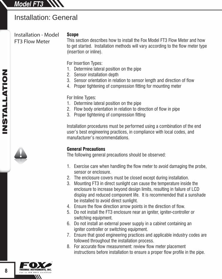
ScopeThis section describes how to install the Fox Model FT3 Flow Meter and how to get started. Installation methods will vary according to the flow meter type (insertion or inline).
For Insertion Types:1. Determine lateral position on the pipe 2. Sensor installation depth 3. Sensor orientation in relation to sensor length and direction of flow4. Proper tightening of compression fitting for mounting meter
For Inline Types:1. Determine lateral position on the pipe2. Flow body orientation in relation to direction of flow in pipe3. Proper tightening of compression fitting
Installation procedures must be performed using a combination of the end user’s best engineering practices, in compliance with local codes, and manufacturer’s recommendations.
General PrecautionsThe following general precautions should be observed: 1. Exercise care when handling the flow meter to avoid damaging the probe,
sensor or enclosure.2. The enclosure covers must be closed except during installation.3. Mounting FT3 in direct sunlight can cause the temperature inside the
enclosure to increase beyond design limits, resulting in failure of LCD display and reduced component life. It is recommended that a sunshade be installed to avoid direct sunlight.
4. Ensure the flow direction arrow points in the direction of flow.5. Do not install the FT3 enclosure near an igniter, igniter-controller or
switching equipment.6. Do not install an external power supply in a cabinet containing an
igniter controller or switching equipment.7. Ensure that good engineering practices and applicable industry codes are
followed throughout the installation process.8. For accurate flow measurement: review flow meter placement
instructions before installation to ensure a proper flow profile in the pipe.
Installation - Model FT3 Flow Meter
8
Model FT3IN
STALLATIO
N
Installation: General
Insertion Flow Meter Lateral Placement
FLOW
10X Pipe ID
ProperPro�le
15X Pipe ID
IrregularPro�le
F1 F2 F3 F4
F1 F2 F3 F4
i
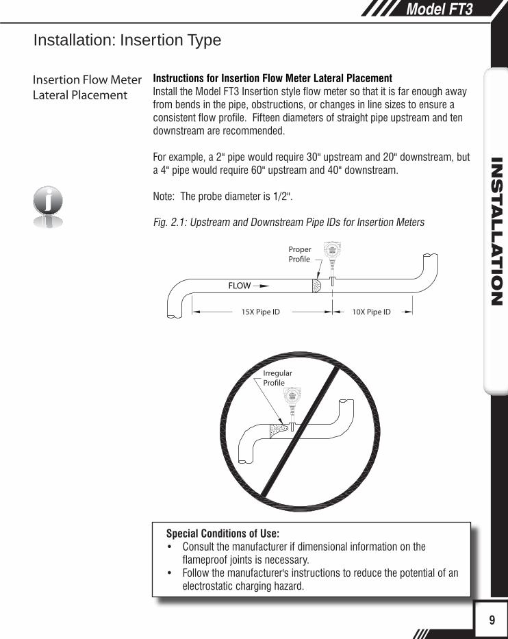
Instructions for Insertion Flow Meter Lateral PlacementInstall the Model FT3 Insertion style flow meter so that it is far enough away from bends in the pipe, obstructions, or changes in line sizes to ensure a consistent flow profile. Fifteen diameters of straight pipe upstream and ten downstream are recommended.
For example, a 2" pipe would require 30" upstream and 20" downstream, but a 4" pipe would require 60" upstream and 40" downstream.
Note: The probe diameter is 1/2".
Fig. 2.1: Upstream and Downstream Pipe IDs for Insertion Meters
Special Conditions of Use:• Consult the manufacturer if dimensional information on the
flameproof joints is necessary.• Follow the manufacturer's instructions to reduce the potential of an
electrostatic charging hazard.
9
Installation: Insertion Type
Model FT3IN
STALLATIO
N
Insertion Flow Meter Lateral Placement
Half Coupling,3/4" NPT Female(Supplied byCustomer)
Compression Fitting(Supplied by Fox)
Customer’s Pipe
.87" (22.098 mm)LC
Probe Diameter, 1/2”
F1 F2 F3 F4
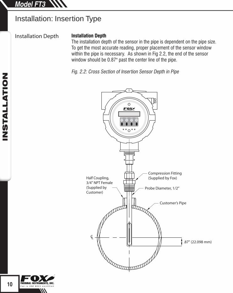
Installation DepthThe installation depth of the sensor in the pipe is dependent on the pipe size. To get the most accurate reading, proper placement of the sensor window within the pipe is necessary. As shown in Fig 2.2, the end of the sensor window should be 0.87" past the center line of the pipe.
Fig. 2.2: Cross Section of Insertion Sensor Depth in Pipe
10
Installation: Insertion Type
Model FT3IN
STALLATIO
N
Installation Depth Sensor Orientation - Direction of Flow

F1 F2 F3 F4
FLOW
Pipe
Flow Direction Arrow
+10°
-10°
FLOW
FLOW
i
Fig. 2.3: Orientation of Insertion Type Flow Meter
Note: Some flow meters are shipped with the sensor elements that are offset (see figure 2.4). Others are shipped with sensors that have equal length elements (see figure 2.5). The sensor type supplied was selected at the factory to be the best suited for your application. Follow the appropriate sensor orientation instructions.
Unequal Length Sensor ElementsInstall the shorter sensor element upstream from the longer one.
Fig. 2.4: Unequal Length Sensor Elements
11
Installation: Insertion Type
Model FT3IN
STALLATIO
N
Sensor Orientation - Direction of Flow
Sensor Orientation - Unequal Length Sensors

+10°
-10°
FLOW
FLOW
i
Equal Length Sensor ElementsInstall flow meter with both sensor elements facing the flow stream within ±10˚. Fig. 2.5: Equal Length Sensor Elements
Insertion Mounting Instructions - Compression FittingsThe Model FT3 is mounted through a ¾" hole and a ¾" female NPT half coupling provided in the customer's pipe. Insertion style flow meters are not designed for use in pipes smaller than 1½".• Install the compression fitting into the ¾-inch female NPT half
coupling.• When installing in a 2" pipe or larger, install the end of the probe 0.87"
past the center line of the pipe and tighten the compression fitting nut (refer to figure 2.2 on p. 10).
• When installing into a 1½" pipe carefully install the probe into the pipe until it touches the opposite wall and pull back 0.1". Tighten the compression fitting nut.
Caution: Once the compression fitting is locked onto the probe, the probe can be removed or rotated, but the insertion depth is locked in place.
Note: Do not overtighten compression fitting.
Fig. 2.6: Proper Tightening of the Compression Fitting Nut
While holding the fitting body steady, tighten the nut one and one-quarter turn to the 9 o'clock position.
Installation: Inline Type
Flow Meter Placement -Inline Type
12
Model FT-3IN
STALLATIO
N
12
Installation: Insertion Type
Model FT3IN
STALLATIO
N
Mounting -Insertion Type
Sensor Orientation - Equal Length Sensors

FLOW
4X Pipe ID
ProperPro�le
8X Pipe ID
IrregularPro�le
F1 F2 F3 F4
F1 F2 F3 F4
Instructions for Inline Flow Meter PlacementInstall the Model FT3 Inline style flow meter so that it is far enough away from bends in the pipe, obstructions, or changes in line sizes to ensure a consistent flow profile. Eight diameters of straight pipe upstream and four downstream are recommended (for ¼" meters: 6” (152 mm) of straight, unobstructed pipe upstream and downstream are required).
For example, a 2" pipe would require 16" upstream from the edge of the flow body and 8" downstream from the other end of the flow body, whereas a 4" pipe would require 32" upstream and 16" downstream.
The Model FT3 is welded, threaded or flanged to the customer’s pipe. Care should be taken to ensure that the diameter of the mating pipe is the same diameter as the Model FT3 flow body or errors in flow readings can occur. The installation procedure should be a combination of the end user’s best engineering practices, in compliance with local codes, and the manufacturer’s recommendations.
See Figure 2.7 for a detailed look at upstream and downstream pipe diameters for inline meters.
Fig. 2.7: Upstream and Downstream Pipe IDs for Inline Meters
13
Installation: Inline Type
Flow Meter Placement -Inline Type
Model FT3IN
STALLATIO
N

FLOW
Flow Body
F1 F2 F3 F4
Inline OrientationInstall the flow body so that the engraved arrow on the fitting and the arrow on the flow body are pointing with the direction of flow.
Fig. 2.8: Orientation of an Inline Meter - Directional Arrows
Tightening Compression FittingsThe compression fitting has been placed according to the proper depth in the flow body by Fox factory technicians. After the flow body has been correctly fitted to the process pipe, the compression fitting may need to be tightened correctly (see figure 2.6 on p. 12).
Note:• Refer to the Fox FT3 Calibration Validation User's Guide for
information on setting the field baseline for Zero CAL-CHECK™ tests if you plan to perform these tests in the pipe.
• Please save the PVC sensor cover that was shipped with your meter. It will be needed to perform Zero CAL-CHECK™ tests out of pipe.
Wiring: General
Scope
Precautions
Power Wiring
14
Installation: Inline Type
Mounting - Inline Type
Flow Body Orientation -Inline Type
Model FT3IN
STALLATIO
N
Signal Wiring

Wiring InstructionsWire the FT3 by opening the rear enclosure cover, bringing customer supplied wires in through the conduit openings and connecting to the terminal blocks. The FT3 has two conduit openings to maintain separation between AC input power and output signal wiring. To eliminate the possibility of noise interference, use a separate conduit for AC power and cut all wires short for a minimum service loop.
Wiring Precautions• WARNING - DO NOT OPEN THE ENCLOSURE WHEN ENERGIZED OR AN
EXPLOSIVE ATMOSPHERE IS PRESENT.• All plumbing and electrical installations of flow meters must be in compliance
with local codes, the end user’s best engineering practices, and manufacturer’s recommendations.
• An external power disconnect and 16A over-current protection are required for the AC and DC powered FT3.
• Do not install the FT3 enclosure near an igniter, igniter-controller or switching equipment.
• Do not install an external power supply in a cabinet containing an igniter controller or switching equipment.
• This flow meter contains components that can be damaged by static electricity. You must discharge yourself by touching a grounded steel pipe or other grounded steel material prior to working inside this flow meter.
• For the remote sensor option, the serial number of the electronics enclosure must match the remote sensor probe.
• Close any unused entries using suitably certified plugs Power Wiring For power wiring, use stranded copper wire, no larger than 16-gauge. If an external 24VDC power source is used, twisted pair shielded cable is recommended. Supply connection wiring must be rated for at least 90°C.
GroundingThe enclosure must be properly grounded with a quality earth ground. 16 gauge, stranded wire is recommended.
Signal WiringFor signal wiring, the recommended wire gauge is 18 to 22 AWG. Always use twisted pair shielded cable. The cable shield should not be connected at the flow meter, it should be connected at the power supply AC ground terminal or instrumentation AC ground. Do not route the power and signal wires in the same conduit. Power wires must enter left-hand conduit entry. Signal and remote sensor (where applicable) must enter right-hand conduit entry.
15
Wiring: General
Scope
Precautions
Power Wiring
Model FT3W
IRIN
G
Grounding
Signal Wiring

2x 3/4 inch NPT Female F1 F2 F3 F4
Signal Wiring,Serial Communication,Remote Sensor Wiring
InputPower
i
i
Serial Communication WiringIf you have purchased communications options, please refer to one of the following appropriate Fox Instruction Manuals:
• Fox FT3 RS485 Modbus Manual• Fox FT3 HART Manual
Remote Sensor WiringNote: Remote wiring is only required when the Remote Electronics options is provided. Five wire shielded cable required, the recommended wire gauge is 18 AWG. Make sure that the cable length does not exceed 100 feet and the wire resistance does not exceed one ohm. Do not connect the cable shield at the electronics enclosure end.
Fig. 3.1: FT3 Wiring
Note:Serial numbers: If you have more than one meter, you must ensure that the serial numbers of the probe/J-Box, remote electronics, housing, and/or flow body match one another. These items have been manufactured and calibrated to operate as a unit and cannot be mismatched.
Installation wiring: Obtain the correct length for the FT3 power and signal wires using one of these methods:• Trim the wires to extend 2.5 inches out of the enclosure after the
conduit and wires are routed to the FT3 (preferred method).• Trim the wires to extend 6 inches from the end of the conduit before
it is attached to the FT3.
16
Wiring: General
Model FT3W
IRIN
G
Serial Communication Wiring
Power Input Wiring
Remote Sensor Wiring
FT3 Wiring
4-20FLOW
TS424VOUT
4-20#2
Red 1
Red2
Yel 3
Wh 4
Wh 5
PULSE/ALM
TS2
TS1
F1
J2
1
24V, 0.75A
2 3
IN
+1
-2 +1
-2
+3
-4+5
-6+7
-8
TS3REMOTESENSOR
Earth Ground
24V Return
+24VDC
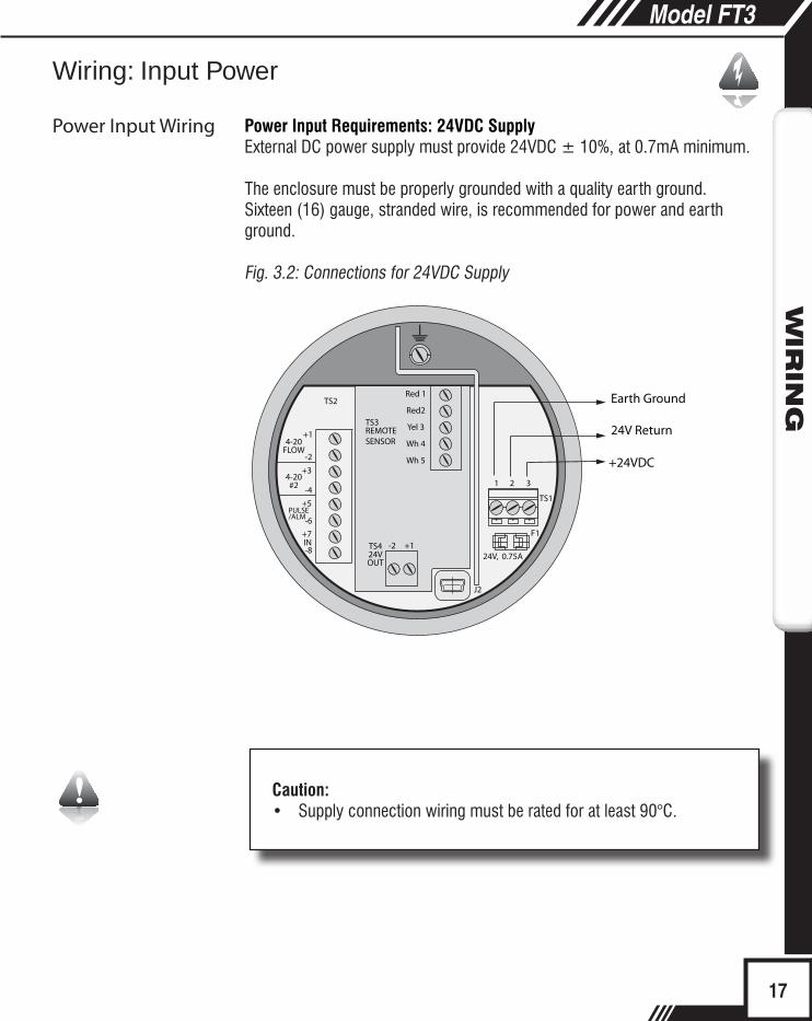
Caution:• Supply connection wiring must be rated for at least 90°C.
Power Input Requirements: 24VDC SupplyExternal DC power supply must provide 24VDC ± 10%, at 0.7mA minimum.
The enclosure must be properly grounded with a quality earth ground. Sixteen (16) gauge, stranded wire, is recommended for power and earth ground.
Fig. 3.2: Connections for 24VDC Supply
17
Model FT3W
IRIN
G
Wiring: Input Power
Power Input Wiring

4-20FLOW
TS424VOUT
4-20#2
Red 1
Red2
Yel 3
Wh 4
Wh 5
PULSE
TS2
TS1
F1
J2
1
24V, 0.75A
2 3
IN
+1
-2 +1
-2
+3
-4+5
-6+7
-8
TS3REMOTESENSOR
Earth Ground
AC (L)
AC (N)
Power Input Requirements: 100 to 240VAC SupplyIf the FT3 has the AC power supply option, the AC power must provide 100 to 240VAC -15% / +10% (85 to 264VAC) at 0.2 Amps minimum.
The enclosure must be properly grounded with a quality earth ground. Sixteen (16) gauge, stranded wire, is recommended.
Fig. 3.3: Connections for optional AC Power
Caution:• Supply connection wiring must be rated for at least 90°C.
Wiring: Input Power
18
Model FT3W
IRIN
G
Power Input Wiring 4 to 20mA Loop Power Provided by Customer(Recommended)

4-20FLOW
TS424VOUT
4-20#2
Red 1
Red2
Yel 3
Wh 4
Wh 5
PULSE/ALM
TS2
TS1
F1
J2
1
24V, 0.75A
2 3
IN
+1
+1 -2
-2
+3
-4
+5
-6+7
-8
TS3REMOTESENSOR
+24VDC
+24VDC
4 to 20mA FLOW RATE
4 to 20mA TEMPERATURE OR FLOW RATE
24VDC Return
Customer PLC or DCSFT3
24VDC Return
* (see important note below)
* (see important note below)
i
4 to 20mA Output Wiring: Customer-Supplied Power SourceBring the 4 to 20mA wiring in through the right-hand conduit hub. Connect FLOW RATE 4 to 20mA wiring to TS2, 1(+) & 2(-). Connect 4 to 20mA output #2 wiring to TS2, 3(+) & 4(-).
Fig. 3.4: 4 to 20mA Output Wiring for Customer-Supplied Power Source
Important NoteThe load resistor on the Fox Flow Meter 4 to 20mA signal is typically 250 ohms and is located in or at the customers PLC or DCS. A 250 ohm resistor in the 4 to 20mA line will result in a 1 to 5VDC signal to the PLC or DCS. Some PLC/DCS equipment has the load resistor built in to the unit; please refer to the PLC/DCS technical manual. Do not exceed a 600 ohm load on the Fox Flow Meter 4 to 20mA signal.
19
Model FT3W
IRIN
G
Wiring: Signal Wiring
4 to 20mA Loop Power Provided by Customer(Recommended)

4-20FLOW
TS424VOUT
4-20#2
Red 1
Red2
Yel 3
Wh 4
Wh 5
PULSE/ALM
TS2
TS1
F1
J1
1
24V, 0.75A
2 3
IN
+1
+1 -2
-2
+3
-4+5
-6+7
-8
TS3REMOTESENSOR 4 to 20mA FLOW RATE
4 to 20mA TEMPERATURE OR FLOW RATE
Customer PLC or DCSFT3
+
(+)1( )2
+
-
-
TS424VOUT
- * (see important note below)
* (see important note below)
i
i
4 to 20mA Output Wiring: Loop Power Provided by FT3Bring the 4 to 20mA wiring in through the right-hand conduit hub. Connect the 4 to 20mA wiring to terminal blocks TS2 and TS4 as shown in the diagram below.
Fig. 3.5: 4 to 20mA Output Wiring for Loop Power Provided by FT3
Note: This wiring option is only available with the isolated 24V ouput power option.
Important NoteThe load resistor on the Fox Flow Meter 4 to 20mA signal is typically 250 ohms and is located in or at the customers PLC or DCS. A 250 ohm resistor in the 4 to 20mA line will result in a 1 to 5VDC signal to the PLC or DCS. Some PLC/DCS equipment has the load resistor built in to the unit; please refer to the PLC/DCS technical manual. Do not exceed a 600 ohm load on the Fox Flow Meter 4 to 20mA signal.
Caution:
Do not exceed 42mA total load (ie including 4-20mA outputs).
Model FT3W
IRIN
G
20
Wiring: Signal Wiring
4 to 20mA Loop Power Provided by FT3
WIR
ING
Frequency/Alarm Output Wiring
4-20FLOW
TS424VOUT
4-20#2
Red 1
Red2
Yel 3
Wh 4
Wh 5
PULSE/ALM
TS2
TS1
F1
J1
1
24V, 0.75A
2 3
IN
+1
+1 -2
-2
+3
-4+5
-6+7
-8
TS3REMOTESENSOR
2.4K to 10K OHM
Frequency or Alarm Output
Customer PLC or DCSFT3
+
(-)2 (+)1
TS424VOUT
4-20FLOW
TS424VOUT
4-20#2
Red 1
Red2
Yel 3
Wh 4
Wh 5
PULSE/ALM
TS2
TS1
F1
J1
1
24V, 0.75A
2 3
IN
+1
+1 -2
-2
+3
-4+5
-6+7
-8
TS3REMOTESENSOR +24VDC
24VDC Return
2.4K to 10K OHM
Frequency or Alarm Output
Customer PLC or DCSFT3
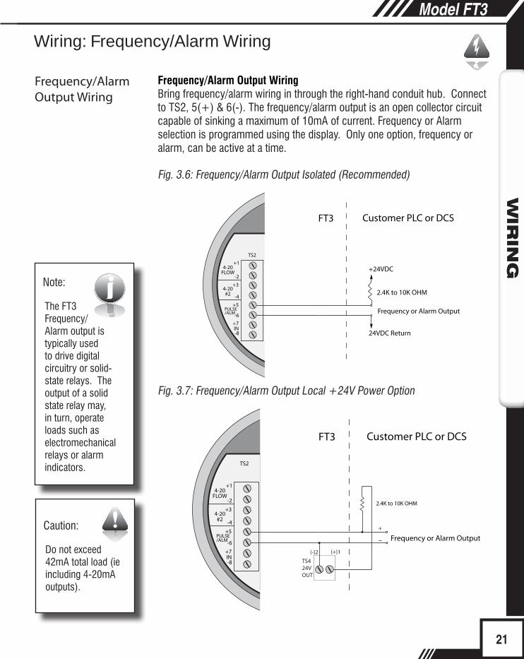
Frequency/Alarm Output WiringBring frequency/alarm wiring in through the right-hand conduit hub. Connect to TS2, 5(+) & 6(-). The frequency/alarm output is an open collector circuit capable of sinking a maximum of 10mA of current. Frequency or Alarm selection is programmed using the display. Only one option, frequency or alarm, can be active at a time.
Fig. 3.6: Frequency/Alarm Output Isolated (Recommended)
Fig. 3.7: Frequency/Alarm Output Local +24V Power Option
Note:
The FT3 Frequency/Alarm output is typically used to drive digital circuitry or solid-state relays. The output of a solid state relay may, in turn, operate loads such as electromechanical relays or alarm indicators.
Caution:
Do not exceed 42mA total load (ie including 4-20mA outputs).
i
21
Model FT3W
IRIN
G
Wiring: Frequency/Alarm Wiring
Frequency/Alarm Output Wiring
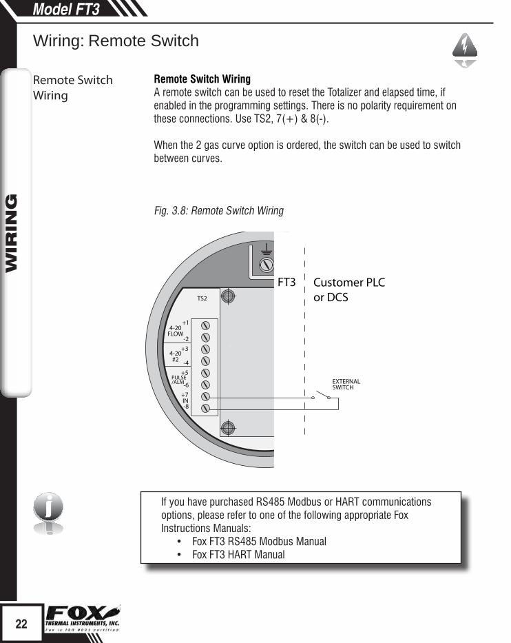
Remote Switch WiringA remote switch can be used to reset the Totalizer and elapsed time, if enabled in the programming settings. There is no polarity requirement on these connections. Use TS2, 7(+) & 8(-).
When the 2 gas curve option is ordered, the switch can be used to switch between curves.
Fig. 3.8: Remote Switch Wiring
If you have purchased RS485 Modbus or HART communications options, please refer to one of the following appropriate Fox Instructions Manuals:
• Fox FT3 RS485 Modbus Manual• Fox FT3 HART Manual
i
22
Model FT3W
IRIN
G
4-20FLOW
4-20#2
PULSE/ALM
TS2
TS1
F1
J1
1
24V, 0.75A
2 3
IN
+1
-2
+3
-4+5
-6+7
-8
EXTERNAL SWITCH
FT3 Customer PLC or DCS
Wiring: Remote Switch
Remote Switch Wiring
WIR
ING
2X 3/4 " NPT,Female
Remote Cable, 5 Conductor,Shielded, 100ft (30.48m) Max.
F1 F2 F3 F4
InputPower
Signal Wiring
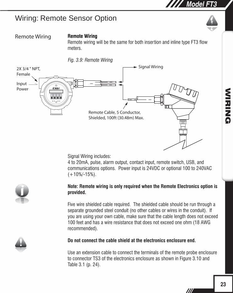
Remote WiringRemote wiring will be the same for both insertion and inline type FT3 flow meters.
Fig. 3.9: Remote Wiring
Signal Wiring includes:4 to 20mA, pulse, alarm output, contact input, remote switch, USB, and communications options. Power input is 24VDC or optional 100 to 240VAC (+10%/-15%).
Note: Remote wiring is only required when the Remote Electronics option is provided.
Five wire shielded cable required. The shielded cable should be run through a separate grounded steel conduit (no other cables or wires in the conduit). If you are using your own cable, make sure that the cable length does not exceed 100 feet and has a wire resistance that does not exceed one ohm (18 AWG recommended).
Do not connect the cable shield at the electronics enclosure end.
Use an extension cable to connect the terminals of the remote probe enclosure to connector TS3 of the electronics enclosure as shown in Figure 3.10 and Table 3.1 (p. 24).
23
Model FT3W
IRIN
G
Wiring: Remote Sensor Option
Remote Wiring
i

TS424VOUT
TS 5
TS1
F1
J2
1
24V,0.75A
2 3
-2 +1
TS3
#4
#6
#3
#5
#2
#1
Black Dot Denotes Pin #1
Cable Shield
Electronics Enclosure
RED
RED
WHTWHT
GRNWHT
Shield
GRN
BRN
YEL
BLK
RED
Probe Sensor Wired By FoxSENSOR
RED*
BLK*
BRN*
WHT*
GRN*
1
2
3
4
5
RED
RED
YEL
WHT
WHT
Remote Enclosure
Sensor Wires
Fig. 3.10: Remote Sensor Wiring
*Wire colors listed here represent the wire colors of cables supplied by Fox. Colors may vary if customer is supplying their own cable.
Table 3.1: Remote Sensor Cable Wiring
24
Wiring: Remote Sensor
Model FT3W
IRIN
G
Electronics EnclosureTerminal Numbers
Extension CableWire Color
Remote EnclosureTerminal Numbers
Sensor WireColor
1 Red 1 Red
2 Black 2 Red
3 Brown 3 Yellow
No Connection Shield 4 Green
4 White 5 White
5 Green 6 White
Remote Sensor Cable Wiring
Input WiringRemote Sensor
Start UpSequence
Optional Display
USB Interface

Start Up SequenceThe program automatically enters the Run/Measure mode after power up. If the Local display is installed, the screen will show the software versions for the FT3 and the display module during power up. Programming of the flow meter can also be accomplished using a Windows-based PC program called FT3View™.
USB InterfaceThe USB interface is a standard feature which allows communication to a PC in order to monitor readings and configure settings. FT3View™, is a free application program from Fox that connects to the USB interface and allows data monitoring, configuration setting, data logging to Excel, and an option to save and recall FT3 configuration data. A serial communication manual is available for users who want to create their own PC application.
FT3 Optional Display Panel & Configuration PanelThe FT3 display is a 2 line x 16 character display with 4 mechanical and 4 IR (infrared) buttons. The IR and mechanical buttons perform the same function but the IR buttons can be used without opening the cover. The IR buttons can be calibrated (p. 54) for better operation in the field or disabled (p. 54) when the meter is used in snow or ice in order to avoid false key detection.
Fig. 4.1: FT3 Optional Display and Configuration Panel
F1 F2 F3 F4
IR (infrared) Buttons
Display Window
Push Buttons
25
Model FT3O
PER
ATIO
N
Operation: Start Up
Start UpSequence
Optional Display
USB Interface
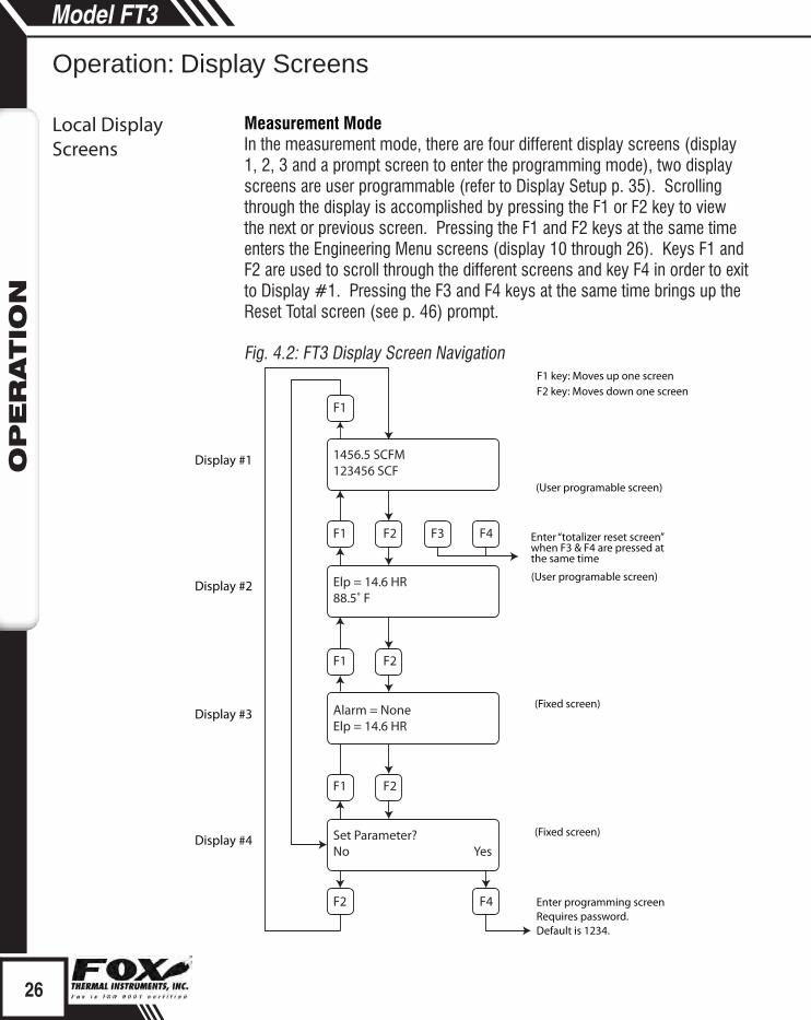
Measurement ModeIn the measurement mode, there are four different display screens (display 1, 2, 3 and a prompt screen to enter the programming mode), two display screens are user programmable (refer to Display Setup p. 35). Scrolling through the display is accomplished by pressing the F1 or F2 key to view the next or previous screen. Pressing the F1 and F2 keys at the same time enters the Engineering Menu screens (display 10 through 26). Keys F1 and F2 are used to scroll through the different screens and key F4 in order to exit to Display #1. Pressing the F3 and F4 keys at the same time brings up the Reset Total screen (see p. 46) prompt.
Fig. 4.2: FT3 Display Screen Navigation
Operation: Display Screens
Local Display Screens
26
Model FT3O
PER
ATIO
N
F1 key: Moves up one screenF2 key: Moves down one screen
(User programable screen)
(User programable screen)
Enter “totalizer reset screen” when F3 & F4 are pressed at the same time
(Fixed screen)
Enter programming screenRequires password.Default is 1234.
Display #1
Display #2
Display #3
Display #4(Fixed screen)
F1
F1
F1
F1 F2
F2 F4
F2
F2 F3 F4
1456.5 SCFM123456 SCF
Elp = 14.6 HR88.5˚ F
Alarm = NoneElp = 14.6 HR
Set Parameter?No Yes
EngineeringDisplay

3124.6 SCFMcsv=0.3432 Volt
Enter: Press F1 & F2 at the same timePress F4 to return to normal mode
Display 10
CsvAv=366809Vel=112345.7 FT/M Display 11
FloFlt=3666805.3Vel=2356.45 M/H Display 12
TsiAvr=512.5 cntTsvAvr=323.7 cnt Display 13
Tsi= 2.1345 VoltTsv=0.9856 Volt Display 14
Tsi = 0.0435 AmpTsi = 221.5 Ohm Display 15
RTD9= 345.5 cntGas Temp=123.7 °C Display 16
CH1_420=2167 cntCH2_420=1234 cnt Display 17
Feq=1234.5 cntAlarm=33,35 Display 18
FloHi= 1234 SCFMFloLo=0 SCFM Display 19
TmpHi=300 °CTmpLo=10 °C Display 20
Elp=12.5 HRStat(hex)=2800 Display 21
FT3 V3.02dDisplay V2.03b Display 22
Pwr_Cycl=24Err_tot=0 Display 23
Tsi=221.5 OhmRTD9=10.3 Ohm Display 24
CAL-V=23.51CAL-V Chk=0.2% Display 25
F2 KeyF1 Key
BrShtDnCnt=0 cnt Display 26
F3 & F4 pressed at the same time will initiate a "Total" reset
Flow in selected unitsSensor voltage in volts
Sensor average voltsVelocity in selected units
Sensor filtered average in voltsVelocity in meters/hour
TSI average countTSV average count
TSI in voltsTSV in volts
TSI current in ampsTSI resistance in ohms
RTD9 countGas Temperature in degrees C
CH1 4-20ma current loop countCH2 4-20 ma current loop count
Frequency output countAlarm codes
High flow limit alarmLow flow limit alarm
High temperature limit alarmLow temperature limit alarm
Elapsed time in hoursStatus in hexadecimal
FT3 main board firmware revisionFT3 display board firmware revision
Power cycle countError with totalizer count
TSI resistance in ohmsRTD9 resistance in ohms
CAL-V ValueCAL-V last verify value
Bridge shutdown detection count
ZRO_Pref=xx.xxxxZRO_diff=x.xx%
ZRO_Bref=xx.xxxxZRO_diff=x.xx%
Display 27
Display 28
Zero CAL-CHECK Pipe RefZero CAL-CHECK % difference
Zero CAL-CHECK Bottle RefZero CAL-CHECK % difference
FT3 Engineering DisplaysPressing the F1 & F2 keys at the same time in the normal mode, brings up the engineering displays. These displays show internal parameters of the FT3 which are used by Fox service technicians.
Press F4 to exit. Use the F1 & F2 keys to navigate.
Fig. 4.3: FT3 Engineering Displays
27
Model FT3O
PER
ATIO
N
Operation: Engineering Displays
EngineeringDisplay

i
Data Entry using the local display moduleThere are 2 basic types of menu entries: one for changing value or string and one for selecting from a selection list.
To Change a Value or String :
F1 F2 F3 F4
Press CHG (F1) key to change the value, OK (F4) to accept the value.
F1 F2 F3 F4
Press the UP (F1) or DN (F2) key to select a new digit or character, the cursor points to the selected digit. Press NXT (F3) to select the next digit and OK (F4) to accept the entry.
Note: If the UP (F1) or DN (F2) key is held down for more than 1 second, the program will progressively select new digits at increasing speed as time increases.
To Select from a List:
F1 F2 F3 F4
Press NXT (F1) key repeatedly until the correct selection is made and OK (F4) key to accept the entry.
Entering the Programming Mode
To enter the programming mode, press the F1 or F2 key repeatedly in the normal running mode until the following screen is shown:
28
Model FT3O
PER
ATIO
NModel FT3
Operation: Programming
Programming Usingthe Local Display
Value or String
Selecting from a List
Enter Programming Mode
VALUE = 0.91234CHG OK
VALUE = 0.91234UP DN NXT OK
FLO UNT = SCFMNXT OK
Programming Usingthe Local Display

F1 F2 F3 F4
Press YES (F4) and the following screen will prompt the user to enter the password if it is active:
F1 F2 F3 F4
Enter the correct password, then follow the instructions for changing a value as specified above. The default Level 1 password is “1234”.
If the wrong password is entered, the message “Wrong Password” will be displayed for a few seconds and then returns to the programming entry screen. If the password is accepted, the base programming screen will be shown:
F1 F2 F3 F4
This is the base screen for the programming mode.
Press EXIT (F4) repeatedly until “Normal Mode” is seen briefly to exit the programming mode.
Analog 4 to 20mA OutputThe following menu allows the scaling of the analog 4 to 20mA outputs.
From the base screen, press I/O (F1) and then in the next screen press 420 (F3).
F1 F2 F3 F4
29
Model FT3O
PER
ATIO
N
Operation: Programming
Programming Usingthe Local Display
Analog 4 to 20mA Output
SET PARAMETERS ?No Yes
PASWD:_UP DN NXT OK
SET PARAMETERSI/O FLO DSP EXIT
SET I/OCOM I/O 420 EXIT

i
i
F1 F2 F3 F4
Select CH1 (F1) to program channel 1.
F1 F2 F3 F4
Enter the value for the 20mA and press OK (F4) key to accept the setting.
Then the following screen will display:
F1 F2 F3 F4
Enter the value for the 4mA and press OK (F4).
Note: 4mA is normally set to 0.
F1 F2 F3 F4
This menu allows the user to select an alarm level on the 4 to 20mA when a serious issue is detected that is preventing the calculation of a correct flow value.
The options are:Force the 4 to 20mA signal to 3.6mAForce the 4 to 20mA signal to 21mADo not force 4 to 20mA signal (not used)
Press (F4) repeatedly until “Normal Mode” is seen briefly to exit the programming mode.
Note: When the flow rate exceeds the programmed value for the 20mA
30
Model FT3O
PER
ATIO
N
Operation: Programming
Programming Usingthe Local Display
SET 4-20 mACH1 CH2 EXIT
20 mA = 3751 SCFMCHG OK
4 mA = 0 SCFMCHG OK
mA Fault = 3.6 mANXT OK

i
set point, the analog output will stay at 20mA and an alarm code will be generated.Select CH2 (F2) to program channel 2.Channel 2 is programmable for flow (CH2=Flow)or temperature (CH2=Temp).
F1 F2 F3 F4
Press NXT (F1) to select Flow or Temperature and then press OK (F4).
F1 F2 F3 F4
Enter the value for the 20mA and press OK (F4) key to accept setting.
Then the following screen will show:
F1 F2 F3 F4
Enter the value for the 4mA and press OK (F4). Press EXIT (F4) repeatedly until “Normal Mode” is seen briefly to exit the programming mode.
Note: When the flow rate exceeds the programmed value for the 20mA set point, the analog output will stay at 20mA and an alarm code will be generated.
Frequency OutputFrom the main menu, press I/O (F1), I/O (F2) and then OUT (F2)
F1 F2 F3 F4
31
Model FT3O
PER
ATIO
N
Operation: Programming
Programming Usingthe Local Display
Frequency Output
CH2= TempNXT OK
20 mA = 300 ° FCHG OK
4 mA = 10 ° FCHG OK
SET I/OINP OUT EXIT

i
Press OUT (F2) to select output and the following screen may show:
F1 F2 F3 F4
Press NEXT (F1) to cycle through output options until you have the selection for "OUT=Frequency" and press OK (F4).
The frequency output can be configured in one of three ways: (1) specifying a maximum frequency to a defined maximum value of flow rate, (2) specifying how many flow units total per pulse, U/P (i.e., 0.1 SCF per pulse) or (3) specifying how many pulses per unit, P/U (i.e., 10 pulses per SCF). All of these approaches are equivalent.
F1 F2 F3 F4
Use P/U (F1) to enter pulse per unit, U/P (F2) for Unit per pulse or FEQ (F3) to enter the flow and maximum frequency to scale the frequency output.
Note: When data is entered with any of the three described methods, the other values will be re-calculated according to the settings.
Entering data in Pulse per Unit:Press P/U (F1) and the following screen will show:
F1 F2 F3 F4
Press CHG (F1) to change the setting and then OK (F4) to accept entry.
The value entered is in pulse per selected flow unit total (i.e., 10 pulses per SCF)
32
Model FT3O
PER
ATIO
N
Operation: Programming
Programming Usingthe Local Display
Pulse per Unit
OUT = FrequencyNXT OK
FREQUENCY OUTPUT P/U U/P FEQ EXIT
PLS/UNT = 1.2CHG OK

i
Entering data in Unit per Pulse:Press U/P (F2) and the following screen will show:
F1 F2 F3 F4
Press CHG (F1) to change the setting and then OK (F4) to accept entry.The value entered is in unit per pulse (i.e. 0.01 flow unit total per pulse)
Entering data with flow and maximum frequency:Press FEQ (F3) and the following screen will show:
F1 F2 F3 F4
Enter the maximum frequency and press OK (F4)(Maximum frequency should not exceed 100 Hz)
The next screen will show:
F1 F2 F3 F4
Note: When the flow rate exceeds the maximum frequency set point, the output will stay at that maximum frequency but the FT3 will issue an alarm code.
Caution: Equation to ensure pulse rate must not exceed 100 Hz.
Alarm OutputTo program the Alarm output, press I/O (F1) key from the "SET PARAMETERS" menu screen, then select I/O (F2) and the screen will show:.
F1 F2 F3 F4
33
Model FT3O
PER
ATIO
N
Programming Usingthe Local Display
Operation: Programming
Max Flow and Frequency
Alarm Output
Unit per Pulse UNT/PLS = 0.01CHG OK
MaxFreq=98.5 HzCHG OK
MaxFlo=4999.8 SCFMCHG OK
SET I/OINP OUT EXIT

i
Then press OUT (F2) and the screen may show:
F1 F2 F3 F4
Then press NXT (F1) to select the correct alarm and press OK (F4).Selections are:
HiFloAlm = High Flow AlarmLoFloAlm = Low Flow AlarmHiTempAlm = High Temperature AlarmLoTempAlm = Low Temperature AlarmNot usedFrequency
F1 F2 F3 F4
Enter the value for the limit by pressing CHG (F1) and then OK (F4).
Note: There is only one output to operate as a frequency output or an alarm output. Both cannot operate at the same time.
For Discrete Input Settings:From the main menu, press I/O (F1) and then I/O (F2) and then INP (F1) key to select input. The following menu will display:
F1 F2 F3 F4
Press NXT (F1) repeatedly until the correct selection is shown and then press OK (F4) to accept the setting.
Selections are: Not usedTot Reset Reset the totalizerSwitch Crv Switch between calibration curve 1 and curve 2 (only if 2 gas curve ordered)
Press EXIT (F4) repeatedly until you exit programming mode.
34
Model FT3O
PER
ATIO
N
Operation: Programming
Programming Usingthe Local Display
Discrete Input
OUT = HiFloAlmNXT OK
HiFloAlm=500 SCFMCHG OK
INP = Not UsedNXT OK

Serial Communication
Display Setup
i
Serial Communication SettingsTo program the Serial communication settings, press I/O (F1) key from the base menu.
F1 F2 F3 F4
Press COM (F1) to select Serial communication:
F1 F2 F3 F4
Options for serial communication are:Not UsedHARTModbus
Note: Any selection other than "Not Used" requires the communication option for the selected communication type. If enabling a communication option, see the associated Fox Communication Manual for specific programming information: FT3 Modbus Manual or FT3 HART Manual.
Display SetupRemember, there are four display screens that you can cycle through in normal operating mode (see Figure 4.2 on p. 26). Two of the four display screens are fixed and cannot be changed (displays #3 & 4). The other two screens are programmable to show the information that you prefer and is discussed in this section.
Display #1 Display #2
F1 F2 F3 F4
F1 F2 F3 F4
35
Model FT3O
PER
ATIO
N
Operation: Programming
Programming Usingthe Local Display
SET I/OCOM I/O 420 EXIT
Comm=ModbusNXT OK
DSP1L1DSP1L2
DSP2L1DSP2L2

Programming Display Screens #1 & 2
Selections are:DSP1L1 Display 1, Line 1DSP1L2 Display 1, Line 2DSP2L1 Display 2, Line 1DSP2L2 Display 2, Line 2
To Program Display Screens #1 & 2:
From the base programming menu press DSP (F3) to select the display menu:
F1 F2 F3 F4
F1 F2 F3 F4
Press DSP (F1) key. The display will show:
F1 F2 F3 F4
These are the selections for the display #1 line #1.
Selections are: Flo rate Flow rateTotal Total massElps Elapsed timeTemp TemperatureAlarm Error codes
When the selection is correct, press OK (F4) to accept. The display will then go through the same process for all 4 lines of the 2 programmable displays (DSP1L1, DSP1L2, DSP2L1 and DSP2L2).
36
Model FT3O
PER
ATIO
N
Operation: Programming
Programming Usingthe Local Display
SET PARAMETERSI/O FLO DSP EXIT
DISPLAY/PASSWORDDSP IR PSW EXIT
DSP1L1 = TotalNXT OK

Password
After the last line of display 2 is accepted, the display will show the following menu:
F1 F2 F3 F4
This menu allows you to alternate between menu display 1 and 2 every few seconds.
Selections are: On or Off
Press OK (F4) to accept selection.
Press EXIT (F4) repeatedly until “Normal Mode” is seen briefly to exit the programming mode.
PasswordThere are two user level passwords, only Level 1 is programmable and gives access to all the normal settings. The second password is used to allow access to calibration factors and should normally never be changed unless advised by the Fox service department, or to set a new password in the event that the user forgets the Level 1 password.
Default Level 1 password is “1234”, and Level 2 password is “9111”.
The Level 1 programmable password can be disabled by setting it to “0”.
From the base programming menu press DSP (F3) to select the display menu:
F1 F2 F3 F4
F1 F2 F3 F4
37
Model FT3O
PER
ATIO
N
Operation: Programming
Programming Usingthe Local Display
ALTERNATE = OffNXT OK
SET PARAMETERSI/O FLO DSP EXIT
DISPLAY/PASSWORDDSP IR PSW EXIT

Programming Password
Units Settings
i
To Program the Password:Press PSW (F2) key to select password.
F1 F2 F3 F4
This screen displays the current Level 1 password.Press CHG (F1) key to change the password and enter new value (see p. 28
for further details).
Press OK (F4) to accept new data and exit programming by pressing EXIT (F4) key repeatedly until out of the programming mode.
Note: Password can be number or letter characters up to 4 digits.
Units SettingsThis menu is used to set the units for mass flow, temperature, pressure reference and the settings of reference temperature, reference pressure and density of gas when using Lbs/time or Kg/time.
These values will be set at Fox, using the Application Data Sheet values. If the customer changes the application, these values can be changed to match the new application. Check with Fox customer service before changing the application gas.
The unit setting is accessed from the base programming menu by pressing FLO (F2):
F1 F2 F3 F4
F1 F2 F3 F4
Press UNT (F2) for Unit selection:
38
Model FT3O
PER
ATIO
N
Operation: Programming
Programming Usingthe Local Display
PASSWD = 1234CHG OK
SET PARAMETERS I/O FLO DSP EXIT
FLOW PARAMETERS 1DGN UNT PRM EXIT

i
F1 F2 F3 F4
Press NXT (F1) to change selection and OK (F4) to accept.
Selections for Flow unit are:
SCFM LBS/S NLPS
SCFH NLPH MSCFD (MCFD)
NM3/H NLPM SM3/H
NM3/M SMPS MT/H
KG/H NMPS NM3/D
KG/M SFPM MMSCFM (MMCFM)
KG/S MMSCFD (MMCFD) SCFD
LBS/H LBS/D MCFD (MSCFD)
LBS/M SLPM SM3/M
SM3/D
Note: The totalizer (total flow measured) will roll over when reaching a certain value. The maximum value is dependent on the flow units selected.
Maximum Total Rollover Value:Most flow units: 99,999,999,999MSCFD: 999,999,999MMSCFM: 9,999,999MMSCFD: 999,999
WARNING: The FT3 re-calculates area, 4 and 20mA values, maximum flow for the frequency output and zero flow cutoff when changing flow units except for velocity units. When going to or from velocity units, the FT3 will not recalculate these values and these values must be re-entered manually.
After pressing OK (F4) to accept the Flow unit the display will prompt for the temperature unit setting:
39
Model FT3O
PER
ATIO
N
Operation: Programming
Programming Usingthe Local Display
FLO = SCFMNXT OK
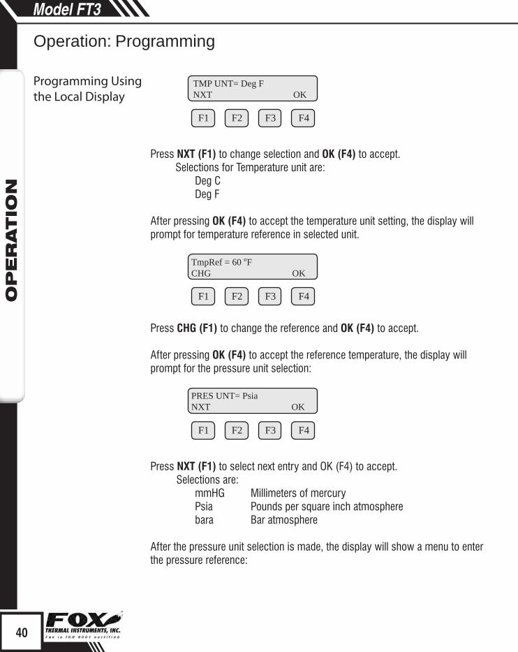
F1 F2 F3 F4
Press NXT (F1) to change selection and OK (F4) to accept.Selections for Temperature unit are:
Deg CDeg F
After pressing OK (F4) to accept the temperature unit setting, the display will prompt for temperature reference in selected unit.
F1 F2 F3 F4
Press CHG (F1) to change the reference and OK (F4) to accept.
After pressing OK (F4) to accept the reference temperature, the display will prompt for the pressure unit selection:
F1 F2 F3 F4
Press NXT (F1) to select next entry and OK (F4) to accept.Selections are:
mmHG Millimeters of mercuryPsia Pounds per square inch atmospherebara Bar atmosphere
After the pressure unit selection is made, the display will show a menu to enter the pressure reference:
TmpRef = 60 °FCHG OK
PRES UNT= PsiaNXT OK
40
Model FT3O
PER
ATIO
N
Operation: Programming
Programming Usingthe Local Display
TMP UNT= Deg FNXT OK

i
Flow Parameters
F1 F2 F3 F4
Press CHG (F1) to change it and OK (F4) to accept.After the pressure reference is accepted, the display will prompt for the gas density if LBS or KG was selected for flow unit:
F1 F2 F3 F4
Press CHG (F1) to change and OK (F4) to accept.
Note: The density entry is only used when KG/time or LBS/time is selected for flow rate units.
Density conditions are referenced to 0 C° at 760 mmHg.
Flow ParametersThis is the menu used to set various flow parameter values. They are:Flow cutoff, pipe area, filter, high and low alarm for flow and temperature.
F1 F2 F3 F4
The menu is accessed from the base programming menu by pressing FLO (F2):
F1 F2 F3 F4
Then press PRM (F3):
41
Model FT3O
PER
ATIO
N
Operation: Programming
Programming Usingthe Local Display
PresRef= 14.7CHG OK
DNS = 0.988876 KG/m3CHG OK
SET PARAMETERS I/O FLO DSP EXIT
FLOW PARAMETER 1DGN UNT PRM EXIT

iF1 F2 F3 F4
Note: The CAL and SPC function key will only appear and be accessible from a Level 2 password.
Then press PRM (F3) for Flow Cutoff:
F1 F2 F3 F4
When the flow rate falls below the zero flow cutoff, the flow meter will display a flow value of zero. Enter the value for the percent low flow cutoff and then press OK (F4).
F1 F2 F3 F4
Enter the pipe area in square meters or square feet and then press OK (F4).
Use square meter for metric flow unit selection and square feet for English flow unit selection.
F1 F2 F3 F4
The filter value is also referred to as a dampening factor and is used to quiet the readings. The filter value is an exponential filter that dampens the noise and is used as follows:
42
Model FT3O
PER
ATIO
N
Operation: Programming
Programming Usingthe Local Display
Filter Value
Pipe Area
Flow Cutoff
FLOW PARAMETER 2CAL SPC PRM EXIT
CUTOFF = 2.0 SCFMCHG OK
A^2 = 0.05672 Ft^2CHG OK
FILTER = 0.8CHG OK

Flow Value = (FA * new value) + (FB * average) Where FA = filter value, FA + FB is equal to 1.0.
A lower filter value will increase dampening of the flow rate and smooth the reading. A lower filter value will also slow the meter’s response. For example, if we enter a filter of 0.8, the weight ratio for new average is:
New average = (80% new sample) + (20% last average) Filter range is 0.01 to 1.0, 0.01 being a high filter value and 1.0 = no filter.
Enter the filter value and then press OK (F4).
F1 F2 F3 F4
This is the upper flow limit alarm value that can be associated with a discrete output. An alarm code is generated when the flow value exceeds this limit. If no checking is needed, this value should be set to zero.
Press OK (F4) to accept the value.
HiFloAlm = 1234 SCFMCHG OK
43
Model FT3O
PER
ATIO
N
Operation: Programming
Programming Usingthe Local Display
High Flow Rate Alarm
Filter Response (Sec.) 65% of Target0.09 0.10
0.8 0.15
0.7 0.20
0.6 0.25
0.5 0.30
0.4 0.35
0.3 0.40
0.2 0.60
0.1 1.00
0.05 2.00
0.03 3.00
0.01 10.3
i
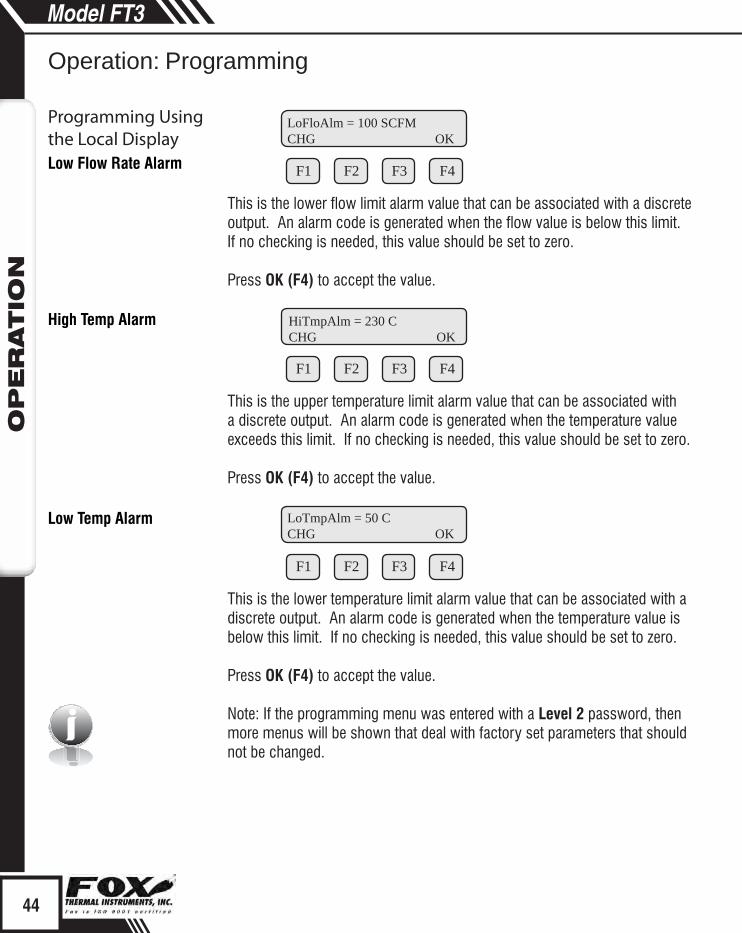
F1 F2 F3 F4
This is the lower flow limit alarm value that can be associated with a discrete output. An alarm code is generated when the flow value is below this limit. If no checking is needed, this value should be set to zero.
Press OK (F4) to accept the value.
F1 F2 F3 F4
This is the upper temperature limit alarm value that can be associated with a discrete output. An alarm code is generated when the temperature value exceeds this limit. If no checking is needed, this value should be set to zero. Press OK (F4) to accept the value.
F1 F2 F3 F4
This is the lower temperature limit alarm value that can be associated with a discrete output. An alarm code is generated when the temperature value is below this limit. If no checking is needed, this value should be set to zero.
Press OK (F4) to accept the value.
Note: If the programming menu was entered with a Level 2 password, then more menus will be shown that deal with factory set parameters that should not be changed.
44
Model FT3O
PER
ATIO
N
Operation: Programming
Programming Usingthe Local DisplayLow Flow Rate Alarm
High Temp Alarm
Low Temp Alarm
LoFloAlm = 100 SCFMCHG OK
HiTmpAlm = 230 CCHG OK
LoTmpAlm = 50 CCHG OK

Calibration Parameters
Calibration ParametersThis menu allows changing the factory calibrated setting of the flow meter and is accessible with a Level 2 password. Calibration parameter values are set for temperature and pressure at 0 degree C and 760 mmHg.
These settings should normally never be changed except by Fox Thermal Instrument personnel at the factory.
This menu is entered from the base menu and pressing FLO, PRM and CAL.
F1 F2 F3 F4
Press CAL (F1) then the display will show:
F1 F2 F3 F4
Press TB1 (F1) then the display will show:
F1 F2 F3 F4
Press NXT (F3) then the display will show:
F1 F2 F3 F4
Use the CHG (F1) key to change the entry, PRV (F2) to move to the previous entry, NXT (F3) to move to the next entry and EXIT (F4) to return.
Pressing the NXT (F3) key will show the data point voltage and then mass velocity and then go to the next data point. The number after Volt (i.e., Volt1) or Flo (i.e., Flo1) indicated the data point number.
45
Model FT3O
PER
ATIO
N
Operation: Programming
Programming Usingthe Local Display
FLOW PARAMETER 2CAL SPC PRM EXIT
CAL TABLETB1 - - - - - - EXIT
Volt1 = 0.92367CHG PRV NXT EXIT
Flo1 = 0CHG PRV NXT EXIT
Reset Total
iTotalizer Rollover
Restore Database
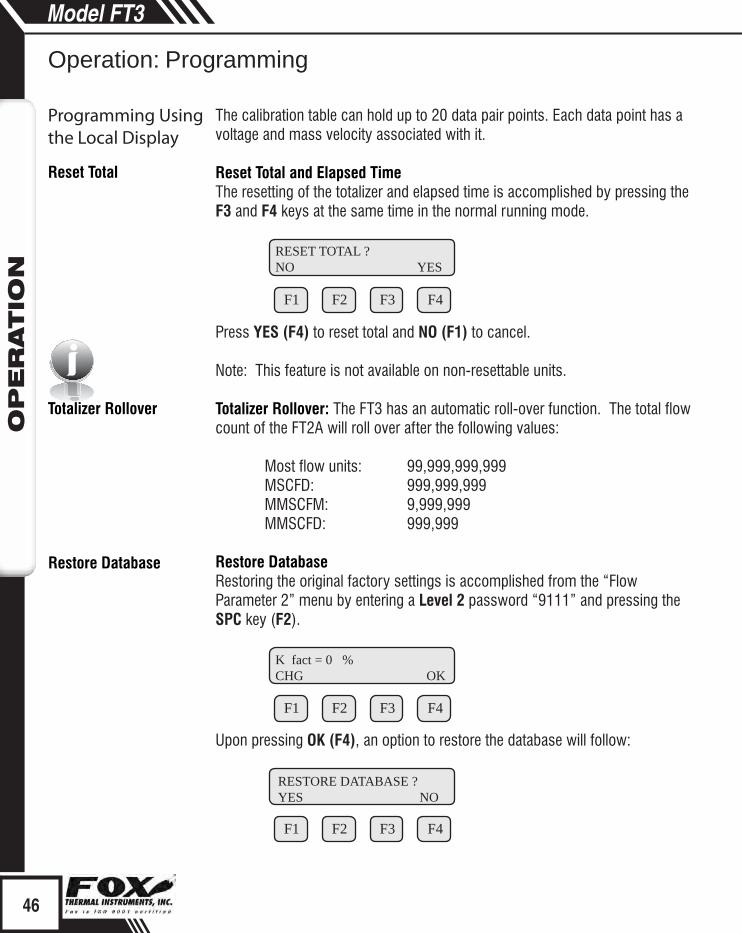
The calibration table can hold up to 20 data pair points. Each data point has a voltage and mass velocity associated with it.
Reset Total and Elapsed TimeThe resetting of the totalizer and elapsed time is accomplished by pressing the F3 and F4 keys at the same time in the normal running mode.
F1 F2 F3 F4
Press YES (F4) to reset total and NO (F1) to cancel.
Note: This feature is not available on non-resettable units.
Totalizer Rollover: The FT3 has an automatic roll-over function. The total flow count of the FT2A will roll over after the following values:
Most flow units: 99,999,999,999MSCFD: 999,999,999MMSCFM: 9,999,999MMSCFD: 999,999
Restore DatabaseRestoring the original factory settings is accomplished from the “Flow Parameter 2” menu by entering a Level 2 password “9111” and pressing the SPC key (F2).
F1 F2 F3 F4
Upon pressing OK (F4), an option to restore the database will follow:
F1 F2 F3 F4
46
Programming Usingthe Local Display
Model FT3O
PER
ATIO
N
Operation: Programming
K fact = 0 %CHG OK
RESET TOTAL ?NO YES
RESTORE DATABASE ?YES NO

Simulation
Reset CRC
i
Press YES (F1) ONLY if you want to restore your database to the initial factory setting that the meter was shipped with. All current user-entered settings will be overwritten.
The green LP1 LED will flash at a faster pace until the recall is performed. The "RESET CRC" screen will follow "RESTORE DATABASE".
Reset CRCIf the NVRAM CRC check fails (Error Code 36), the programmed settings values will need to be verified and corrected before clearing the error. Call Fox Customer Service if you need assistance.
F1 F2 F3 F4
Press YES (F1) ONLY if you want to reset the CRC and generate a new CRC value.
SimulationThis menu allows for the simulation of flow rate, temperature and flow input voltage. It should only be used for testing and demonstration purposes.Make sure to return all of these simulation values to zero, before returning to the normal mode of operation.
Note: Simulated values are only enabled when not set to zero.
Caution: If the 4 to 20mA and/or the pulse outputs are connected to controllers, set the controllers to “manual”. This will ensure that the simulated signals do not cause false controller action.
The menu is accessible from the main programming menu by pressing FLO, and DGN (F1):
F1 F2 F3 F4
47
Model FT3O
PER
ATIO
N
Operation: Programming
Programming Usingthe Local Display
RESET CRC?YES NO
FLOW PARAMETER 1DGN UNT PRM EXIT

i
i
i
Pressing DGN (F1) will show:
F1 F2 F3 F4
Pressing SIM (F1) will show:
F1 F2 F3 F4
Enter the value and then press OK (F4).
Note: Enter zero to disable this feature.
F1 F2 F3 F4
Enter the value and then press OK (F4).
Note: Enter zero to disable this feature.
F1 F2 F3 F4
Enter the value and then press OK (F4).
Note: This value is used to simulate the Current Sense Voltage (CSV) and should be set to zero for normal mode.
48
Model FT3O
PER
ATIO
N
Operation: Programming
Programming Usingthe Local Display
DIAGNOSTICSIM TST EXIT
FloSim = 0 SCFMCHG OK
TmpSim = 0 CCHG OK
CsvSim = 0 VCHG OK

i
F1 F2 F3 F4
Press YES (F1) to start the simulation mode, otherwise press NO (F4). Upon pressing either key, the program will return to the FLOW PARAMETER 1 menu.
Note: Simulation Mode will be cleared if the power is cycled.
CAL-V™ - Calibration Validation Test 1This menu allows the user to confirm the calibration of the FT3 by verifying the functionality of the sensor and sensor signal processing circuitry. During the CAL-V™ calibration validation test, the microprocessor adjusts current to the sensor elements and determines the resulting electrical characteristics. These site characteristics are compared with the data that was collected at the factory during the original meter calibration. Matching data within established tolerances confirms the meter is accurate. This test can be performed under no flow or normal flow conditions. The test takes up to four minutes to complete. At the conclusion of the test, a Pass or Fail message will be displayed. Press F4 at the conclusion of the test to return to normal measuring mode or to terminate the test. Press FLO (F2) from the main menu. The display will show:
F1 F2 F3 F4
Caution:• The CAL-V™ test is valid for checking the calibration accuracy of
flow meters installed in the applications for which it was calibrated including the gas/gas mixture, calibration range and pipe size shown on the calibration certificate.
• For applications with temperature exceeding 250°F (121°C), CAL-V™ test results may vary.
• Periodic inspection for damage and cleaning of the sensor elements is required.
49
Model FT3O
PER
ATIO
N
Operation: Programming
Programming Usingthe Local Display
CAL-V™
ENABLE SIM?YES NO
FLOW PARAMETER 1DGN UNT PRM EXIT
i
i
Note:• Refer to the Fox FT3 Calibration Validation User's Guide for
information on setting the field baseline for Zero CAL-CHECK™ tests if you plan to perform these tests in the pipe.
• Please save the PVC sensor cover that was shipped with your meter. It will be needed to perform Zero CAL-CHECK™ tests out of pipe.
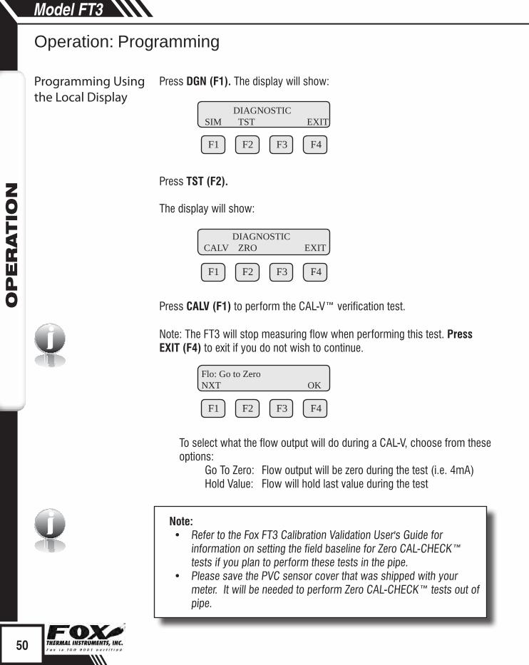
Press DGN (F1). The display will show:
F1 F2 F3 F4
Press TST (F2).
The display will show:
F1 F2 F3 F4
Press CALV (F1) to perform the CAL-V™ verification test.
Note: The FT3 will stop measuring flow when performing this test. Press EXIT (F4) to exit if you do not wish to continue.
F1 F2 F3 F4
To select what the flow output will do during a CAL-V, choose from these options:
Go To Zero: Flow output will be zero during the test (i.e. 4mA)Hold Value: Flow will hold last value during the test
50
Model FT3O
PER
ATIO
N
Operation: Programming
Programming Usingthe Local Display
DIAGNOSTICSIM TST EXIT
DIAGNOSTICCALV ZRO EXIT
Flo: Go to ZeroNXT OK

Select the option and press OK (F4).
F1 F2 F3 F4
WARNING: If you are using a closed loop control, the system needs to be taken off-line during the test.
Press OK (F4) to start CAL-V™. CAL-V™ test screen:
F1 F2 F3 F4 F1 F2 F3 F4
This test will take up to 4 minutes (less time if there is flow) and will show the Cal value changing as the power to the sensor is adjusted. The T=xxx is a count down timer indicating how much time is left to finish the test. A “Please Wait” message will be flashing on and off on line 2 during this test.
Upon test completion, the final CAL-V™ value will be displayed along with a Pass/Fail message.
F1 F2 F3 F4
Zero CAL-CHECK™ - Calibration Validation Test 2The Zero CAL-CHECK™ test is a companion test to CAL-V™. Unlike CAL-V™, which may be performed in the pipe and at process conditions, Zero CAL-CHECK™ must be performed at zero flow to ensure a valid test result. This test is used to confirm that the flow meter still retains its original NIST-traceable calibration at zero flow and that the sensor is free of film or residue that may affect readings. The test takes less than 5 minutes to complete. At the conclusion of the test, a Pass or Fail message will be displayed. Press F4 at the conclusion of the test to return to normal measuring mode or to
51
Model FT3O
PER
ATIO
N
Operation: Programming
Programming Usingthe Local Display
Zero CAL-CHECK™
Take Controloff-line EXIT OK
Verifying CAL-V Please Wait
Verifying CAL-VCal = 12.7 T=123
CAL-V = 0.51Passed OK

terminate the test. See Calibration Validation User's Guide for more details. Press FLO (F2) from the main menu. The display will show:
F1 F2 F3 F4
Press DGN (F1). The display will show:
F1 F2 F3 F4
Press TST (F2). The display will show:
F1 F2 F3 F4
Press ZRO (F2) to enter the Zero CAL-CHECK™ menu.
If performing the test in the pipe, a "no flow" condition must be met. If performing out of the pipe, the meter must be removed and the sensor protected by the PVC sensor cover originally shipped with the meter from the factory.
F1 F2 F3 F4
Press PIP (F1) to choose to perform the test in the pipe. Press BTL (F2) to choose to perform the test out of the pipe.
52
Model FT3O
PER
ATIO
N
Operation: Programming
Programming Usingthe Local Display
FLOW PARAMETER 1DGN UNT PRM EXIT
DIAGNOSTICSIM TST EXIT
DIAGNOSTICCALV ZRO EXIT
ZERO CHK MENU PIP BTL EXIT
i
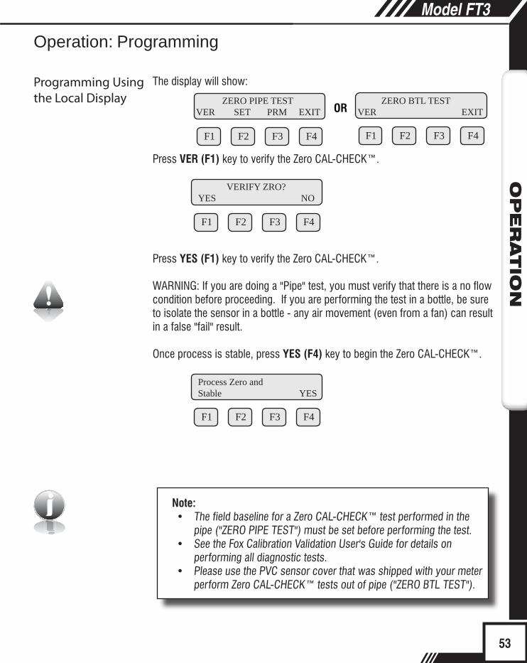
The display will show:
F1 F2 F3 F4
OR
F1 F2 F3 F4
Press VER (F1) key to verify the Zero CAL-CHECK™.
F1 F2 F3 F4
Press YES (F1) key to verify the Zero CAL-CHECK™.
WARNING: If you are doing a "Pipe" test, you must verify that there is a no flow condition before proceeding. If you are performing the test in a bottle, be sure to isolate the sensor in a bottle - any air movement (even from a fan) can result in a false "fail" result.
Once process is stable, press YES (F4) key to begin the Zero CAL-CHECK™.
F1 F2 F3 F4
Note:• The field baseline for a Zero CAL-CHECK™ test performed in the
pipe ("ZERO PIPE TEST") must be set before performing the test.• See the Fox Calibration Validation User's Guide for details on
performing all diagnostic tests.• Please use the PVC sensor cover that was shipped with your meter
perform Zero CAL-CHECK™ tests out of pipe ("ZERO BTL TEST").
53
Model FT3O
PER
ATIO
N
Operation: Programming
Programming Usingthe Local Display ZERO PIPE TEST
VER SET PRM EXIT ZERO BTL TESTVER EXIT
VERIFY ZRO? YES NO
Process Zero and Stable YES

i
F1 F2 F3 F4 F1 F2 F3 F4
This test will take less than 5 minutes. The T=xx is a count down timer indicating how much time is left to finish the test.
F1 F2 F3 F4
Upon test completion, the final percentage value will be displayed along with a Pass/Fail message.
Enabling/Disabling the Infrared Keypad (IR Buttons)The IR buttons may be disabled from the menu to avoid being triggered by frost or snow on the window. This menu is accessed by pressing DSP (F3) from the main menu then IR (F2):
F1 F2 F3 F4
Press NXT (F1) key to enable or disable the IR buttons.
Note: After selecting “Disable” and pressing OK (F4), the IR buttons will no longer operate. It will be necessary from now on to open the cover and operate the configuration panel using the mechanical push buttons. To return to the normal display mode, use mechanical buttons or wait for the programming mode timeout.
Calibrating the Infrared Keypad (IR Buttons)The IR buttons are calibrated in the factory before shipment, but conditions in the field may alter the way the buttons read. To allow the IR buttons to perform better, it may be necessary to calibrate the keys in the field.
54
Model FT3O
PER
ATIO
N
Programming Using the Local Display
Operation: Programming
Enable/Disable IR Buttons
Verifying ZRODiff = xx.xx T=xx
Verifying ZROSd = x.xe-xx T=xx
Diff=x.xxx % Passed OK
IR KEY= EnabledNXT OK
Calibrating IR Buttons

iUse your finger to activate the IR buttons using this process:
Note: Your finger must activate each button approximately 0.1” to .5” from the surface of the glass.
Press the (F1) button until the display shows ‘SET PARAMETER?’ Then use YES (F4).
Use buttons (F1) (F2) and (F3) to enter "1111" (up/down and next).
Use buttons (F1) (F2) and (F3) to enter "0000" then press OK (F4).
Turn OFF power to the FT3.
Turn ON power to the FT3 while placing your finger on the (F1) IR key.
55
Model FT3O
PER
ATIO
NModel FT3
OPER
ATIO
N
Operation: Programming
Calibrating IR Buttons
SET PARAMETERSI/O FLO DSP EXIT
SET I/OCOM I/O 420 EXIT
Comm=HARTNXT OK
NoneModbus
HART
SET I/OINP OUT EXIT
INP= Not usedNXT OK
Not usedTot Reset
SET 4-20 mACH1 CH2 EXIT
20 mACnt=3265CHG OK
4 mACnt=367 CHG OK
20 mA=2345.6 SCFMCHG OK
4 mA=0 SCFMCHG OK
CH2=TempNXT OK
TempFlow
20mACnt=3748CHG OK
4mACnt=274CHG OK
20 mA=300 °FCHG OK
4 mA=0 °FCHG OK
Level 2
Level 2
Analog Outputs
Select either flow or temperature for channel 2
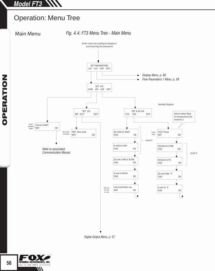
Enter menu by scolling to display 4 and entering the password
mA Fault=Not useNXT OK
Not use3.6 mA21 mA
Display Menu, p. 60Flow Parameters 1 Menu, p. 58
Digital Output Menu, p. 57
Refer to associated Communication Manual
Fig. 4.4: FT3 Menu Tree - Main Menu
56
Model FT3O
PER
ATIO
N
www.foxthermalinstruments.com
Operation: Menu Tree
Digital Output Main Menu

OUT= Not usedNXT OK
Not usedFrequencyHiFloAlmLoFloAlm
HiTempAlmLoTempAlm
FREQUENCY OUTPUTP/U U/P FEQ EXIT
PLS/UNT=2CHG OK
UNT/PLS=0.5CHG OK
MaxFreq=100HzCHG OK
MaxFlo=5678.5 SCFMCHG OK
HiFloAlm=500 SCFMCHG OK
LoFloAlm=100 SCFMCHG OK
HiTmpAlm=300° FCHG OK
LoTmpAlm=10 FCHG OK
High Limit Alarm
Low Limit Alarm
High Temp Alarm
Low Temp Alarm
Select 1 of 3 methods to scale the frequency output
OUT= FREQUENCYNXT OK
Frequency
OUT= HiFloAlmNXT OK
OUT= LoFloAlmNXT OK
OUT= HiTmpAlmNXT OK
OUT= LoTmpAlmNXT OK
Fig. 4.5: FT3 Menu Tree - Digital Output
57
Model FT3O
PER
ATIO
N
399 Reservation Road, Marina, CA 93933 Ph: 831.384.4300 Fax: 831.384.4312
Digital Output
Operation: Menu Tree

FLOW PARAMETER 1DGN UNT PRM EXIT
DIAGNOSTICSIM TST EXIT
FloSim=0 SCFMCHG OK
TmpSim=0 ° FCHG OK
CsvSim=0 VCHG OK
ENABLE SIM?YES NO
Note: simulation value needs to be greater than zero
to be taken(i.e 0.0001 for a value close to
zero)
FLO UNT=SCFMNXT OK
SCFMSCFH
NM3/HNM3/M
KG/HKG/MKG/SLBS/HLBS/MLBS/SNLPHNLPMSMPSNMPSSFPM
MMSCFDLBS/DSLPMNLPS
MSCFDSM3/HMT/H
NM3/DMMSCFM
MCFDSCFD
SM3/MSM3/D
TMP UNT=° FNXT OK
Deg FDeg C
TmpRef= 0 °FCHG OK
PRES UNT=mmHGNXT OK
PresRef=760CHG OK
mmHGPsiabara
STP
Flow Parameter 2 Menu, p. 59
Diagnostic Test Menu, p. 61
Fig. 4.6: FT3 Menu Tree - Parameter Menu 1
58
Model FT3O
PER
ATIO
N
Operation: Menu Tree
Parameter Menu 1

FLOW PARAMETER 2CAL SPC PRM EXIT
Volt1 = 0.2479CHG PRV NXT EXIT
Flo1 = 0.0CHG PRV NXT EXIT
Volt20 = 1.2479CHG PRV NXT EXIT
Flo20 = 7046.5CHG PRV NXT EXIT
K fact = 0%CHG OK
RESTORE DATABASE?YES NO
RESET CRC?YES NO
Cutoff=12.5 SCFMCHG OK
A2=0.0233CHG OK
Filter=0.8CHG OK
HiFloAlm=0 SCFMCHG OK
LoFloAlm=0 SCFMCHG OK
HiTempAlm=0 °FCHG OK
LoTempAlm=0 °FCHG OK
Level 2
Level 2Calibration Table Parameters
Flow cutoff in selected units
Pipe Area in m² or ft²
Flow Exponential Filter
High Flow Alarm in selected units
Low Flow Alarm in selected units
High Temperature Alarm in selected units
Low Temperature Alarm in selected units
velocity in Meter/hour for point #1
sensor voltage for point #1
CAL TABLETB1 (TB2) (TB3) EXIT
Cycle throughup to 20 settings
Level 1
Fig. 4.7: FT3 Menu Tree - Parameter Menu 2
59
Model FT3O
PER
ATIO
N
Parameter Menu 2
Operation: Menu Tree

DISPLAY/PASSWORDDSP IR PSW EXIT
DSP1L1=FLo rateNXT OK
FLo rateTotalElps
TempAlarm
DSP1L2=TempNXT OK
DSP2L1=AlarmNXT OK
DSP2L2=ElpsNXT OK
ALTERNATE=OffNXT OK
OnOff
PASSWD=1234CHG OK
FLo rateTotalElps
TempAlarm
FLo rateTotalElps
TempAlarm
FLo rateTotalElps
TempAlarm
When alternate "ON", flashes between the 2 displays
Display 1 Line 1
Display 1 Line 2
Display 2 Line 1
Display 2 Line 2
IR KEY=EnabledNXT OK
EnabledDisabled
Note:All readings updated every second• Flo Rate = Flow rate of process gas• Total = Total flow of process gas• Elps = Elapsed time since reset of flow total• Temp = Temperature of process gas• Alarm = High/Low Flow Rate or Temperature Alarm
i
Fig. 4.8: FT3 Menu Tree - Display Menu
60
Model FT3O
PER
ATIO
N
60
Model FT3O
PER
ATIO
N
Operation: Menu Tree
Display Menu

ZERO PIPE TESTVER SET PRM EXIT
SET ZRO Ref?YES NO
VERIFY ZRO?YES NO
Level 1
Process Zero andStable? EXIT YES
Verifying ZRODiff=x.xx T=xx
Diff=x.xxx %Pass OK
Process Zero andStable? EXIT YES
Setting ZRO refZR=x.xxxxx T=xx
Ref=x.xxxxOK
Level 2
Display alternates between
the 2 screens
Displays count down timer
(T=xx)
Displays“Pass” or
“Fail”
Test=300 secCHG OK
ZERO CHK MENUPIP BTL EXIT
DIAGNOSTICCALV ZRO EXIT
Verifying CAL-VCal=xxx T=yyy
Verifying CAL-VPlease Wait
CAL-V=0.51Pass OK
Display alternates between the 2
screens until the test is completed
in about 4 minutes. Pressing
the F4 key will abort the test
“Pass” or ”Fail” result is displayed at end of test.
CAL VER EXIT
Flo:Go to zeroNXT EXIT OK
Hold ValueGo to zero
Take Controloff-line EXIT OK
Level 2
Level 1
Verifying ZROSd=x.xe-xx T=xx
ZERO BTL TESTVER EXIT
VERIFY ZRO?YES NO
Level 1
Process Zero andStable? EXIT YES
Verifying ZRODiff=x.xx T=xx
Diff=x.xxx %Pass OK
Display alternates between
the 2 screens
Displays “Pass” or “Fail”
Verifying ZROSd=x.xe-xx T=xx
Flow Parameter 1 Menu, p. 58
Fig. 4.9: FT3 Menu Tree - Diagnostic Tests Menu
61
Model FT3O
PER
ATIO
N
61
Model FT3O
PER
ATIO
N
Diagnostic Tests Menu
Operation: Menu Tree

GB
ES
WARNING! BEFORE ATTEMPTING ANY MAINTENANCE, TAKE THE NECESSARY SAFETY PRECAUTIONS BEFORE REMOVING THE PROBE FROM THE DUCT (EXAMPLE: PURGE LINES OF TOXIC AND/OR EXPLOSIVE GAS, DEPRESSURIZE, ETC...).
WARNING! EXPLOSION HAZARD. DO NOT REMOVE OR REPLACE COMPONENTS OR FUSES UNLESS POWER HAS BEEN DISCONNECTED WHEN A FLAMMABLE OR COMBUSTIBLE ATMOSPHERE IS PRESENT.
WARNING! EXPLOSION HAZARD. DO NOT DISCONNECT EQUIPMENT WHEN A FLAMMABLE OR COMBUSTIBLE ATMOSPHERE IS PRESENT.
WARNING! TURN OFF INPUT POWER BEFORE REMOVING OR INSTALLING A CIRCUIT BOARD ASSEMBLY FROM THE ENCLOSURE.
Access to ElectronicsAccessing electronics is not normally required for maintenance purposes. If a loose connection is suspected, unscrew the rear end-cap of the meter enclosure to access the terminations
CAUTION: BE SURE POWER TO METER IS SWITCHED OFF BEFORE ATTEMPTING TO ACCESS ELECTRONICS. If there is a problem and a loose connection is not found, please contact Fox Customer Service for technical assistance at (831) 384-4300.
¡ADVERTENCIA! ANTES DE INTENTAR CUALQUIER MANTENIMIENTO, TOME LAS PRECAUCIONES DE SEGURIDAD NECESARIAS ANTES QUE RETIRAR LA SONDA DEL DUCTO (EJEMPLO: PURGUE LAS LÍNEAS DE GASES TÓXICOS Y/O EXPLOSIVOS, DESPRESURICE, ETC...).
¡ADVERTENCIA! PELIGRO DE EXPLOSIÓN. NO RETIRE O REEMPLACE COMPONENTES O FUSIBLES A MENOS QUE LA ENERGÍA HAYA SIDO DESCONECTADA SIEMPRE QUE ESTÉ PRESENTE UNA ATMÓSFERA INFLAMMABLE O COMBUSTIBLE.
¡ADVERTENCIA! PELIGRO DE EXPLOSIÓN. NO DESCONECTE NINGÚN EQUIPO CUANDO UNA ATMÓSFERA INFLAMABLE O COMBUSTIBLE ESTÉ PRESENTE PRONTO.
¡ADVERTENCIA! DESCONECTE LA ENERGÍA DE ALIMENTACIÓN ANTES DE REMOVER O INSTALAR UN ENSAMBLE DE TARJETA DE CIRCUITO DEL GABINETE.
Acceso a la ElectrónicaNormalmente no se requiere tener acceso a la electrónica para propósitos de mantenimiento. Si se sospecha de una conexión suelta, desatornille la tapa posterior de la caja del medidor para tener acceso a las terminales
PRECAUCIÓN: ASEGÚRESE QUE LA ALIMENTACIÓN DEL MEDIDOR ESTE DESCONECTADA ANTES DE INTENTAR EL ACCESO A LA ELECTRÓNICA. Si existe algún problema y no se encuentra ninguna conexión suelta, por favor póngase en contacto con el Servicio al Cliente de Fox para asistencia técnica al número (831) 384-4300.
62
Model FT3M
AIN
TEN
AN
CE
Precautions
Maintenance: Precautions
Precauciones
Précautions

AVERTISSEMENT ! AVANT TOUTE TENTATIVE DE MAINTENANCE, OBSERVER LES CONSIGNES DE SECURITE NECESSAIRES AVANT DE RETIRER LA SONDE DE LA CONDUITE (PAR EXEMPLE, PURGER LES LIGNES DES GAZ EXPLOSIFS/TOXIQUES QU’ELLES POURRAIENT CONTENIR, DEPRESSURISER LE CONTENEUR, ETC.).
AVERTISSEMENT ! RISQUE D’EXPLOSION. NE PAS RETIRER NI REMPLACER DES COMPOSANTS OU DES FUSIBLES SI LA SOURCE D’ALIMENTATION N’A PAS ETE DEBRANCHEE DANS UNE ATMOSPHERE INFLAMMABLE OU COMBUSTIBLE.
AVERTISSEMENT ! RISQUE D’EXPLOSION. NE PAS DEBRANCHER UN EQUIPEMENT DANS UNE AMBIANCE COMBUSTIBLE OU INFLAMMABLE.
AVERTISSEMENT ! COUPER L’ALIMENTATION AVANT DE RETIRER OU D’INSTALLER UN ENSEMBLE DE CARTE DE CIRCUITS IMPRIMES DU BOITIER.
Accès aux composants électroniquesL’accès aux composants électroniques n’est généralement pas nécessaire dans le cadre de la maintenance. Si une connexion lâche est suspectée, dévisser le capuchon d’extrémité arrière du boîtier du compteur pour accéder aux terminaisons
ATTENTION : S’ASSURER QUE L’ALIMENTATION DU COMPTEUR EST COUPEE AVANT D’ACCER AUX COMPOSANTS ELECTRONIQUES. En cas de problème et qu’aucune connexion lâche n’est détectée, veuillez contacter le service client de Fox pour obtenir une assistance technique au (831) 384-4300.
ACHTUNG! BITTE ERGREIFEN SIE DIE ERFORDERLICHEN SICHERHEITSMAßNAHMEN, BEVOR SIE IRGENDWELCHE WARTUNGSARBEITEN DURCHFÜHREN UND DIE MESSSONDE AUS DEM ROHR ENTFERNEN (BEISPIEL: LEITUNGEN ZUR ENTFERNUNG VON GIFTIGEN UND/ODER EXPLOSIVEN GASEN REINIGEN, DRUCK SENKEN, USW.).
ACHTUNG! EXPLOSIONSGEFAHR. KOMPONENTEN ODER SICHERUNGEN BITTE ERST DANN ENTFERNEN ODER AUSTAUSCHEN, WENN DER STROM GETRENNT WURDE, FALLS EINE ENTZÜNDLICHE ODER BRENNBARE ATMOSPHÄRE VORHANDEN IST.
ACHTUNG! EXPLOSIONSGEFAHR. GERÄT NICHT VOM STROM TRENNEN, WENN EINE ENTZÜNDLICHE ODER BRENNBARE ATMOSPHÄRE VORHANDEN IST.
ACHTUNG! EINGANGSLEISTUNG AUSSCHALTEN, BEVOR LEITERPLATTENBAUGRUPPEN AUS DEM GEHÄUSE AUSGEBAUT ODER IN DIESES EINGEBAUT WERDEN.
Zugriff auf die ElektronikDer Zugriff auf die Elektronik ist zu Wartungszwecken normalerweise nicht erforderlich. Falls eine lose Verbindung vermutet wird, schrauben Sie die hintere Endkappe des Messgerätgehäuses ab, um auf die Anschlüsse zugreifen zu können.
VORSICHT: STELLEN SIE SICHER, DASS DER STROM AN DAS MESSGERÄT AUSGESCHALTET IST, BEVOR SIE VERSUCHEN, AUF DIE ELEKTRONIK ZUZUGREIFEN. Falls Probleme auftreten und keine lose Verbindung gefunden werden kann, wenden Sie sich bitte zwecks technischer Unterstützung an den Fox-Kundendienst unter der Nummer (831) 384-4300.
63
Model FT3M
AIN
TEN
AN
CE
Maintenance: PrecautionsPrecautions
FRPrécautions
DEVorsichtsmaßnahmen

i
64
Model FT3M
AIN
TEN
AN
CE
www.foxthermalinstruments.com
Maintenance: General
Broken or Damaged ProbeIf the sensor is broken or damaged, the probe and electronics must be returned to the factory. A new sensor will be installed and calibrated. Refer to "Returning Your Meter" on p. 92.
Flow Calibration and Calibration ValidationTo ensure continued high accuracy of your Model FT3 Flow Meter, Fox Thermal Instruments Inc. provides a full NIST traceable calibration. It is recommended that the meter be returned to Fox for a calibration check in our NIST traceable labs after two years of operation.
Fuse ReplacementVerify the fuse is defective by measuring it with an Ohm Meter (Two replacement fuses are provided with each unit). The fuse F1 is located near the power terminal block and can be removed by using tweezers or needle-nose pliers. Replacement fuse is Littelfuse part number 0454.750MR.
Warning:• Turn input power OFF before removing or installing a fuse. Use only recommended
fuse replacements.• It is the user’s responsibility to install the flow meter in an appropriately designed
system with adequate safety protections. • DO NOT remove the flow instrument from the flow body while the system is under flow
conditions. • This product may experience temperatures from as low as -40F (-40C) and as high
as 649F (343C). It is the user’s responsibility to take safety precautions regarding operating temperature of the flow meter.
• If large flow body has been purchased, user is advised to use a double sling to prevent rotation of flow body during installation or other method to prevent damage of flow instrument.
Sensor WiringNote: Sensor terminations are performed at the factory except when the Remote Electronics option is used or ordered.
Sensor CleaningThe sensor is insensitive to small amounts of residue, but continued use in dirty environments will necessitate periodic cleaning. To inspect the sensor, remove power from electronics and remove the unit from the pipe or duct, exposing the sensor elements. If they are visibly dirty, clean them with water or alcohol (ethanol) using an appropriate brush until they appear clean again. Even though the sensor elements are rugged, avoid touching them with any solid object and use a light touch while cleaning them.

Problem Possible Cause Action
Display-Main BdComm. Error
Display and main board not communicating
Check status of LP1 on the Main Board and LP6 on the display board. Are green LEDs blinking once per second? If LEDs are not blinking, cycle power to reset meter. Call Fox Tech Support.
Meter does not read up to full scale
Calibration table may be corrupted
•Check the calibration table for a corrupted location. •Enter the password 9111. •Start on p. 41 of the FT3 manual and follow the steps to get to Flow Parameters 2 menu screen. •Select CAL (F1) •Select NXT (F1) to cycle through calibration table to verify entries match calibration certificate.•Check for CRC error code
Velocity measurement seems low
1.Probe not oriented properly
2.Sensor dirty
1.Orient probe per installation sections: Insertion (p. 9), Inline (p. 13).
2.Clean sensor (p. 64)
TroubleshootingCaution! The electronics, sensor and sensor interconnect wires supplied by Fox are calibrated as a single precision mass flow meter. Interchanging sensors or sensor wiring will impair the accuracy of the flow meter. If you experience any problem with your Model FT3 Flow meter, call Fox Customer Service Department, Technical Assistance at (831) 384-4300.
65
Model FT3TR
OU
BLES
HO
OTIN
G
399 Reservation Road, Marina, CA 93933 Ph: 831.384.4300 Fax: 831.384.4312
Troubleshooting: General
Troubleshooting

Problem Possible Cause Action
Unit will not power-up a)No power inputb)Bad fusec)Bad Power supply
•Check fuse (F1) located next to TS1 on main board.•Check for correct power supply voltage at TS1 on main board.
If fuse is OK and unit still won’t power up, call Fox for additional assistance
Meter does not initialize Electromechanical interference •Check meter power cycles.•Press and release F1 and F2 at the same time; the display will enter Engineering screens.•Press F1 to get to screen #23; record power cycle value. •Press F4 to return to normal operation; monitor meter until problem returns. •Return to screen #23 to see if power cycles have increased; microprocessor is resetting due to EMI electrical noise entering the meter. •Check Power input and output cables grounding and routing.
66
Model FT3TR
OU
BLES
HO
OTIN
G
66
Model FT3
Troubleshooting: General

Problem Possible Cause Action
Velocity measurement is erratic or fluctuating
1.Very turbulent flow
2.Sensor dirty
3.Sensor broken
4.Probe not mounted securely
5.Malfunction in flow meter
6.Meter installed incorrectly
1.Increase dampening (see filter settings in "Flow Param-eters" on p. 41)
2.Clean sensor (Refer to Maintenance section, p. 64)
3.Return flow meter to Fox for repair (Refer to p. 92 for shipping instructions)
4.Remount probe (see Instal-lation section, p. 9 and p. 13); must be mounted securely without vibration. If vibration persists, choose a new mounting location with-out location.
5.Return flow meter to Fox for repair (Refer to p. 92 for shipping instructions)
6.Re-install meter accord-ing to instructions (Refer to installation section, p. 9 and p. 13)
67
Model FT3TR
OU
BLES
HO
OTIN
G
67
Model FT3
Troubleshooting: Installation Problems

Installation ProblemsThe following is a summary listing of problems that may be encountered with the installation of the FT3 Thermal Mass Flow Meter.
1. Improper wiring connections for power and/or 4 to 20mA output signal. The FT3 requires a separate power source for the main board and the two 4 to 20mA output signals. Two wires supply 24VDC power to the main board. Two wires are used for each of the 4 to 20mA output signals. Refer to Figure 3.4 and Figure 3.5 (p. 17). Also refer to "Wiring Precautions" and "Helpful Hints" in Wiring section (p. 15) for further guidance.
2. Inadequate power source. For those models that are powered by 24VDC, a 24VDC ±10%, 0.7 Amp or greater power supply is recommended. If the voltage supplied is not within this range or if the power supply is not rated for 25 watts minimum, a variety of problems can occur including inaccurate flow readings, dim display and faulty programming action. The input voltage must be within the range of 21.6 to 26.4VDC as measured at the power input terminals of the flow meter electronics.
3. Flow measurement seems inaccurate.• Check to ensure that the flow meter is installed so that the Flow
Direction Arrow engraved on the flat surface of the fitting below the electronics housing is properly pointing in the direction of flow. Refer to Figure 2.7 (p. 13). If not, change orientation of meter.
• If you have a Fox insertion type flow meter, check that the insertion depth of the sensor/probe is correct. The end of the probe should be adjusted as per Figure 2.2 (p. 10).
• For inline meter types, ensure that there are a minimum of ten diameters of straight pipe upstream of the sensor and five diameters downstream (¼" meters: 6” [152 mm] of straight, unobstructed pipe upstream and downstream required). For insertion meter types, ensure that there are a minimum of fifteen diameters of straight pipe upstream of the sensor and ten diameters downstream. If complex flow disturbances are upstream of the sensor, extension of the straight pipe may be required to ensure accurate flow measurement. Contact Fox for assistance.
• Ensure that pipe area data in the meter matches data on the Fox Calibration Certificate. The pipe internal cross sectional area is programmed into the flow meter through the front panel (see Flow
68
Model FT3TR
OU
BLES
HO
OTIN
G
68
Model FT3
68
Model FT3
Troubleshooting: Installation Problems
Installation Problems

Parameters, p. 41). This area is programmed in square feet or square meters. The Calibration Certificate delivered with the flow meter contains the area that was programmed into the flow meter at the Fox factory. Check to ensure that this area is correct.
4. Erratic flow reading especially a flow reading spiking high. This may be a symptom of moisture in the flow stream. Fox flow meters are designed to work in relatively dry gas applications only. Contact Fox to discuss resolutions to this problem.
5. Flow meter is not responding to flow. This problem could be caused by a number of reasons: • Check to ensure adequate power is supplied to the flow meter as
described above. If things appear to be correct, an easy functional test can be performed. Carefully remove the probe and sensor from the pipe or flow body. Caution: the sensor is HOT. For those flow meters with a display - and if the display is reading zero - blow on the sensor to see if a response occurs. If nothing happens, take a damp rag or sponge and place it in contact with the sensor. A reading should occur. Contact Fox Customer Service with this information.
• A corrupted calibration table may lead to a zero flow reading. Verify that all Cal Flow Parameter settings are correct by accessing the "Calibration Parameters" information on meter (see p. 45). Check meter data for any non-whole numbers and call customer service for assistance.
6. Display and/or 4 to 20mA signal reading above zero flow when no flow is occurring in the pipe.If the reading is less than 5% of full scale, it is likely this is a normal condition caused by convection flow created by the heated sensor. It does not mean that the zero of the instrument is improperly set. The Fox sensor is extremely sensitive to gas flow and can even read the small flow caused by convection. If this is an unacceptable condition, please contact Fox Customer Service for alternatives.
7. Mismatched serial numbersIf you have more than one meter, you must ensure that the serial numbers of meter, remote, and/or flow body match one another. These items have been manufactured and calibrated to operate as a unit and cannot be mismatched.
69
Model FT3TR
OU
BLES
HO
OTIN
G
69
Model FT3TR
OU
BLES
HO
OTIN
G
Troubleshooting: Installation Problems
Installation Problems
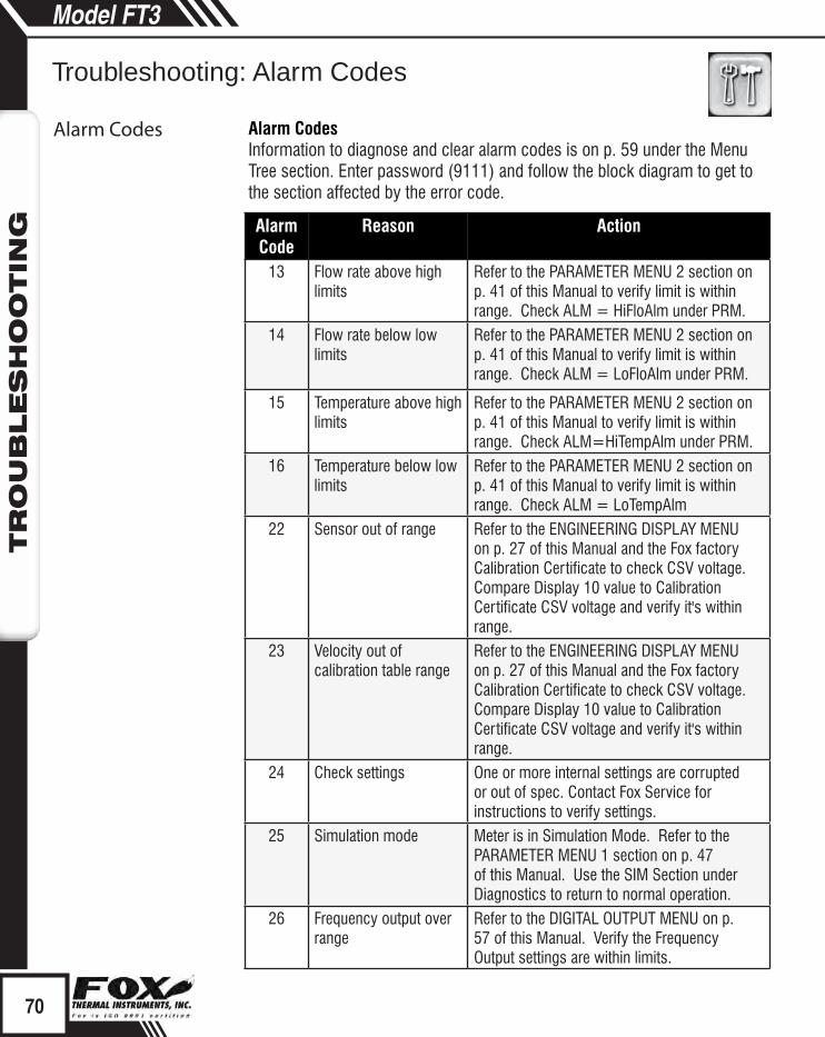
Alarm Code
Reason Action
13 Flow rate above high limits
Refer to the PARAMETER MENU 2 section on p. 41 of this Manual to verify limit is within range. Check ALM = HiFloAlm under PRM.
14 Flow rate below low limits
Refer to the PARAMETER MENU 2 section on p. 41 of this Manual to verify limit is within range. Check ALM = LoFloAlm under PRM.
15 Temperature above high limits
Refer to the PARAMETER MENU 2 section on p. 41 of this Manual to verify limit is within range. Check ALM=HiTempAlm under PRM.
16 Temperature below low limits
Refer to the PARAMETER MENU 2 section on p. 41 of this Manual to verify limit is within range. Check ALM = LoTempAlm
22 Sensor out of range Refer to the ENGINEERING DISPLAY MENU on p. 27 of this Manual and the Fox factory Calibration Certificate to check CSV voltage. Compare Display 10 value to Calibration Certificate CSV voltage and verify it's within range.
23 Velocity out of calibration table range
Refer to the ENGINEERING DISPLAY MENU on p. 27 of this Manual and the Fox factory Calibration Certificate to check CSV voltage. Compare Display 10 value to Calibration Certificate CSV voltage and verify it's within range.
24 Check settings One or more internal settings are corrupted or out of spec. Contact Fox Service for instructions to verify settings.
25 Simulation mode Meter is in Simulation Mode. Refer to the PARAMETER MENU 1 section on p. 47 of this Manual. Use the SIM Section under Diagnostics to return to normal operation.
26 Frequency output over range
Refer to the DIGITAL OUTPUT MENU on p. 57 of this Manual. Verify the Frequency Output settings are within limits.
Alarm CodesInformation to diagnose and clear alarm codes is on p. 59 under the Menu Tree section. Enter password (9111) and follow the block diagram to get to the section affected by the error code.
70
Troubleshooting: Alarm Codes
Model FT3TR
OU
BLES
HO
OTIN
G
Troubleshooting: Alarm Codes
Alarm Codes

Alarm Code
Reason Action
32 4 to 20mA for flow rate is out of range
Refer to the MAIN MENU on p. 56 of this Manual. Use the Set I/O section to verify range limits under FLO Set 4 to 20mA.
33 4 to 20mA for temperature is out of range
Refer to p. 44 of this Manual. Use the Set I/O section to verify range limits under FLO Set 4 to 20mA. Channel #2 can be set for flow or temperature.
34 Busy Meter is recalculating new parameters.
35 Sensor Bridge Shutdown
The FT3 probe is getting too hot. Open sensor circuit and check sensor wiring.
36 Database CRC Error Refer to the PARAMETER MENU 2 section on p. 41 of this Manual to reset CRC. Use SPC section of menu to reset CRC. Contact Fox Service Department for possible causes.
37 Totalizer Error Detected See "Reset the Total and Elapsed Time" on p. 46 for steps to clear Error Code. Contact Fox for possible causes.
38 CAL-V in progress Wait until the CAL-V or Cal Set is finished.
39 ADC12 versus ADC24 too far
The tolerance between the 2 ADC is out of specification. Recalling manufacture default may correct the problem.
40 CAL-V Diff Fail The CAL-V Diff Failed. Check sensor wiring and verify that the sensor's resistance is correct. Call Tech Support.
41 Zero CAL-CHECK Fail Allow meter to stabilize for 15 minutes and perform the test again. If another "Fail" test results, call Tech Support.
71
Troubleshooting: Alarm Codes
Model FT3TR
OU
BLES
HO
OTIN
G
Alarm Codes

Performance SpecsFlow Accuracy:
Inline Meter: ± 1% of reading ± 0.2 % of full scale. ¼" size: 6” (152 mm) of straight, unobstructed pipe upstream and downstream required.All other sizes: 8 diameters of straight, unobstructed pipe upstream and 4 downstream required.
Insertion Meter: ± 1% of reading ± 0.2 % of full scale. 15 diameters of straight, unobstructed pipe upstream and 10 downstream required.
Flow Repeatability: ± 0.2% of full scale
Flow Response Time: 0.9 seconds (one time constant)
Temperature Accuracy:± 1.8° F (± 1.0° C) -40 to 250° F (-40 to 121° C); ± 3.6° F (± 2.0° C), 250 to 650° F (121 to 343° C); 60 SFPM minimum.
Calibration:Factory Calibration to NIST traceable standardsCAL-V™ & Zero CAL-CHECK™: In situ, operator-initiated calibration validation
Operating SpecsUnits of Measurement (field selectable): SCFM, SCFH, NMPS, NM3/M, NM3/H, NM3/D, NLPS, NLPM, NLPH, SCFD, MSCFD, MMSCFD,
MMSCFM, SMPS, SM3/D, SM3/H, SM3/M, LB/S, LB/M, LB/H, LB/D, KG/S, KG/M, KG/H, SLPM, SFPM, MT/H, MCFD
Flow Rates for Insertion Flow Meter: 15 to 60,000 SFPM (0.07 to 280 NMPS) - Air at 70°F (20°C) & 1 ATM Turndown: up to 1000:1; 100:1 typical
Typical Flow Ranges for Insertion Flow MetersPipe size SCFM NM3/hr
1.5" (40mm) 0-840 0-1,3202" (50mm) 0-1,400 0-2,2003" (80mm) 0-3,080 0-4,8604" (100mm) 0-5,300 0-8,3606" (150mm) 0-12,000 0-18,9008" (200mm) 0-20,800 0-32,80012" (300mm) 0-46,600 0-73,500
72
Appendices: Specifications
Model FT3APPEN
DIC
ES

Full Scale Flow Ranges for In-Line Flow meters:
Size SCFM NM3/hr0.25" 0-20 0-320.5" 0-90 0-1400.75" 0-180 0-280
1" 0-320 0-5001.25" 0-580 0-9101.5" 0-840 0-1,3202" 0-1,400 0-2,200
2.5" 0-2,000 0-3,1503" 0-3,080 0-4,8604" 0-5,300 0-8,3606" 0-12,000 0-18,900
Note: Standard conditions of air at 70°F and one atmosphere. Consult factory for other gases and for flow ranges above those listed. Inline meters above 5,000 SCFM (7,900 NM3/H) air may require third party Calibration. Contact Fox.
Gas Pressure (maximum): Insertion: 500 psig (34.5 barg) Inline (1/4" through 6"): NPT 500 psig (34.5 barg); 150# flange 230 psig (16 barg) Check with factory for higher pressure options.
Note: Pressure ratings stated for temperature of 100°F (38°C).
Relative Humidity: 90% RH maximum; non-condensing
Maximum Altitude: 6,562ft (2,000m) max.
Temperature: ST sensor: -40 to 250°F (-40 to 121°C)
HT Sensor: -40 to 650°F (-40 to 343°C) Enclosure:
Without display or AC power supply: -40 to 158°F (-40 to 70°C)With display and/or AC power supply: -4 to 158°F, (-20 to 70°C) Remote sensor junction box: -40 to 212°F (-40 to 100°C).
Input Power:24 VDC (± 10%), 0.7 Amps (standard DC power) 100 to 240VAC~(+10%/-15%), 50-60Hz, 0.2 Amps (with AC power option)
Note: Fluctuations of AC and DC power supply are not to exceed ± 10% of rating.
— – – –
73
Appendices: Specifications
Model FT3APPEN
DIC
ES

Class I Equipment (Electrical Grounding Required for Safety). Installation (Over-voltage) Category II for transient over-voltages.
Outputs:
Two isolated 4 to 20mA outputs (output one is for flow rate and output two is programmable for flow rate or temperature); fault indication per NAMUR NE43.
Isolated pulse output 0 to 100Hz, 5 to 24 volts p/p for flow (the pulse output can be used as an isolated solid state output for alarms); 10mA max.
Serial Communication:
USB communication port is standard. The free PC-based software tool - FT3 View™ - provides complete configuration, remote process monitoring, and data logging functions.
Optional serial communication: HART and RS485 Modbus.
4 to 20mA Loop Verification: Simulation mode used to align 4 to 20mA output with the input to customer’s PLC/DCS.
Physical SpecsSensor material: 316 stainless steel standard; Hastelloy C276 optional
Enclosure:NEMA 4X (IP67), aluminum, dual conduit entries with ¾” NPT or optional M20 x 1.5mm. Cabling to remote enclosure: 5-conductor, 18 AWG, twisted, shielded, 100 feet maximum.
Retractor Assemblies: Packing gland assembly: 125 psig (8.6 barg ) max. High pressure (crank) retractor: NPT 600 psig (41.4 barg), ANSI 150 flange & ANSI 300 flange, no valve supplied.
Insertion Flow Meter Installation: Fox-supplied compression fitting connects to customer-supplied ¾” female coupling welded to pipe.
Agency ApprovalsCE: Approved
EMC Directive; 2004/108/ECEmissions and Immunity Testing: EN61326-1:2008Low Voltage Directive (LVD): 2006/95/ECProduct Safety Testing: EN 61010-1: 2010Pressure Equipment Directive: 97/23/ECWeld Testing: EN ISO 15614-1 and EN ISO 9606-1, ASME B31.3
74
AppendicesSection 1
Model FT3APPEN
DIC
ES
Appendices: Specifications

FM and FMc: ApprovedClass I, Div. 1, Gps B, C, D; Class II, Div. 1, Gps E, F, G; Class III, Div. 1; T3C, Ta = -40°C to 70°C; Class I, Zone 1, AEx/Ex d IIB+H2 (T6, T4, or T1*); Ta = -20°C to 70°C; Type 4X (IP67)
ATEX (FM12ATEX0034X): ApprovedII 2 G Ex d IIB+H2 (T6, T4, or T1*) Gb Ta = -20°C to 70°C; IP67II 2 D Ex tb IIIC (T85°C, T135°C, or T450°C*) Db Ta = -20°C to 70°C; IP67
IECEx (IECEx FMG 12.0010X): ApprovedEx d IIB+H2 (T6, T4, or T1*) Gb Ta = -20°C to 70°C; IP67Ex tb IIIC (T85°C or T135°C*) Db Ta = -20°C to 70°C; IP67**
ATEX and IECEx Standards:EN 60079-0: 2009 IEC 60079-0: 2011EN 60079-1: 2007 IEC 60079-1: 2007EN 60079-31: 2009 IEC 60079-31: 2008EN 60529: 1991, +A1: 2000 IEC 60529: 2001
Model Code Temperature Code Marking (Gas)
Temperature Code Marking (Dust)
Enclosure Sensor Type Main Enclosure
Remote Enclosure
Main Enclosure
Remote Enclosure**
E1 ST T4 N/A 135°C N/AE2 ST T4 N/A 135°C N/AE3 ST T6 T4 85°C 135°C**E4 ST T6 T4 85°C 135°C**E3 HT T6 T1 85°C 450°C**E4 HT T6 T1 85°C 450°C**
*Temperature code ratings for Zones are dependent on external process temperature factors and equipment enclosure configuration. See the table above for specific temperature code ratings.**The IECEx dust rating does not apply to the Remote Enclosure.
Note: The EU Pressure Equipment Directive (PED) requires that the minimum ambient and fluid temperature rating for carbon steel flow bodies not be below -29C.
75
Appendices
Model FT3APPEN
DIC
ES
Appendices: Agency Approvals

F1 F2 F3 F4
F1 F2 F3 F4
F1 F2 F3 F4
SWITCH TO CRV 1? NO YES
PASSWORD:_ UP DN NXT OK
SWITCH TO CRV 1
76
AppendicesSection 1
Model FT3APPEN
DIC
ES
: FT3 with 2 Gas Curves
Scope ScopeThis section describes added features to the standard FT3 flow meter when using the 2 gas curves firmware option.
FT3 2 Gas CurvesThe 2 Gas Curves firmware allows the use of two different calibration tables when running with different gases. One of two methods can be used to switch between the two calibration curves:
1) Use of Contact Input:When the contact input is programmed for curve switching, an open contact will select curve #1 and a contact closure will select curve #2.
2) Use of the Keypad:If the contact input is not programmed for curve switching, pressing F2 and F3 simultaneously will prompt an operator to manually switch curve upon entering a password and confirming the action by pressing the appropriate key.
Pressing F2 & F3 simultaneously:
Password needs to be entered if active (default: 1234):
After entering a valid password, a brief confirmation message will be displayed for 1 second:
FT3 2 Gas Curves

F1 F2 F3 F4
i
INP=SWITCH CRV NXT OK
77
AppendicesSection 1
Model FT3APPEN
DIC
ES
: FT3 with 2 Gas Curves
FT3 2 Gas Curves
3) Programming Contact Input for Curve Switching:Enter the menu using steps outlined in "Discrete Input Settings" section (p. 34) and select "Switch CRV". Please note that the flow meter needs to be programmed for 2 gas curves at the Fox factory before you can select this function. Flow meters are shipped with pre-programmed user requested settings.
Selections are: "Not used" "Tot Reset" "Switch Crv"
Helpful Hint:From normal display mode, press F4 to view the current gas curve selection.

F1 F2 F3 F4
F1 F2 F3 F4
F1 F2 F3 F4
F1 F2 F3 F4
DNS1 = 0.9876 CHG OK
DNS2 = 1.2876 CHG OK
20mA = 500SCFM CHG OK
4mA = 0 CHG OK
78
AppendicesSection 1
Model FT3APPEN
DIC
ES
: FT3 with 2 Gas Curves
4) Programming Densities for Curve 1 and Curve 2:When the selected flow unit is mass/time, two different densities will be used for each curve if the meter has been programmed for 2 gas curves. To change the densities:
Go to the unit menu following "Unit Settings" section.
DNS1 is the density associated with curve 1. Change it as needed and press OK.
DNS2 is the density associated with curve 1. Change it as needed and press OK.
5) Programming 4 to 20mA settings for Curve 1 and Curve 2:When the meter has been programmed for 2 gas curves, 2 sets of 4 to 20mA settings for flow rate are used. To program these settings:
Go to the 4 to 20mA setting following the "Analog 4 to 20mA Settings" section.
20mA is the upper limit associated with curve 1. Change it as needed and press OK.
4mA is the lower limit associated with curve 1. Change it as needed and press OK.
FT3 2 Gas Curves

F1 F2 F3 F4
F1 F2 F3 F4
20 maCv2=450 SCFM CHG OK
4 maCv2=0 CHG OK
79
AppendicesSection 1
Model FT3APPEN
DIC
ES
: FT3 with 2 Gas Curves
20 maCv2 is the upper limit associated with curve 2. Change it as needed and press OK.
4 maCv2 is the lower limit associated with curve 2. Change it as needed and press OK.
6) Operation:• To avoid confusion, only one of two techniques is enabled. If the contact
input is assigned to switch gas curves, then the ability to switch using the F2 and F3 function keys on the front panel is disabled.
• Two totalizers (Total 1 and Total 2) and two elapsed time counters are available on the display and through the USB serial communication. The reset function will reset all totalizers and elapsed time counter to zero.
• In the event of a power failure, the software will remember the last curve in use. Upon powering up again, the FT3 unit will continue to use that curve.
• Switching between gas curves will require a password unless the password is set to "0", which disables it.
• The calibration certificates for order with 2 gas curves will identify which gas is Gas 1 and Gas 2.
• When measuring in mass units, a density value must be entered for each gas curve.
FT3 2 Gas Curves
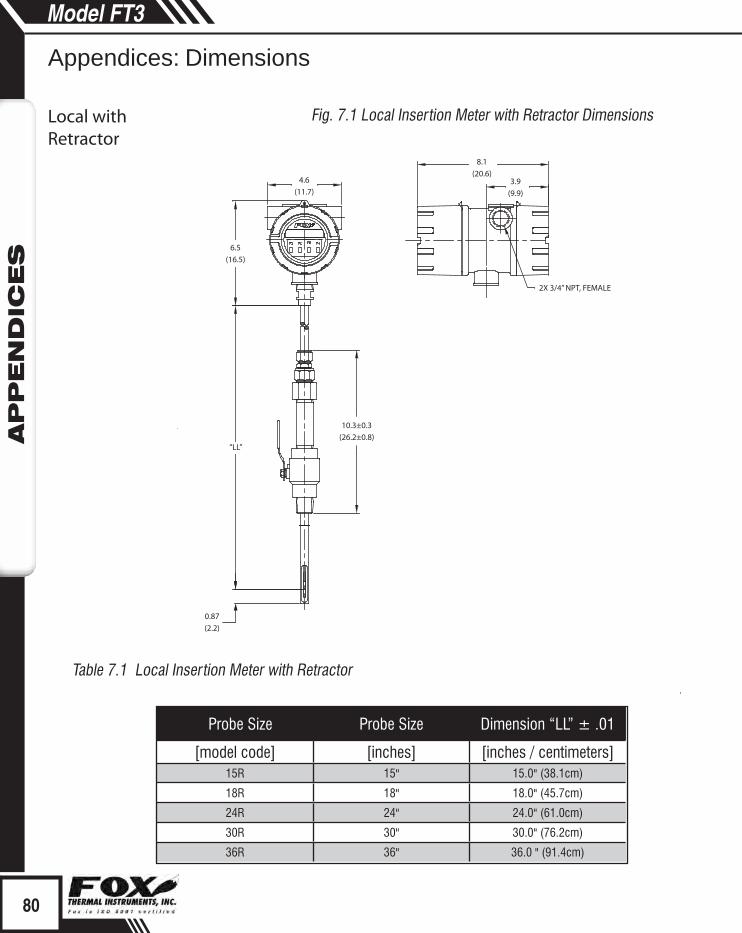
4.6(11.7)
3.9(9.9)
8.1(20.6)
2X 3/4” NPT, FEMALE
“LL”
10.3±0.3(26.2±0.8)
6.5(16.5)
0.87(2.2)
80
AppendicesSection 1
Model FT3APPEN
DIC
ES
Appendices: Dimensions
Local withRetractor
Fig. 7.1 Local Insertion Meter with Retractor Dimensions
Table 7.1 Local Insertion Meter with Retractor
Probe Size Probe Size Dimension “LL” ± .01
[model code] [inches] [inches / centimeters]15R 15" 15.0" (38.1cm)
18R 18" 18.0" (45.7cm)
24R 24" 24.0" (61.0cm)
30R 30" 30.0" (76.2cm)
36R 36" 36.0 " (91.4cm)

2X 3/4” NPT,FEMALE
0.87(2.2)
10.3±0.3(26.2±0.8)
ø3.6(ø9.1)
4.4(11.2)
2.0(5.1)
5.9(15.0)
“LL”
5.2(13.2)
3.9(9.9)
CONDUIT, 3/4”, METAL
REMOTE CABLE, 5 CONDUCTOR,SHIELDED, 100ft (30.48m) MAX8.1
(20.6) 4.6(11.7)
81
AppendicesSection 1
Model FT3APPEN
DIC
ES
Appendices: Dimensions
Remote withRetractor
Fig. 7.2 Remote Insertion Meter with Retractor Dimensions
Table 7.2 Remote Insertion Meter with Retractor
Probe Size Probe Size Dimension “LL” ± .01
[model code] [inches] [inches / centimeters]15R 15" 15.0" (38.1cm)
18R 18" 18.0" (45.7cm)
24R 24" 24.0" (61.0cm)
30R 30" 30.0" (76.2cm)
36R 36" 36.0 " (91.4cm)

“LL”
“HH”
2x 3/4 inch NPT Female
4.6(11.7)
5.2(13.2)
F1 F2 F3 F4
8.1(20.6)
4.3(10.9)
FLOW LC
SignalWiring
InputPower
82
DimensionsSection 1
Model FT3D
IMEN
SIO
NS
82
Model FT3D
IMEN
SIO
NS
www.foxthermalinstruments.com
Model FT3Model FT3
Local Insertion Meter
Model FT3
Fig. 7.3 Insertion Meter Dimensions
Table 7.3 Insertion Meter with 316 stainless steel probe
Probe Size Probe Size Dimension “LL” ± .01 Dimension "HH" ± .01
[model code] [inches] [inches / centimeters] [inches / centimeters]06I 6" 6.0" (15.2cm) 12.5" (31.8cm)
09I 9" 9.0" (22.9cm) 15.5" (39.4cm)
12I 12" 12.0" (15.0cm) 18.5" (47.0cm)
15I 15" 15.0" (38.1cm) 21.5" (54.6cm)
18I 18" 18.0" (45.7cm) 24.5" (62.2cm)
24I 24" 24.0" (61.0cm) 30.5" (77.5cm)
30I 30" 30.0" (76.2cm) 36.5" (92.7cm)
36I 36" 36.0 " (91.4cm) 42.5 " (108.0cm)
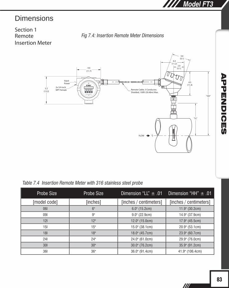
F1 F2 F3 F4
FLOW LC
3.6(9.1)
4.4(11.2)
2.0(5.1)
4.5(11.4)
“HH”
Remote Cable, 5 Conductor,Shielded, 100ft (30.48m) Max.
“LL”
5.2(13.2)
4.6(11.7)
InputPower
2x 3/4 inch NPT Female
83
Dimensions
Section 1
Model FT3D
IMEN
SIO
NS
83
Model FT3D
IMEN
SIO
NS
399 Reservation Road, Marina, CA 93933 Ph: 831.384.4300 Fax: 831.384.4312
Remote Insertion Meter
Fig 7.4: Insertion Remote Meter Dimensions
Table 7.4 Insertion Remote Meter with 316 stainless steel probe
Probe Size Probe Size Dimension “LL” ± .01 Dimension “HH” ± .01
[model code] [inches] [inches / centimeters] [inches / centimeters]06I 6" 6.0" (15.2cm) 11.9" (30.2cm)
09I 9" 9.0" (22.9cm) 14.9" (37.9cm)
12I 12" 12.0" (15.0cm) 17.9" (45.5cm)
15I 15" 15.0" (38.1cm) 20.9" (53.1cm)
18I 18" 18.0" (45.7cm) 23.9" (60.7cm)
24I 24" 24.0" (61.0cm) 29.9" (76.0cm)
30I 30" 30.0" (76.2cm) 35.9" (91.2cm)
36I 36" 36.0" (91.4cm) 41.9" (106.4cm)
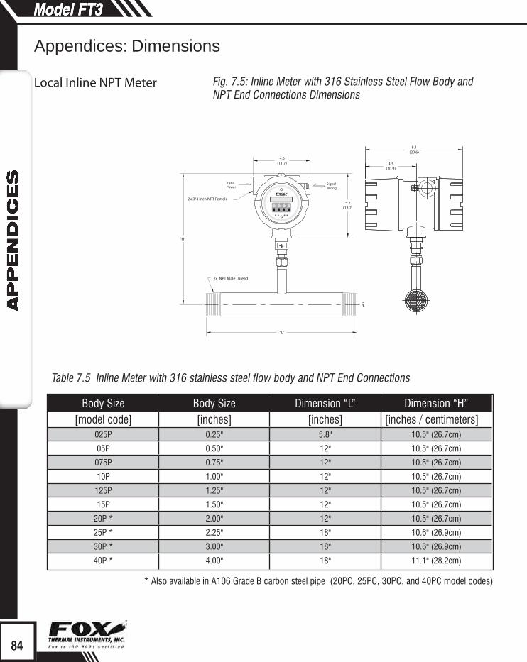
2x 3/4 inch NPT Female
“H”
“L”
LC
2x NPT Male Thread
4.6(11.7)
5.2(13.2)
F1 F2 F3 F4
8.1(20.6)
4.3(10.9)
SignalWiring
InputPower
84
Model FT3D
IMEN
SIO
NS
www.foxthermalinstruments.com
Model FT3Model FT3
Local Inline NPT Meter
Appendices: Dimensions
Table 7.5 Inline Meter with 316 stainless steel flow body and NPT End Connections
Remote Inline NPTFig. 7.5: Inline Meter with 316 Stainless Steel Flow Body and NPT End Connections Dimensions
Body Size Body Size Dimension “L” Dimension “H”[model code] [inches] [inches] [inches / centimeters]
025P 0.25" 5.8" 10.5" (26.7cm)
05P 0.50" 12" 10.5" (26.7cm)
075P 0.75" 12" 10.5" (26.7cm)
10P 1.00" 12" 10.5" (26.7cm)
125P 1.25" 12" 10.5" (26.7cm)
15P 1.50" 12" 10.5" (26.7cm)
20P * 2.00" 12" 10.5" (26.7cm)
25P * 2.25" 18" 10.6" (26.9cm)
30P * 3.00" 18" 10.6" (26.9cm)
40P * 4.00" 18" 11.1" (28.2cm)
* Also available in A106 Grade B carbon steel pipe (20PC, 25PC, 30PC, and 40PC model codes)

3.6(9.1)
4.4(11.2)
2.0(5.1)
2.0(5.1)
“HH”
Remote Cable, 5 Conductor,Shielded, 100FT Max.
“L”
LC
2x NPT Male Thread
4.6(11.7)
5.2(13.2)
F1 F2 F3 F4
InputPower
85
Model FT3D
IMEN
SIO
NS
399 Reservation Road, Marina, CA 93933 Ph: 831.384.4300 Fax: 831.384.4312
Appendices: Dimensions
Remote Inline NPT
Table 7.6 Inline Remote Meter with 316 stainless steel flow body and NPT End Connections
Fig. 7.6: Inline Remote Meter with 316 Stainless Steel Flow Body and NPT End Connections Dimensions
Body Size Body Size Dimension “L” Dimension “HH”[model code] [inches] [inches] [inches / centimeters]
05P 0.50" 12" 10.5" (26.7cm)
075P 0.75" 12" 10.5" (26.7cm)
10P 1.00" 12" 10.5" (26.7cm)
125P 1.25" 12" 10.5" (26.7cm)
15P 1.50" 12" 10.5" (26.7cm)
20P * 2.00" 12" 10.5" (26.7cm)
25P * 2.25" 18" 10.6" (26.9cm)
30P * 3.00" 18" 10.6" (26.9cm)
40P * 4.00" 18" 11.1" (28.2cm)
* Also available in A106 Grade B carbon steel pipe (20PC, 25PC, 30PC, and 40PC model codes)

2x 3/4 inch NPT Female
“H”
“L”
LC
4.6(11.7)
5.2(13.2)
2X Flange, Raised Face, ANSI B16.5, 316 SST
8.1(20.6)
4.3(10.9)
F1 F2 F3 F4
86
Model FT3D
IMEN
SIO
NS
www.foxthermalinstruments.com
Local Inline Flange Meter
Appendices: Dimensions
Table 7.7 Inline Meter with 316 stainless steel flow body and 150# RF Flange End Connections
Remote InlineFlange Meter
Fig. 7.7: Inline Meter with 316 Stainless Steel Flow Body and 150# RF Flange End Connections Dimensions
Body Size Body Size Dimension “L” Dimension “H”[model code] [inches] [inches] [inches / centimeters]
05F 0.50" 12" 10.5" (26.7cm)
075F 0.75" 12" 10.5" (26.7cm)
10F 1.00" 12" 10.5" (26.7cm)
125F 1.25" 12" 10.5" (26.7cm)
15F 1.50" 12" 10.5" (26.7cm)
20F * 2.00" 12" 10.5" (26.7cm)
25F * 2.25" 18" 10.6" (26.9cm)
30F * 3.00" 18" 10.6" (26.9cm)
40F * 4.00" 18" 11.1" (28.2cm)
60F 6.00" 24" 12.2" (31.0cm)
* Also available in A106 Grade B carbon steel pipe with A105 flanges (20FC, 25FC, 30FC, and 40FC model codes)

2X 3/4 " NPT,Female
3.6(9.1)
4.4(11.2)
2.0(5.1)
4.5(11.4)
“HH”
“L”
CL
Remote Cable, 5 Conductor,Shielded, 100FT Max.
4.6(11.7)
F1 F2 F3 F45.2(13.2)
87
Appendices: Dimensions
Remote InlineFlange Meter
Table 7.8 Inline Remote Meter with stainless steel flow body and 150# RF Flange End Connections
Model FT3D
IMEN
SIO
NS
399 Reservation Road, Marina, CA 93933 Ph: 831.384.4300 Fax: 831.384.4312
Fig. 7.8: Inline Remote Meter with Stainless Steel Flow Body and 150# RF Flange End Connections Dimensions
Body Size Body Size Dimension “L” Dimension “HH”[model code] [inches] [inches] [inches / centimeters]
05F 0.50" 12" 10.5" (26.7cm)
075F 0.75" 12" 10.5" (26.7cm)
10F 1.00" 12" 10.5" (26.7cm)
125F 1.25" 12" 10.5" (26.7cm)
15F 1.50" 12" 10.5" (26.7cm)
20F * 2.00" 12" 10.5" (26.7cm)
25F * 2.25" 18" 10.6" (26.9cm)
30F * 3.00" 18" 10.6" (26.9cm)
40F * 4.00" 18" 11.1" (28.2cm)
60F 6.00" 24" 12.2" (31.0cm)
* Also available in A106 Grade B carbon steel pipe with A105 flanges (20FC, 25FC, 30FC, and 40FC model codes)

F1 F2 F3 F4
F1 F2 F3 F4
F1 F2 F3 F4
: Installation Variations (moisture)
88
AppendicesSection 1
Model FT3APPEN
DIC
ES
www.foxthermalinstruments.com
Tilt Installations Tilt Installation at 45°, CW
Tilt InstallationsThese variations on installations help prevent moisture and condensation from forming on the sensor and disrupting accurate flow measurement. Fox recommends 180° installation, if possible.
Tilt Installation at 180°
Tilt Installation at 90°, CCW
Tilt Installation at 90°, CW

F1F2
F3
F4
: Installation Variations (limited space)
89
AppendicesSection 1
Model FT3APPEN
DIC
ES
399 Reservation Road, Marina, CA 93933 Ph: 831.384.4300 Fax: 831.384.4312
Tilt Installation at 45°, CW
Tilt Installation at 45°When restricted physical installation space exists, the FT3 can also be installed at a 45° angle. Please note that the display's orientation will remain aligned with the top of the meter.
Note: Displays are rotatable only in 90° angle increments.
For more information about display configurations, visit www.foxthermalinstruments.com to view other display configurations.

Warranty(a) FOX warrants that the products furnished under this Agreement will be free from defects in material and workmanship for a period of one year from the date of shipment. The customer shall provide notice of any defect to FOX, within one week after the Customer’s discovery of such defect. The sole obligation and liability of FOX, under this warranty shall be repair or replace, at its option, without cost to the Customer, the defective product or part.
(b) Upon request by FOX, the product or part claimed to be defective shall immediately be returned at the Customer’s expense to FOX. Replaced or repaired products or parts will be shipped to the Customer at the expense of FOX. FOX shall have the right of final determination as to the existence and cause of defect.
(c) There shall be no warranty or liability for any products or parts that have been subject to misuse, accident, negligence, failure of electric power or modifications by the Customer without the written approval of FOX. Final determination of warranty eligibility shall be made by FOX. If a warranty claim is considered invalid for any reason, the Customer will be charged for services performed and expenses incurred by FOX, in handling and shipping the returned unit.
(d) The liability of FOX shall be limited to replacing or repairing, at its option, any defective parts which are returned. Labor and related expenses incurred to install replacement parts are not covered by this warranty.(e) As to replacement parts supplied or repairs made during the original warranty period, the warranty period for the replacement or repaired part shall terminate with the termination of the warranty period of the original product or part.
(f) The use of these products is under exclusive control of the purchaser and FOX specifically denies any responsibility for the calibration of units and/or accuracy of work performed or the safety of the system in which FOX products is used. EXTERNAL SAFETY DEVICES MUST BE USED WITH THIS EQUIPMENT.
90
Appendices: Warranty
Model FT3APPEN
DIC
ES
Warranty Warranty

(g) No warranty is made with respect to custom equipment or products produced to Buyer’s specifications except as specifically stated in writing by FOX and contained in the agreement.
(h) THE FOREGOING WARRANTY CONSTITUTES THE SOLE LIABILITY OF FOX, AND THE CUSTOMER’S SOLE REMEDY WITH RESPECT TO THE PRODUCTS AND IS IN LIEU OF ALL OTHER WARRANTIES, INCLUDING ANY WARRANTY OF MERCHANTABILITY OR FITNESS FOR A PARTICULAR PURPOSE, LIABILITIES, AND REMEDIES. EXCEPT AS THUS PROVIDED, FOX, DISCLAIMS ALL WARRANTIES, EXPRESS OR IMPLIED, INCLUDING ANY WARRANTY OF MERCHANTABILITY OR FITNESS FOR A PARTICULAR PURPOSE.
91
Appendices: Warranty
Model FT3APPEN
DIC
ES
Warranty

i
Returning Your MeterThe Fox Thermal Instruments, Inc. Customer Service Department (PH: 831- 384-4300 or FAX: 831-337-5787) can help you through the process of returning a meter for service.
If it becomes necessary to return a Fox flow meter for service or recalibration, please follow these steps:
1. A Return Material Authorization (RMA) Number must be obtained from the Fox Customer Service Department prior to returning any Fox meter(s).
2. Please have your meter’s serial number(s) available.3. Read and complete the Fox RMA Customer Information Form. Be sure to
initial the decontamination statement as well as provide complete return shipping instructions (we cannot deliver to post office boxes).
4. The entire flow meter must be returned, including all electronics (unless specifically instructed to do otherwise). ALL serial numbers must match their corresponding meters. This is especially necessary when returning remote and/or flow body models.
5. Clean and decontaminate all wetted parts before returning to Fox.6. Ship the meter to the following address:
Fox Thermal Instruments, Inc.399 Reservation RoadMarina, CA 93933Attn: Service Dept.[RMA Number]
Note: Be sure to review all of the information on the Customer Information Form before sending your meter to the Fox Customer Service Department. The Fox Shipping/Receiving Department cannot accept meters that have not been prepared appropriately.
92
DisclaimerSection 1
Model FT3D
ISC
LAIM
ER
www.foxthermalinstruments.com
Appendices: Returning Your Meter
What to Expect During Servicing
Returning Your Meter

What to expect while your meter is being servicedDepending on the type of service required when returning your Fox meter, there are varying turnover times for servicing a meter. The average time needed to service the meter is 7-10 days (not including shipping or peak production times).
If you have already shipped your meter to Fox for servicing and would like to check the status of your meter, please fill out our online Service Order Status form located at www.foxthermalinstruments.com and you will hear from a Customer Service Rep within 1 business day of your requested update.
Rush recalibration service is available for a fee. Restrictions apply.
93
Disclaimer
Section 1
Model FT3D
ISC
LAIM
ER
399 Reservation Road, Marina, CA 93933 Ph: 831.384.4300 Fax: 831.384.4312
What to Expect During Servicing

Aa
94
Definitions
Glossary of Terms and Definitions
Model FT3D
EFIN
ITIO
NS
Glossary of Terms and Definitions
AC Alternating CurrentAWG American Wire GaugeBara Bar absoluteCTC ContactCAL CalibrationCHG ChangeCOM CommunicationCSV Current Sense VoltageDC Direct CurrentDN DownDSP DisplayELP Elapsed timeFeq FrequencyFt^2 Square FeetI/O Input/OutputINP InputIR Infrared (IR Buttons = optical switches)LB PoundLB/D Pound per DayLB/H Pound per HourLB/M Pound per MinuteLB/S Pound per SecondLCD Liquid Crystal DisplayKG KilogramKG/H Kilogram per HourKG/M Kilogram per Minute KG/S Kilogram per Second M^2 Square MetermmHG Pressure in millimeters of mercuryMMSCFD Million Standard Cubic Feet per DayMXFLO Maximum FlowNEMA National Electrical Manufactures AssociationNIST National Institute of Standards and TechnologyNLP Normal LiterNLPH Normal Liter per HourNLPM Normal Liter per MinuteNM3 Normal cubic Meter

Aa
95
Definitions
Glossary of Terms and Definitions
Model FT3D
EFIN
ITIO
NS
NM3/H Normal cubic Meter per HourNM3/M Normal cubic Meter per MinuteNPT National Pipe ThreadPDA Personal hand held computerUNT UnitU/P Unit per PulsePC Personal ComputerP/U Pulse per UnitPIP A^2 Pipe AreaPLC Programmable Logic ControllerPRM ParametersPRS PressurePSIA Pounds per Square Inch AbsolutePt PointPSW PasswordSIM SimulationSCF Standard Cubic Feet SCFM Standard Cubic Feet per MinuteSCFH Standard Cubic Feet per HourSCFD Standard Cubic Feet per DaySPC Special ControlSTP Standard Temperature and PressureTMP TemperatureTSI Internal VariableTSV Internal Variable420 4 to 20mA output
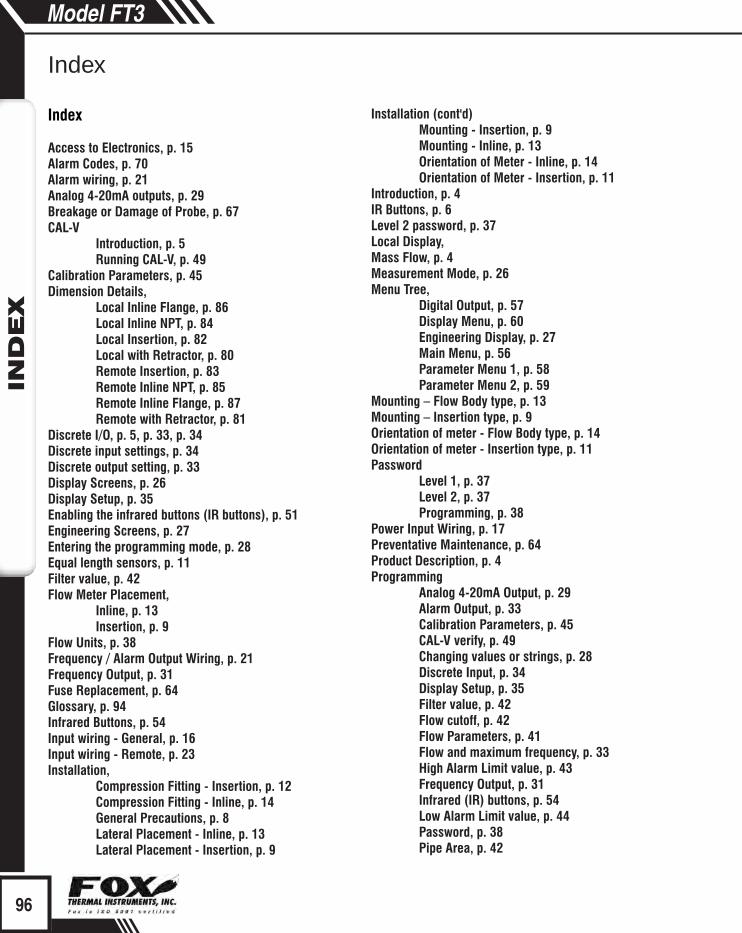
96
Index
Model FT3IN
DEX
Index
Access to Electronics, p. 15Alarm Codes, p. 70Alarm wiring, p. 21Analog 4-20mA outputs, p. 29Breakage or Damage of Probe, p. 67CAL-V Introduction, p. 5 Running CAL-V, p. 49Calibration Parameters, p. 45Dimension Details, Local Inline Flange, p. 86 Local Inline NPT, p. 84 Local Insertion, p. 82 Local with Retractor, p. 80 Remote Insertion, p. 83 Remote Inline NPT, p. 85 Remote Inline Flange, p. 87 Remote with Retractor, p. 81Discrete I/O, p. 5, p. 33, p. 34Discrete input settings, p. 34Discrete output setting, p. 33Display Screens, p. 26Display Setup, p. 35Enabling the infrared buttons (IR buttons), p. 51Engineering Screens, p. 27Entering the programming mode, p. 28Equal length sensors, p. 11Filter value, p. 42Flow Meter Placement, Inline, p. 13 Insertion, p. 9Flow Units, p. 38Frequency / Alarm Output Wiring, p. 21Frequency Output, p. 31Fuse Replacement, p. 64Glossary, p. 94Infrared Buttons, p. 54Input wiring - General, p. 16Input wiring - Remote, p. 23Installation, Compression Fitting - Insertion, p. 12 Compression Fitting - Inline, p. 14 General Precautions, p. 8 Lateral Placement - Inline, p. 13 Lateral Placement - Insertion, p. 9
Installation (cont'd) Mounting - Insertion, p. 9 Mounting - Inline, p. 13 Orientation of Meter - Inline, p. 14 Orientation of Meter - Insertion, p. 11 Introduction, p. 4IR Buttons, p. 6Level 2 password, p. 37Local Display, Mass Flow, p. 4Measurement Mode, p. 26Menu Tree, Digital Output, p. 57 Display Menu, p. 60 Engineering Display, p. 27 Main Menu, p. 56 Parameter Menu 1, p. 58 Parameter Menu 2, p. 59Mounting – Flow Body type, p. 13Mounting – Insertion type, p. 9Orientation of meter - Flow Body type, p. 14Orientation of meter - Insertion type, p. 11Password Level 1, p. 37 Level 2, p. 37 Programming, p. 38Power Input Wiring, p. 17Preventative Maintenance, p. 64Product Description, p. 4Programming Analog 4-20mA Output, p. 29 Alarm Output, p. 33 Calibration Parameters, p. 45 CAL-V verify, p. 49 Changing values or strings, p. 28 Discrete Input, p. 34 Display Setup, p. 35 Filter value, p. 42 Flow cutoff, p. 42 Flow Parameters, p. 41 Flow and maximum frequency, p. 33 High Alarm Limit value, p. 43 Frequency Output, p. 31 Infrared (IR) buttons, p. 54 Low Alarm Limit value, p. 44 Password, p. 38 Pipe Area, p. 42
97
Index
Model FT3IN
DEX
Programming (cont'd) Programming Mode, p. 28 Pulse-per-unit, p. 32 Reset Total & Elapsed Time, p. 46 Restore Database, p. 46 Reset CRC, p. 47 Selecting from a list, p. 28 Serial Communication, p. 35 Simulation, p. 47 Unit-per-pulse, p. 33 Unit settings, p. 38 Using the Local Display, p. 28Remote Wiring Installation, p. 23Replacements Fuses, p. 64 Reset Total and Elapsed Time, p. 46Restore Database, p. 46Return Procedure, p. 92Scope, p. 8Sensor Cleaning, p. 64Sensor Orientation, Inline, Insertion, Signal wiring, p. 19Simulation Mode, p. 47Theory of Operation, p. 4To program the display, p. 36Totalizer Rollover, p. 46Troubleshooting, p. 67 Alarm Codes, p. 70 General, p. 67 Installation Problems, p. 68Unequal length sensors, p. 12USB Interface, p. 25Warranty, p. 90Wiring Alarms, p. 21 Frequency/Alarm Outputs, p. 21 Grounding, p. 15 Input - Remote, p. 23 Instructions, p. 15 Power Input, p. 17 Precautions, p. 15 Remote meters, p. 23 Sensor, p. 23Zero CAL-CHECK Introduction, p. 5 Running Zero CAL-CHECK, p. 51

iCaution - (refer to accompanying documents): Please follow the specified instructions and general safety practices.
Wiring
Definition of Terms
Troubleshooting Tips
Information
Aa
Indicates compliance with the WEEE Directive. Please dispose of the product in accordance with local regulations and conventions.
Indicates compliance with the applicable European Union Directives for Safety LVD (Low Voltage Directive 2006/95/EC), EMC (Electromagnetic Compatibility Directive 2004/108/EC), and PED (Pressure Equipment Directive 97/23/EC).
Enclosure Protection Classification per IEC 60529: Protected against the ingress of dust and Immersion.
IP67