forward view info
TRANSCRIPT
COUNTRY :E.E.C. © ,17(55(*6#/WG#4<<<ORIGINAL :O.J. L 267 of October 19, 1977
TITLE: Motor Vehicles ISSUE: 1 77/649/EECDrivers Forward Visibility Nov/1991 PAGE: 1
COUNCIL DIRECTIVE
of September 27, 1977
on the approximation of the laws of the Member States relating to the fieldof vision of motor vehicle drivers
(77/649/EEC)
As amended by Directives 81/643/EEC, 88/366/EEC and 90/630/EEC
THE COUNCIL OF THE EUROPEAN COMMUNITIES,
Having regard to the Treaty establishing the European Economic Community, and in particular Article 100thereof,
Having regard to the proposal from the Commission,
Having regard to the opinion of the European Parliament (1),
Having regard to the opinion of the Economic and Social Committee (2),
Whereas the technical requirements which motor vehicles must satisfy pursuant to national laws relate, interalia, to the field of vision of the driver;
Whereas these requirements differ from one Member State to another; whereas it is therefore necessary thatall Member States adopt the same requirements, either in addition to or in place of their existing rules, inorder, in particular, to allow the EEC type-approval procedure, which was the subject of Council Directive70/156/EEC of February 6, 1970 on the approximation of the laws of the Member States relating to thetype-approval of motor vehicles and their trailers, to be introduced in respect of each type of vehicle (3);
Whereas it is desirable to draft the technical requirements so that they have the same aim as the work beingcarried out on the subject in the UN Economic Commission for Europe;
Whereas those requirements apply to motor vehicles in category M1 (the international classification of motorvehicles is given in Annex I to Directive 70/156/EEC);
Whereas the approximation of national laws relating to motor vehicles entails reciprocal recognition byMember States of the checks carried out by each of them on the basis of the common requirements,
(1) OJ No C 125, 8.6.1976, p. 49.(2) OJ No C 197, 23.8.1976, p. 10.(3) OJ No L 42, 23.2.1970, p. 1.
COUNTRY :E.E.C. © ,17(55(*6#/WG#4<<<ORIGINAL :O.J. L 267 of October 19, 1977
TITLE: Motor Vehicles ISSUE: 1 77/649/EECDrivers Forward Visibility Nov/1991 PAGE: 2
HAS ADOPTED THIS DIRECTIVE:
ARTICLE 1
For the purposes of this Directive, 'vehicle' means any motor vehicle in category M1 (defined in Annex I toDirective 70/156/EEC) intended for use on the road, having at least four wheels and a maximum designspeed exceeding 25 km/h.
ARTICLE 2
No Member State may refuse to grant EEC type-approval or national type-approval of a vehicle on groundsrelating to the driver's field of vision if it satisfies the requirements set out in Annexes I, III and IV.
ARTICLE 3
No Member State may refuse or prohibit the sale, registration, entry into service or use of any vehicle ongrounds relating to the driver's field of vision if it satisfies the requirements set out in Annexes I, III and IV.
ARTICLE 4
The Member State which has granted type-approval shall take the measures required to ensure that it isinformed of any modification of a part or characteristic referred to in section 2.2. of Annex I. The competentauthorities of that State shall determine whether it is necessary to carry out further tests on the modifiedvehicle type and to prepare a new report. If these tests show that the requirements of this Directive have notbeen complied with, the modification shall not be authorized.
ARTICLE 5
Any amendments necessary to adapt the requirements of Annexes I, III, IV, and V to technical progress shallbe adopted in accordance with the procedure laid down in Article 13 of Directive 70/156/EEC.
However, this procedure shall not apply to amendments introducing provisions relating to a field of visionother than 180° forward field of vision.
ARTICLE 6
1. Member States shall bring into force the provisions necessary in order to comply with this Directivewithin 18 months of its notification and shall forthwith inform the Commission thereof.
2. Member States shall ensure that the text of the main provisions of national law which they adopt in thefield covered by this Directive are communicated to the Commission.
COUNTRY :E.E.C. © ,17(55(*6#/WG#4<<<ORIGINAL :O.J. L 267 of October 19, 1977
TITLE: Motor Vehicles ISSUE: 1 77/649/EECDrivers Forward Visibility Nov/1991 PAGE: 3
ARTICLE 7
This Directive is addressed to the Member States.
Done at Brussels, September 27, 1977.
For the Council
The President
A. HUMBLET

COUNTRY :E.E.C. © ,17(55(*6#/WG#4<<<ORIGINAL :O.J. L 267 of October 19, 1977
TITLE: Motor Vehicles ISSUE: 2 77/649/EECDrivers Forward Visibility June/1992 PAGE: 4
LIST OF ANNEXES
Annex I: Scope, definitions, application for EEC type-approval, EEC type-approval, specifications,test procedure (1).
(Annex II)
Annex III: Procedure for determining the 'H' point and the actual seat-back angle and for verifyingthe relative positions of the R and H points and the relationship between the designseat-back angle and the actual seat-back angle (1). Figures 1 and 2.
Annex IV: Method for determining the dimensional relationships between the vehicle's primaryreference marks and the three-dimensional reference grid (1). Figures 1 to 7.
Annex V: Annex to the EEC vehicle type-approval certificate with regard to the driver's field of vision.
(1) The technical requirements of this Annex are similar to those of the relevant UN Economic Commission for Europe draft
Regulation; in particular the breakdown into sections is the same. Where a section of the draft Regulation has no counterpart inthe Annexes to this Directive, the number is given in brackets for the record.

COUNTRY :E.E.C. © ,17(55(*6#/WG#4<<<ORIGINAL :O.J. L 267 of October 19, 1977
TITLE: Motor Vehicles ISSUE: 1 77/649/EECDrivers Forward Visibility Nov/1991 PAGE: 5
ANNEX I
SCOPE, DEFINITIONS, APPLICATION FOR EEC TYPE-APPROVAL,EEC TYPE-APPROVAL, SPECIFICATIONS, TEST PROCEDURE
1. SCOPE
1.1. This Directive applies to the 180° forward field of vision of the drivers of vehicles in category M1.
1.1.1. Its purpose is to ensure an adequate field of vision when the windscreen and other glazedsurfaces are dry and clean.
1.2. The requirements of this Directive are so worded as to apply to category M1 vehicles in whichthe driver is on the left. In category M1 vehicles in which the driver is on the right theserequirements shall be applied by inverting the criteria where appropriate.
2. DEFINITIONS
(2.1.)
2.2. Vehicle type with regard to the field of vision
'Vehicle type with regard to the field of vision' means vehicles which do not differ in suchessential respects as:
2.2.1. the external and internal forms and arrangements within the area specified in section 1 whichmay affect visibility; and
2.2.2. the shape and dimensions of the windscreen and its mounting.
2.3. Three-dimensional reference grid
'Three-dimensional reference grid' means a reference system which consists of a verticallongitudinal plane X-Z, a horizontal plane X-Y and a vertical transverse plane Y-Z (see Annex IV,Appendix, Figure 5); the grid is used to determine the dimensional relationships between theposition of design points on drawings and their position on the actual vehicle. The procedurefor situating the vehicle relative to the grid is specified in Annex IV; all coordinates referred toground zero shall be based on a vehicle in running order (as defined in section 2.6 of Annex Ito Directive 70/156/EEC) plus one front-seat passenger, the mass of the passenger being75 kg ± 1 %.
2.3.1. Vehicles fitted with suspension enabling their ground clearance to be adjusted shall be testedunder the normal conditions of use specified by the vehicle manufacturer.
COUNTRY :E.E.C. © ,17(55(*6#/WG#4<<<ORIGINAL :O.J. L 267 of October 19, 1977
TITLE: Motor Vehicles ISSUE: 1 77/649/EECDrivers Forward Visibility Nov/1991 PAGE: 6
2.4. Primary reference marks
'Primary reference marks' means holes, surfaces, marks and identification signs on the vehiclebody. The type of reference mark used and the position of each mark relative to the X, Y andZ coordinates of the three-dimensional reference grid and to a design ground plane shall bespecified by the vehicle manufacturer. These marks may be the control points used forbody-assembly purposes;
2.5. Seat-back angle
(See Annex III, section 1.3)
2.6. Actual seat-back angle
(See Annex III, section 1.4)
2.7. Design seat-back angle
(See Annex III, section 1.5)
2.8. V points
'V points' means points whose position in the passenger compartment is determined as afunction of vertical longitudinal planes passing through the centres of the outermost designatedseating positions on the front seat and in relation to the R point and the design angle of theseat-back, which points are used for verifying compliance with the field of vision requirements;
2.9. R point or seating reference point
(See Annex III, section 1.2)
2.10. H point
(See Annex III, section 1.1)
2.11. Windscreen datum points
'Windscreen datum points' means points situated at the intersection with the windscreen of linesradiating forward from the V points to the outer surface of the windscreen.
2.12. Transparent area
'Transparent area' means that area of a vehicle windscreen or other glazed surface whose lighttransmittance measured at right angles to the surface, is not less than 70 %.
2.13. P points
'P points' means the points about which the driver's head rotates when he views objects on ahorizontal plane at eye level.

COUNTRY :E.E.C. © ,17(55(*6#/WG#4<<<ORIGINAL :O.J. L 267 of October 19, 1977
TITLE: Motor Vehicles ISSUE: 1 77/649/EECDrivers Forward Visibility Nov/1991 PAGE: 7
2.14. E points
'E points' means points representing the centres of the driver's eyes and used to assess theextent to which A pillars obscure the field of vision.
2.15. A pillar
'A pillar' means any roof support forward of the vertical transverse plane located 68 mm in frontof the V points and includes non-transparent items, such as windscreen mouldings and doorframes, attached or contiguous to such a support.
2.16. Horizontal seat-adjustment range
'Horizontal seat-adjustment range' means the range of normal driving positions designated bythe vehicle manufacturer for the adjustment of the driver's seat in the direction of the X axis(see 2.3).
2.17. Extended seat adjustment range
'Extended seat adjustment range' means the range designated by the vehicle manufacturer forthe adjustment of the seat in the direction of the X axis (see 2.3) beyond the range of normaldriving positions specified in 2.16 and used for converting seats into beds or facilitating entryinto the vehicle.
(2.18.)
3. APPLICATION FOR EEC TYPE-APPROVAL
3.1. The application for EEC type-approval of a vehicle type with regard to the driver's field of visionshall be submitted by the vehicle manufacturer or by his authorized representative.
3.2. It shall be accompanied by the following documents in triplicate, and by the following particulars;
3.2.1. a description of the vehicle with regard to the items mentioned in 2.2, together with dimensionaldrawings and either a photograph or an exploded view of the passenger compartment. Thenumbers and/or symbols identifying the vehicle type shall be specified; and
3.2.2. particulars of the primary reference marks in sufficient detail to enable them to be readilyidentified and the position of each in relation to the others and to the R point to be verified.
3.3. A vehicle representative of the vehicle type to be approved shall be submitted to the technicalservice conducting the approval tests.
COUNTRY :E.E.C. © ,17(55(*6#/WG#4<<<ORIGINAL :O.J. L 267 of October 19, 1977
TITLE: Motor Vehicles ISSUE: 1 77/649/EECDrivers Forward Visibility Nov/1991 PAGE: 8
4. EEC TYPE-APPROVAL
(4.1.)
(4.2.)
4.3. A certificate conforming to the model shown in Annex V shall be attached to the EECtype-approval certificate.
(4.4.) - (4.4.1) - (4.4.2)
(4.5.)
(4.6.)
(4.7.)
(4.8.)
5. SPECIFICATIONS
5.1. Driver's field of vision
5.1.1. The transparent area of the windscreen must include at least the windscreen datum points;these are:
5.1.1.1. a horizontal datum point forward of V1 and 17° to the left (see Annex IV, Appendix, Figure 1);
5.1.1.2. an upper vertical datum point forward of V1 and 7° above the horizontal. However, this angleshall be reduced to 5° until September 30, 1981.
5.1.1.3. a lower vertical datum point forward of V2 and 5° below the horizontal;
5.1.1.4. to verify compliance with the forward-vision requirement on the opposite half of the windscreen,three additional datum points, symmetrical to the points defined in 5.1.1.1 to 5.1.1.3 in relationto the median longitudinal plane of the vehicle, are obtained.
5.1.2. The angle of obstruction of each "A" pillar, as described in point 5.1.2.1, shall not exceed 6° (SeeAnnex IV, Appendix, Figure 3).
The angle of obstruction of each "A" pillar on the passenger side, as described in point 5.1.2.1.2,need not be determined if the two pillars are located symmetrically in relation to the medianlongitudinal vertical plane of the vehicle.

COUNTRY :E.E.C. © ,17(55(*6#/WG#4<<<ORIGINAL :O.J. L 267 of October 19, 1977
TITLE: Motor Vehicles ISSUE: 1 77/649/EECDrivers Forward Visibility Nov/1991 PAGE: 9
5.1.2.1. The angle of obstruction of each "A" pillar shall be measured by superimposing in a plane thefollowing two horizontal sections:
Section 1: Starting from the Pm point situated at the location defined in point 5.3.1.1, draw aplane forming an angle of 2° upwards in relation to the horizontal plane passingforward through Pm. Determine the horizontal section of the "A" pillar starting fromthe foremost point of the intersection of the "A" pillar and the inclined plane(See Annex IV, Appendix, Figure 2).
Section 2: Repeat the same procedure, taking a plane at an angle of 5° downwards in relationto the horizontal plane passing forward through Pm. (See Annex IV, Appendix,Figure 2).
5.1.2.1.1. The angle of obstruction of the "A" pillar on the driver's side is the angle formed on the planeview by a parallel, starting from E2, to the tangent joining E1 with the outer edge of Section S2
and the tangent joining E2 with the inner edge of section S1 (See Annex IV, Appendix, Figure 3).
5.1.2.1.2. The angle of obstruction of the "A" pillar on the passenger side is the angle formed on the planeview by the tangent joining E3, to the inner edge of Section S1 and a parallel, starting from E3,to the tangent joining E4 to the outer edge of Section S2 (See Annex IV, Appendix, Figure 3).
5.1.2.2. No vehicle shall have more than two "A" pillars.
5.1.3. Other than the obstructions created by the "A" pillars, the fixed or movable vent or side windowdivision bars, outside radio aerials, rear-view mirrors and windscreen wipers, there should beno obstruction in the driver's 180° forward direct field of vision below a horizontal plane passingthrough V1, and above three planes through V2, one being perpendicular to the plane X-Z anddeclining forward 4° below the horizontal and the other two being perpendicular to the plane Y-Zand declining 4° below the horizontal (See Annex IV, Figure 4).
The following are not considered to be obstructions to the field of vision:
— embedded or printed "radio aerial" conductors no wider than the following:
— embedded conductors: 0.5 mm,
— printed conductors: 1.0 mm.
These "radio aerial" conductors shall not cross zone A, as defined in Directive 78/318/EECrelating to wiper and washer systems of motor vehicles (1). However, three "radio aerial"conductors may, cross zone A if their width does not exceed 0.5 mm.
(1) OJ No L 81, 28.3.1978, p. 49.

COUNTRY :E.E.C. © ,17(55(*6#/WG#4<<<ORIGINAL :O.J. L 267 of October 19, 1977
TITLE: Motor Vehicles ISSUE: 2 77/649/EECDrivers Forward Visibility June/1992 PAGE: 10
— within zone A "defrosting/demisting" conductors, normally in "zigzag" or sinusoidal formhaving the following dimensions:
— maximum visible width: 0,030 mm,— maximum conductor density:— if the conductors are vertical: 8/cm,— if the conductors are horizontal: 5/cm,
5.1.3.1. An obstruction created by the steering-wheel rim and the instrument panel inside the steeringwheel will be tolerated if a plane through V2, perpendicular to the plane X-Z and tangential to thehighest part of the steering-wheel rim, is declined at least 1° below the horizontal.
5.2. Position of the V points
5.2.1. The positions of the V points in relation to the R point, as indicated by XYZ coordinates from thethree-dimensional reference grid, are as shown in Tables I and IV.
5.2.1.1. Table I indicates the basic coordinates for a design seat-back angle of 25°. The positivedirection for the coordinates is indicated in Annex IV, Appendix, Figure 1.
TABLE I
V-point x y z
V1 68 mm — 5 mm 665 mm
V2 68 mm — 5 mm 589 mm
5.3. Positions of the P points
5.3.1. The positions of the P points in relation to the R point, as indicated by the XYZ coordinates fromthe three-dimensional reference grid, are as shown by Tables II, III and IV.
5.3.1.1. Table II sets out the basic coordinates for a design seat-back angle of 25°. The positivedirection of the coordinates is set out in Annex IV, Appendix, Figure 1.
The Pm point is the point of intersection between the straight line P1, P2 and the longitudinalvertical plane passing through the R point.
TABLE II
Point P X Y Z
P1 35 mm — 20 mm 627 mm
P2 63 mm 47 mm 627 mm
Pm 43,36 mm 0 mm 627 mm
COUNTRY :E.E.C. © ,17(55(*6#/WG#4<<<ORIGINAL :O.J. L 267 of October 19, 1977
TITLE: Motor Vehicles ISSUE: 1 77/649/EECDrivers Forward Visibility Nov/1991 PAGE: 11
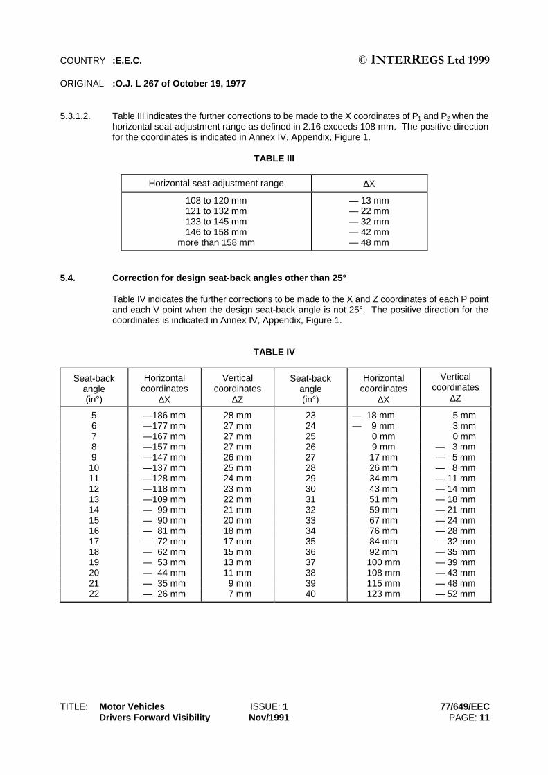
5.3.1.2. Table III indicates the further corrections to be made to the X coordinates of P1 and P2 when thehorizontal seat-adjustment range as defined in 2.16 exceeds 108 mm. The positive directionfor the coordinates is indicated in Annex IV, Appendix, Figure 1.
TABLE III
Horizontal seat-adjustment range ∆X
108 to 120 mm121 to 132 mm133 to 145 mm146 to 158 mm
more than 158 mm
— 13 mm— 22 mm— 32 mm— 42 mm— 48 mm
5.4. Correction for design seat-back angles other than 25°
Table IV indicates the further corrections to be made to the X and Z coordinates of each P pointand each V point when the design seat-back angle is not 25°. The positive direction for thecoordinates is indicated in Annex IV, Appendix, Figure 1.
TABLE IV
Seat-backangle(in°)
Horizontalcoordinates
∆X
Verticalcoordinates
∆Z
Seat-backangle(in°)
Horizontalcoordinates
∆X
Verticalcoordinates
∆Z
5 —186 mm 28 mm 23 — 18 mm 5 mm6 —177 mm 27 mm 24 — 9 mm 3 mm7 —167 mm 27 mm 25 0 mm 0 mm8 —157 mm 27 mm 26 9 mm — 3 mm9 —147 mm 26 mm 27 17 mm — 5 mm10 —137 mm 25 mm 28 26 mm — 8 mm11 —128 mm 24 mm 29 34 mm — 11 mm12 —118 mm 23 mm 30 43 mm — 14 mm13 —109 mm 22 mm 31 51 mm — 18 mm14 — 99 mm 21 mm 32 59 mm — 21 mm15 — 90 mm 20 mm 33 67 mm — 24 mm16 — 81 mm 18 mm 34 76 mm — 28 mm17 — 72 mm 17 mm 35 84 mm — 32 mm18 — 62 mm 15 mm 36 92 mm — 35 mm19 — 53 mm 13 mm 37 100 mm — 39 mm20 — 44 mm 11 mm 38 108 mm — 43 mm21 — 35 mm 9 mm 39 115 mm — 48 mm22 — 26 mm 7 mm 40 123 mm — 52 mm
COUNTRY :E.E.C. © ,17(55(*6#/WG#4<<<ORIGINAL :O.J. L 267 of October 19, 1977
TITLE: Motor Vehicles ISSUE: 2 77/649/EECDrivers Forward Visibility June/1992 PAGE: 12
5.5. Positions of the E points
5.5.1. E1 and E2 are each 104 mm from P1.
E2 is 65 mm from E1 (see Annex IV, Appendix, Figure 4).
5.5.2. The straight line joining E1 and E2 is rotated about P1 until the tangent joining E1 to the outeredge of Section 2 of the A-pillar on the driver's side is normal to the straight line E1 - E2 (SeeAnnex IV, Appendix, Figure 3).
5.5.2.1.Deleted
5.5.2.2.
5.5.3. E3 and E4 are each 104 mm from P2. E3 is 65 mm from E4. (See Annex IV, Appendix, Figure 4).
5.5.4. The straight line E3 - E4 is rotated about P2 until the tangent joining E4 to the outer edge ofSection 2 of the A-pillar on the passenger's side is normal to the straight line E3 - E4 (See AnnexIV, Appendix, Figure 3).
6. TEST PROCEDURE
6.1. Driver's field of vision
6.1.1. The dimensional relationships between the vehicle's primary reference marks and thethree-dimensional reference grid shall be determined by the procedure prescribed in Annex IV.
6.1.2. The position of the points V1 and V2 are determined in relation to the R point as indicated by XYZcoordinates from the three-dimensional reference grid and are shown in Table I under 5.2.1.1and Table IV under 5.4. The windscreen datum points shall then be found from the correctedV points as prescribed in 5.1.1.
6.1.3. The relationship between the P points, the R point, and the centre-line of the driver's seatingposition, as indicated by XYZ coordinates from the three-dimensional reference grid, shall bedetermined from Tables II and III in 5.3. The correction for design seat-back angles other than25° is shown in Table IV under 5.4.
6.1.4. The angle of obstruction (See 5.1.2) shall be measured in the inclined planes as indicated inAnnex IV, Appendix, Figure 2. The relationship between P1 and P2, which are connected to E1
and E2 and E3 and E4 respectively, is shown in Annex IV, Appendix, Figure 5.
6.1.4.1. Straight line E1 - E2 shall be set as described in 5.5.2. The angle of obstruction of the A-pillaron the driver's side shall then be measured as specified in point 5.1.2.1.1.
6.1.4.2. Straight line E3 - E4 shall be set as described in 5.5.4. The angle of obstruction of the A-pillaron the passenger side shall then be measured as specified in point 5.1.2.1.2.

COUNTRY :E.E.C. © ,17(55(*6#/WG#4<<<ORIGINAL :O.J. L 267 of October 19, 1977
TITLE: Motor Vehicles ISSUE: 1 77/649/EECDrivers Forward Visibility Nov/1991 PAGE: 13
6.1.5. The manufacturer may measure the angle of obstruction either on the vehicle or in the drawings.In case of doubt the technical services may require the tests to be carried out on the vehicle.
(7.)
(8.)
(9.)
(10.)
(ANNEX II)

COUNTRY :E.E.C. © ,17(55(*6#/WG#4<<<ORIGINAL :O.J. L 267 of October 19, 1977
TITLE: Motor Vehicles ISSUE: 1 77/649/EECDrivers Forward Visibility Nov/1991 PAGE: 14
ANNEX III
PROCEDURE FOR DETERMINING THE "H" POINT AND THE ACTUALTORSO ANGLE FOR SEATING POSITIONS IN MOTOR VEHICLES
1. PURPOSE
The procedure described in this Annex is used to establish the "H" point location and the actualtorso angle for one or several seating positions in a motor vehicle and to verify the relationshipof measured data to design specifications given by the vehicle manufacturer. (1)
2. DEFINITIONS
For the purposes of this Annex:
2.1. "Reference data" means one or several of the following characteristics of a seating position:
2.1.1. the "H" point and the "R" point and their relationship,
2.1.2. the actual torso angle and the design torso angle and their relationship.
2.2. "Three-dimensional 'H' point machine" (3 DH machine) means the device used for thedetermination of "H" points and actual torso angles. This device is described in Appendix 1 tothis Annex;
2.3. "'H' point" means the pivot centre of the torso and thigh of the 3 DH machine installed in thevehicle seat in accordance with Paragraph 4 below. The "H" point is located in the centre of thecentreline of the device which is between the "H" point sight buttons on either side of the 3 DHmachine. The "H" point corresponds theoretically to the "R" point (for tolerances see item 3.2.2below). Once determined in accordance with the procedure described in Paragraph 4, the "H"point is considered fixed in relation to the seat-cushion structure and to move with it when theseat is adjusted;
2.4. "'R' point", or "seating reference point" means a design point defined by the vehiclemanufacturer for each seating position and established with respect to the three-dimensionalreference system;
2.5. "Torso-line" means the centreline of the probe of the 3 DH machine with the probe in the fullyrearward position;
2.6. "Actual torso angle" means the angle measured between a vertical line through the "H" pointand the torso line using the back angle quadrant on the 3 DH machine. The actual torso anglecorresponds theoretically to the design torso angle (for tolerances see item 3.2.2 below);
(1) In any seating position other than front seats where the "H" point cannot be determined using the "Three-dimensional 'H' point
machine" or procedures, the "R" point indicated by the manufacturer may be taken as a reference at the discretion of thecompetent authority.

COUNTRY :E.E.C. © ,17(55(*6#/WG#4<<<ORIGINAL :O.J. L 267 of October 19, 1977
TITLE: Motor Vehicles ISSUE: 1 77/649/EECDrivers Forward Visibility Nov/1991 PAGE: 15
2.7. "Design torso angle" means the angle measured between a vertical line through the "R" pointand the torso line in a position which corresponds to the design position of the seat-backestablished by the vehicle manufacturer;
2.8. "Centreplane of occupant" (C/LO) means the median plane of the 3 DH machine positionedin each designated seating position; it is represented by the co-ordinate of the "H" point on the"Y" axis. For individual seats, the centreplane of the seat coincides with the centreplane of theoccupant. For other seats, the centreplane of the occupant is specified by the manufacturer;
2.9. "Three dimensional reference system" means a system as described in Appendix 2 to thisAnnex;
2.10. "Fiducial marks" are physical points (holes, surfaces, marks or indentations) on the vehiclebody as defined by the manufacturer;
2.11. "Vehicle measuring attitude" means the position of the vehicle as defined by the co-ordinatesof fiducial marks in the three-dimensional reference system.
3. REQUIREMENTS
3.1. Data presentation
For each seating position where reference data are required in order to demonstrate compliancewith the provisions of the present Directive, all or an appropriate selection of the following datashall be presented in the form indicated in Appendix 3 to this Annex:
3.1.1. the coordinates of the "R" point relative to the three-dimensional reference system;
3.1.2. the design torso angle;
3.1.3. all indications necessary to adjust the seat (if it is adjustable) to the measuring position set outin item 4.3 below.
3.2. Relationship between measured data and design specifications
3.2.1. The coordinates of the "H" point and the value of the actual torso angle obtained by theprocedure set out in item 4 below shall be compared, respectively, with the coordinates of the"R" point and the value of the design torso angle indicated by the vehicle manufacturer.
3.2.2. The relative positions of the "R" point and the "H" point and the relationship between the designtorso angle and the actual torso angle shall be considered satisfactory for the seating positionin question if the "H" point, as defined by its coordinates, lies within a square of 50 mm sidelength with horizontal and vertical sides whose diagonals intersect at the "R" point, and if theactual torso angle is within 5° of the design torso angle.
3.2.3. If these conditions are met, the "R" point and the design torso angle shall be used todemonstrate compliance with the provisions of this Regulation.

COUNTRY :E.E.C. © ,17(55(*6#/WG#4<<<ORIGINAL :O.J. L 267 of October 19, 1977
TITLE: Motor Vehicles ISSUE: 1 77/649/EECDrivers Forward Visibility Nov/1991 PAGE: 16
3.2.4. If the "H" point or the actual torso angle does not satisfy the requirements of item 3.2.2 above,the "H" point and the actual torso angle shall be determined twice more (three times in all). Ifthe results of two of these three operations satisfy the requirements, the conditions of item 3.2.3above shall apply.
3.2.5. If the results of at least two of the three operations described in item 3.2.4 above do not satisfythe requirements of item 3.2.2 above, or if the verification cannot take place because the vehiclemanufacturer has failed to supply information regarding the position of the "R" point or regardingthe design torso angle, the centroid of the three measured points or the average of the threemeasured angles shall be used and be regarded as applicable in all cases where the "R" pointor the design torso angle is referred to in this Directive.
4. PROCEDURE FOR "H" POINT AND ACTUAL TORSO ANGLE DETERMINATION
4.1. The vehicle shall be preconditioned at the manufacturer's discretion, at a temperature of20 ± 10°C to ensure that the seat material reaches room temperature. If the seat to be checkedhas never been sat upon, a 70 to 80 kg person or device shall sit on the seat twice for oneminute to flex the cushion and back. At the manufacturer's request, all seat assemblies shallremain unloaded for a minimum period of 30 minutes prior to installation of the 3 DH machine.
4.2. The vehicle shall be at the measuring attitude defined in item 2.11 above.
4.3. The seat, if it is adjustable, shall be adjusted first to the rearmost normal driving or ridingposition, as indicated by the vehicle manufacturer, taking into consideration only the longitudinaladjustment of the seat, excluding seat travel used for purposes other than normal driving orriding positions. Where other modes of seat adjustment exist (vertical, angular, seat-back, etc.)these will be then adjusted to the position specified by the vehicle manufacturer. Forsuspension seats, the vertical position shall be rigidly fixed corresponding to a normal drivingposition as specified by the manufacturer.
4.4. The area of the seating position contacted by the 3 DH machine shall be covered by a muslincotton, of sufficient size and appropriate texture, described as a plain cotton fabric having 18.9threads per cm2 and weighing 0.228 kg/m2 or knitted or non-woven fabric having equivalentcharacteristics.
If a test is run on a seat outside the vehicle, the floor on which the seat is placed shall have thesame essential characteristics (1) as the floor of the vehicle in which the seat is intended to beused.
4.5. Place the seat and back assembly of the 3 DH machine so that the centreplane of the occupant(C/LO) coincides with the centreplane of the 3 DH machine. At the manufacturer's request, the3 DH machine may be moved inboard with respect to the C/LO if the 3 DH machine is locatedso far outboard that the seat edge will not permit levelling of the 3 DH machine.
(1) Tilt angle, height difference with a seat mounting, surface texture, etc.
COUNTRY :E.E.C. © ,17(55(*6#/WG#4<<<ORIGINAL :O.J. L 267 of October 19, 1977
TITLE: Motor Vehicles ISSUE: 1 77/649/EECDrivers Forward Visibility Nov/1991 PAGE: 17
4.6. Attach the foot and lower leg assemblies to the seat pan assembly, either individually or by usingthe T-bar and lower leg assembly. A line through the "H" point sight buttons shall be parallel tothe ground and perpendicular to the longitudinal centreplane of the seat.
4.7. Adjust the feet and leg positions of the 3 DH machine as follows:
4.7.1. Designated seating position: driver and outside front passenger.
4.7.1.1. Both feet and leg assemblies shall be moved forward in such a way that the feet take up naturalpositions on the floor, between the operating pedals if necessary. Where possible the left footshall be located approximately the same distance to the left of the centreplane of the 3 DHmachine as the right foot is to the right. The spirit level verifying the transverse orientation ofthe 3 DH machine is brought to the horizontal by readjustment of the seat pan if necessary, orby adjusting the leg and foot assemblies towards the rear. The line passing through the "H"point sight buttons shall be maintained perpendicular to the longitudinal centreplane of the seat.
4.7.1.2. If the left leg cannot be kept parallel to the right leg and the left foot cannot be supported by thestructure, move the left foot until it is supported. The alignment of the sight buttons shall bemaintained.
4.7.2. Designated seating position: outboard rear
For rear seats or auxiliary seats, the legs are located as specified by the manufacturer. If thefeet then rest on parts of the floor which are at different levels, the foot which first comes intocontact with the front seat shall serve as a reference and the other foot shall be so arranged thatthe spirit level giving the transverse orientation of the seat of the device indicates the horizontal.
4.7.3. Other designated seating positions:
The general procedure indicated in item 4.7.1 above shall be followed except that the feet shallbe placed as specified by the vehicle manufacturer.
4.8. Apply lower leg and thigh weights and level the 3 DH machine.
4.9. Tilt the back pan forward against the forward stop and draw the 3 DH machine away from theseat-back using the T-bar. Reposition the 3 DH machine on the seat by one of the followingmethods:
4.9.1. If the 3 DH machine tends to slide rearward, use the following procedure. Allow the 3 DHmachine to slide rearward until a forward horizontal restraining load on the T-bar is no longerrequired i.e. until the seat pan contacts the seat-back. If necessary, reposition the lower leg.
4.9.2. If the 3 DH machine does not tend to slide rearward, use the following procedure. Slide the3 DH machine rearward by applying a horizontal rearward load to the T-bar until the seat pancontacts the seat-back (see Figure 2 of Appendix 1 to this Annex).

COUNTRY :E.E.C. © ,17(55(*6#/WG#4<<<ORIGINAL :O.J. L 267 of October 19, 1977
TITLE: Motor Vehicles ISSUE: 1 77/649/EECDrivers Forward Visibility Nov/1991 PAGE: 18
4.10. Apply a 100 ± 10 N load to the back and pan assembly of the 3 DH machine at the intersectionof the hip angle quadrant and the T-bar housing. The direction of load application shall bemaintained along a line passing by the above intersection to a point just above the thigh barhousing (see Figure 2 of Appendix 1 to this Annex). Then carefully return the back pan to theseat-back. Care must be exercised throughout the remainder of the procedure to prevent the3 DH machine from sliding forward.
4.11. Install the right and left buttock weights and then, alternately, the eight torso weights. Maintainthe 3 DH machine level.
4.12. Tilt the back pan forward to release the tension on the seat-back. Rock the 3 DH machine fromside to side through 10° arc (5° to each side of the vertical centreplane) for three completecycles to release any accumulated friction between the 3 DH machine and the seat.
During the rocking action, the T-bar of the 3 DH machine may tend to diverge from the specifiedhorizontal and vertical alignment. The T-bar must therefore be restrained by applying anappropriate lateral load during the rocking motions. Care shall be exercised in holding the T-barand rocking the 3 DH machine to ensure that no inadvertent exterior loads are applied in avertical or fore and aft direction.
The feet of the 3 DH machine are not to be restrained or held during this step. If the feet changeposition, they should be allowed to remain in that attitude for the moment.
Carefully return the back pan to the seat-back and check the two spirit levels for zero position.If any movement of the feet has occurred during the rocking operation of the 3 DH machine,they must be repositioned as follows:
Alternately, lift each foot off the floor the minimum necessary amount until no additional footmovement is obtained. During this lifting, the feet are to be free to rotate; and no forward orlateral loads are to be applied. When each foot is placed back in the down position, the heelis to be in contact with the structure designed for this.
Check the lateral spirit level for zero position; if necessary, apply a lateral load to the top of theback pan sufficient to level the 3 DH machine's seat pan on the seat.
4.13. Holding the T-bar to prevent the 3 DH machine from sliding forward on the seat cushion,proceed as follows:
(a) return the back pan to the seat-back;
(b) alternately apply and release a horizontal rearward load, not to exceed 25 N, to the backangle bar at a height approximately at the centre of the torso weights until the hip anglequadrant indicates that a stable position has been reached after load release. Care shallbe exercised to ensure that no exterior downward or lateral loads are applied to the 3 DHmachine. If another level adjustment of the 3 DH machine is necessary, rotate the backpan forward, re-level, and repeat the procedure from 4.12.
4.14. Take all measurements:
4.14.1. The co-ordinates of the "H" point are measured with respect to the three-dimensional referencesystem.

COUNTRY :E.E.C. © ,17(55(*6#/WG#4<<<ORIGINAL :O.J. L 267 of October 19, 1977
TITLE: Motor Vehicles ISSUE: 1 77/649/EECDrivers Forward Visibility Nov/1991 PAGE: 19
4.14.2. The actual torso angle is read at the back angle quadrant of the 3 DH machine with the probein its fully rearward position.
4.15. If a re-run of the installation of the 3 DH machine is desired, the seat assembly should remainunloaded for a minimum period of 30 minutes prior to the re-run. The 3 DH machine should notbe left loaded on the seat assembly longer than the time required to perform the test.
4.16. If the seats in the same row can be regarded as similar (bench seat, identical seats, etc.) onlyone "H" point and one "actual torso angle" shall be determined for each row of seats, the 3 DHmachine described in Appendix 1 to this Annex being seated in a place regarded asrepresentative for the row. This place shall be:
4.16.1. in the case of the front row, the driver's seat;
4.16.2. in the case of the rear row or rows, an outer seat.

COUNTRY :E.E.C. © ,17(55(*6#/WG#4<<<ORIGINAL :O.J. L 267 of October 19, 1977
TITLE: Motor Vehicles ISSUE: 1 77/649/EECDrivers Forward Visibility Nov/1991 PAGE: 20
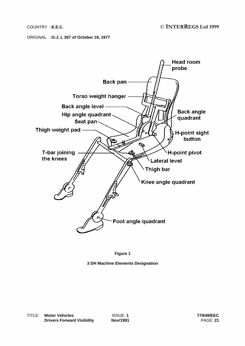
APPENDIX 1
DESCRIPTION OF THE THREE DIMENSIONAL "H" POINT MACHINE (1)
(3 DH MACHINE)
1. Back and seat pans
The back and seat pans are constructed of reinforced plastic and metal; they stimulate thehuman torso and thigh and are mechanically hinged at the "H" point. A quadrant is fastened tothe probe hinged at the "H" point to measure the actual torso angle. An adjustable thigh bar,attached to the seat pan, establishes the thigh centreline and serves as a baseline for the hipangle quadrant.
2. Body and leg elements
Lower leg segments are connected to the seat pan assembly at the T-bar joining the knees,which is a lateral extension of the adjustable thigh bar. Quadrants are incorporated in the lowerleg segments to measure knee angles. Shoe and foot assemblies are calibrated to measurethe foot angle. Two spirit levels orient the device in space. Body element weights are placedat the corresponding centres of gravity to provide seat penetration equivalent to a 76 kg male.All joints of the 3 DH machine should be checked for free movement without encounteringnoticeable friction.
(1) The machine corresponds to that described in ISO Standard 6549-1980.
For details of the construction of the 3 DH machine refer to Society of Automotive Engineers (SAE), 400 Commonwealth Drive,Warrendale, Pensylvania 15096, United States of America.
COUNTRY :E.E.C. © ,17(55(*6#/WG#4<<<ORIGINAL :O.J. L 267 of October 19, 1977
TITLE: Motor Vehicles ISSUE: 1 77/649/EECDrivers Forward Visibility Nov/1991 PAGE: 21
Figure 1
3 DH Machine Elements Designation

COUNTRY :E.E.C. © ,17(55(*6#/WG#4<<<ORIGINAL :O.J. L 267 of October 19, 1977
TITLE: Motor Vehicles ISSUE: 1 77/649/EECDrivers Forward Visibility Nov/1991 PAGE: 22
Figure 2
Dimensions of the 3 DH Machine Elements and Load Distribution

COUNTRY :E.E.C. © ,17(55(*6#/WG#4<<<ORIGINAL :O.J. L 267 of October 19, 1977
TITLE: Motor Vehicles ISSUE: 1 77/649/EECDrivers Forward Visibility Nov/1991 PAGE: 23
APPENDIX 2
THREE-DIMENSIONAL REFERENCE SYSTEM
1. The three-dimensional reference system is defined by three orthogonal planes established bythe vehicle manufacturer (see Figure). (1)
2. The vehicle measuring attitude is established by positioning the vehicle on the supportingsurface such that the coordinates of the fiducial marks correspond to the values indicated bythe manufacturer.
3. The coordinates of the "R" point and the "H" point are established in relation to the fiducial marksdefined by the vehicle manufacturer.
(1) The reference system corresponds to ISO standard 4130, 1978.

COUNTRY :E.E.C. © ,17(55(*6#/WG#4<<<ORIGINAL :O.J. L 267 of October 19, 1977
TITLE: Motor Vehicles ISSUE: 1 77/649/EECDrivers Forward Visibility Nov/1991 PAGE: 24
APPENDIX 3
REFERENCE DATA CONCERNING SEATING POSITIONS
1. Coding of reference data
Reference data are listed consecutively for each seating position. Seating positions areidentified by a two-digit code. The first digit is an Arabic numeral and designates the row ofseats, counting from the front to the rear of the vehicle. The second digit is a capital letter whichdesignates the location of the seating position in a row, as viewed in the direction of forwardmotion of the vehicle; the following letters shall be used:
L = leftC = centreR = right
2. Description of vehicle measuring attitude
2.1. Co-ordinates of fiducial marks
X ..........................................................Y ..........................................................Z ..........................................................
3. List of reference data
3.1. Seating position: .....................................................................................
3.1.1. Co-ordinates of "R" point
X ..........................................................Y ..........................................................Z ..........................................................
3.1.2. Design torso angle:.................................................................................
3.1.3. Specification for seat adjustment (1)
horizontal: ............................................
vertical: ................................................
angular:................................................
torso angle:..........................................
Note: List reference data for further seating positions under 3.2, 3.3, etc.
(1) Strike out what does not apply.
COUNTRY :E.E.C. © ,17(55(*6#/WG#4<<<ORIGINAL :O.J. L 267 of October 19, 1977
TITLE: Motor Vehicles ISSUE: 1 77/649/EECDrivers Forward Visibility Nov/1991 PAGE: 25
ANNEX IV
METHOD FOR DETERMINING THE DIMENSIONAL RELATIONSHIPS BETWEEN THE VEHICLE'SPRIMARY REFERENCE MARKS AND THE THREE-DIMENSIONAL
REFERENCE GRID
1. RELATIONSHIP BETWEEN REFERENCE GRID AND VEHICLE PRIMARY REFERENCEMARKS
To verify specific dimensions on or within a vehicle submitted for type-approval in accordancewith this Directive, the relationship between the coordinates of the three-dimensional referencegrid, defined in 2.3 of Annex I, which has been laid out at the initial vehicle-design stage, andthe positions of the primary reference marks defined in 2.4 of Annex I, must be establishedaccurately so that specific points on the vehicle manufacturer's drawings can be identified onan actual vehicle produced from those drawings.
2. METHOD FOR ESTABLISHING RELATIONSHIP OF REFERENCE GRID TO REFERENCEMARKS
For this purpose, a ground reference plane shall be constructed which is marked with the X-Xmeasurement and the Y-Y measurement. The method of achieving this is set out in Figure 6of the Appendix to this Annex, the reference plane being a hard, flat, level surface upon whichthe vehicle stands, and which has two measuring scales firmly fixed to its surface; these shallbe graduated in millimetres, the X-X scale being not less than eight metres long, and the Y-Yscale not less than four metres long. The two scales must be set at right angles to each otheras shown in Figure 6 of the Appendix to this Annex. The intersection of these scales is groundzero.
3. EXAMINATION OF THE REFERENCE PLANE
In order to provide for minor variations in the level of the reference plane or test area, it will benecessary to measure the deviations from ground zero along both the X and Y scales atintervals of 250 mm and to record the readings obtained so that corrections can be made whenchecking the vehicle.
4. ACTUAL TEST ATTITUDE
In order to provide for minor changes in suspension height, etc., it will be necessary to haveavailable a means of bringing the primary reference marks to the correct coordinate positionsrelative to the design attitude before further measurements are taken. In addition, it must bepossible to make minor lateral and/or longitudinal adjustments of the vehicle's position so as toplace it accurately in relation to the reference grid.
5. RESULTS
The vehicle having been correctly placed relative to the reference grid and in its design attitude,the site of the necessary points for studying the forward visibility requirements can be readilydetermined.
Test methods to determine these requirements may include the use of theodolites, light sourcesor shadow devices, or any other method which can be shown to give equivalent results.

COUNTRY :E.E.C. © ,17(55(*6#/WG#4<<<ORIGINAL :O.J. L 267 of October 19, 1977
TITLE: Motor Vehicles ISSUE: 1 77/649/EECDrivers Forward Visibility Nov/1991 PAGE: 26
(1) Line tracing the median longitudinal plane of the vehicle.(2) Line tracing the vertical plane passing through R.(3) Line tracing the vertical plane passing through V1 and V2.
Figure 1
Determination of V Points

COUNTRY :E.E.C. © ,17(55(*6#/WG#4<<<ORIGINAL :O.J. L 267 of October 19, 1977
TITLE: Motor Vehicles ISSUE: 1 77/649/EECDrivers Forward Visibility Nov/1991 PAGE: 27
Figure 2

COUNTRY :E.E.C. © ,17(55(*6#/WG#4<<<ORIGINAL :O.J. L 267 of October 19, 1977
TITLE: Motor Vehicles ISSUE: 1 77/649/EECDrivers Forward Visibility Nov/1991 PAGE: 28
Figure 3

COUNTRY :E.E.C. © ,17(55(*6#/WG#4<<<ORIGINAL :O.J. L 267 of October 19, 1977
TITLE: Motor Vehicles ISSUE: 1 77/649/EECDrivers Forward Visibility Nov/1991 PAGE: 29
Figure 4
Evaluation of Obstructions in the 180 °°°° Forward Direct Fieldof Vision of the Driver

COUNTRY :E.E.C. © ,17(55(*6#/WG#4<<<ORIGINAL :O.J. L 267 of October 19, 1977
TITLE: Motor Vehicles ISSUE: 1 77/649/EECDrivers Forward Visibility Nov/1991 PAGE: 30
Figure 5
Dimensional Diagram showing Relative Positionsof E Points and P Points

COUNTRY :E.E.C. © ,17(55(*6#/WG#4<<<ORIGINAL :O.J. L 267 of October 19, 1977
TITLE: Motor Vehicles ISSUE: 1 77/649/EECDrivers Forward Visibility Nov/1991 PAGE: 31
Figure 6
Three-Dimensional Reference Grid

COUNTRY :E.E.C. © ,17(55(*6#/WG#4<<<ORIGINAL :O.J. L 267 of October 19, 1977
TITLE: Motor Vehicles ISSUE: 1 77/649/EECDrivers Forward Visibility Nov/1991 PAGE: 32
Figure 7
Level Work Space

COUNTRY :E.E.C. © ,17(55(*6#/WG#4<<<ORIGINAL :O.J. L 267 of October 19, 1977
TITLE: Motor Vehicles ISSUE: 1 77/649/EECDrivers Forward Visibility Nov/1991 PAGE: 33
ANNEX V
MODEL
(Maximum format: A 4 (210 x 297 mm))
ANNEX TO THE EEC VEHICLE TYPE-APPROVAL CERTIFICATE WITH REGARDTO THE DRIVER'S FIELD OF VISION
(Article 4 (2) and Article 10 of the Council Directive 70/156/EEC of 6 February 1970on the approximation of the laws of the Member States relating to the type-approval
of motor vehicles and their trailers)
EEC type-approval No.....................................................................................................................................
1. Trade name or mark of the vehicle.......................................................................................................
2. Vehicle type...........................................................................................................................................
3. Manufacturer's name and address .......................................................................................................
4. Where applicable, name and address of manufacturer's authorized representative............................
..............................................................................................................................................................
5. Brief description of the vehicle..............................................................................................................
6. Identification data for R point of driver's designated seating position in relation to position of primaryreference marks....................................................................................................................................
..............................................................................................................................................................
7. Identifications, sites and relative positions of primary reference marks ...............................................
8. Vehicle submitted for type-approval on.................................................................................................
9. Technical service conducting type-approval tests ................................................................................
10. Date of report issued by that service ....................................................................................................
11. Number of report issued by that service ...............................................................................................
12. Type-approval in respect of the driver's field of vision is granted/refused (1)
(1) Delete as applicable.
Name of administration
COUNTRY :E.E.C. © ,17(55(*6#/WG#4<<<ORIGINAL :O.J. L 267 of October 19, 1977
TITLE: Motor Vehicles ISSUE: 1 77/649/EECDrivers Forward Visibility Nov/1991 PAGE: 34
13. Place .....................................................................................................................................................
14. Date ......................................................................................................................................................
15. Signature...............................................................................................................................................
16. The following documents, bearing the type-approval number shown above, are annexed to thiscertificate:
.................................................. dimensional drawings
.................................................. exploded view, of photograph(s) of the passenger compartment
17. Remarks ...............................................................................................................................................

COUNTRY :E.E.C. © ,17(55(*6#/WG#4<<<ORIGINAL :O.J. L 231 of August 15, 1981
TITLE: Motor Vehicles ISSUE: 1 81/643/EECDrivers Forward Visibility Nov/1991 PAGE: 1
COMMISSION DIRECTIVE
of July 29, 1981
adapting to technical progress Council Directive 77/649/EEC on the approximation of thelaws of the Member States relating to the field of vision of motor vehicle drivers
(81/643/EEC)
THE COMMISSION OF THE EUROPEAN COMMUNITIES,
Having regard to the Treaty establishing the European Economic Community,
Having regard to Council Directive 70/156/EEC of February 6, 1970 on the approximation of the laws of theMember States relating to the type-approval of motor vehicles and their trailers (1), as last amended byDirective 80/1297/EEC (2), and in particular Article 11 thereof,
Having regard to Council Directive 77/649/EEC of September 27, 1977 on the approximation of the laws ofthe Member States relating to the field of vision of motor vehicle drivers (3), and in particular Article 5 thereof,
Whereas, in the light of experience gained, it has been established that the present wording of Item 5.1.3 ofAnnex I to Directive 77/649/EEC relating to the field of vision of Drivers of category M1 vehicles, as definedin Annex I to Directive 70/156/EEC, imposes limitations on the design of vehicles; whereas this has resultedin the withholding of type approval from vehicles bearing obstructions which do not in any way restrict thedriver's field of vision;
Whereas the measures provided for in this Directive are in accordance with the opinion of the Committee onthe Adaptation to Technical Progress of the Directive aimed at the Removal of Technical Barriers to Tradein the motor vehicles sector,
HAS ADOPTED THIS DIRECTIVE:
ARTICLE 1
All relevant amendments have been incorporated in Directive 77/649/EEC.
ARTICLE 2
Member States shall bring into force the provisions necessary in order to comply with this Directive not laterthan December 31, 1982 and shall forthwith inform the Commission thereof.
(1)
OJ No. L 42, 23.2.1970, p. 1.(2)
OJ No. L 375, 31.12.1980, p. 34.(3)
OJ No. L 267, 19.10.1977, p. 1.

COUNTRY :E.E.C. © ,17(55(*6#/WG#4<<<ORIGINAL :O.J. L 231 of August 15, 1981
TITLE: Motor Vehicles ISSUE: 1 81/643/EECDrivers Forward Visibility Nov/1991 PAGE: 2
ARTICLE 3
This Directive is addressed to the Member States.
Done at Brussels, July 29, 1981.
For the Commission
Karl-Heinz NARJES
Member of the Commission
COUNTRY :E.E.C. © ,17(55(*6#/WG#4<<<ORIGINAL :O.J. L 181 of July 12, 1988
TITLE: Motor Vehicles ISSUE: 1 88/366/EECDrivers Forward Visibility Nov/1991 PAGE: 1
COMMISSION DIRECTIVE
of May 17, 1988
on the adaptation to technical progress of Council Directive 77/649/EEC on theapproximation of the laws of the Member States relating to the
field of vision of motor vehicle drivers
(88/366/EEC)
THE COMMISSION OF THE EUROPEAN COMMUNITIES,
Having regard to the Treaty establishing the European Economic Community,
Having regard to the Council Regulation (EEC) No. 70/156/EEC of February 6, 1970 on the approximationof the laws of the Member States relating to the type-approval of motor vehicles and their trailers (1), as lastamended by Directive 87/403/EEC (2), and in particular Article 11 thereof,
Having regard to the Council Regulation (EEC) No. 77/649/EEC of September 27, 1977 on the approximationof the laws of the Member States relating to the field of vision of motor vehicle drivers (3), as amended byDirective 81/643/EEC (4), and in particular Article 5 thereof,
Whereas vehicle design has developed, in particular as a result of the influence of aerodynamic researchintended to save fuel, which has often caused windscreen posts to be quite considerably raked; whereas thecurrent requirements relating to the binocular obstruction due to windscreen posts should be amended inorder to alleviate the difficulties encountered by manufacturers in producing vehicles having optimum dragcoefficients (Cd);
Whereas practical experience has demonstrated the need also to amend certain requirements relating 'toradio aerial' and 'defrosting/demisting' conductors which are integral with the windscreen in order to enableoptimum quality and performance to be obtained which are compatible with highest-performance radioinstallations, and to permit an increase in the performance and efficiency of windscreen defrosting anddemisting while maintaining good optical quality and without obstructing the field of vision;
Whereas the measures provided for in this Directive are in accordance with the opinion of the Committee onthe Adaptation to Technical Progress of the Directive aimed at the Removal of Technical Barriers to Tradein the Motor Vehicle Sector,
HAS ADOPTED THIS DIRECTIVE:
ARTICLE 1
All relevant amendments have been incorporated into Directive 77/649/EEC.
(1)
OJ No. L 42, 23.2.1970, p. 1.(2)
OJ No. L 220, 8.8.1987, p. 44.(3)
OJ No. L 267, 19.10.1977, p. 1.(4)
OJ No. L 231, 15.8.1981, p. 41.

COUNTRY :E.E.C. © ,17(55(*6#/WG#4<<<ORIGINAL :O.J. L 181 of July 12, 1988
TITLE: Motor Vehicles ISSUE: 1 88/366/EECDrivers Forward Visibility Nov/1991 PAGE: 2
ARTICLE 2
Member States shall bring into force the provisions necessary in order to comply with this Directive not laterthan October 1, 1988 and shall forthwith inform the Commission thereof.
ARTICLE 3
This Directive is addressed to the Member States.
Done at Brussels, May 17, 1988.
For the Commission
COCKFIELD
Vice-President

COUNTRY :E.E.C. © ,17(55(*6#/WG#4<<<ORIGINAL :O.J. L 341 of December 6, 1990
TITLE: Motor Vehicles ISSUE: 1 90/630/EECDrivers Forward Visibility Nov/1991 PAGE: 1
COMMISSION DIRECTIVE
of October 30, 1990
adapting to technical progress of Council Directive 77/649/EEC on theapproximation of the laws of the Member States relating to the
field of vision of motor vehicle drivers
(90/630/EEC)
THE COMMISSION OF THE EUROPEAN COMMUNITIES,
Having regard to the Treaty establishing the European Economic Community,
Having regard to Council Directive 77/649/EEC of September 27, 1977 on the approximation of the laws ofthe Member States relating to the field of vision of motor vehicles (1), as last amended by CommissionDirective 88/366/EEC (2), and in particular Article 5 thereof,
Whereas, in view of experience gained and of the state of the art, it is now appropriate to render more precisethe test procedure laid down in Annex III to Directive 77/649/EEC, and in particular, to align it to the latestdevelopments in the United Nations Economic Commission for Europe;
Whereas the provisions of this Directive are in accordance with the opinion of the Committee on theAdaptation to Technical Progress of the Directives on the removal of technical barriers to trade in motorvehicles,
HAS ADOPTED THIS DIRECTIVE:
ARTICLE 1
All relevant amendments have been incorporated into Directive 77/649/EEC.
ARTICLE 2
1. With effect from May 1, 1991 no Member State may, on grounds relating to field of vision:
refuse, in respect of a type of vehicle, to grant EEC type-approval, to issue the copy of thecertificate provided for in the last indent of Article 10(1) of Directive 70/156/EEC (3), or to grantnational type-approval, or
prohibit the entry into service of vehicles
where the field of vision of drivers of such type of vehicle or of such vehicles has been determined inaccordance with Directive 77/649/EEC, as amended by this Directive.
(1)
OJ No. L 267, 19.10.1977, p. 1.(2)
OJ No. L 181, 12.7.1988, p. 40.(3)
OJ No. L 42, 23.2.1970, p. 1.
COUNTRY :E.E.C. © ,17(55(*6#/WG#4<<<ORIGINAL :O.J. L 341 of December 6, 1990
TITLE: Motor Vehicles ISSUE: 1 90/630/EECDrivers Forward Visibility Nov/1991 PAGE: 2
2. With effect from October 1, 1991 Member States:
shall no longer issue the copy of the certificate provided for in the last indent of Article 10(1) ofDirective 70/156/EEC in respect of a type of vehicle of which the driver's field of vision has notbeen determined in accordance with Directive 77/649/EEC, as amended by this Directive,
may refuse to grant national type-approval of a type of vehicle of which the driver's field of visionhas not been determined in accordance with Directive 77/649/EEC, as amended by thisDirective.
ARTICLE 3
Member States shall implement the provisions necessary in order to comply with this Directive beforeMay 1, 1991. They shall forthwith inform the Commission thereof.
When Member States adopt these provisions, these shall contain a reference to this Directive or shall beaccompanied by such reference at the time of their official publication. The procedure for such referenceshall be adopted by Member States.
ARTICLE 4
This Directive is addressed to the Member States.
Done at Brussels, October 30, 1990.
For the Commission
Martin BANGEMANN
Vice-President