formulating constitutive stress-strain relations for flexural design
TRANSCRIPT

Formulating Constitutive Stress-Strain Relations for Flexural Design of Ultra-High-Performance Fiber-Reinforced Concrete
Kaka et al. 1
Formulating Constitutive Stress-Strain Relations for Flexural Design of Ultra-High-Performance Fiber-
Reinforced Concrete
Venkatesh Babu Kaka, Graduate Student, University of Texas at Arlington, TX Jinsup Kim, Post-doctoral Research Fellow, University of Texas at Arlington, TX
Shih-Ho Chao, Associate Professor, University of Texas at Arlington, TX
Abstract: Ultra-high-performance fiber-reinforced concrete (UHP-FRC) has high compressive strength (> 22 ksi [150 MPa]) and exceptional compressive ductility. The use of UHP-FRC provides new opportunities for future infrastructure. However, structural design criteria have not been developed to fully utilize UHP-FRC’s excellent mechanical properties. Maximum useable compressive strain, εcu, specified in the current design codes (ACI 318 Building Code and AASHTO LRFD Bridge Design Specifications) are limited to 0.003 for conventional plain concrete with little ductility and a maximum compressive strength of about 10 (69 MPa) and 15 ksi (103 MPa) for ACI 318 and AASHTO LRFD Specifications, respectively. This maximum concrete compressive strain directly limits the amount of longitudinal reinforcement that could be used in flexural members, which in turn limits the flexural capacity of the members. Since the maximum useable strains of UHP-FRC are 5 to 10 times of that of plain concrete, it is apparent that the maximum compressive strain used for the current design needs to be reevaluated for UHP-FRC. In addition, unlike plain concrete, the tensile strength of UHP-FRC can also contribute to its bending capacity. This research investigated the flexural behavior of a UHP-FRC beam reinforced with flexural reinforcement five times greater than that allowed by ACI or AASHTO provisions for tension-controlled conventional reinforced concrete beams. The large amount of reinforcement also significantly affected the tensile behavior of UHP-FRC due to the tension-stiffening effect.
Keywords: UHP-FRC, Beam, Maximum concrete compressive strain, Tension-controlled, Tension-stiffening effect
First International Interactive Symposium on UHPC – 2016

Formulating Constitutive Stress-Strain Relations for Flexural Design of Ultra-High-Performance Fiber-Reinforced Concrete
Kaka et al. 2
1. Introduction
Ultra-high-performance fiber-reinforced concrete (UHP-FRC) offers a new way to design reinforced concrete flexural members due to its superior mechanical properties as compared to conventional concrete. Fig. 1 shows typical compressive and tensile stress-strain relations of one of the UHP-FRC materials developed at UT Arlington. The maximum usable compressive strain (at a post-peak stress of approximately 80% of the peak stress), εcu, is approximately 0.015. For plain concrete, the compressive strain at this level of stress is 0.003. ACI 318 (ACI, 2014) and AASHTO LRFD (AASHTO, 2014) use 0.003 as the design maximum strain at crushing of concrete. Due to this small strain capacity of plain concrete, only a small amount of longitudinal reinforcement could be used in order to ensure that the flexural member is tension-controlled. For a tension-controlled beam section, the tensile strain in the extreme tension reinforcement (closest to the tension face) is sufficiently large (≥ 0.005); therefore, the beam shows a large deflection as a warning before failure occurs. If the concrete compressive strain can be 5 to 10 times greater, the beam could be more efficiently utilized by placing considerably higher amount of longitudinal reinforcement while still maintaining tension-controlled behavior.
Direct tension test (no rebar in the specimen) indicated that UHP-FRC can crack at a small strain but it can also maintain high tensile strength up to a strain of 0.01. On the other hand, prior research showed that the presence of steel reinforcement in structural members enhances the cracking distribution and tensile ductility of steel fiber-reinforced concrete (SFRC) due to the tension-stiffening effect (Chao et al., 2009; Aghdasi et al., 2015). Therefore, adding a large amount of longitudinal reinforcement not only increases the flexural strength of UHP-FRC beams, but it could also possibly enhance the mechanical behavior of UHP-FRC on the tensile side of the beam.
Figure 1. Typical stress-strain response of UHP-FRC: (a) Compression test; (b) Direct tension test
2. Experimental Programs
2.1. Specimen Design
Two simply supported beams, one made of reinforced concrete (RC) and one made of UHP-FRC were monotonically loaded up to failure (Fig. 2). Both beam specimens had a width of 9 in. (229 mm), a height of 16 in. (406 mm), and a span length of 134 in. (3404 mm). For both specimens, the shear span to effective-depth ratio, a/d ratio, was maintained at 4.75. The UHP-FRC used in
First International Interactive Symposium on UHPC – 2016

Formulating Constitutive Stress-Strain Relations for Flexural Design of Ultra-High-Performance Fiber-Reinforced Concrete
Kaka et al. 3
this study had 3.0% micro straight steel fibers (length to dia. ratio (l/d = 71.4), l = 12.5 mm, d = 0.175 mm, and tensile strength = 2200 MPa). The UHP-FRC mix was nearly self-consolidating requiring no vibration resulting in a very smooth finish.
(a)
(b)
Figure 2. Reinforcement details of (a) RC beam; (b) UHP-FRC beam. Unit: inch (1 in. = 25.4 mm)
Material tests for UHP-FRC both in compression and tension were obtained from uniaxial compression testing on 2.78 in. (71 mm) cubes and direct tension testing on dog-bone shaped specimens, respectively. Cubes were tested by a load-controlled procedure with a constant loading rate of 400 lb/sec (1779 N/sec) up to failure. Strains were measured by two linear variable differential transformers (LVDTs) on both sides of the cubes. The dog-bone shaped tensile specimens were tested under displacement-controlled procedure with a constant displacement rate of 0.005 in./min (0.127 mm/min) throughout the testing. Strains were measured in the same way by two LVDTs on both sides with a gauge length of 4.75 in. (121 mm). The results are shown in Fig. 1.
The RC beam was designed to have the highest amount of longitudinal reinforcement while still maintaining tension-controlled behavior (Fig. 3a) according to ACI 318 and AASHTO LRFD provisions. That is, the extreme tensile reinforcement reached 0.005 strain when the maximum concrete strain was 0.003 (Fig. 3b). This led to the use of nine No. 5 rebars, corresponding to a flexural reinforcement ratio of ρ = 2.58% (Fig. 2a). Shear reinforcement was provided outside of
First International Interactive Symposium on UHPC – 2016

Formulating Constitutive Stress-Strain Relations for Flexural Design of Ultra-High-Performance Fiber-Reinforced Concrete
Kaka et al. 4
the constant moment region to ensure that failure was not governed by shear. Design compressive strength of the RC beam was 5,000 psi (34.5 MPa). For UHP-FRC beam, the design compressive strength of UHP-FRC was 22,000 psi (152 MPa) and the maximum usable compressive strain, εcu, was taken as 0.015. The flexural reinforcement ratio was five times that of the RC beam which results in a ratio of ρ = 13%, corresponding to nine No. 11 rebars (Fig. 2b and Table 1). To simplify the design, the β1 factor was assumed the same for plain concrete as recommended by ACI 318 and AASHTO LRFD. Neglecting the contribution of UHP-FRC on the tension side, as a conservative assumption for design, it was determined that the tensile strain of the extreme rebars in the UHP-FRC beam was much larger (0.013) than the tension-controlled limit (0.005), even with considerably higher amount of reinforcement (Fig. 3c). Shear reinforcement outside of the constant moment region was designed by conservatively assuming the shear capacity of UHP-FRC
is '3.5 cf . Table 2 summarizes the design parameters and predicted strengths for various designs.
Transition Compression- ControlledTension - Controlled
t0.005 0.002
cu
t cu t
c
d
Value of Ultimate Compressive
Strain in concrete (cu) = 0.003
(a)
(b) (c)
Figure 3. (a) ACI 318 and AASHTO design criteria; (b) strain profile of RC beam; (c) strain profile UHP-FRC beam
Table 1. Design properties of specimens
Specimen Width (b) in. (mm)
Height (h) in. (mm)
Effective depth (d) in.
(mm)
(%)
1 '
cf
psi (MPa) cu
RC 9 (229) 16 (406) 12 (305) 2.58 0.8 5000 (34.5) 0.003
UHP-FRC 9 (229) 16 (406) 12 (305) 13.0 0.65 22000 (152) 0.015
First International Interactive Symposium on UHPC – 2016
Formulating Constitutive Stress-Strain Relations for Flexural Design of Ultra-High-Performance Fiber-Reinforced Concrete
Kaka et al. 5
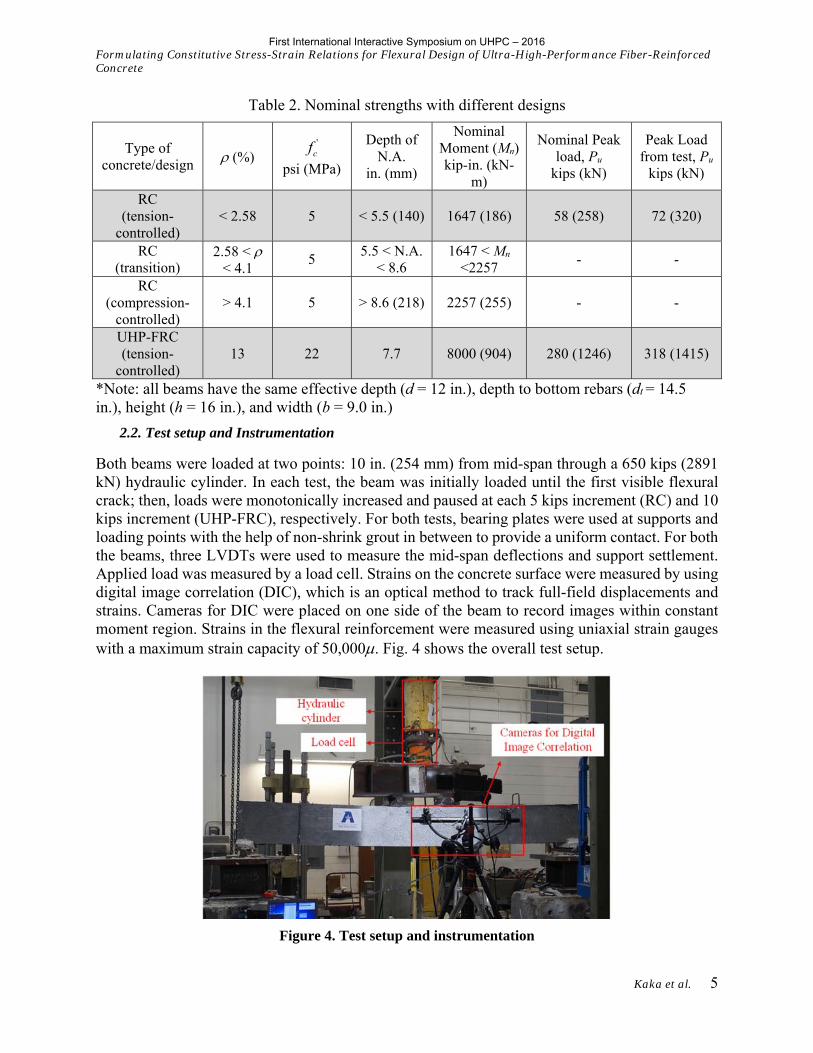
Table 2. Nominal strengths with different designs
Type of concrete/design (%)
'cf
psi (MPa)
Depth of N.A.
in. (mm)
Nominal Moment (Mn)
kip-in. (kN-m)
Nominal Peak load, Pu
kips (kN)
Peak Load from test, Pu
kips (kN)
RC (tension-
controlled) < 2.58 5 < 5.5 (140) 1647 (186) 58 (258) 72 (320)
RC (transition)
2.58 < < 4.1
5 5.5 < N.A.
< 8.6 1647 < Mn
<2257 - -
RC (compression-
controlled) > 4.1 5 > 8.6 (218) 2257 (255) - -
UHP-FRC (tension-
controlled) 13 22 7.7 8000 (904) 280 (1246) 318 (1415)
*Note: all beams have the same effective depth (d = 12 in.), depth to bottom rebars (dt = 14.5 in.), height (h = 16 in.), and width (b = 9.0 in.)
2.2. Test setup and Instrumentation
Both beams were loaded at two points: 10 in. (254 mm) from mid-span through a 650 kips (2891 kN) hydraulic cylinder. In each test, the beam was initially loaded until the first visible flexural crack; then, loads were monotonically increased and paused at each 5 kips increment (RC) and 10 kips increment (UHP-FRC), respectively. For both tests, bearing plates were used at supports and loading points with the help of non-shrink grout in between to provide a uniform contact. For both the beams, three LVDTs were used to measure the mid-span deflections and support settlement. Applied load was measured by a load cell. Strains on the concrete surface were measured by using digital image correlation (DIC), which is an optical method to track full-field displacements and strains. Cameras for DIC were placed on one side of the beam to record images within constant moment region. Strains in the flexural reinforcement were measured using uniaxial strain gauges with a maximum strain capacity of 50,000. Fig. 4 shows the overall test setup.
Figure 4. Test setup and instrumentation
First International Interactive Symposium on UHPC – 2016

Formulating Constitutive Stress-Strain Relations for Flexural Design of Ultra-High-Performance Fiber-Reinforced Concrete
Kaka et al. 6
3. Experimental Results
In the RC beam, the first flexural crack was observed at a stress on the tension side nearly equal to the modulus of rupture of concrete (load: 12.0 kips [53kN]). Whereas in the UHP-FRC beam, the first flexural crack was observed at a very high load of 300 kips. As shown in Fig. 5, UHP-FRC maintained a nearly linear uncracked behavior up to 250 kips (1112 kN), thereby maintaining a very high stiffness up to 80% of the peak strength. The concrete compressive strains in the RC and UHP-FRC beams at their peak strength were measured by DIC as 0.006 and 0.025, respectively. This indicates that using a strain εcu = 0.015 to design UHP-FRC is on the conservative side and provides a sufficient safety margin. The ultimate strength of UHP-FRC, 318 kips (1415 kN), is 4.4 times that of an RC beam (72 kips [320 kN]). Fig. 5 also shows that the UHP-FRC beam had decent ductility, even with a reinforcement ratio five times greater than that of the RC beam. This indicates that using UHP-FRC is able to largely increase capacity and stiffness while maintaining a small self-weight.
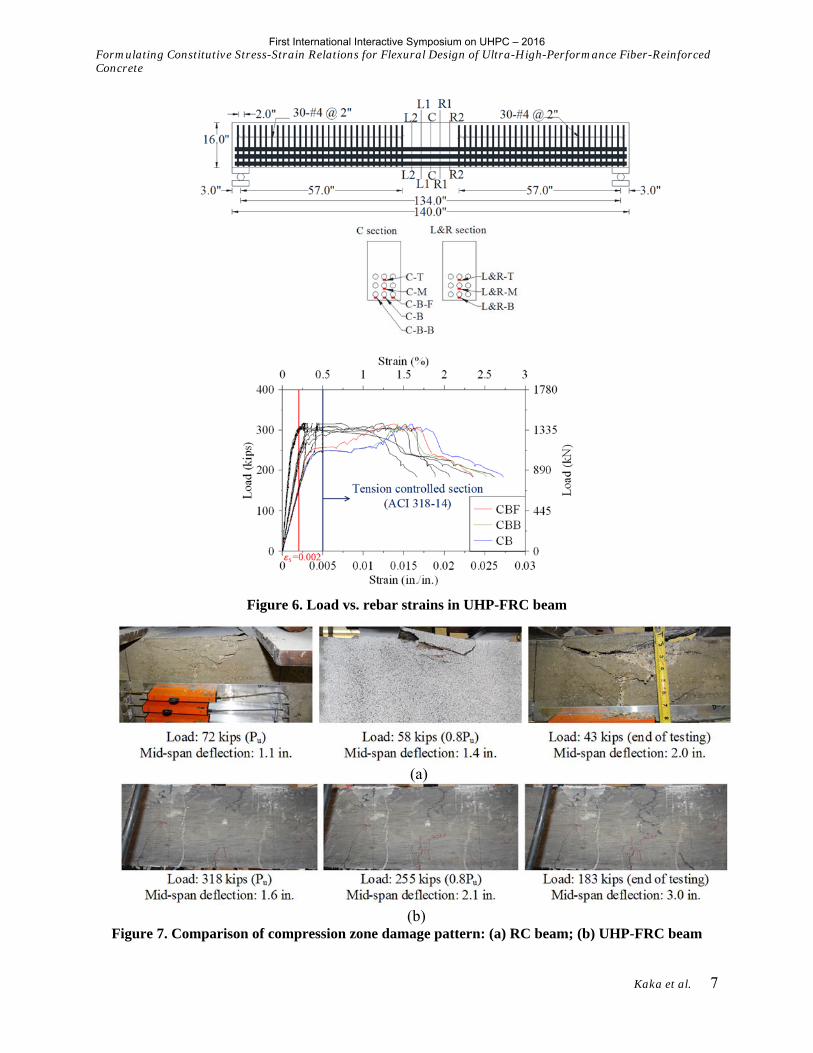
Fig. 6 shows that the strains in the bottom rebars all reached 0.013 (estimated as shown in Fig. 3c) and went well beyond the tension-controlled limit of 0.005. At 0.005 strain in longitudinal rebars, the concrete compressive strain observed in UHP-FRC beam was 0.004, which was much less than the design compressive strain, εcu = 0.015. UHP-FRC’s high compressive ductility can be seen in Fig. 7. While plain concrete suffered severe crushing and spalling, steel fibers in UHP-FRC was able to keep the concrete intact.
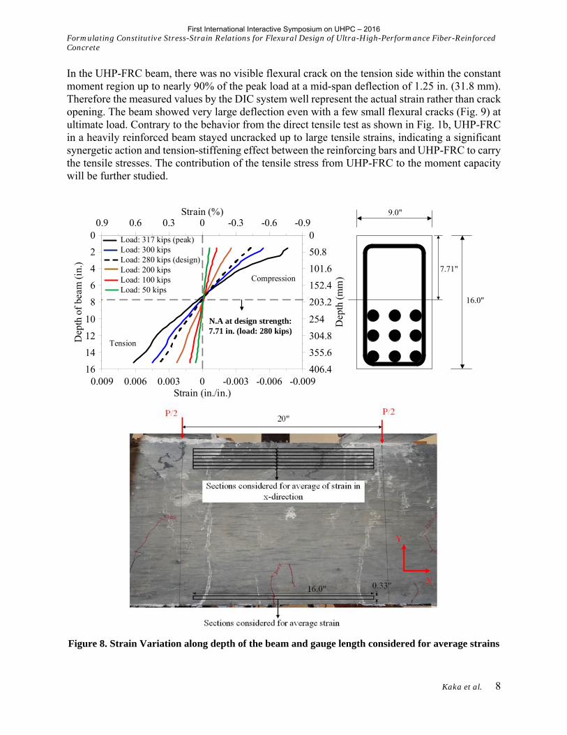
Fig. 8 shows the concrete surface compressive and tensile strains in the UHP-FRC beam as measured by the DIC system. Strain variations along the depth of the beam were acquired from 42 layers (each layer of 0.33 in. [8.4 mm]thick) within the constant moment region (20 in. [508 mm]) using DIC. Strains measured in each layer were averaged over a length of 16.0 in. (406 mm). The first layer on the compression zone started at 1.5 in. (38.1 mm) below the top fiber, and the first in the tension zone started at 0.77 in. (20 mm) above the extreme tension fiber.
Figure 5. Load vs. mid-span deflection responses of RC and UHP-FRC beams
First International Interactive Symposium on UHPC – 2016
Formulating Constitutive Stress-Strain Relations for Flexural Design of Ultra-High-Performance Fiber-Reinforced Concrete
Kaka et al. 7
Figure 6. Load vs. rebar strains in UHP-FRC beam
(a)
(b)
Figure 7. Comparison of compression zone damage pattern: (a) RC beam; (b) UHP-FRC beam
First International Interactive Symposium on UHPC – 2016
Formulating Constitutive Stress-Strain Relations for Flexural Design of Ultra-High-Performance Fiber-Reinforced Concrete
Kaka et al. 8
In the UHP-FRC beam, there was no visible flexural crack on the tension side within the constant moment region up to nearly 90% of the peak load at a mid-span deflection of 1.25 in. (31.8 mm). Therefore the measured values by the DIC system well represent the actual strain rather than crack opening. The beam showed very large deflection even with a few small flexural cracks (Fig. 9) at ultimate load. Contrary to the behavior from the direct tensile test as shown in Fig. 1b, UHP-FRC in a heavily reinforced beam stayed uncracked up to large tensile strains, indicating a significant synergetic action and tension-stiffening effect between the reinforcing bars and UHP-FRC to carry the tensile stresses. The contribution of the tensile stress from UHP-FRC to the moment capacity will be further studied.
Load: 317 kips (peak)Load: 300 kipsLoad: 280 kips (design)Load: 200 kipsLoad: 100 kipsLoad: 50 kips
9.0"
16.0"
Compression
Tension
N.A at design strength: 7.71 in. (load: 280 kips)
7.71"
0.009 0.006 0.003 0 -0.003 -0.006 -0.009Strain (in./in.)
16
14
12
10
8
6
4
2
0
Dep
thof
beam
(in.
)
406.4
355.6
304.8
254
203.2
152.4
101.6
50.8
0
Dep
th(m
m)
0.9 0.6 0.3 0 -0.3 -0.6 -0.9Strain (%)
Figure 8. Strain Variation along depth of the beam and gauge length considered for average strains
First International Interactive Symposium on UHPC – 2016

Formulating Constitutive Stress-Strain Relations for Flexural Design of Ultra-High-Performance Fiber-Reinforced Concrete
Kaka et al. 9
Figure 9. Large deflection in UHP-FRC beam
4. Conclusions
1. Considering the high compressive ductility of UHP-FRC, a maximum useable compressive strain εcu = 0.015 can be used for design of flexural members. This leads to a higher load-carrying capacity, which is 4.5 to 5 times greater than that of its counterpart RC beam, designed with tension-controlled behavior as recommended by ACI 318 and AASHTO LRFD Specifications. To simplify the design, other stress block design parameters such as the β1 factor could be the same for plain concrete. Experimental results indicated that longitudinal reinforcing bars in the UHP-FRC beam reached a strain of 0.013 and higher, well beyond the 0.005 threshold for a tension-controlled section.
2. The UHP-FRC beam remained uncracked in the constant moment region up to nearly 90% of the peak load. The beam showed very large deflection even with a few small flexural cracks. This is very different behavior as compared to conventional RC beams, and indicates a significant synergetic action and tension-stiffening effect between the reinforcing bars and UHP-FRC to carry the tensile stresses. The contribution of the tensile stress from UHP-FRC to the moment capacity warrants further study.
5. References
AASHTO, “LRFD Bridge Design Specifications,” 7th edition, American Association of State Highway and Transportation Officials (AASHTO), Washington, D.C., 2014.
ACI Committee 318, Building Code Requirements for Structural Concrete (ACI 318-14) and Commentary (ACI 318-14), American Concrete Institute, Farmington Hills, Michigan, 2014.
Aghdasi, P., Palacios, G., Heid, A.E., and Chao, S.-H., “Mechanical properties of a highly flowable ultra-high-performance fiber-reinforced concrete mixture considering large-size effects,” Proceedings of High Performance Fiber Reinforced Cement Composites (HPFRCC 7), International Workshop, Stuttgart, Germany, June 1-3, 2015, pp. 193-200.
Chao, S.-H.; Liao, W.-C.; Wongtanakitcharoen, T.; and Naaman, A.E., “Large Scale Tensile Tests of High Performance Fiber Reinforced Cement Composites,” High Performance Fiber Reinforced Cement Composites: HPFRCC-5, International Workshop, Mainz, Germany, 2007.
6. Acknowledgements
This research was supported by the U.S. National Science Foundation under Award No. CMMI-1414391.
First International Interactive Symposium on UHPC – 2016