form no. 3324–974 - toro
TRANSCRIPT

Parts Catalog
Ordering Replacement PartsTo order replacement parts, please supply: the partnumber, the quantity, and the description of eachpart desired.
Understanding Reference NumbersEach identified part in an illustration has a referencenumber. The reference number for a part also appears inthe parts list, along with other information about the part.
This catalog uses two special reference number formats,one to indicate parts in a service assembly and anotherto indicate the quantity of a given part in an illustration.
Service Assembly Reference NumbersParts in service assemblies have reference numbers inthe form a:b. The a represents the reference number ofthe entire service assembly and the b represents asequential number unique to each part within the serviceassembly.
For example, a wheel assembly might be identified byreference number 6, the tire by 6:1, the valve by 6:2,and the wheel by 6:3. When you order the assemblyidentified by reference number 6, you receive all partsidentified by reference numbers 6:1, 6:2, and 6:3.However, you may also order any part individually.
Reference numbers of this type appear in illustrationsand in part lists.
Reference Numbers Indicating QuantityIn an illustration, if a reference number indicates morethan one part, the reference number has the form nX y.The n represents the quantity of the part, the X is themultiplication symbol, and the y represents the referencenumber.
For example, in an illustration, the reference number2X 37 means that two of the parts identified by referencenumber 37 are indicated.
The TORO Company — 2000All Rights Reserved
Form No. 3324–974
Z149Z–Master � with 52” Side Discharge MowerModel No. 74179—210000001 and Up
3324–974
2
ContentsDescription Page Description PageFront Frame Assembly 4. . . . . . . . . . . . . . . . . . . . . . . Height of Cut Handle and Plates 6. . . . . . . . . . . . . . . Main Frame 7. . . . . . . . . . . . . . . . . . . . . . . . . . . . . . . . Fuel System Assembly 8. . . . . . . . . . . . . . . . . . . . . . . Parking Brake System Assembly 9. . . . . . . . . . . . . . Motion Control System Assembly 10. . . . . . . . . . . . . . Hydraulic System Assembly 11. . . . . . . . . . . . . . . . . . Pump, Idler and Belt Assembly 12. . . . . . . . . . . . . . . . Engine and Clutch Assembly 13. . . . . . . . . . . . . . . . . . 52” Deck Assembly 14. . . . . . . . . . . . . . . . . . . . . . . . . . 52” Deck Spindle Assembly 15. . . . . . . . . . . . . . . . . . . Idler, Pulley/Lift Strut, Chains Assembly 16. . . . . . . . Electrical System Assembly 17. . . . . . . . . . . . . . . . . . . Cylinder/Crankcase Assembly Kawasaki
FH601V–S07 18. . . . . . . . . . . . . . . . . . . . . . . . . . . . . Cylinder/Crankcase Assembly
Kawasaki FH601V–S07 19. . . . . . . . . . . . . . . . . . . . Valve/Camshaft Assembly
Kawasaki FH601V–S07 20. . . . . . . . . . . . . . . . . . . . Valve/Camshaft Assembly
Kawasaki FH601V–S07 21. . . . . . . . . . . . . . . . . . . . Cooling–Equipment Assembly
Kawasaki FH601V–S07 22. . . . . . . . . . . . . . . . . . . .
Cooling–Equipment AssemblyKawasaki FH601V–S07 23. . . . . . . . . . . . . . . . . . . .
Electric–Equipment AssemblyKawasaki FH601V–S07 24. . . . . . . . . . . . . . . . . . . .
Electric–Equipment AssemblyKawasaki FH601V–S07 25. . . . . . . . . . . . . . . . . . . .
Control–Equipment AssemblyKawasaki FH601V–S07 26. . . . . . . . . . . . . . . . . . . .
Control–Equipment AssemblyKawasaki FH601V–S07 27. . . . . . . . . . . . . . . . . . . .
Carburetor AssemblyKawasaki FH601V–S07 28. . . . . . . . . . . . . . . . . . . .
Carburetor AssemblyKawasaki FH601V–S07 29. . . . . . . . . . . . . . . . . . . .
Piston/Crankshaft AssemblyKawasaki FH601V–S07 30. . . . . . . . . . . . . . . . . . . .
Lubrication–Equipment AssemblyKawasaki FH601V–S07 31. . . . . . . . . . . . . . . . . . . .
Air–Filter/Muffler AssemblyKawasaki FH601V–S07 32. . . . . . . . . . . . . . . . . . . .
Fuel–Tank/Fuel–Valve AssemblyKawasaki FH601V–S07 33. . . . . . . . . . . . . . . . . . . .
Starter/DecalsKawasaki FH601V–S07 34. . . . . . . . . . . . . . . . . . . .
AccessoriesDescription Model / Part No. Description Model / Part No.Recycler Kit 59225. . . . . . . . . . . . . . . . . . . . . . . . . . . . . . Bahaia Mulch Kit 59227. . . . . . . . . . . . . . . . . . . . . . . . . . High Sail Blades
(3 required for improved bagging) 56–2390. . . . . . Bagging System 79460. . . . . . . . . . . . . . . . . . . . . . . . . . . Grass Gobbler 30131. . . . . . . . . . . . . . . . . . . . . . . . . . . .
Striping Kit 30121. . . . . . . . . . . . . . . . . . . . . . . . . . . . . . . High Suspension Seat 74210. . . . . . . . . . . . . . . . . . . . . Heat Shield Kit 99–8922. . . . . . . . . . . . . . . . . . . . . . . . . Oil Drain Valve 99–8923. . . . . . . . . . . . . . . . . . . . . . . . . Hitch Kit 99–8924. . . . . . . . . . . . . . . . . . . . . . . . . . . . . . .

3324–974
3
Part Description AbbreviationsPart descriptions in this catalog may include the following abbreviations.
Abbreviation Meaning Abbreviation MeaningAR as required. . . . . . . . . . . . . . . . . ASM assembly. . . . . . . . . . . . . . . . CARR carriage. . . . . . . . . . . . . . DEG degrees. . . . . . . . . . . . . . . . FH flat head. . . . . . . . . . . . . . . . . GA gauge. . . . . . . . . . . . . . . . . HF hex flange. . . . . . . . . . . . . . . . . HH hex head. . . . . . . . . . . . . . . . . HHF hex head flange. . . . . . . . . . . . . . . . HLH hex lag head. . . . . . . . . . . . . . . . HJ hex jam. . . . . . . . . . . . . . . . . . HOC height-of-cut. . . . . . . . . . . . . . . . HS hex socket. . . . . . . . . . . . . . . . . HSBH hex socket button head. . . . . . . . . . . . . . HSFH hex socket flat head. . . . . . . . . . . . . . . HSH hex socket head. . . . . . . . . . . . . . . . HWH hex washer head. . . . . . . . . . . . . . . HWHTF hex washer head. . . . . . . . . . . . .
thread forming
INC incorporated. . . . . . . . . . . . . . . . . LH left hand. . . . . . . . . . . . . . . . . NI nylon insert. . . . . . . . . . . . . . . . . . PPH Phillips pan head. . . . . . . . . . . . . . . . PTH Phillips truss head. . . . . . . . . . . . . . . . PTO power take off. . . . . . . . . . . . . . . . RH right hand. . . . . . . . . . . . . . . . . SFH slotted fillister head. . . . . . . . . . . . . . . . SHH slotted hex head. . . . . . . . . . . . . . . . SQH square head. . . . . . . . . . . . . . . . SHWH slotted hex washer head. . . . . . . . . . . . . . SPH slotted pan head. . . . . . . . . . . . . . . . SRH slotted round head. . . . . . . . . . . . . . . . STD standard. . . . . . . . . . . . . . . . TAP self tapping. . . . . . . . . . . . . . . . TTH Torx truss head. . . . . . . . . . . . . . . . WH wing head. . . . . . . . . . . . . . . . .
3324–974
4
Sheet No.:2
����
����
��
�����
��
���
���
��������
�
�
�
�
�
����������
���
���
���
�
��
����
�
��
����
�
��
��
��
�
�
�
����
��
�
��
��
����
���� ��
��
����
��
��
�
��
��
�
��
�
��
�
�
����
��
��
�
��
��
��
�����
��
��
�
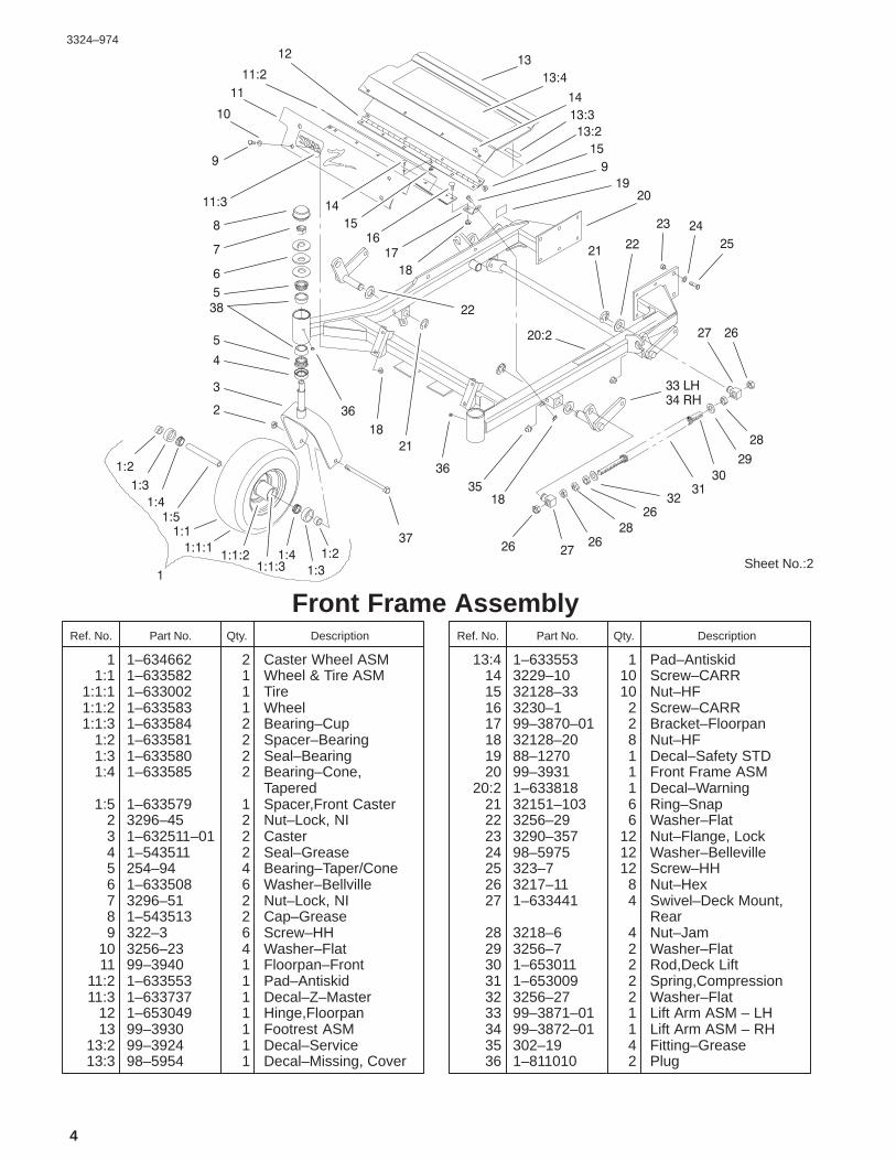
Front Frame AssemblyDescriptionPart No. Qty.Ref. No. DescriptionPart No. Qty.Ref. No.
1 1–634662 2 Caster Wheel ASM1:1 1–633582 1 Wheel & Tire ASM
1:1:1 1–633002 1 Tire1:1:2 1–633583 1 Wheel1:1:3 1–633584 2 Bearing–Cup
1:2 1–633581 2 Spacer–Bearing1:3 1–633580 2 Seal–Bearing1:4 1–633585 2 Bearing–Cone,
Tapered1:5 1–633579 1 Spacer,Front Caster
2 3296–45 2 Nut–Lock, NI3 1–632511–01 2 Caster4 1–543511 2 Seal–Grease5 254–94 4 Bearing–Taper/Cone6 1–633508 6 Washer–Bellville7 3296–51 2 Nut–Lock, NI8 1–543513 2 Cap–Grease9 322–3 6 Screw–HH
10 3256–23 4 Washer–Flat11 99–3940 1 Floorpan–Front
11:2 1–633553 1 Pad–Antiskid11:3 1–633737 1 Decal–Z–Master
12 1–653049 1 Hinge,Floorpan13 99–3930 1 Footrest ASM
13:2 99–3924 1 Decal–Service13:3 98–5954 1 Decal–Missing, Cover
13:4 1–633553 1 Pad–Antiskid14 3229–10 10 Screw–CARR15 32128–33 10 Nut–HF16 3230–1 2 Screw–CARR17 99–3870–01 2 Bracket–Floorpan18 32128–20 8 Nut–HF19 88–1270 1 Decal–Safety STD20 99–3931 1 Front Frame ASM
20:2 1–633818 1 Decal–Warning21 32151–103 6 Ring–Snap22 3256–29 6 Washer–Flat23 3290–357 12 Nut–Flange, Lock24 98–5975 12 Washer–Belleville25 323–7 12 Screw–HH26 3217–11 8 Nut–Hex27 1–633441 4 Swivel–Deck Mount,
Rear28 3218–6 4 Nut–Jam29 3256–7 2 Washer–Flat30 1–653011 2 Rod,Deck Lift31 1–653009 2 Spring,Compression32 3256–27 2 Washer–Flat33 99–3871–01 1 Lift Arm ASM – LH34 99–3872–01 1 Lift Arm ASM – RH35 302–19 4 Fitting–Grease36 1–811010 2 Plug

3324–974
5
Sheet No.:2
����
����
��
�����
��
���
���
��������
�
�
�
�
�
����������
���
���
���
�
��
����
�
��
����
�
��
��
��
�
�
�
����
��
�
��
��
����
���� ��
��
����
��
��
�
��
��
�
��
�
��
�
�
����
��
��
�
��
��
��
�����
��
��
�
Front Frame AssemblyDescriptionPart No. Qty.Ref. No. DescriptionPart No. Qty.Ref. No.
37 325–36 2 Screw–HH38 254–72 4 Bearing–Taper/Cup

3324–974
6
Sheet No.:3
�
����
�
�
��
�
�
��
�
�
�
��
�
�
��
��
�
��
��
�
�
�
��
��
��
�
Height of Cut Handle and PlatesDescriptionPart No. Qty.Ref. No. DescriptionPart No. Qty.Ref. No.
1 323–9 2 Screw–HH2 32151–103 1 Ring–Snap3 3290–357 3 Nut–Flange, Lock4 3296–39 3 Nut–Lock, NI5 1–652235–01 1 Wld,Deck Lift Plate6 1–633080 1 Bushing–Lever, Lift7 1–653230–01 1 Plate–Deck Lift8 1–806005 1 Pin–Hair9 323–6 1 Screw–HH
10 323–13 1 Screw–HH11 1–633082 1 Bushing–Lever, Lift12 1–652023–03 1 Wld,Lift Lever13 1–633295 1 Grip–Lever, Lift14 1–633097 1 Pin–Hitch w/Lanyard15 302–19 1 Fitting–Grease16 1–806003 2 Pin–Cotter, Hair17 99–3922–03 1 Arm–Lift18 1–633325 1 Spring–Compression19 3256–24 1 Washer–Flat20 1–633068 2 Arm–Lift, Deck21 1–808284 2 Pin–Clevis22 1–653140 1 Decal,Deck Height
Outer23 1–653147 1 Decal–Deck Height,
Inner

3324–974
7
Sheet No.:4
��
��
��
��
���
��
��
��
�
���
��
�
���
��
��
��
�
�����
�����
���
���
��
�
��
��
�
��
����
�
���
���
��
�
�
���
��
�
�
�
����
��
����
��
��
Main FrameDescriptionPart No. Qty.Ref. No. DescriptionPart No. Qty.Ref. No.
1 1–513658 2 Bumper–Catcher,Grass
2 103–0724 1 Instrument Panel ASM2:2 103–0167 1 Decal,Console2:3 103–0262 1 Decal–Valve, Fuel
3 1–603336 1 Control–Choke4 1–807513 2 Bolt–CARR5 322–5 3 Screw–HH6 3256–23 2 Washer–Flat7 1–513592 1 Knob–Ball, Red8 322–3 3 Screw–HH9 1–653089–03 1 Bracket
10 32128–20 12 Nut–HF11 1–633696 1 Cable–Throttle12 3296–2 2 Nut–Lock13 99–3933 1 Console ASM
13:2 103–0315 2 Decal–Console14 1–632187–03 1 Frame – Seat15 323–21 2 Screw–HH16 3296–29 1 Nut–Lock17 1–653495 1 Rod–Hold Up, Seat18 1–633705 1 Seat w/Tracks
18:1 103–0290 1 Cushion–Bottom, Seat18:2 104–7754 1 Cushion – Back, Seat18:3 1–633710 1 Cushion–Armrest, RH18:4 1–633711 1 Cushion–Armrest, LH
18:5 1–543401 4 Spacer–Track18:6 1–643255 1 Track–Seat18:7 1–633859 1 Frame–Seat
19 99–4693 1 Decal–Toro20 2412–120 2 R–Clamp22 32104–76 2 Screw23 74–0720 1 Tube–Manual24 1–523420 2 Bumper25 103–0712–03 1 Wld,Mainframe – Pntd26 3296–42 2 Nut–Lock, NI27 65–2690 2 Decal–Surface, Hot28 1–653159 2 ASM,Wheel & Tire
28:1 1–653160 1 Tire28:2 1–653161 1 Wheel, 12 X 7 *
29 242–50 8 Nut – Lug30 322–2 6 Screw–HH31 99–8909 1 Decal–Z14932 3256–3 2 Washer–Flat33 3296–39 2 Nut–Lock, NI36 1–603845 1 Decal,Drive Release39 98–4387 1 Decal–Protection, Ear

3324–974
8
Sheet No.:5
23
22
3
1110
21
3
1 LH2 RH
2017
7
16
12
710
9 87
65
4
20:3
Fuel System AssemblyDescriptionPart No. Qty.Ref. No. DescriptionPart No. Qty.Ref. No.
1 104–5120 1 Tank – Fuel, LH2 104–5121 1 Tank – Fuel, RH3 3256–23 8 Washer–Flat4 1–805005 4 Washer–Lock5 322–3 4 Screw–HH6 1–543277 2 Elbow–Tank, Fuel7 1–303077 6 Clamp–Line, Fuel8 1–513645 2 Bushing–Valve, Fuel9 1–543296 2 Grommet,Fuel Line
10 1–543526 2 Hose,Fuel11 1–633347 1 Valve–Fuel12 103–0216 1 Hose–Fuel16 1–303335 1 Tie–Plastic17 49019–7001 1 Filter–Fuel20 88–3980 2 Gas Cap ASM
20:3 88–4010 1 Gasket–Cap, Gas21 1–633023 4 Stud22 1–633349 4 Spring–Tank, Fuel23 3296–47 4 Nut–Lock, NI

3324–974
9
Sheet No.:6
1
2
3
34
5
6
7
9
11
13
1731
19
2019
5
21
32
2223
27
28
15
14
4
2
3
5
30
5
2
4
28
27
18
2625 24
21
21
29
33
15
1416
10
11:111:2
34:2
34:1
34
Parking Brake System AssemblyDescriptionPart No. Qty.Ref. No. DescriptionPart No. Qty.Ref. No.
1 1–652073–03 1 Wld,Park Brake Crank2 3272–10 4 Pin–Cotter3 1–633131 4 Yoke–Linkage, Brake4 1–808285 4 Pin–Clevis5 3219–3 8 Nut–HH6 103–0356 2 Rod,Brake7 1–653068 4 Spacer,Wheel9 325–13 8 Screw–HH
10 103–0355 2 Band–Brake11 103–0590 2 Hub–Wheel w/Studs
11:1 103–0589 1 Hub–Wheel11:2 1–633926 4 Stud–Heel
13 1–806800 2 Pin–Cotter14 103–0374 2 Retainer–Band, Brake15 103–0384 6 Spacer16 322–9 6 Screw–HH17 103–0352–03 2 Bracket–Brake18 1–633144 2 Pin–Trunion19 3256–4 4 Washer–Flat20 1–633454 2 Spring–Brake21 323–4 9 Screw–HH22 1–653074–03 1 Handle,Park Brake23 1–633268 1 Grip–Lever, Brake24 1–653069 4 Spacer,Wheel25 3253–7 8 Washer–Lock26 103–0131 8 Nut–Square
27 1–633102 4 Bearing–Flange, Side28 3290–357 8 Nut–Flange, Lock29 1–652085 1 Shaft – Parking Brake30 1–653061 1 Linkage–Handle,
Brake31 1481 2 Fitting–Grease32 98–5975 1 Washer–Belleville33 1–523157 2 Washer–Spacer34 1–523328 2 Motor–Wheel
34:1 1–809036 1 Nut–HH34:2 3257–42 1 Key–Woodruff
*34:99 1–000099 1 Kit–Seal*34:99 1–000139 1 Kit–Bearing
* Not illustrated

3324–974
10
Sheet No.:7
��
��
��
�
��
��
��
��
��
�
�
�
��
��
��
��
��
��
��
��� �
�
����
���� ��
��
��
��
�
�
��
�� ��
�
�
�
�
��
��
�
�
Motion Control System AssemblyDescriptionPart No. Qty.Ref. No. DescriptionPart No. Qty.Ref. No.
1 1–403180 2 Screw–HH2 1–653316 2 Pin–Dampner3 3256–23 4 Washer–Flat4 32120–35 2 E–Ring5 1–523027 2 Damper–Control7 1–633102 4 Bearing–Flange, Side8 1–652467 1 Motion Control, LH9 32128–20 12 Nut–HF
11 3256–3 4 Washer–Flat12 1–543017 2 Balljoint–RH13 322–6 4 Screw–HH14 3290–357 8 Nut–Flange, Lock15 1–632191–03 1 Lever – Control, LH16 3219–2 10 Nut–Hex17 1–653046 2 Linkage,Pump/Lever18 1–633152 2 Balljoint–Thread, LH19 323–4 8 Screw–HH20 1–653092 2 Arm,Pump Control21 1–803022 2 Screw22 1–804524 2 Nut23 1–652466 1 Motion Control, RH24 3296–39 6 Nut–Lock, NI25 1–633177 2 Arm,Control Shaft26 98–5975 4 Washer–Belleville27 323–6 4 Screw–HH28 1–632193–03 1 Lever – Control, RH
29 1–633257 2 Grip–Control, Motion30 323–9 6 Screw–HH31 1–603737 2 Bolt–Return, Neutral32 1–603807 2 Spring–Return,
Neutral33 1–603735 2 Bushing–Flanged,
Nylon36 3256–2 2 Washer–Flat37 3220–2 2 Nut38 1–303105 2 Yoke–Adjustable39 1–808280 2 Pin–Clevis40 3272–5 2 Pin–Cotter

3324–974
11
Sheet No.:8
��
�
�
�
�
�
�
�
��
��
�
�
��
��
��
��
��
��
��
��
�
�
��
��
��
��
���
��
�
����
��
��
��
��
�
��
��
�
��
����
38
39 40
Hydraulic System AssemblyDescriptionPart No. Qty.Ref. No. DescriptionPart No. Qty.Ref. No.
1 1–603841 2 Pump–Hydraulic2 1–632285 1 Hose ASM3 1–513840 2 Fitting–90�4 1–603721 1 Fitting–Tee, Hose5 1–603827 5 Clamp–Hose6 1–413273 2 Hose7 1–653156 2 Sheave8 1–803050 4 Screw–Set9 1–807272 2 Key–Machine
10 323–7 4 Screw–HH11 3290–357 4 Nut–Flange, Lock12 1–613073 2 Grip,Dump Valve13 3296–42 2 Nut–Lock, NI14 1–801063 4 Screw15 1–632286 1 Hose ASM16 1–603989 2 Fitting17 1–603990 4 Fitting–Straight18 1–633605 2 Fitting,Connector19 1–653186 1 Hose,Front20 1–653187 1 Hose,RH Rear21 1–654144 1 Hose22 1–603987 1 Fitting–Elbow23 1–603988 1 Fitting–Elbow24 99–4625 1 Hydraulic Tank ASM
24:2 1–523552 1 Decal–Tank, Hydraulic25 1–523103 1 Gasket–Cap, Tank
26 1–513167 1 Cap27 321–15 2 Screw–HH28 32128–33 2 Nut–HF29 1–654320 1 Hose30 1–654509 1 Hose31 1–513510 1 Fitting,Straight32 1–603720 1 Head–Filter33 32128–20 2 Nut–HF34 1–633750 1 Filter–Hydraulic34 1–633752 1 Filter–Winter,
Hydraulic35 322–5 2 Screw–HH36 1–603722 1 Fitting–Tee, Hose37 1–603826 3 Clamp–Hose38 1–653409 1 Hose,Hydraulic39 1–653410 1 Hose,Hydraulic40 1–633786 2 Fitting–90�

3324–974
12
Sheet No.:9�
�
�
��
��
��
��
��
�
�
�
����
�
�
����
��
Pump, Idler and Belt AssemblyDescriptionPart No. Qty.Ref. No. DescriptionPart No. Qty.Ref. No.
1 323–13 1 Screw–HH2 3256–4 1 Washer–Flat3 1–603044 1 Bushing4 302–40 1 Fitting–Grease5 3290–357 3 Nut–Flange, Lock6 1–603414 1 Spring–Extension7 323–9 2 Screw–HH8 1–213069 1 Washer9 98–5975 1 Washer–Belleville
10 3296–39 1 Nut–Lock, NI11 3256–24 1 Washer–Flat12 1–603843 1 Pulley–Idler13 1–603496 1 Bushing–Idler14 1–653283 1 Belt, Pump Toro15 1–654143 1 Idler Arm
15:2 1–513034 2 Sleeve–Bearing

3324–974
13
Sheet No.:10
��
�
��
��
��
��
��
�
��
��
��
��
��
��
�
��
��
��
�
��
��
�
�
�
�
�
�
14
33
31
30
32�
Engine and Clutch AssemblyDescriptionPart No. Qty.Ref. No. DescriptionPart No. Qty.Ref. No.
1 3212–12 1 Screw–Cap HH2 1–303334 4 Washer–Spring3 1–653048 1 Clutch,Mag Stop4 1–653035 1 Sheave,w/Hub5 1–807259 1 Key6 1–543214 1 Spacer–Crankshaft7 322–9 4 Screw–HH8 32128–20 16 Nut–HF9 322–3 14 Screw–HH
10 3296–29 4 Nut–Lock11 1–652146–03 1 Strap–Guard, Engine12 1–653095–03 1 Shield,Engine13 1–653093–03 1 Strap,Engine Guard14 1–653260 1 Muffler,19/23 Kawasaki19 1–633630 2 Grommet–Brake20 1–633545 2 Spacer–Grommet21 1–613235 4 Washer22 322–6 1 Screw–HH23 1–303335 2 Tie–Plastic24 1–523406 1 Bushing–Mount, Seat25 1–633543–03 1 Strap–Clutch, Brake26 322–22 1 Screw–HH27 3256–3 3 Washer–Flat28 1–653196 1 Bracket,Muffler
Support30 1–653539–03 1 Shield,Heat
31 3230–1 3 Screw–CARR32 3256–23 3 Washer–Flat33 3296–29 3 Nut–Lock
�99 1 Engine–Kawasaki,Fh601v–Bs06
� Not serviced

3324–974
14
Sheet No.:14
2213 14
126
216
17124
1
2
34
8
99:2
27
715
15:2
25
20:1020:4 20:7 20:6
20:5
20:3
20:8
20
1012
14:2
52” Deck AssemblyDescriptionPart No. Qty.Ref. No. DescriptionPart No. Qty.Ref. No.
1 3290–357 9 Nut–Flange, Lock2 68–2730 6 Gage–Wheel3 98–5967 1 Spacer – Wheel4 323–28 1 Screw–HH7 104–8554 1 Spring–Torsion8 322–50 1 Screw–Cap9 104–7753 1 Deflector ASM w/
Decals9:2 54–9220 1 Decal–Danger10 3296–29 1 Nut–Lock12 32128–17 4 Nut–Lock, Flange13 249–21 2 Clamp–Slotted14 99–3896 1 LH Cover ASM
14:2 67–5360 1 Decal–Danger15 99–3895 1 RH Cover ASM
15:2 67–5360 1 Decal–Danger16 99–2842 4 Spacer–Wheel17 98–5975 4 Washer–Belleville20 104–7792 1 Deck ASM w/ Decals
20:3 98–5954 3 Decal–Missing, Cover20:4 99–3943 1 Decal–Routing, Belt20:5 43–8480 1 Decal–Danger20:6 93–7818 1 Decal–Torque, Blade20:7 98–3798 1 Decal–Wheel, Gage20:8 98–5953 1 Decal–Sfs
20:10 66–1340 1 Decal–Danger
22 3290–321 4 Screw–HWH24 321–1 6 Screw–HH25 32128–33 6 Nut–HF26 1–373034 4 Washer–Swivel27 104–8555 1 Spacer–Deflector,
Mounting

3324–974
15
Sheet No.:15
4:24:84:94:74:5
7
8
6
5
4:64:3:14:3:24:3:1
4:54:44:1
3
2
1
4:3
4
52” Deck Spindle AssemblyDescriptionPart No. Qty.Ref. No. DescriptionPart No. Qty.Ref. No.
1 92–5816 3 Bolt–Blade2 1–513435 3 Washer–Spring3 56–2390 3 Blade4 100–3976 3 Spindle Housing ASM
4:1 100–3972 1 Spindle Shaft ASM4:2 302–2 1 Fitting–Grease4:3 46–8530 1 Bearing ASM
4:3:1 27–0960 1 Bearing ASM4:3:2 27–5970 1 Spacer – Matched Set
4:4 27–0950 1 Spacer–Bearing,Spindle
4:5 253–139 2 Seal–Oil4:6 61–4160 1 Housing–Spindle4:7 100–3970 1 Pulley And Hub ASM4:8 32146–20 1 Nut–Jam4:9 7–4150 1 Washer–Pinion
5 32128–21 18 Nut–HF6 3256–24 6 Washer–Flat7 3231–22 18 Screw–CARR8 99–3904 1 Belt–Deck

3324–974
16
Sheet No.:16
653
10
653
4
2728
11:2118
11:2 1228 22
13
1415
16
17:317:2
17:1
21
2322
2019
18
2425
1
27
26
9
17
Idler, Pulley/Lift Strut, Chains AssemblyDescriptionPart No. Qty.Ref. No. DescriptionPart No. Qty.Ref. No.
1 3217–7 1 Nut–Hex3 3256–24 3 Washer–Flat4 1–613098 2 Pulley–Idler5 98–5975 3 Washer–Belleville6 323–6 3 Screw–HH8 1–633151 1 Spring–Extension9 302–40 1 Fitting–Grease
10 1–413099 1 Pulley–Idler11 99–3879 1 Idler Arm ASM
w/Bushings11:2 1–513034 2 Sleeve–Bearing
12 1–603384 1 Bushing–Pivot, Idler13 3296–29 2 Nut–Lock14 3217–11 2 Nut–Hex15 3253–8 2 Washer–Lock16 1–800344 2 Screw17 103–1081 2 ASM,Strut STD Long
17:1 103–1072–01 1 Strut–Deck17:2 3219–6 1 Nut–Hex17:3 1–633029 1 Balljoint–Spherical
18 302–19 4 Fitting–Grease19 1–632199–01 2 Pin–Strut, Deck20 322–3 2 Screw–HH21 1–800811 8 Screw–Cap HH22 32128–37 16 Nut–HF23 1–633447 4 Chain–Lift, Deck
24 99–3946–01 1 Plate–Retainer, Bolt25 1–800805 1 Screw–HH26 94–2547 1 Eyebolt27 3296–39 2 Nut–Lock, NI28 1–809107 2 Washer–Hardened
3324–974
17
Sheet No.:19
1
2
3
4
5
6
7
8
9
10
11
12
131313
13
13
14
15
15
35
41
34
3842
374224
2919
19 29
8
28 28
6
16
36
31 38
37
3022
22
1932
16
16
19
18 20
37
39
2727
30
30
823
6
8
26
25
21
30
33
1
TO
CLUTCH
30
17
22
TO
ENGINE
34:1
34:2
39:2
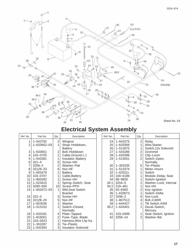
Electrical System AssemblyDescriptionPart No. Qty.Ref. No. DescriptionPart No. Qty.Ref. No.
1 1–543792 2 Wingnut2 1–633652–03 1 Strap–Holddown,
Battery3 1–633651 2 Bolt–Holddown4 103–0705 1 Cable,Ground (–)5 1–543391 1 Insulator–Battery6 321–4 5 Screw–HH7 3256–2 2 Washer–Flat8 32128–33 6 Nut–HF9 1–603479 1 Battery
10 103–0707 1 Cable,Battery11 1–800282 1 Screw–HH12 1–523415 1 Spring–Switch, Seat13 3290–500 10 Screw–PPH14 1–652072–03 1 Wld,Seat Switch
Bracket15 322–3 3 Screw–HH16 32128–20 5 Nut–HF17 1–653036 1 Washer18 1–513152 1 Switch–Closed,
Normally19 1–633181 4 Plate–Tapped20 1–816001 2 Fuse–Type, Blade21 103–0623 1 Harness,Wire Lhp Ka22 1–303287 3 Tie–Plastic23 1–543393 3 Insulator–Solenoid
24 1–643275 2 Relay25 1–633306 1 Wire,Starter26 1–513075 1 Switch,12v Solenoid27 1–543286 2 Grommet28 1–633396 2 Clip–Loom29 1–513051 2 Switch–Open,
Normally30 1–303335 5 Tie–Plastic31 1–513374 1 Meter–Hours32 1–633111 1 Switch33 100–6186 1 Module–Delay, Seat34 88–9830 1 Switch–Ignition
34:1 3254–5 1 Washer–Lock, Internal34:2 218–461 1 Nut–HH
35 63–8360 2 Key–Ignition36 1–633673 1 Switch–Delta37 3296–2 6 Nut–Lock38 1–807513 4 Bolt–CARR39 1–644427 1 Tilt Switch ASM
39:2 1–643401 1 Decal–Switch,Mercury
41 103–0499 1 Seal–Switch, Ignition42 3256–14 2 Washer–flat
3324–974
18
Cylinder/Crankcase Assembly Kawasaki FH601V–S07
3324–974
19
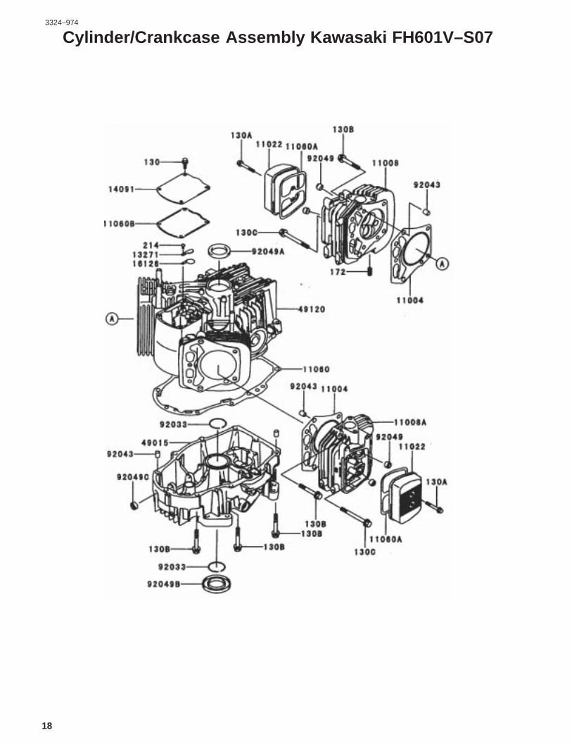
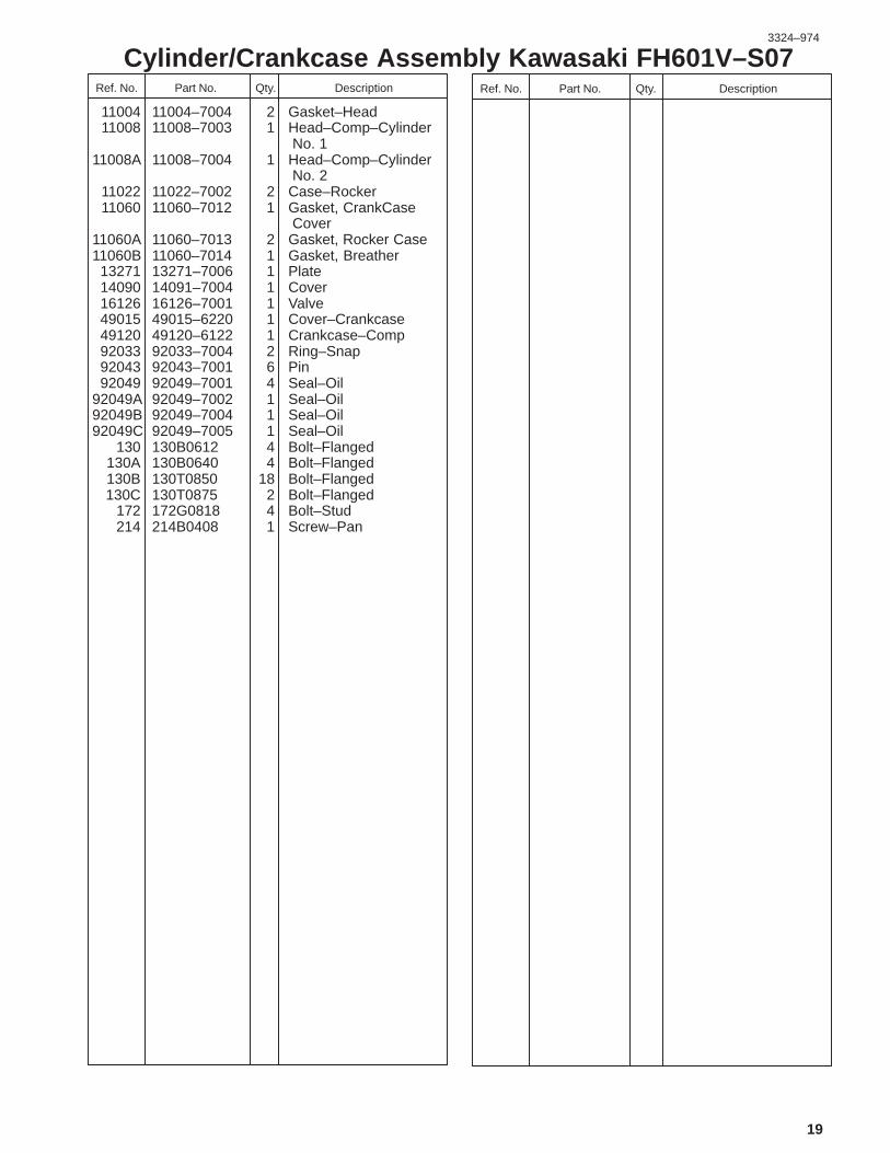
Cylinder/Crankcase Assembly Kawasaki FH601V–S07DescriptionPart No. Qty.Ref. No. DescriptionPart No. Qty.Ref. No.
11004 11004–7004 2 Gasket–Head11008 11008–7003 1 Head–Comp–Cylinder
No. 111008A 11008–7004 1 Head–Comp–Cylinder
No. 211022 11022–7002 2 Case–Rocker11060 11060–7012 1 Gasket, CrankCase
Cover11060A 11060–7013 2 Gasket, Rocker Case11060B 11060–7014 1 Gasket, Breather13271 13271–7006 1 Plate14090 14091–7004 1 Cover16126 16126–7001 1 Valve49015 49015–6220 1 Cover–Crankcase49120 49120–6122 1 Crankcase–Comp92033 92033–7004 2 Ring–Snap92043 92043–7001 6 Pin92049 92049–7001 4 Seal–Oil
92049A 92049–7002 1 Seal–Oil92049B 92049–7004 1 Seal–Oil92049C 92049–7005 1 Seal–Oil
130 130B0612 4 Bolt–Flanged130A 130B0640 4 Bolt–Flanged130B 130T0850 18 Bolt–Flanged130C 130T0875 2 Bolt–Flanged
172 172G0818 4 Bolt–Stud214 214B0408 1 Screw–Pan
3324–974
20
Valve/Camshaft Assembly Kawasaki FH601V–S07

3324–974
21
Valve/Camshaft Assembly Kawasaki FH601V–S07DescriptionPart No. Qty.Ref. No. DescriptionPart No. Qty.Ref. No.
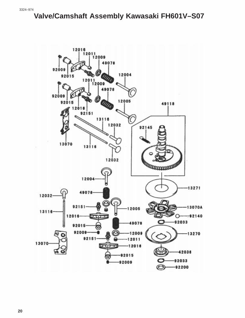
12004 12004–7002 2 Valve–Intake12005 12005–7002 2 Valve–Exhaust12009 12009–7001 4 Retainer–Valve Spring12011 12011–2056 8 Collet12016 12016–7002 4 Arm–Rocker12032 12032–7001 4 Tappet13070 13070–7003 2 Guide
13070A 13070–7004 1 Guide13116 13116–7001 4 Rod–Push13270 13270–7002 1 Plate13271 13271–7007 1 Plate42036 42036–7001 1 Sleeve49078 49078–7002 4 Spring–Engine Valve49118 49118–7003 1 Camshaft–Comp92009 92009–2341 4 Screw92015 92015–2253 4 Nut92033 92033–7001 2 Ring–Snap92140 92140–7002 6 Ball92145 92145–7001 1 Spring92151 92151–7001 4 Bolt92200 92200–7001 1 Washer
3324–974
22
Cooling–Equipment Assembly Kawasaki FH601V–S07

3324–974
23
Cooling–Equipment Assembly Kawasaki FH601V–S07DescriptionPart No. Qty.Ref. No. DescriptionPart No. Qty.Ref. No.
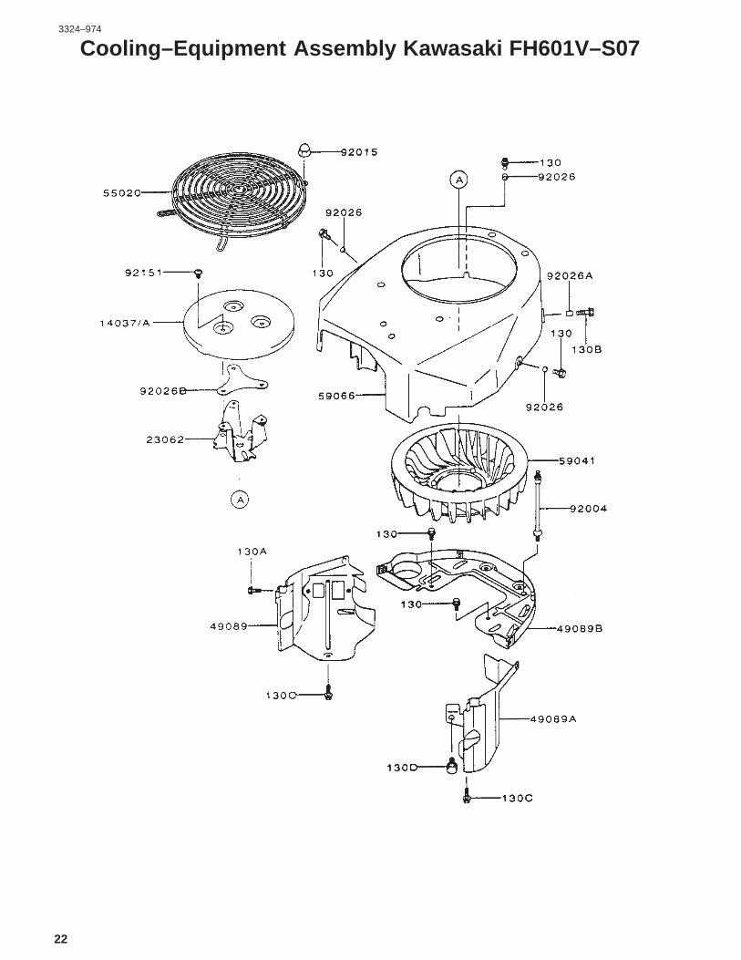
13270 13270–7007 1 Plate14037 14037–7008–9H 1 Screen14091 14091–7002 1 Cover23062 23062–7005 1 Bracket–Comp49089 49089–7004 1 Shroud–Engine
49089A 49089–7005 1 Shroud–Engine49089B 49089–7006 1 Shroud–Engine55020 55020–7002 1 Guard59041 59041–7003 1 Fan59066 59066–7004 1 Housing–Fan92004 92004–2148 2 Stud92015 92015–1170 4 Nut92026 92026–7001 3 Spacer, 6.2x7.9x5
92026A 92026–7003 1 Spacer, 6.5x7.9x10.592026B 92026–7007 1 Spacer92151 92151–7009 3 Bolt, 6x10
130 130B0612 5 Bolt–Flanged130A 130B0620 2 Bolt–Flanged130B 130B0816 1 Bolt–Flanged

3324–974
24
Electric–Equipment Assembly Kawasaki FH601V–S07

3324–974
25
Electric–Equipment Assembly Kawasaki FH601V–S07DescriptionPart No. Qty.Ref. No. DescriptionPart No. Qty.Ref. No.
21066 21066–7003 1 Regulator–Voltage21171 21171–7001 2 Coil–Assy–Ignition21193 21193–7002 1 Flywheel–Assy26011 26011–7008 1 Wire–Lead26030 26030–7002 1 Harness27010 27010–7001 1 Switch59031 59031–7001 1 Coil–Charging92004 92004–2147 2 Stud92009 92009–2308 1 Screw92070 92070–2088 2 Plug–Spark,BPR5ES 92072 92072–7003 2 Band92151 92151–2097 1 Bolt, 12x3092220 92220–7002 1 Washer
130 130B0620 1 Bolt–Flanged224 224B0520 4 Screw–Pan–WP–Cros510 510A5100 1 Key–Woodruff

3324–974
26
Control–Equipment Assembly Kawasaki FH601V–S07

3324–974
27
Control–Equipment Assembly Kawasaki FH601V–S07DescriptionPart No. Qty.Ref. No. DescriptionPart No. Qty.Ref. No.
13107 13107–7004 1 Shaft13270 13270–7006 1 Plate16169 16169–7003 1 Link–Choke16171 16171–7004 1 Link39129 39129–7004 1 Spring–Governor49103 49103–7001 1 Arm–Governor49113 49113–7007 1 Panel–Comp–Control92145 92145–7005 1 Spring
92145A 92145–7009 1 Spring92150 92150–2182 2 Bolt, 5x1892151 92151–7006 1 Bolt, 6x30
92151A 92151–7014 1 Bolt, 5x3092170 92170–7001 2 Clamp
130 130B0612 2 Bolt–Flanged214 214B0408 2 Screw–Pan
214A 214B0412 1 Screw–Pan311 311B0600 1 Nut–Hex411 411B0600 1 Washer–Plain

3324–974
28
Carburetor Assembly Kawasaki FH601V–S07

3324–974
29
Carburetor Assembly Kawasaki FH601V–S07DescriptionPart No. Qty.Ref. No. DescriptionPart No. Qty.Ref. No.
11060 11060–7009 1 Gasket, Air Filter11060A 11060–7010 2 Gasket, Carburetor11060B 11060–7011 2 Gasket11060C 11060–7018 1 Gasket, Float Chamber11060D 11060–7019 2 Gasket, Main Plug11060E 11060–7020 1 Gasket, Solenoid15003 15003–7001 1 Carburetor–Assy16025 16025–7001 2 Valve–Throttle16030 16030–7002 1 Valve–Float16031 16031–7001 1 Float16041 16041–7001 1 Shaft–Carburetor,
Choke16041A 16041–7002 1 Shaft–Carburetor
Throttle16073 16073–7003 1 Insulator16126 16126–7004 1 Valve, Choke16158 16158–7002 2 Jet–Slow, #6016184 16184–7001 1 Chamber–Assy–Float16187 16187–7002 2 Needle–Jet21188 21188–7001 1 Solenoid59076 59076–7002 1 Manifold–Intake92009 92009–7003 6 Screw
92009A 92009–7004 1 Screw92009B 92009–7005 4 Screw92009C 92009–7006 1 Screw, Drain92043 92043–7004 1 Pin–Float92063 92063–7001 1 Jet–Main, #104
92063A 92063–7002 1 Jet–Main, #10692066 92066–7008 2 Plug, Main Jet
92066A 92066–7009 2 Plug, Extension92093 92093–7001 1 Seal
92093A 92093–7002 2 Seal92145 92145–7010 1 Spring
92145A 92145–7011 1 Spring92152 92152–7001 1 Collar92171 92171–7001 1 Clamp92191 92191–7010 1 Tube
130 130B0620 4 Bolt–Flanged172 172G0105 2 Bolt–Stud

3324–974
30
Piston/Crankshaft Assembly Kawasaki FH601V–S07DescriptionPart No. Qty.Ref. No. DescriptionPart No. Qty.Ref. No.
13001 13001–7006 2 Piston–Engine13002 13002–7001 2 Pin–Piston13008 13008–6058 2 Ring–Set–Piston13031 13031–7002 1 Crankshaft–Comp13251 13251–7002 2 Rod–Assy–Connecting92002 92002–2053 4 Bolt92033 92033–7005 4 Ring–Snap

3324–974
31
Lubrication–Equipment Assembly Kawasaki FH601V–S07DescriptionPart No. Qty.Ref. No. DescriptionPart No. Qty.Ref. No.
13107 13107–2099 1 Shaft, Oil Pump13271 13271–7005 1 Plate14075 14075–7002 1 Cap–Assy16154 16154–2053 1 Rotor–Pump, In
16154A 16154–2054 1 Rotor–Pump, Out49065 49065–2078 1 Filter–Oil
49065A 49065–7003 1 Filter–Oil59051 59051–7004 1 Gear–Spur59071 59071–7003 1 Joint59231 59231–7002 1 Filler92043 92043–7003 1 Pin92066 92066–7003 2 Plug92140 92140–7003 1 Ball92145 92145–7002 1 Spring
130 130B0612 3 Bolt–Flanged670 670D2016 4 O–Ring

3324–974
32
Air–Filter/Muffler Assembly Kawasaki FH601V–S07DescriptionPart No. Qty.Ref. No. DescriptionPart No. Qty.Ref. No.
11011 11011–7003 1 Case–Air Filter11013 11013–7009 1 Element–Air Filter
11013A 11013–7010 1 Element–Air Filter11029 11029–7002 1 Element–Assy–Air
Filter11051 11051–7002–9H 1 Bracket11060 11060–7016 2 Gasket, Muffler13271 13271–7008–9X 1 Plate
13271A 13271–7009–9X 1 Plate16060 16060–7001 1 Pipe–Intake18049 18049–7003 1 Pipe–Exhaust42036 42036–7002 1 Sleeve49070 49070–7004 1 Muffler–Comp92015 92015–1193 2 Nut92037 92037–2079 2 Clamp92072 92072–7005 1 Band92171 92171–7002 1 Clamp92191 92191–7006 1 Tube92210 92210–7004 2 Nut
92210A 92210–7008 2 Nut130 130B06105 2 Bolt–Flanged
130A 130B0816 3 Bolt–Flanged172 172G0690 2 Bolt–Stud233 233B0416 1 Screw–Pan–WP311 311B0400 1 Nut–Hex317 317R0800 4 Nut–Hex–Small
411 411B0600 1 Washer–Plain461 461F0800 4 Washer–Spring

3324–974
33
Fuel–Tank/Fuel–Valve Assembly Kawasaki FH601V–S07DescriptionPart No. Qty.Ref. No. DescriptionPart No. Qty.Ref. No.
23062 23062–7004–9H 1 Bracket–Comp49019 49019–7001 1 Filter–Fuel49040 49040–2075 1 Pump–Fuel92170 92170–2088 4 Clamp
92170A 92170–7003 1 Clamp92191 92191–7003 1 Tube
92191A 92191–7005 1 Tube,6.35x12.7x16092191B 92191–7007 1 Tube
130 130B0616 2 Bolt–Flanged130A 130B0620 2 Bolt–Flanged

3324–974
34
Starter/Decals – Kawasaki FH601V–S07DescriptionPart No. Qty.Ref. No. DescriptionPart No. Qty.Ref. No.
13101 13101–7001 1 Gear–Assy21039 21039–7001 1 Brush21080 21080–7001 1 Armature21163 21163–7001 1 Starter–Electric39184 39184–7001 1 Bracket–Assy92151 92151–7013 1 Bolt
130 130B0816 1 Bolt–Flanged56033 56033–7001 1 Decal–Manual56080 56080–7006 1 Decal–Brand
35
Maintenance Record
Date
