for underwater operation...7 hammer modifications early model hammers older model hammers, per...
TRANSCRIPT
INSTRUCTION MANUAL FOR UNDERWATER OPERATION
FOR HYDRAULIC HAMMER MODELS: H8XA, H10XB, H12X, H16X, H20X, H30X
7550 Independence Drive Walton Hills, OH 44146-5541
Phone (440) 232-7900 Toll-free (800) 225-4379
Fax (440) 232-6294
© Copyright 2017 NPK Construction Equipment, Inc. www.npkce.com H035-9611E H8XA - H30X UWTR Instruction Manual 8-17
“Use Genuine NPK Parts”

1
SAFETY Safety notices in the NPK Instruction Manuals follow ISO and ANSI standards for safety warnings:
DANGER (red) notices indicate an imminently hazardous situation which, if not avoided, will result in death or serious injury.
WARNING (orange) notices indicate a potentially hazardous situation which, if not avoided, could result in death or serious injury.
CAUTION (yellow) notices indicate a potentially hazardous situation, which, if not avoided, may result in minor or moderate injury.
ATTENTION (blue) notices in NPK Instruction Manuals are an NPK standard to alert the reader to situations which, if not avoided, could result in equipment damage.
WARNING and BASIC OPERATING INSTRUCTIONS decals are included with each NPK hammer and installation kit. Decals must be installed in the cab, visible to the operator while operating the hammer. STAY CLEAR, PRESSURE VESSEL, GAS PRESSURE and TOOL SHARPENING decals are installed on all NPK hammer models. Keep them clean and visible. NPK will provide decals free of charge as needed.
1. Operator and Service personnel must read and understand the NPK
INSTRUCTION MANUAL to prevent serious or fatal injury. 2. FLYING DEBRIS CAN CAUSE SERIOUS OR
FATAL INJURY.
Keep personnel and bystanders clear of the hammer while in operation.
Do not operate HAMMER without an impact resistant guard between the HAMMER and
operator. NPK recommends LEXAN or equivalent material, or steel mesh. Some carrier manufacturers offer demolition guards for their machine. Check with the carrier manufacturer for availability. If not available, please call NPK.
3. Do not hardface or sharpen the tool point with a cutting torch. Excessive heat from torching or welding can cause embrittlement, breakage, and flying pieces. Resharpen by milling or grinding only, using sufficient coolant.

2
SAFETY
4. Fully extend the tool while charging the HAMMER with nitrogen gas. Be sure that the retaining pin is installed. STAY CLEAR OF TOOL POINT WHILE CHARGING.
5. Do not disassemble a HAMMER before discharging the hammer gas pre-charge. 6. USE NITROGEN GAS ONLY! Store and handle nitrogen tanks per OSHA
regulations. 7. Avoid high pressure fluids. Escaping fluid under pressure can penetrate
the skin causing serious injury. Relieve pressure before disconnecting hydraulic or other lines.
8. Operate HAMMER from operator’s seat only. 9. Match HAMMER size to carrier according to NPK recommendations. The carrier
must be stable during hammer operation and during transport. 10. Do not make any alterations to the TOOL without authorization from NPK
Engineering. 11. Use proper lifting equipment and tools when handling or servicing the
HAMMER. 12. Wear ear protection if conditions warrant. Consult OSHA regulations. 13. Wear safety glasses at all times. Beware of flying debris. 14. If modifications are to be made, do not alter the HAMMER without
authorization from NPK Engineering! 15. Use only genuine NPK replacement parts. NPK specifically disclaims any
responsibility for any damage or injury that results from the use of any tool or parts not sold or approved by NPK.
For further safety information, consult the AEM Hydraulic Mounted Breakers Safety Manual, AEM form MB-140 (NPK P/N H050-9600), which is furnished with every NPK hammer. To request an additional copy, please contact NPK at 1-800-225-4379 or Internet at www.npkce.com.

CONTENTS
3
SAFETY .................................................................................................................. 1 FORWARD ............................................................................................................. 4
OPERATING PRINCIPLE ....................................................................................... 4 AIR SUPPLY ........................................................................................................... 5
Air Compressor ................................................................................................... 5 Air Pressure ........................................................................................................ 5
NPK UNDERWATER KIT LISTING ........................................................................ 6 HAMMER MODIFICATIONS................................................................................... 7
Early Model Hammers ......................................................................................... 7 Late Model Hammers .......................................................................................... 9
HAMMER OPERATION .......................................................................................... 11 Before Start-Up ................................................................................................... 11
Setting the Air Pressure ...................................................................................... 11 CARE AFTER USE ................................................................................................. 12
WARRANTY STATEMENTS .................................................................................. 13

4
FORWARD The NPK HYDRAULIC HAMMER is a rugged boom mounted demolition tool that can be operated underwater by making certain modifications and following the procedures in this manual. Read and understand the SAFETY INFORMATION and operating instructions in the NPK OPERATORS MANUAL before operating the hammer. If there are any questions, call the NPK Service Department at 1-800-225-4379.
OPERATING PRINCIPLE Although the hydraulic oil section of the hydraulic hammer is sealed completely, water can enter into the area where the piston (N) impacts the tool (HH) when the hammer is used underwater. The hammer must be modified for underwater operation. If not, water (107) trapped in the striking chamber (172) will be forced against the piston seals (PP) as the piston strokes (106) down to impact the tool. The water pressure is extremely high and greater than the seals can withstand. The seals are distorted out of their grooves. This causes the piston to be forced against the sleeve (P). This, in turn, can damage the piston and both sleeves. The water forced past the seals enters the carrier hydraulic system (171) and can damage pumps and other components. To keep water from entering the striking chamber of the hammer when submersed, the hammer must be supplied with compressed air (see the following pages for air compressor size and connections required).

5
AIR SUPPLY
Air Compressor The air compressor capacity varies with the hammer size. The base underwater kit is designed so that compressed air is supplied to the striking chamber area during operation. The addition of a portable air compressor capable of 100 cfm constant and a air flow regulator are required.
HAMMER COMPRESSOR
MODEL CAPACITY
H8XA 30 CFM (minimum)
H10XB
H12X 40 CFM (minimum)
H16X
H20X 50 CFM (minimum)
H30X 60 CFM (minimum)
Air Pressure The air pressure setting is dependent on the working depth of the hammer. The air line will require a pressure regulator to reduce the pressure. See the operating section of this manual for the pressure setting procedure.
6
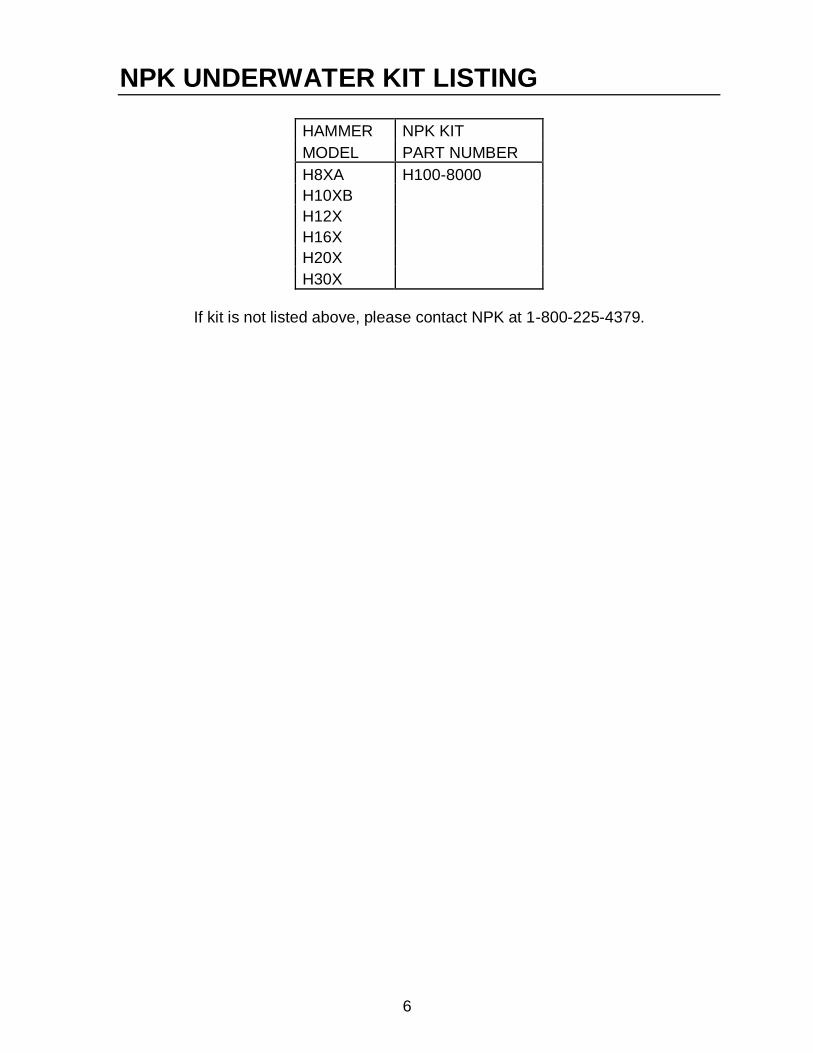
NPK UNDERWATER KIT LISTING
HAMMER NPK KIT
MODEL PART NUMBER
H8XA H100-8000
H10XB
H12X
H16X
H20X
H30X
If kit is not listed above, please contact NPK at 1-800-225-4379.

7
HAMMER MODIFICATIONS Early Model Hammers Older model hammers, per serial number list below, need no disassembly of the hammer for underwater operation. However, if the hammer has been retrofitted for auto lube operation, disassembly is necessary (see modifications for “LATE MODEL HAMMERS”).
HAMMER SERIAL
MODEL NUMBER
H8XA BELOW s/n 44486
H10XB BELOW s/n 44355
H12X BELOW s/n 41369
H16X BELOW s/n 41040
H20X ALL s/n
H30X BELOW s/n 41060
PROCEDURE
1. Remove the exhaust valve poppet and spring assembly (uw1) from the hammer
main body. Install adapter fitting (DQ), NPK part number 11024312, which has a 1/2” female npt port for the air hose connection. Install a heavy duty elbow fitting (CF) to connect to the air hose (uw2).

8
HAMMER MODIFICATIONS Early Model Hammers PROCEDURE
2. Replace the existing retaining pin with a new pin assembly made for underwater operation. Contact the NPK Service Department for assistance if part numbers are not listed below.
HAMMER PIN RETAINING COLLAR HEX HEAD HEX
MODEL KIT PIN (D) (AT) CAP SCREW NUT (CI)
(AF)
H8XA ** ** ** ** **
H10XB H290-8050 H290-1085 H290-1086 K036-4500 K036-4510
H12X ** ** ** ** **
H16X H351-8050 H351-1080 H351-1081 K050-4500 K036-4510
H20X ** ** ** ** **
H30X ** ** ** ** **
** Part numbers available upon request.
3. Remove the drain plug (B) from the hammer body (located above the main valve assembly) and replace with a solid 1/4" npt plug (AS1), NPK part number K023-6660.
4. Attach the air line from the air compressor to the adapter fitting on the hammer.
Hoses must be secured and protected from damage during operation.

9
HAMMER MODIFICATIONS Late Model Hammers Late model hammers, per serial number list below, as shipped from NPK are configured for auto lube operation, which is not compatible with underwater operation.
HAMMER SERIAL
MODEL NUMBER
H8XA STARTING at s/n 44486
H10XB STARTING at s/n 44355
H12X STARTING at s/n 41369
H16X STARTING at s/n 41040
H20X N/A
H30X STARTING at s/n 41060
PROCEDURE 1. For underwater operation, the impact ring must be disassembled and rotated
180°, per drawing below. The impact ring (J1) final position will have an “EX”
stamp on the valve side face to indicate underwater operation. NOTE: In the auto lube configuration, the impact ring (J2) has an “AL” stamp on
the valve side to indicate auto lube operation. Note position of the lubrication groove (a79).
2. Remove the plug from the adapter fitting (DQ) which has a 1/2" female npt port
for the air hose connection. Install a heavy duty elbow fitting (CF) to connect to the air hose (uw2).

10
HAMMER MODIFICATIONS Late Model Hammers 3. Replace the existing retaining pin (D) with a new pin assembly made for
underwater operation. Contact the NPK Service Department for assistance if part numbers are not listed below.
HAMMER PIN RETAINING COLLAR HEX HEAD HEX
MODEL KIT PIN (D) (AT) CAP SCREW NUT (CI)
(AF)
H8XA ** ** ** ** **
H10XB H290-8050 H290-1085 H290-1086 K036-4500 K036-4510
H12X ** ** ** ** **
H16X H351-8050 H351-1080 H351-1081 K050-4500 K036-4510
H20X ** ** ** ** **
H30X ** ** ** ** **
** Part numbers available upon request.
4. Remove the drain plug (B) from the hammer body (located above the main valve
assembly) and replace with a solid 1/4” npt plug (AS1), NPK part number K023-6660.
5. Attach the air line from the air compressor to the adapter fitting on the hammer.
Hoses must be secured and protected from damage during operation.

11
HAMMER OPERATION
When used in water, any hammer is subjected to much more severe conditions than when used on land. Therefore, the hammer must be handled more carefully. 1. Never operate the hammer without air supply! 2. Never start to operate the hammer before the compressor tank pressure reaches
85 PSI. 3. If the air supply is stopped during operation, stop operation immediately and
determine the cause. 4. If the carrier is on board a barge, the tool is more liable to break because the
force of the carrier and the sway of the barge from wave action will act together on the tool.
5. Grease is blown off by supplied air. Grease the hammer generously and more often than when used on land. If the unit is equipped with a auto lube, it is still recommended that the hammer is greased manually every hour.
Before Start-Up Grease the hammer per the instructions in the NPK HYDRAULIC HAMMER SERVICE MANUAL.
Setting the Air Pressure 1. Start the compressor to supply air to the hammer before it is submerged in the
water. 2. Extend the carrier boom down to the maximum working depth used on the job
site and keep the hammer submerged in the water. Bubbles will be generated from the tool area due to air supply.
3. While maintaining the above condition, reduce the air pressure gradually with the pressure regulator, and set the supplied air pressure at the minimum level required to produce bubbles.
1. Reduce the pressure of the compressed air with the regulator as instructed
above. Do not supply unregulated high pressure compressed air (85 PSI) from the compressor directly to the hammer. Excessive air pressure may be forced into the hammer through the sealed area.
2. A compressor with higher capacity than shown in the table, see page 5, can be used, but be sure to control the pressure as described above because the volume of compressed air supplied is greater.

12
CARE AFTER USE Because the hammer is used in water, it is susceptible to rust and corrosion. Use due care when draining the water. 1. When the hammer is used every day:
a. Operate the hammer out of the water for several minutes, while supplying air, to drain the water completely.
b. If it is difficult to operate the hammer out of water, run the engine at low RPM and idle the hammer 5 to 6 times while maintaining air supply.
2. When the hammer is not used for a long period of time (longer than 30 days):
a. After completing the procedures described above, position the hammer as illustrated below and discharge the nitrogen gas inside the head cap completely, using the NPK charge adapter.
b. While keeping the charge valve in an OPEN state, run the engine at a low speed and actuate the hammer foot switch for 2 to 3 seconds.
c. Remove the charge adapter. d. Pour approximately one quart of oil (t52) into the lower end of the tool
holder. e. Cover the tool end of the hammer to prevent water or moisture from
entering the tool holder.

13
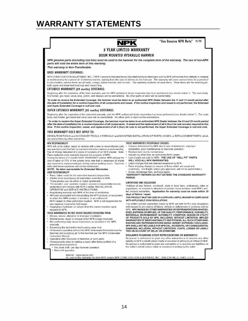
WARRANTY STATEMENTS
14
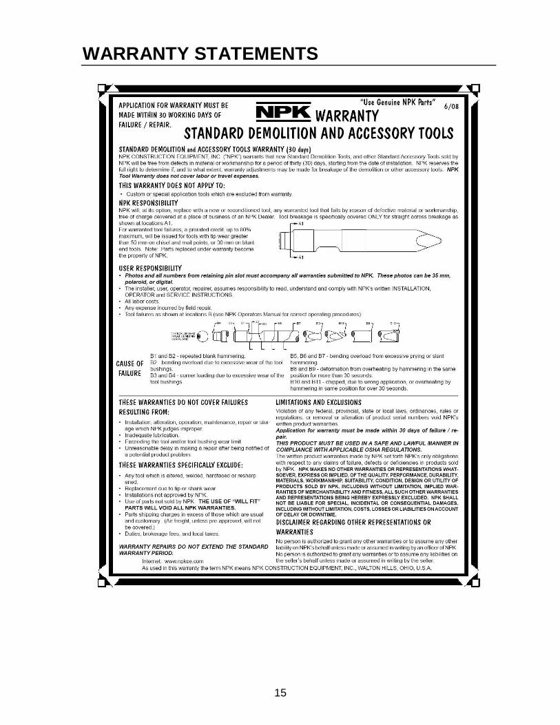
WARRANTY STATEMENTS
15
WARRANTY STATEMENTS

16
WARRANTY STATEMENTS

17
WARRANTY STATEMENTS

© Copyright 2017 NPK Construction Equipment, Inc. www.npkce.com H035-9611E H8XA - H30X UWTR Instruction Manual 8-17