for tollway transportation structures and facilities - inti · tollway transportation structures...
TRANSCRIPT

DESIGN MANUAL
For
Tollway Transportation Structures and Facilities
January 2008
ILLINOIS STATE TOLL HIGHWAY AUTHORITY

The Design Manual for Tollway Transportation Structures dated January 2008 replaces the previous version dated June 2000. The Manual has been revised to reflect the most recent changes in the IDOT Manual and Specifications including the latest Tollway Supplemental Specifications to IDOT Standard Specifications. The Manual mandates the use of the AASHTO LRFD Specification for new and replacement bridges designed after January 2008. The following sections have been added. Section 1 Introduction Section 3 Type, Size & Location (TS&L) Plans Section 4 Context Sensitive Solutions Section 24 Overhead Sign Supports Section 26 Rehabilitation and Repair Many other sections have undergone extensive revisions. The Manual includes a subsection on guidelines for the use and design of splice PPC Bulb Tee Girders. Also, the sleeper slab detail for approach slabs has changed from grade beam supported by compacted fill to pile bent cap.
January 2008 Illinois Tollway

DESIGN MANUAL FOR TOLLWAY TRANSPORTATION STRUCTURES
TABLE OF CONTENTS
SECTION 1.0 INTRODUCTION
SECTION 2.0 STRUCTURE INSPECTION AND CONDITION REPORTS
SECTION 3.0 TYPE, SIZE & LOCATION (TS & L) PLANS
SECTION 4.0 CONTEXT SENSITIVE SOLUTIONS
SECTION 5.0 GENERAL
SECTION 6.0 GENERAL PLAN AND ELEVATION
SECTION 7.0 GENERAL NOTES, INDEX OF DRAWINGS AND TOTAL BILL OF MATERIAL
SECTION 8.0 CONSTRUCTION STAGING
SECTION 9.0 SUBSTRUCTURE AND SHEET PILING LAYOUTS
SECTION 10.0 ABUTMENTS
SECTION 11.0 PIERS
SECTION 12.0 STRUCTURAL STEEL
SECTION 13.0 PRECAST PRESTRESSED CONCRETE (PPC)
SECTION 14.0 BEARINGS
SECTION 15.0 CONCRETE BRIDGE DECKS AND BARRIERS
SECTION 16.0 DECK DRAINAGE
SECTION 17.0 BRIDGE DECK EXPANSION JOINTS
SECTION 18.0 DECK ELEVATIONS
SECTION 19.0 APPROACH PAVEMENT (SLABS)
SECTION 20.0 SOIL BORING LOGS
SECTION 21.0 CULVERTS
January 2008 i Illinois Tollway

DESIGN MANUAL FOR TOLLWAY TRANSPORTATION STRUCTURES
TABLE OF CONTENTS
SECTION 22.0 RETAINING WALLS
SECTION 23.0 NOISE ABATEMENT WALLS
SECTION 24.0 OVERHEAD SIGN SUPPORTS
SECTION 25.0 SHOP DRAWINGS
SECTION 26.0 REHABILITATION AND REPAIR
January 2008 ii Illinois Tollway

SECTION 1.0 INTRODUCTION
1.1 LRFD and LFD Bridge and Structure Design
The Illinois State Toll Highway Authority (Tollway) is currently transitioning from the American Association of State Highway and Transportation Officials (AASHTO) “Standard Specifications for Highway Bridges – Division I” Load Factor Design (LFD) and Allowable Stress Design (ASD) to the AASHTO Bridge Design Specifications Load and Resistance Factor Design (LRFD) for new bridge construction. It is anticipated that this process will be ongoing over the next few years. As such, this Design Manual pertains to both the AASHTO Standard and LRFD Specifications.
The design of all new and replacement structures after November of 2007 shall be in accordance with the latest edition of the AASHTO “LRFD Bridge Design Specifications” except as modified by the following Illinois Department of Transportation (IDOT) Manuals: Bridge, Prestressed Concrete, Culvert, Drainage, Geotechnical and Sign Structures, or as amended herein by the Tollway “Design Manual for Tollway Transportation Structures and Facilities”.
The AASHTO LRFD Bridge Design Specifications was not completely adopted by IDOT. Several parts were modified or subjected to interpretation by IDOT. The following examples are representative of some of the changes made by IDOT:
• Retaining wall (IDOT Bridge Manual, Section 3.11) and culvert design will only be according to the AASHTO Standard Specifications (Section 2.1.2).
• Portions of Live Load Distribution for bridges have been simplified and/or not adopted (Section 3.3.1).
• Vehicle collision design forces and the approach to design have been interpreted by IDOT (Section 3.9.3.7).
• Moment Redistribution in LRFD and LFD is not allowed (Section 3.3.6).
• When to apply lateral stresses for steel beam design has been interpreted (Section 3.3.5).
• The loading to use for Constructability Checks in LRFD (and LFD) has been clearly specified and interpreted (Section 3.3.26).
• The phi factor to use for pile design has been interpreted (Section 3.10).
• Seismic design is according to LRFD with some interpretations, but the Bridge Manual makes clear which options in LRFD to use for Illinois (Sections 3.7, 3.10 and 3.15).
January 2008 1-1 Illinois Tollway

Existing structures which are to be rehabilitated, reconstructed and/or widened will be designed in accordance with the appropriate Division I or IA (LFD or ASD) of the latest AASHTO “Standard Specifications for Highway Bridges”. All other structures shall be designed by the specification indicated in the following “Structural Design Specifications Selection Table.”
Structural Design Specification Selection Table New or Replacement Projects:
Bridges AASHTO LRFD Bridge Design Spec. PPC Beams and CIP Concrete Culverts
AASHTO Standard Spec. for Highway Bridges Division I (LFD)
Retaining Walls, Sound Walls and Sign Structures
AASHTO Standard Spec. for Highway Bridges Division IA (ASD)
Rehabilitation Projects: For existing ASD or LFD Designs AASHTO Standard Spec. for Highway Bridges For existing LRFD Designs AASHTO LRFD Bridge Design Spec. Ratings: For Existing ASD or LFD Designs AASHTO Manual for Condition Evaluation of
Bridges For New and Existing LRFD Designs
AASHTO Guide Manual for Condition Evaluation and Load and Resistance Factor Rating (LRFR)
1.2 Seismic Design of Bridges
Tollway structures shall be designed to meet the minimum requirements for AASHTO Seismic Performance Zone 1 (LRFD) or Category A (LFD) with a low probability of being exceeded during the normal life expectancy for a bridge. Bridges and their components that are designed to resist Zone 1 (Category A) forces and constructed in accordance with the design details contained in this manual should not experience total collapse, but may sustain repairable damage due to seismically induced ground shaking.
1.3 Manual Updates
The “Design Manual for Tollway Structures and Facilities” will be continually reviewed by the Tollway. Updates to the manuals will be issued as frequently as needed. The most current IDOT manuals and Tollway Design Manual related to bridge policy, documents and procedures are available on the Internet web pages at the following sites:
http://www.dot.il.us/bridges/brdocuments.html
http://www.illinoistollway.com
1.4 Design Section Engineers (DSE) Manual
For a complete list of Tollway terms, definitions and acronyms including project requirements, see the latest DSE Manual.
January 2008 1-2 Illinois Tollway

SECTION 2.0 STRUCTURE INSPECTION AND CONDITION REPORTS
2.1 Inspection and Testing
Inspection of existing bridges, culverts, and retaining walls shall be conducted in accordance with the latest, Federal Highway Administration (FHWA) “Manual for Bridge Inspectors” and its supplement “Inspection of Fracture Critical Bridge Members,” and the AASHTO “Manual for the Condition Evaluation of Bridges.” Underwater inspections and evaluations when required shall be conducted according to the latest FHWA Manual for “Underwater Inspection of Bridges.”
2.2 Preparation of Structure Condition Reports
Reports will follow the guidelines of the latest IDOT “Bridge Condition Report Procedures and Practices” except as amended herein the Tollway’s “Guidelines for Bridge Condition Reports (2001)”. Existing structures to be abandoned and/or removed or completely replaced will not be inspected or require a condition report. Only those structures which are to be rehabilitated, reconstructed or widened will require both in-depth inspections and condition reports.
In general, retaining walls will not be inspected or require a condition report, unless the existing wall(s) or portions thereof are to be incorporated into the proposed project. In which case, an inspection shall be performed and a condition report prepared for each wall or section to be utilized in conjunction with the project.
2.3 Hydraulic Analysis
A hydraulic analysis will be required for all bridges and culverts over or conveying water for all new and replacement structures, bridge widenings and culverts.
The results of the analysis will be summarized in a Waterway Information Table which along with the hydraulic report shall be included in the condition report for each structure. The report will also include any recommendations for improving the existing channel alignment and/or waterway opening. The report shall also note any potential conditions that should be further investigated by a scour analysis.
2.4 Scour Analysis
A scour analysis will be required for all new and replacement structures, bridge widenings and culvert extensions over or conveying water.
Scour will be evaluated for the existing or proposed site conditions.
2.5 Live Cycle Cost Analysis
Live Cycle Cost Analysis is required on all replacement verses rehabilitation decisions in accordance with the “Policy of Live Cycle Cost Analysis for The South Tri-State Tollway (April 2002)”.
January 2008 2-1 Illinois Tollway

SECTION 3.0 TYPE, SIZE & LOCATION (TS & L) PLANS
3.1 General
The TS & L plan forms the basis for preparation of Contract Plans which are used to construct the structure. TS & L plans will be required for new or replacement structures, and all structure widenings and superstructure replacements. Structures scheduled for rehabilitation and/or redecking will not require TS & L Plans. TS & L Plans for Tollway structures will not require completion of a “Structure Report” or “Project Development Outline”. TS & L Plans for those structures that are either fully or partially maintained by IDOT shall follow all guidelines and requirements of Section 2.0 of the latest IDOT Bridge Manual. Prior to submittal of TS&L Plans the Plans should be checked for compliance with the checklist per IDOT’s Bridge Manual Section 2.3.13.
3.2 Hydraulic Report
TS & L plans for all new and replacement structures, bridge widening and culvert extensions over or conveying water will require a Hydraulic Report and Waterway Information Table including a scour analysis and a Design Scour Elevation Table if necessary.
3.3 Structure Geotechnical Report
TS & L plans for all new and replacement structures, bridge widening and culvert extensions will require a subsurface soil investigation and Structure Geotechnical Report (SGR) with foundation recommendations. The subsurface soil investigation shall be performed in accordance with the latest IDOT and Tollway Geotechnical Manuals.
January 2008 3-1 Illinois Tollway

SECTION 4.0 CONTEXT SENSITIVE SOLUTIONS
4.1 Introduction
Context Sensitive Solutions (CSS) is an interdisciplinary process, embraced by the Illinois Department of Transportation and the Tollway, that seeks effective, multimodal transportation solutions by working with stakeholders to develop, build and maintain cost-effective transportation facilities which fit into and reflect the project’s surrounds – its “context”. Through early, frequent and meaningful communication with stakeholders and a flexible and creative approach to design, the resulting projects improve safety and mobility for the traveling public, while seeking to preserve and enhance the scenic, economic, historic and natural qualities of the settings through which they pass. The Tollway will determine which new construction, reconstruction and major expansion projects will utilize the CSS process.
4.2 Design Guidelines
The CSS process shall be in accordance with the latest edition of the Design Manual for Tollway Transportation Structures and Facilities.
4.3 Bridges
Bridges on the mainline or on crossroads are points where local roadways cross the Tollway. Bridges contribute to the overall image and identity of the Tollway because of their quantity, architectural character and land forms.
The basic treatment for a bridge and the overpass or underpass area is the use of a standard, utilitarian highway bridge, seeding of landscaped areas and standard Tollway signage identifying the crossroad. The upgrade treatment for a bridge and the overpass or underpass area is the addition and enhancement of architectural landscape and signage components, where a response to the significance of the crossroad, physical context, or community is needed.
4.4 Walls
Walls, including sound and retaining walls, are major aesthetic components of the Tollway corridors. Walls should be designed as visual assets to motorists and adjoining communities. Walls provide a CSS opportunity for communities to suggest color, materials and/or graphic enhancement.
January 2008 4-1 Illinois Tollway

SECTION 5.0 GENERAL
5.1 Plan Presentation
Bridge Plans are a means of communication between the Design Section Engineer (DSE) and the Contractor. The plans must be accurate and explicit. During the letting process they will be reduced to approximately one-quarter size (11”x17”), therefore, care must be taken in the organization and presentation of each plan sheet.
To provide the Construction Manager (CM) with some sense of proportioning in the drawing presentation, each view, section, or detail should be drawn, as near as possible, to scale. Even though the drawings will be reduced, it is not necessary to show the scale used under each view, section or detail.
Prior to submittal of the 95% Prefinal plans for the Tollway review, the consultant must ascertain the plans to comply with the checklist per IDOT’s Bridge Manual sheets 3-33 and 3-44 thru 3-53.
Final Plans shall be prepared in accordance with the requirements outlined in the latest edition of the Design Section Engineer's Manual and these design criteria. The DSE shall utilize the “Final Plan Check Sheet” from Subsection 3.1.13 of the latest IDOT Bridge Manual to review the final plans for each structure before they are submitted to the Tollway for review.
5.2 Plan Sheet Organization
Each bridge, culvert and retaining wall shall consist of a set of sequentially numbered plan sheets. Plan sheets shall be organized in such a manner as to facilitate construction. The general plan and elevation will come first, followed by general notes and quantities, substructure layout, pile driving and/or drilled shaft records, substructure, superstructure, approach slabs, and boring logs. Shown below are plan sheet lists for several types of structures.
5.2.1 Bridges 1. General Plan and Elevation 2. General Notes, Index of Sheets and Total Bill of Material 3. Construction Staging 4. Substructure Layout, Temporary Retention and Slope Paving Details 5. Limits and details of Temporary Soil Retention System 6. Pile Driving and/or Drilled Shaft Installation Records 7. Abutment Details 8. Pier Details 9. Framing Details 10. Bearing and Anchor Rod Details 11. Superstructure Elevations 12. Superstructure Details 13. Approach Span Details 14. Expansion Joint Details 15. Drainage Details 16. Approach Slab Details 17. Boring Logs
January 2008 5-1 Illinois Tollway

5.2.2 Culverts
5.2.3
5.3.1 General
1. General Plan and Elevation 2. General Notes, Index of Sheets and Total Bill of Material 3. Construction Staging (if required) 4. Foundation Layout and Details (if required) 5. Limits of Temporary Soil Retention Systems (if required) 6. Barrel Details 7. Head and Wing Wall Details 8. Approach Slab Details (if required) 9. Boring Logs
Retaining Walls 1. General Plan and Elevation 2. General Notes, Index of Sheets and Total Bill of Material 3. Construction Staging (if required) 4. Substructure Layout and Limits of Temporary Soil Retention System (if required) 5. Pile Driving and/or Drilled Shaft Installation Records 6. Detail Plans and Elevations 7. Sections and Details 8. Rebar Lists and Bending Diagrams 9. Drainage Details (if required) 10. Boring Logs
5.3 Plan Preparation
The Tollway has a policy of reducing all plans that are to be let to contract. Because this reduction works both horizontally and vertically, a plan sheet approximately one-fourth (11”x17”) the size of the original plan sheet will result. These quarter-size prints will be the plans from which the contractor figures his bid and constructs the structures in the Contract.
Due to this policy, what is considered as "normal drafting practice" may not apply. It requires a constant awareness on the part of the DSE. The DSE should ask, "How will this appear when it is reduced by one-half both horizontally and vertically?" As to the matter of the vertical reduction, the height of the lettering is affected; spacing between lines of lettering in plan notes and spacing between horizontal lines on the drawing is also affected. In the horizontal reduction, the width of the individual letters is reduced by one-half. Consequently, if lettering is closely spaced on drawings, the sheet is not suitable for reduction. Spacing between two (2) lines drawn close together in the vertical is also reduced by one-half. Take particular care to exaggerate the space between any two (2) lines which would normally be drawn close together on plan sheets, such lines could represent expansion devices and curbs on the deck plan.
Upon completion of construction, the original CAD files will be corrected to reflect as-built conditions. The electronic files become part of the permanent record for each Contract. Prints can be made at any time in the future if it becomes necessary to do additional work on the bridge.
January 2008 5-2 Illinois Tollway

5.3.2 Lettering
5.3.3
5.3.4
5.3.5
5.3.6
5.3.7
5.3.8
All letters and numbers should be made with open noncompressed lettering. All lettering shall be vertical style, upper and lower case lettering. Slanted lettering will be prohibited. See Figure 5.3.2.1 for examples for the size and type of lettering required.
Line Work
The outline of the object should stand out sharply, with reinforcing lines somewhat thinner. Dimension lines, centerlines, cross-hatching, and existing structure lines should be still thinner.
Closely drawn lines should be avoided as they tend to run together to make one (1) heavy line when the drawing is reduced. Some exaggeration of scale may be used in areas where this might occur as in the case of barrier rails (parapets) and expansion joints on the deck plan.
Small scale crowded elevations, views, and sections are not acceptable and while no minimum scale is required, consideration should be given to moving section views to other sheets, separate from plan and elevation with appropriate cross referencing notes. Reinforcing bar lists, bill of materials, and large notes can be placed on separate drawings.
See Figure 5.3.3.1 for recommended line types and thicknesses.
Material Symbols
Bridge structure materials shall be depicted in all sections and details using the symbols shown in Figure 5.3.4.1.
Sheet Numbers
Plan sheets for each bridge structure shall be numbered as shown in Figure 5.3.5.1.
North Arrow
Each plan view shall be accompanied by a North Arrow as shown in Figure 5.3.6.1.
Individual Bills of Material
Each element of the substructure and superstructure including approach slabs shall have a Bill of Material shown on the appropriate plan sheet. See Figure 5.3.7.1 for the Bill of Material format.
Concrete Reinforcement Detailing
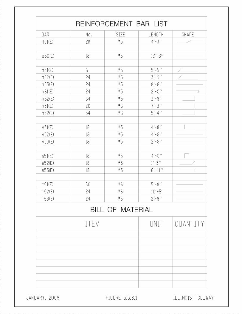
Separate Reinforcing Bar Schedules shall be prepared for each element of the structure and shown along with bending diagrams of each bent bar on the appropriate plan sheet. See Figure 5.3.8.1 for the Reinforcing Bar List format.
January 2008 5-3 Illinois Tollway

When detailing lengths of reinforcement bars, consideration must be given to transportation and handling and, where extremely long lengths are contemplated, to availability and special orders. When the location of bar splices is arbitrary, as in the case of the longitudinal reinforcement of deck slabs on beams and girders, the preferred maximum lengths are as follows:
#6 bars and up...........36'-0" #4 & #5 bars ..............30'-0"
Bars shall be detailed to the closest inch of length and the weight of reinforcement bars shown in the Bill of Material shall be to the nearest ten (10) pounds.
To provide uniformity on all structure plans, bar designations used shall be as follows:
a – Deck Slab (Transverse) b – Deck Slab, Sidewalk and Median (Longitudinal) c – Sidewalk and Median (Transverse) d – Barrier Rail Parapets (Vertical) or Dowels (at any location except Footing to Wall) e – Concrete Barrier Rail Parapets (Longitudinal) g – Concrete Beams h – Substructure (Horizontal) m – Diaphragm for PPC I-Beams (Horizontal) n – Footing to Wall (Dowels) p – Pile Caps and Pier Caps (Longitudinal) s – Stirrup and Tie Bars t – Footing (Transverse) u – Ends of Pier Caps, Pile Caps and Crash Walls v – Substructure (Vertical) w – Footing (Longitudinal) x – Deck Slab – Longitudinal Deck Cantilevers at Expansion Joints
In no case shall the same designation be used for reinforcement bars of a different size, length and shape when they are employed in other elements of the structure.
5.3.9
5.4.1
Dimensioning Accuracy
Dimensioning shown on the plan sheets shall be carried out to the units shown in Figure 5.3.9.1.
5.4 Design Criteria
Design Vertical Clearances
• New Bridges Spanning Interstate, Tollway, Primary Systems, or Major Collectors – 16'-3". 16'-3" allows for an ultimate 16'-0" clearance after a 3" overlay is constructed.
• On bridge widenings, not less than existing.
• On bridge replacements at Tollway Interchanges, not less than the existing or less than 15'-3" (15'-0" permitted to the top of an existing or added overlay). 16'-3" shall be provided when feasible.
• Pedestrian overpass and clearance of 17'-3" is to be provided from roadway to bottom of luminaires whether or not luminaires are required.
January 2008 5-4 Illinois Tollway

• Mainline and Ramp Plaza Canopies – 17'-3".
• I-PASS overhead equipment truss structures – 17'-6"
• Structures over railroads – 23'-0" between top of rail and low structure measured at or within 8'-0" each side of center of outside track. On widening structures, not less than the existing, unless written approval is obtained from the railroad. Any clearance less than 21'-6" will require I.C.C. approval.
• Stream crossings – 2'-0" measured between design high water and low structure or 1'-0" between any measured high water and low structure. Use whichever criteria produces the highest low structure.
• Roadway Design Criteria shall be followed for the Tollway Bridges over crossroads and meet existing or current crossroad agency prescribed minimums, whichever is lower.
5.4.2 Design Horizontal Clearances
Bridge Superstructure:
On the Tollway System minimum bridge widths shall match the approach roadway. Right shoulders – 12'-0" minimum and left shoulders 6'-0" minimum. Increase shoulder widths on long curved bridges, if necessary, to provide required sight distances.
Bridge Substructure:
Edge of pavement to the nearest face of existing piers on the Tollway System shall be 10'-0" minimum. Exceptions may be granted at selected locations where costs of providing the minimum are prohibitive.
Edge of pavement to the nearest face of new piers on the Tollway System shall be 30'-0" unless protected by a barrier or guardrail. The preferable design for a bridge crossing the Tollway is a 2-span continuous structure without shoulder piers.
At closed abutments, the clearance between the edge of mainline pavement to face of new abutment on the Tollway System shall be 30'-0 unless protected by barrier or guardrail. At integral and vaulted abutments, the clearance between the edge of mainline pavement to the toe of the 2:1 slope shall be 30'-0" unless protected by barrier or guardrail. See Figure 5.4.2.1.
5.4.3
5.5.1 General
Minimum Number of Beam Lines
It is the Tollway preference to have minimum of six beam lines on all bridge projects including the Ramps.
5.5 Field Survey
Prior to the beginning of the conceptual or TS&L designs, a field survey shall be completed and shall include, but shall not be limited to, the items as outlined herein. A stationing system shall be established and all topography within the site which is relevant to the proposed work shall be
January 2008 5-5 Illinois Tollway

collected utilizing one of the networks of Continuously Operating Reference Stations (CORS) coordinated by the National Geodetic Survey (NGS). Tollway CORS stations are located at the following Maintenance and or Plaza facilities:
Station Name Station I.D. Number ALSIP TM01 GURNEE TMO4 SCHAUMBURG TMO5 BELVIDERE TM06 ROCKFORD TMO7 NAPERVILLE TM08 DEKALB TM11 DIXON TM12 BOLINGBROOK TP89
A permanent Benchmark for each structure shall be established and all elevations taken for the structure shall be tied to this Benchmark.
5.5.2
5.5.3 Bearings
5.5.4
Modified Barrier Rails (Parapets)
On existing barriers, which are proposed for modification, the joint locations shall be field verified before designing the new longitudinal reinforcing bars.
A condition survey shall be made of the bridge bearings to verify the recommendations made in the Bridge Condition Report. On bearings proposed for replacement, measurements between the bottom of the girder and the top of the bearing seat shall be taken at all four corners of existing bearings to determine if shims are required.
Bridge Deck Widening
On bridges which are to be widened, the following data shall be obtained or verified:
• Elevations along the bottom of the fascia beam adjacent to the widening and elevations at the top of the deck at the same points.
• Verification of the locations of existing stiffeners and/or diaphragm connections on steel fascia girders adjacent to the widening.
• Verification of existing girder lengths adjacent to the widening.
• Verification of substructure skew angles.
• Top of seat elevations at each abutment and pier adjacent to the proposed widening.
January 2008 5-6 Illinois Tollway

5.6 Construction
General:
If the designer’s construction scenario requires a special method of work or restriction to the way the contractor builds the structure it should be defined in the contract documents.
Examples would be:
• Precast Beams:
The pre-cast beams have been designed to accommodate loads arising from normal hoisting, storage and transportation. Specifically:
- The lifting apparatus used to pick the beams will distribute loads evenly between all the lifting points shown. Furthermore, load distributing slings and pins with the same radius as that shown for lifting loops on the drawings will be used every time the beams are hoisted including movement in the precast yard.
- Beams will be supported within 1 1/2 times the depth of the beam from the end of the beam during storage and transportation.
- Beams will be stored with webs vertical.
- Beams will be transported on roads and bridges conforming to AASHTO standards with regard to smoothness and maximum superelevation.
If the Contractor wishes to use methods of hoisting, storage and transportation that are different from the parameters listed above a detailed proposal must be presented with detailed stamped calculations and shop drawings. No extra payment will be considered for changes required to conform to the Contractor’s proposed method of work. No work is to proceed without the explicit approval of the Engineer.
The Contractor remains responsible to provide the expert knowledge and necessary care to ensure the delivery and final disposition of the beams in a condition required by the specifications.
The designer is only entitled to assume that construction will be performed in accordance with the standard IDOT construction specification.
January 2008 5-7 Illinois Tollway


SECTION 6.0 GENERAL PLAN AND ELEVATION
6.1 Plan and Elevation Views
The plan and elevation views for each bridge shall include at a minimum the following information: roadway alignment data for both roadways, both horizontal and vertical; skew angles; bridge and approach roadway widths, minimum vertical and horizontal clearances; stations and elevations at the centerline of each pier and back of and centerline of bearing of each abutment; span lengths and numbers; type and depth of spans, i.e., 72 inch P.P.C. I-beam, 48 inch Steel Plate Girder, etc.; location, size, and type of expansion joints; location of fixed and expansion bearings, deck drainage, signing and lighting; guardrail anchorage and terminal type; approach pavement length and width; limits and type of slope paving; bottom of footing elevations and foundation type including pile or drilled shaft size, length and capacity; location of soil borings; the location of all existing and proposed utilities (overhead and buried) and storm sewers in the vicinity of the bridge; Waterway Information Table and Scour Elevation Table (if required).
Station equations shall not be located, on any bridge, between backs of abutments.
6.2 Benchmark
Include location and description of the benchmark in the upper left-hand corner of the General Plan and Elevation Sheet.
6.3 Structure Description
Structure Rehabilitation - Include a description of the existing structure and list of Major Items of Work as well as the required maintenance of traffic (MOT).
Structure Widening - Include a description of the existing structure and required (MOT).
Structure Replacement - Include a description of the existing and proposed structure as well as the MOT.
New Structure - Include a description of the proposed structure and MOT if required.
6.4 Design Criteria
The design criteria shall include the following:
• The design specifications, ASD, LFD or LRFD
• The design loads
• The design stresses
• The live load deflection criteria
• Seismic criteria
January 2008 6-1 Illinois Tollway

6.5 Horizontally Curved Alignments
For bridges on horizontally curved alignments, provide a "Horizontal Offset Sketch" as shown in Figure 6.5.1. The sketch shall establish a local tangent at a stationing point along the horizontal curve.
Distances along the local tangent and offsets from the local tangent, shall be shown for the centerline of each pier and abutment.
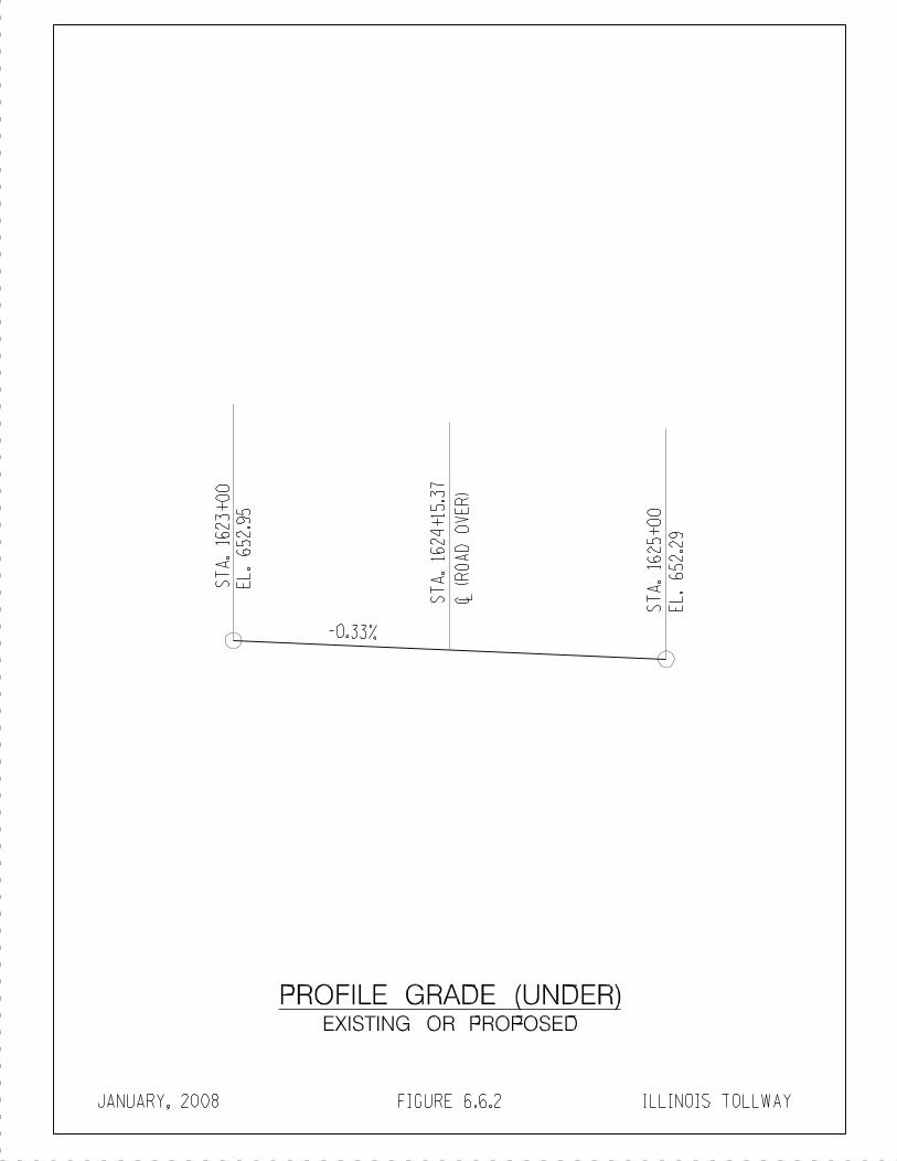
6.6 Profile Sketches
Provide "Profile Grade" sketches for the bridge and all roadways and facilities crossed by the bridge. For examples of "Profile Grade" sketches see Figures 6.6.1 and 6.6.2.
6.7 Location Map
Provide a "Location Map" containing the following information in the lower right hand corner of the sheet. For an example of a "Location Map" see Figure 6.7.1.
• Range, Township, Principle Meridian and Section Numbers
• North Arrow
• Location of Structure
• 4 Township Numbers
• Significant Landmark
6.8 Highway Classification
For grade separations, provide the following information for the Route over and under the proposed structure(s): Route Identification, Class, DHV (existing and future), ADT (existing and future), ADTT (existing and future truck traffic for steel structures only) and Design Speed.
6.9 Railroad Information
For railroad crossings, provide the number, type and time of trains passing over/under the proposed structure each day.
6.10 Waterway Information
For waterway crossings, provide a waterway information table in accordance with Section I-302.02 of the IDOT Drainage Manual.
January 2008 6-2 Illinois Tollway

6.11 Structure Rating The Inventory and Operating Rating for each new, reconstructed or widened structure shall be calculated be the DSE and shown on the General Plan and Elevation Sheet. Also, the DSE shall furnish the Tollway with all of the structure data to perform a “LARS” rating and analysis. This is the same truck overload analysis program used by IDOT. The structure data shall be an electronic file in text file format, line and spacing readable by the “LARS” program. The DSE can use “Bridge Modeler”, an Excel spread sheet or any text file to code the data into a readable format. The readable text file shall include all of the following information.
• Illinois Licensed Structural Engineer, submittal to be signed and sealed • Tollway Bridge Number • Year constructed, program year • Superstructure Type, abbreviated in accordance with LARS requirements • Identification of main load carrying superstructure members; ie, G1, G2 ext., include all
members of different load carrying capacity • Impact factor • Wheel live load distribution factor, as determined by the latest AASHTO Specifications • Number of spans • Section Properties and transition locations • Stirrup or stiffener spacing • Allowable Stresses • Span Lengths • Superimposed dead load
Samples of text file format, line and spacing are available from the Tollway.
6.12 Fracture Critical Details
Fracture critical details shall be identified in the plans.
January 2008 6-3 Illinois Tollway


SECTION 7.0 GENERAL NOTES, INDEX OF DRAWINGS, AND TOTAL BILL OF MATERIAL
7.1 Bridge General Notes
The following general plan notes in addition to those from Subsection 3.1.3 of the latest IDOT Bridge Manual will be included in the Contract Plans, as required.
7.1.1
7.1.2
7.1.3
7.1.4
Cast-In-Place Concrete
All exposed concrete edges shall have a ¾" x 45º chamfer, except where shown otherwise. Chamfer on vertical edges shall be continued a minimum of one foot below finished ground level.
Reinforcement Bars
• Reinforcement bar bending details shall be in accordance with the latest "Manual of Standard Practice for Detailing Reinforced Concrete Structures", ACI 315.
• Reinforcement bar bending dimensions are out to out.
• Bars noted thus, 3x2-#5 indicates 3 lines of bars with 2 lengths of bars per line.
• Cover from the face of concrete to face of reinforcement bars shall be 3" for surfaces formed against earth and 2 inches for all other surfaces unless otherwise shown.
• The number of ties as specified shall be doubled for lap splices at the stage construction line of concrete bridge decks when traffic is allowed on the first completed stage during the pouring of the second stage.
• Slope walls shall be reinforced with welded wire fabric, 6" x 6" - W4.0 x W4.0, weighing 58 pounds per 100 square feet.
Structural Steel
• All bearing and side retainer anchor rods shall be set before bolting diaphragms or cross frames over supports.
• All side retainers shall be installed and bolted down prior to forming and pouring the deck slab.
Construction
• Contractor shall not scale dimensions from the Contract Plans for construction purposes. Scales shown are for information only.
• No construction joints except those shown on the plans will be allowed unless approved by the Engineer.
January 2008 7-1 Illinois Tollway

• The Contractor may request copies of existing construction plans that are currently on file with the Tollway. The request shall be in writing with the understanding that any reproduction cost will be at the Contractors expense.
• It shall be the Contractor's responsibility to verify the location of all utilities prior to starting construction. Contact J.U.L.I.E., 800-892-0123.
• It shall be the Contractor’s responsibility to verify the location of all fiber optic utilities prior to starting construction. The Contractor shall initiate the locate process for the fiber optic cable by completing a “Request to Locate Tollway Facilities” form (Tollway Form A-36) and submitting it to the Tollway. Copies of Form A-36 are available from the Tollway’s Utility/Permit Section (630-241-6800, ext 3306). Completed A-36 forms shall be faxed to the Tollway to the attention of Tollway Utility Administrator at 630-271-7568, at least four (4) business days prior to starting any underground operations, excavations or digging of any type in general area of the fiber optic cable.
• The Contractor shall use care when excavating around existing foundations. Any damage to the existing structure shall be repaired or replaced at the Contractor's expense.
• Existing reinforcement which is to be incorporated into the new construction shall be blast cleaned to grey metal, straightened (without heating), and cut to fit. Cost of which shall be included with that for “Concrete Removal.”
• Temporary soil retention system sheeting, bracing or cofferdams shall be constructed at the locations shown on the plans and/or as required for the excavation to protect the adjacent areas from settling or falling into the excavated areas.
• Concrete sealant shall be applied to the surfaces of all pier and abutment seats, including backwalls located below roadway expansion joints. Sealant shall also be applied to all exposed surfaces of piers in the median or piers, abutments and wingwalls that are adjacent to the roadway.
• After the beams (girders) are set, all elevations for determining fillet heights shall be taken at one time.
• Prior to placing the new concrete for the deck, all loose rust, loose mill scale, loose paint and all other foreign material shall be removed from the embedded portions of steel flanges. The removal shall be accomplished in accordance with the requirements of the SSPC Surface Preparation Specifications SP7 for Brush-Off Blast Cleaning. Cost shall be included with that for “Concrete Removal.” (Use for bridge rehabilitation projects where the complete or partial full depth removal of existing concrete deck is specified, and where cleaning and painting existing structural steel is not specified as an item of work).
• The existing aluminum handrail shall be removed and delivered to the Tollway Maintenance Yard M-______.
January 2008 7-2 Illinois Tollway

• Upon completion of each structure, the Contractor shall measure the resulting horizontal and vertical clearances and submit them to the CM for review and inclusion in the As Built plans (Record Drawings).
• The embankment configuration shown shall be the minimum that must be placed and compacted prior to construction of the abutments and bridge approach slabs.
7.1.5
7.1.6
Demolition Plan
The Contractor must prepare and submit a detailed demolition plan for the partial or complete removal of all curved or heavily skewed (>40deg.) structures to the Tollway for their review. The Contractor may not start any demolition work until their plan has been reviewed and approved.
Erection Plan
The Contractor must retain a firm prequalified by IDOT in the “Design of Complex Bridges” to prepare an erection plan for each curved or heavily skewed (>40 deg.) structure with spans greater than 150 feet. The erection plan will need to be sealed and signed by a Structural Engineer licensed in the State of Illinois. The plan will establish the sequence of erection and indicate the location of all temporary shoring, blocking and hold downs necessary to insure the proper position and stability of the beams or girders. The Construction Engineer responsible for preparing the erection plan shall be on site during erection of the beams or girders to address any problems that may arise.
7.2 Total Bill of Material
Regardless of the placement of a coded "Summary of Quantities" on any other drawing sheet, there shall be a "Total Bill of Material" shown in the plans for each bridge. The "Total Bill of Material" shall be broken down in Superstructure, Substructure, Total and Record Quantities.
7.3 Abbreviations
Provide a list of all abbreviations and their meanings which will be used on the drawings. A list of some typical abbreviations are shown below.
P.G.L. PROFILE GRADE LINE I.F. INSIDE FACE N.B.L. NORTH BOUND LANES O.F. OUTSIDE FACE S.B.L. SOUTH BOUND LANES P.J.F. PREFORMED JOINT FILLER S. ABUT SOUTH ABUTMENT P.J.S. PREFORMED JOINT SEALER N. ABUT NORTH ABUTMENT BK/ BACK OF E.F. EACH FACE B/ BOTTOM OF F.F. FRONT FACE T/ TOP OF B.F. BACK FACE PROP. PROPOSED
7.4 Index of Sheets
Provide an Index of Sheets for each bridge. The index shall list all of the sheet numbers and titles that are part of the bridge plans. The titles in the index must exactly match the individual sheet titles.
January 2008 7-3 Illinois Tollway

SECTION 8.0 CONSTRUCTION STAGING
8.1 General
The construction staging plans shall clearly identify all stages of the bridge construction. The staging plans shall also show all details for temporary, existing or proposed deck slab, beams or substructure required during each stage of the construction. For an example of a Construction Staging Plan, see Figure 8.1.1. Construction stage lines shall be located and dimensioned in all plan views and cross sections. The bridge design shall verify that the bridge and adjacent roadway staging match. Stage Lines within the traveled way shall match lane lines.
8.2 Temporary Concrete Barriers
The Construction Staging Plans shall also show the location of all temporary concrete barriers for each stage of construction, where barriers are required. The temporary concrete barrier shall be anchored to the existing deck slab or blocked in place on a new slab when the distance from the back of the barrier to the edge of the slab is less than 3’-6”. See IDOT’s Base Sheet.
8.3 Protective Shield System
A drawing or drawings shall be included in the bridge plans to define the limits of a protective shield system when it is required. The quantity of protective shield system to be installed shall be stated within the Plans. Removal of PROTECTIVE SHIELD SYSTEM shall not be measured for payment. For projects using IDOT Standard Specifications a Special Provision is necessary to provide for Protective Shield for the new structure as well as removal of the old structure. The Contractor is responsible for the convenience and safety of the public during erection and construction of each element of the structure in accordance with Section 107.09 of the latest Tollway Supplemental Specifications.
A protective shield system will be required under the superstructure or at the lower level of the superstructure whenever equipment, falling objects or material may cause damage to existing aerial wire lines, railroads, streets, highways, regulatory waterways, vehicular or waterway traffic or injury to pedestrians, persons in vehicles or water craft or to others. The lateral limits of the protective shield system are shown below:
Case Construction or Reconstruction
Transverse Limits of Protective Shield System
1 New construction Outside of new parapet + 2' to outside of new parapet + 2'
2 Deck and superstructure widening
Existing fascia beam to outside of new parapet + 2'
3 Deck removal and replacement Outside of parapet + 5' to outside of parapet + 5'
4 Deck replacement and widening Outside of new parapet + 2' to outside of new parapet + 2'
The limits of the protective shield system for bridge projects limited to full and partial depth deck patching will be set considering the area of the deck to be improved. At a minimum protective shield system will extend 10’ beyond the expected limits and at least 5’ beyond actual limits of partial or full depth repair above traffic.
January 2008 8-1 Illinois Tollway


SECTION 9.0 SUBSTRUCTURE AND SHEET PILING LAYOUTS
9.1 Substructure Layout
The basic geometry for the location of the substructure must be clearly shown on the plans. All elements of the substructure must be referenced to the same single longitudinal reference line. For an example of a substructure location plan on tangent alignment see Figure 9.1.1. For an example of a substructure layout on curved alignment see Figures 3.1.8-2 and 3.1.8-3 of the latest IDOT Bridge Manual.
9.2 Pile Numbering
On any structure, proposed to be supported on piling, a "Pile Driving Record" table shall be included with the substructure layout or on a separate plan sheet. The "Pile Location" and "Pile Number" column will be completed during design leaving some additional rows for field changes during construction. The pile numbering system will be used to identify the individual pile and its location in the substructure and "Pile Driving Record". For an example of the pile numbering system and driving record, see Figure 9.1.1 and Figure 9.2.1. This data is for record purposes and shall be filled in by the CM during pile driving.
9.3 Drilled Shaft Numbering
On any structure proposed to be supported by caissons, "Drilled Shaft Installation Record" table shall be included with the substructure layout or on a separate plan sheet. The "Shaft Mark" column will be completed during design leaving some additional rows for field changes during construction. The drilled shaft numbering system will be used to identify the individual drilled shaft and its location in the substructure and "Drilled Shaft Installation Record". For an example of the drilled shaft installation record, see Figure 9.3.1. This data is for record purposes and shall be filled in by the CM during drilled shaft construction.
9.4 Temporary Soil Retention Systems (TSRS)
The location and limits of the TSRS shall be shown and identified on the substructure location plan and/or separate plan sheets in accordance with Section 3.13 of the latest IDOT Bridge Manual. The DSE shall specify the use of TSRS wherever possible. Temporary sheet piling shall only be used when site conditions and/or constraints preclude the use of TSRS or where cofferdams are required to construct elements of the substructure underwater.
The following note shall appear on the substructure location plan when TSRS are required:
“The information shown for TSRS is estimated. It is the Contractor’s responsibility to provide a design and details for each TSRS, complete with calculations and drawings, sealed by an Illinois licensed Structural Engineer, for the Engineer’s review.”
9.5 Temporary and Permanent Sheet Piling
The location and limits of all temporary and permanent sheet piling shall be clearly shown and identified on the substructure location plan and/or separate plan sheets in accordance with Sections 3.13 and 3.13.1 of the latest IDOT Bridge Manual. The cut off elevation for any part that is to remain in place shall also be shown.
January 2008 9-1 Illinois Tollway

The inside face of the temporary sheeting shall be offset 2'-0" from the proposed footing; while the inside face of the permanent sheeting will be located along the edge of the footing.
The following note shall be added to the plans if a stiff or dense soil layer is present which may require jetting and/or a larger hammer to penetrate:
“Hard driving may be encountered during the sheet piling installation. The Contractor shall provide the appropriate driving equipment for the soil conditions indicated on the boring logs.”
9.6 Cofferdams
Cofferdams shall be used to construct all elements of the substructure which are located in water. When shallow water is present; i.e., less than 2 feet, other methods of water control that allow the Contractor maximum flexibility during construction may be considered.
The location and limits of all cofferdams shall be clearly shown and identified on the substructure location plan. The top and bottom elevations of the cofferdam shall also be shown, as well as the cutoff elevation for any part that is to remain-in-place. The inside face of the cofferdam shall be offset 1'-0" from the proposed footing. The seal coat shall be designed in accordance with the latest IDOT Bridge Manual 3.13.3.
The following note shall appear on the substructure location plan when cofferdams are required:
“The information shown for cofferdams is estimated. It is the Contractor's responsibility to provide a design and details for each cofferdam, complete with calculations and drawings, sealed by an Illinois licensed Structural Engineer, for the CM’s review.”
9.7 Temporary Sheeting and Bracing for Railroads
Excavations adjacent to active railroad tracks or substructure elements supporting railway operations shall be protected by temporary sheeting and bracing system designed and detailed in the Contract Plans. The system shall be designed in accordance with the latest AREMA, AASHTO and IDOT Specifications.
9.8 Structural Sub Drains
The location and limits of structural sub drains behind abutments and wingwalls including invert elevations, slopes, and outfalls shall be shown on the substructure location plan.
January 2008 9-2 Illinois Tollway


PILE
DR
IVIN
G R
ECO
RD
D
ate
Pile
s D
riven
:
(M
onth
Yea
r)
Type
& S
ize
of P
ile U
sed:
Pile
Driv
ing
Equi
pmen
t Use
d:
En
ergy
Rat
ing:
Ham
mer
Use
d:
Type
St
roke
W
eigh
t
Form
ula
Use
d To
Cal
cula
te C
apac
ity:
Pile
Driv
ing
Con
trac
tor:
C
M:
Driv
ing
Dat
a Fo
r The
Fin
al 5
Ft.
- Blo
ws
Pile
Lo
catio
n Pi
le
Num
ber
Gro
und
Surf
ace
Elev
atio
n C
ut-o
ff El
evat
ion
Pene
trat
ed
Leng
th, F
t 5'
to
4'
4' to
3'
3'
to
2'
2' to
1'
1'
to
0'
12"
to
6" *
6" to
0"
* C
apac
ity
Tons
R
emar
ks
NO
TE: *
For
pile
s dr
iven
to re
fusa
l, bl
ow c
ount
for t
he la
st fo
ot s
hall
be re
cord
ed in
6 in
ches
incr
emen
ts.
Pile
dam
age,
obs
truct
ion,
pile
reje
ctio
n, te
st p
iles
etc.
sha
ll be
reco
rded
in R
emar
ks c
olum
n.
Janu
ary
2008
FI
GU
RE
9.2
.1
Illin
ois
Tollw
ay

DR
ILLE
D S
HA
FT IN
STA
LLA
TIO
N R
ECO
RD
Soil
Des
crip
tion
Shaf
t M
ark
Shaf
t D
ia.,
Ft.
Bel
l D
ia.,
Ft.
Bot
tom
El
evat
ion
Aro
und
Bel
l A
t Bot
tom
of
Sha
ft
Qu=
Unc
onfin
edC
ompr
essi
ve
Stre
ngth
, tsf
Moi
stur
eC
onte
nt%
Rat
io o
f D
epth
to
Dia
met
er
Fiel
d B
earin
g Pr
essu
reks
f*
Tem
pora
ryC
asin
g U
sed
Leng
th,
Ft.
Rem
arks
*F
ield
bea
ring
pres
sure
sha
ll be
cal
cula
ted
base
d on
unc
onfin
ed c
ompr
essi
ve s
treng
th a
nd ra
tio o
f dep
th to
dia
met
er o
f bel
l. Th
e fie
ld b
earin
g pr
essu
re s
hall
be 1
.5 ti
mes
Qu
if th
e ra
tio o
f the
dep
th o
f the
dril
led
shaf
t mea
sure
d fro
m th
e to
p of
the
shaf
t to
the
botto
m o
f the
bel
l (or
bot
tom
of s
haft
if no
bel
l is
pres
ent)
to th
e di
amet
er o
f the
bel
l (or
sha
ft if
no b
ell i
s pr
esen
t) is
equ
al to
or
gre
ater
than
4.0
. If t
he d
epth
to d
iam
eter
ratio
is le
ss th
an 4
.0, t
he E
ngin
eer s
houl
d co
ntac
t the
Tol
lway
. Ja
nuar
y 20
08
FIG
UR
E 9
.3.1
Ill
inoi
s To
llway

SECTION 10.0 ABUTMENTS
10.1 General
Abutments shall be designed in accordance with the latest AASHTO Specifications and Section 3.8 of the latest IDOT Bridge Manual, except as herein modified.
10.2 Design
The friction force caused by an expansion bearing sliding on its bearing plate or deforming on the supporting substructure element must be included in the design of the substructure. These forces are determined by multiplying the coefficient of friction by the total dead load reactions on the bearing.
For steel on steel, use a coefficient of 0.30, for self-lubricating bronze on steel a coefficient of 0.15 and teflon on teflon, use a coefficient of 0.10.
For elastomeric bearings the force required to deform the elastomeric pad is found by the following equation:
F = (Modulus in Shear) (Contact Area) (Deflection Due to Temperature)Effective Rubber Thickness
The magnitude of this force shall not be less than 25 pounds per square inch of bearing area for Type I bearings or 0.04 times the dead load reaction for Types II and III bearings.
10.3 Abutment Types
Integral, semi-integral or vaulted abutments shall be utilized whenever possible for new grade separation structures. Stream and railroad crossings shall use either integral or pile bent abutments. High wall abutments may be considered where there is insufficient clearance to construct a vaulted abutment.
• Integral abutments shall be used with steel girder designs, cast-in-place concrete slabs, or precast, pre-tensioned concrete girders. Girders shall be composite with a cast-in-place concrete deck. The superstructure shall be designed and constructed as a continuous unit between abutments.
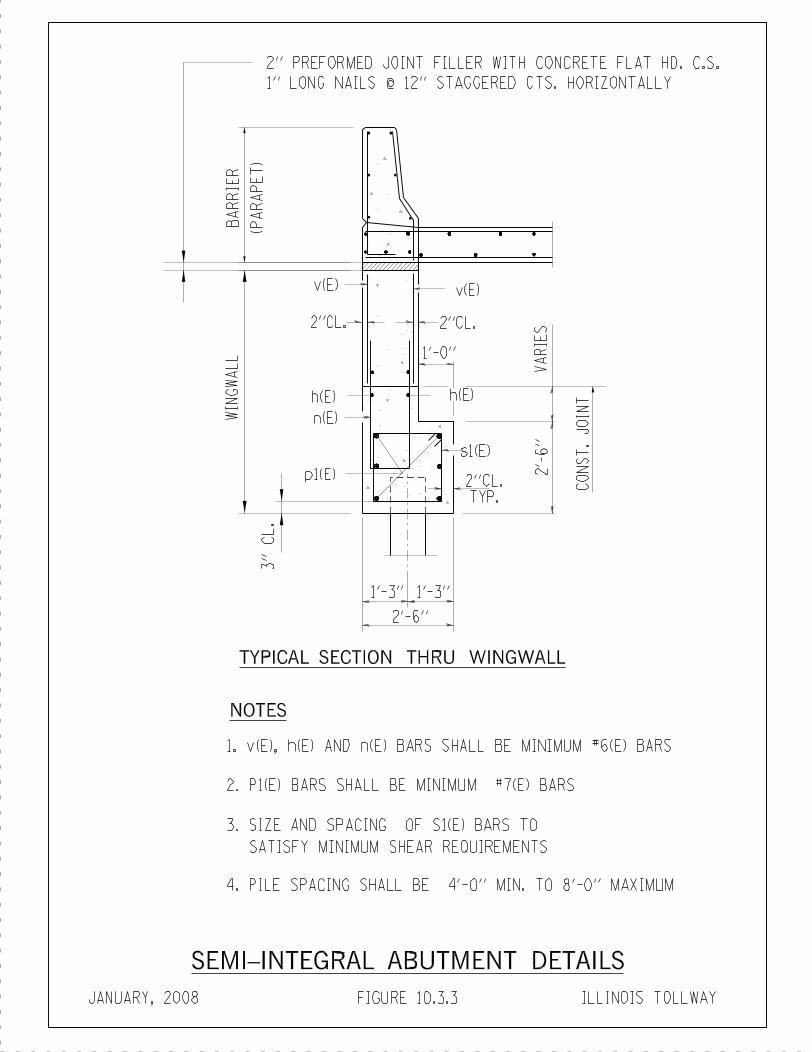
• Semi integral abutments shall be utilized where soil conditions require the use of two or more rows of piles to support the proposed abutment. Regardless, the superstructure shall be designed and constructed as a continuous unit between the abutments. The semi-integral concept may also be utilized to eliminate expansion joints at existing stub abutments. However, the existing backwall and part of the approach slab will need to be reconstructed. The existing superstructure may also need to be made composite and continuous between the modified abutments, if it is not already. See Figures 10.3.1, through 10.3.4 for details.
• Pile bent (stub) abutments shall be utilized for bridges crossing streams or railways when the proposed span lengths or skew angles exceed those specified for integral abutments.
January 2008 10-1 Illinois Tollway

• Sand filled or voided vaulted abutments are constructed on the approach slope and may be used to increase the length of structure without changing the length or depth of the main spans. Their use shall be considered on a case by case basis, provided they are more economical than increasing the length and depth of the main span, and constructing a pile bent abutment.
• Highwall abutments may be utilized to eliminate the need for approach spans and/or reduce span length and superstructure depth where site constraints or vertical clearance preclude the use of either pile bent or vaulted abutments.
10.4 Abutment Foundations
10.4.1 Piles
Piles for foundations shall be designed in accordance with the Section 3.10 of the latest IDOT Bridge Manual.
Piles used in integral abutments shall be placed in a single row. Steel "H" piles are preferred for structure lengths up to 200 feet and required for structure lengths between 200 feet and 450 feet.
The following information shall be included on Abutment sheets when piles are used:
PILE DATA PILE TYPE AND SIZE: NOMINAL REQUIRED BEARING: FACTORED RESISTANCE AVAILABLE OR ALLOWABLE RESISTANCE AVAILABLE: ESTIMATED PILE LENGTH: NUMBER OF PILES REQUIRED: _______ plus ______test pile(s) LEGEND - DENOTING THE FOLLOWING: EXISTING PILES EXISTING BATTERED PILES PROPOSED PILES PROPOSED BATTERED PILES TEST PILES
10.4.2 Drilled Shafts
Drilled shafts shall be designed in accordance with Section 3.10 of the latest IDOT Bridge Manual.
10.5 Widening Existing Abutments
In general, abutments shall be widened in kind, especially those which can be viewed by the traveling public. At locations not exposed to the traveling public, such as structures over railroads or streams, other types of designs may be considered. The final selection will be based on serviceability and economics.
Foundations for widened abutments widened to the outside shall be the same type as the existing. However, construction procedures and type of construction shall be considered when
January 2008 10-2 Illinois Tollway

placing new foundations adjacent to existing so as not to reduce the load carrying capacity or cause settlement of existing foundations. Existing soil borings and new soil borings (if required) shall also be considered in the final selection. Abutment widenings shall be designed to carry any longitudinal or transverse forces passed through the bearings from the superstructure. Abutments to the outside shall be tied to the existing with dowel bars drilled into the existing concrete.
Abutments for structures widened to the inside forming a median closure, will be separated along the centerline of the Tollway with a preformed joint filler and a 6 inch non-metallic water seal. Abutments widened to the inside shall be tied to the existing with dowel bars drilled into the existing concrete.
10.6 Bridge Seats
The bridge seats shall be constructed in steps poured monolithically with the abutment. The minimum step shall be ¾ inches. Metal shims shall be provided for each bearing if step is less than ¾ inches. The elevation and height of each step shall be shown on the plans. Steps shall be reinforced when one or more of the preceding steps exceed 4 inches; see Figure 10.6.1 and 10.6.2. In all cases, the bridge seats between the bearings shall be sloped ¼ inch to drain. The bearing seat shall meet the minimum support length requirements specified in the AASHTO Seismic Design Section for Seismic Performance Category A.
10.7 Slope Paving
10.7.1
10.7.2
10.7.3
10.7.4
New Bridges - Grade Separation Structures
Grade separation structures shall have 4 inch thick reinforced concrete slopewalls, as shown in the Standard Drawings.
New Bridges - Stream Crossings
Stream crossings shall have 6 inch thick reinforced concrete or stone riprap slopewalls, as shown in the Standard Drawings.
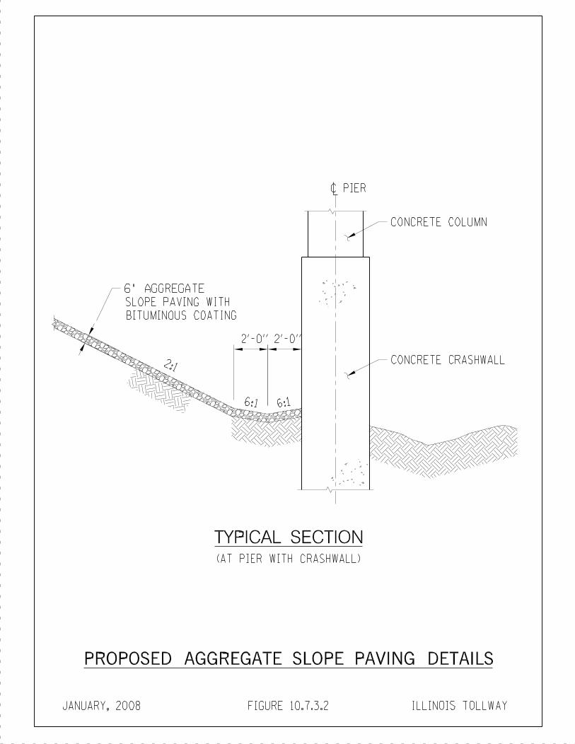
New Bridges - Railroad Crossings
Railroad crossings shall have 6 inch thick bituminous coated aggregate slope paving, as shown in Figures 10.7.3.1 and 10.7.3.2.
Existing Bridges
Bridge abutment slopes on existing bridges to be rehabilitated shall be repaired and restored to the original design configuration. Slopes on bridges to be widened shall be protected with the same design as the existing bridge. Slopes which do not have any slope protection shall be covered with 6 inches of aggregate slope paving unless there are floor drains in the deck above; in which case they shall be paved with a 4 inch thick reinforced concrete slopewall.
January 2008 10-3 Illinois Tollway


SECTION 11.0 PIERS
11.1 General
Piers shall be designed in accordance with the latest AASHTO specifications and Section 3.9 of the latest IDOT Bridge Manual, except as herein modified.
11.2 Design
The friction force caused by an expansion bearing sliding on its bearing plate or deforming on the supporting substructure element must be included in the design of the structure. These forces are determined by multiplying the coefficient of friction by the total dead load reactions on the bearing.
For steel on steel, use a coefficient of 0.30, for self-lubricating bronze on steel a coefficient of 0.15 and Teflon on Teflon, use a coefficient of 0.10.
For elastometric bearings the force required to deform the elastometric pad as found by the following equation:
F = (Modulus in Shear) (Contact Area) (Deflection Due to Temperature)Effective Rubber Thickness
The magnitude of this force shall not be less than 25 pounds per square inch of bearing area for Type I bearings or 0.04 times the dead load reaction for Types II and III bearings.
The fixed pier(s) design shall include the “net” frictional force from the expansion bearings of adjacent piers.
The bearing seat shall meet the minimum support length requirements specified in the AASHTO Division I-A Seismic Design Section for Seismic Performance Category A.
11.3 Pier Types
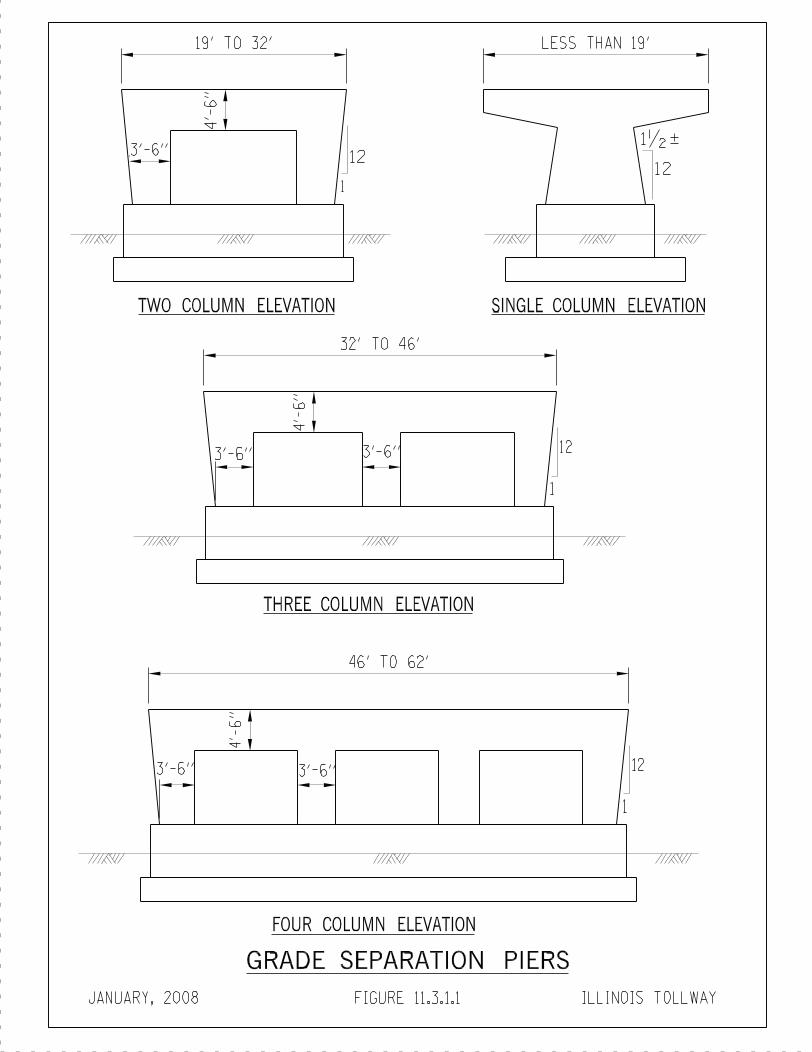
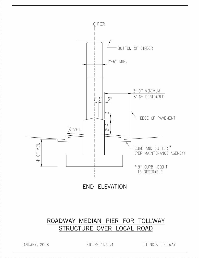
11.3.1 Grade Separation Piers
Grade separation piers shall be proportioned in accordance with the dimensions as shown on Figures 11.3.1.1 through 11.3.1.6. Care shall be used in applying this criteria on piers with heights greater than 20'-0" measured from the top of crash wall.
The minimum width of a grade separation pier shall be 2'-6". This minimum dimension shall be followed unless additional width is required for the bearings. In which case the width of the pier cap may be increased up to 6 inches before the width of the column would need to be increased. The top surface of the pier cap shall be stepped between girders to obtain required girder seat elevations; see Figure 10.6.2.
Grade separation piers used with short spans and integral abutments may be supported by a single row of piles, provided the capacity of the piles is not exceeded. Otherwise, a larger footing with multiple rows of piles shall be used. See Figure 11.3.1.6 for details of the short span integral pier.
January 2008 11-1 Illinois Tollway

11.3.2
11.3.3
Stream Crossing Piers
Stream crossing piers shall be solid with rounded ends. The sides shall be vertical unless a wider wall base is required, in which case the sides of the pier shall be battered. If a greater width is needed for bearing seats, consideration shall be given to using a wider cap while maintaining a constant 2'-6" pier width. Details of a stream crossing pier are shown on Figure 11.3.2.1 and 11.3.2.2.
Railroad Crossings
Railroad crossings shall utilize grade separation type piers unless they are adjacent to the tracks, in which case they shall be modified with crash walls meeting the requirements of the latest edition of A.R.E.M.A. and the railroad. See Figure 11.3.3.1 for details.
11.4 Widening Existing Piers
In general, existing piers shall be widened in kind, especially those which can be viewed by the traveling public. At locations not exposed to the traveling public, such as structures over railroads or streams, other designs may be considered. The final selection will be based on serviceability and economy.
Pier widenings shall be designed to carry all forces which pass through the bearings. All pier widenings shall be tied to the existing cap, column and footing areas with dowel bars drilled into the existing concrete. Minimum depth embedment of dowels in existing concrete shall be 12 inches for vertical bars and the development length for horizontal bars. Maximum spacing shall be 18 inches.
Foundations for widened piers shall be the same type as the existing structure. Existing soil borings and new soil borings (if required) shall also be considered in the final selection. Construction procedures and type of construction shall be considered when placing new foundations adjacent to existing so as not to reduce the load carrying capacity or cause settlement of existing foundations.
Special attention shall be given to the widening of existing piers that consist of 3 foot diameter hollow precast columns without footings. These shall be designed using a 3 foot diameter column supported on a pile foundation.
Generally piers at dual crossings which are to be widened each side of the centerline of median, will be separated along the centerline with an open joint or preformed joint filler, except for their footings which shall be constructed without an expansion joint. If a construction joint in the footing is needed, there shall be longitudinal reinforcing crossing the joint as required to maintain continuity.
Pier caps with rounded ends shall be attached to the new work as shown in Figure 11.4.1. Pier walls with rounded ends shall be attached to the new work as shown in Figure 11.4.2.
11.5 Integral Pier Caps
An integral pier cap is a pier cap where the pier cap is incorporated either entirely or largely within the depth of the superstructure. The cap can be constructed of either concrete or steel. For steel superstructures, the longitudinal girders are typically run continuous through the cap. When the superstructure is constructed of prestressed concrete, a pier segment may run
January 2008 11-2 Illinois Tollway

continuous through the cap or the ends of beams may be cast into the integral cap. When the beams are not continuous through the cap, a positive connection is made between the cap and the beams. This connection is generally made with post-tensioning.
In many cases the cap is supported by a single column at or near the center or at each end. The resulting long slender spans beyond or between the column(s) contribute to the necessity for post-tensioning concrete caps.
Integral pier caps may be utilized to: Improve vertical clearances, simplify framing, eliminate bearings, improve aesthetics and reduce the mass of the structure which reduces the seismic design forces.
11.6 Pier Base Walls
All piers on grade separation structures shall be equipped with a crash wall which extends a minimum of 2'-4" or 4'-6" above the ground. When a guardrail is to be installed running around the face of the pier, the ground elevation shall be computed at the face of the guardrail. For crash walls poured integrally with piers, the top of wall shall typically follow the profile grade of the edge of shoulder. A level or tangent top of wall may be used for those cases where the maximum height does not exceed the minimum by more than 3 inches.
11.7 Pier Columns
If pier columns are over 20 feet high, a construction joint or joints should be detailed at approximately mid-height or third points.
11.8 Foundations
11.8.1 Spread Footings
The minimum width of any spread footing under an expansion pier shall be one-fourth the distance from the top of the pier to the bottom of the footing. If the spread footing is founded on rock, this ratio may be reduced to one-fifth of the pier height, and keyed a minimum of 6 inches into sound rock. The maximum applied and allowable bearing pressure for each pier shall be shown on the appropriate plan sheet.
Any construction joints allowed in pier footings shall be bonded construction joints with continuous reinforcement.
January 2008 11-3 Illinois Tollway

11.8.2 Piles
Piles for foundations shall be designed in accordance with Section 3.10 of the latest IDOT Bridge Manual.
The minimum width between the outside rows of piles in a pile supported footing shall be one-fifth of the pier height.
The following information shall be included on the Pier sheets when piles are used:
PILE DATA PILE TYPE AND SIZE NOMINAL REQUIRED BEARING: FACTORED RESISTANCE AVAILABLE OR ALLOWABLE RESISTANCE AVAILABLE: ESTIMATED PILE LENGTH: NUMBER OF PILES REQUIRED: _______ plus ______test pile(s) LEGEND - DENOTING THE FOLLOWING: EXISTING PILES PROPOSED PILES PROPOSED BATTERED PILES TEST PILES
11.8.3 Drilled Shafts
Drilled shafts shall be designed in accordance with Section 3.10 of the latest IDOT Bridge Manual.
January 2008 11-4 Illinois Tollway


SECTION 12.0 STRUCTURAL STEEL
12.1 General
The design and detailing of steel superstructures shall be in accordance with the appropriate AASHTO Specifications and the provisions of Section 3.3 of the IDOT Bridge Manual except as herein modified.
12.2 Design
Structural steel shall be AASHTO M270 Grade 50 (ASTM A709) unless otherwise noted. Grade 70 steel may be used in areas of high stress if this will result in a more economical solution.
All horizontal curved structured and/or structures skews greater than 40 deg. shall be designed and/or checked by three dimensional analysis. If either type of structure is to be constructed in stages, the girders in each stage shall be checked by three dimensional analysis for stability, deflection and stress. For these conditions the DSE should consider using a smaller (15’-20’) cross section.
Generally, all shop connections shall be welded. All field connections shall be made with ⅞ inch diameter zinc coated high strength bolts AASHTO M164 (ASTM A325) and shall be designed as friction type connections.
Composite design shall be used for simple spans and in the positive moment regions of continuous spans. In the negative moment region of continuous composite spans #6 bars at 12 inch spacings shall be provided for crack control in the deck slab in addition to the normal top distribution steel.
In order to minimize fillet heights on steel structures, the beam or plate girder slopes shall be changed at the splices to conform to the general configuration of the bottom of the formed deck slab.
Plate girders shall be cambered for dead load deflection and vertical curve geometry except where the resulting camber would be less than one inch.
A table showing top of beam elevations for rolled beams, at the abutments, piers and splices, for rolled beams or top of web elevations for plate girders shall be shown in the plans.
12.3 Intermediate Vertical Stiffeners
Intermediate vertical stiffeners shall be a minimum of 7/16 inch thick and shall be welded to the web with a ¼ inch minimum continuous fillet weld. The distance between the end of the stiffeners and the near edge of the web-to-tension-flange fillet weld shall be no more than six times or less than four times the web thickness.
For plate girders with webs equal to or smaller than 54 inches, it is preferable not to utilize intermediate stiffeners. For plate girders with webs larger than 54 inches, the web thickness may be increased to a maximum ⅝ inches to eliminate or limit the vertical stiffeners to only one or two locations per span beyond those provided for cross frame attachments. The minimum web thickness of a plate girder shall be 7/16 inches.
January 2008 12-1 Illinois Tollway

12.4 Bearing Stiffeners
Bearing stiffeners need not be welded to either flange of rolled beams or plate girders, except as hereafter indicated. They shall be milled on the bearing end and have a tight fit at the other end.
On all skewed plate girders, or rolled beams with skews 45 deg. and larger and on all horizontally curved beams and plate girders, the bearing stiffeners shall be welded to both flanges where these stiffeners are used as connecting plates for cross frames or diaphragms. The welding to the flanges shall be done with fillet welds on both sides of stiffeners. The length of the fillet weld at the mill to bear end shall be the width of the stiffener minus 1 inch (½ inch each end). The length of the fillet weld at the other end shall be the full width of stiffener. The bearing stiffener plates at the junction of the flanges and the web shall be clipped 1 inch horizontally and a minimum vertically of 1½ inch for rolled beams or four times the web thickness plus the size of web-to-flange fillet weld for plate girders.
12.5 Superstructure Diaphragms
12.5.1
12.5.2
12.5.3
End Diaphragms and Cross Frames at Expansion Joints
End diaphragms at expansion joints located over piers and/or abutments shall consist of a thickened slab supported on an end diaphragm or cross-frame as shown in the IDOT Bridge Manual.
Diaphragms and Cross-Frames at Expansion Bearings
Steel diaphragms and cross-frames at expansion piers or abutments shall be designed to allow for jacking on the diaphragm or cross-frame for resetting, repair or replacement of expansion bearings. The points on which jacking may occur shall be shown on the drawings.
Diaphragms and Cross-Frames at Intermediate Points
The connecting plates for the cross frames and diaphragms near the support within a distance equal to twice the girder depth for all plate girders shall be welded to both flanges. This requirement shall also apply to the cross frames and diaphragms in all other areas for skewed and horizontally curved plate girders only. (In these cases, flange stress shall be investigated for fatigue under Category C).
Cross frames for horizontally curved plate girders and girders with skews greater than 40 deg. shall be designed and detailed with top and bottom chord members. The cross frames shall be orientated in straight line, perpendicular, to the fascia girders. Cross frames shall not be staggered or placed parallel to the skew for horizontally curved or heavily skewed structures.
For non-skewed girders, the connecting plates for the cross frames and diaphragms in all areas other than the areas near the supports should be welded to the compression flange and be undercut at the tension flange. The distance between the near edge of the web-to-tension-flange weld and the end of the connecting plate shall be six times the web thickness. Special consideration shall be given to the connections between the floor beams and the main girder for two-girder system bridges to prevent fatigue cracking in the webs.
January 2008 12-2 Illinois Tollway

12.6 Table of Moments and Shears
To provide ready information for any future analysis of a structure and to provide the reviewing agencies with a basis for checking of the design, all detailed bridge plans shall present as a part of said plans a table of moments and shears. Refer to the latest IDOT Bridge Manual for the suggested table layouts.
January 2008 12-3 Illinois Tollway

SECTION 13.0 PRECAST PRESTRESSED CONCRETE (PPC)
13.1 General
The design and detailing of PPC I-Beams and bulb T-girders shall be in accordance with the latest AASHTO Standard Specifications for Highway Bridges and Section I of the latest IDOT Prestressed Concrete Manual except as herein modified.
13.2 Design
The prestressing strands used in PPC beam designs shall be, low relaxation strands with an area of 0.153 or 0.167 square inches.
The 28-day concrete strength for prestressed girders shall be 6,000 psi and may be increased to a maximum of 7,000 psi with a preferred maximum of 6,800 psi. The higher strength, above 6,000 psi, shall be used only when economical. Concrete strengths at strand release shall be a minimum of 4,000 psi and a maximum of 5,200 psi.
All new bridges and bridge reconstructions on the Tollway will be designed for HL 93.
In the design of continuous composite PPC structures, the superimposed dead load, live load and impact stresses shall be computed on the basis of full continuity at the interior supports.
The final compressive stress in the bottom flange of the PPC beams at piers for continuous designs shall be calculated at the strand load transfer point (assumed to be at the strand transfer length from the end of the beam) and the edge of bearing pad or diaphragm.
Vertical stirrups are required at the ends of all prestressed beams to resist 6% of the total initial prestressing force at 18 ksi located within a distance of ¼ of the girder depth from the end of the beam. For 63 inch and 72 inch beams the minimum stirrup reinforcing shall be 5 pairs of #6 bars.
13.3 Details
Seven PPC I-Beam sections can be used on the Tollway system. The first one is a standard 28 inch WisDOT section. The next four are standard 36 inch, 42 inch, 48 inch and 54 inch IDOT I-Beams. The remaining sections are 63 inch and 72 inch IDOT Bulb Tee (BT) beams.
The 28 inch I-Beam shall only be used where a proposed widening would require a shallower section to preserve the existing vertical clearance. See Figure 13.3.1 for details.
The 63 inch BT and the 72 inch BT beams will be used on Tollway Bridges for span lengths requiring these depths. See Figure 13.3.2 for additional details.
While it is the Tollway's intent to continue to follow IDOT’s policy to design prestressed girders with draped strand, there may be situations where a well documented request to use debonding may be considered.
When 63 inch and 72 inch girders are used for spans in excess of 120 feet, calculations shall be provided for the lateral stability of the girders during shipping, handling, and erection and
January 2008 13-1 Illinois Tollway

submitted for approval to the Engineer. The calculations shall be sealed and signed by a licensed Illinois Structural Engineer.
At all piers supporting continuous spans, a minimum of two #8 bars for I-Beams and three #8 bars for BT beams shall be added to the bottom flange, projecting beyond the beam end in accordance with the details shown in Figures 13.3.3 and 13.3.4.
When beams exceed 100 feet in length, the DSE shall verify that a precaster, certified by the Precast Prestressed Concrete Institute (PCI) will be capable of manufacturing and transporting the beams to the bridge site within the project schedule. For bridges requiring beams exceeding 100 feet in length, the following note shall be added to the list of General Notes.
“The manufacturer, the Contractor and the beam transportation company shall provide adequate bracing and support for the PPC beams during handling, transporting, storing and erecting to ensure the safety of the personnel associated with the construction of the project.”
13.4 Table of Moments and Shears
To provide ready information for any future analysis of a structure and to provide the reviewing agencies with a basis for checking of the design, all detailed bridge plans shall include a table of moments and shears. See Subsection 3.1.12 of latest IDOT Bridge Manual for an example of a moment and shear table for PPC I-Beams.
13.5 Superstructure Diaphragms
13.5.1
13.5.2
13.6.1 Introduction
Pier Diaphragms
Fixed piers shall be attached to the superstructure by full depth diaphragms using the details shown in Figures 13.5.1.1 and 13.5.1.2. Expansion piers shall be separated from the superstructure by partial depth diaphragms and expansion bearings as shown in Figures 13.5.1.3 and 13.5.1.4.
The design of expansion diaphragms shall include provisions to allow jacking on the diaphragms to lift the beam ends for resetting, repair or replacement of bearings. If jacking cannot be done on the end diaphragms, provisions shall be made in the design of the beam seat to allow jacking directly under the beam. The jacking locations shall be shown on the drawings.
End Diaphragms at Expansion Joints
End Diaphragms at double expansion piers and abutments shall consist of a thickened deck slab as shown in Figure 13.5.2.1.
13.6 Extending Spans
Precast Bulb Tee beams have been used with great success all over the country for the construction of much longer spans (200-300 foot range) than can normally be achieved with precast concrete girders. The spliced girder concept has been used mostly to extend spans, but can also be used to reduce construction depth.
January 2008 13-2 Illinois Tollway

The Tollway is presently constructing a large project using Spliced Post-Tensioned Bulb Tee girders and will consider other applications as opportunities arise. This type of construction generally competes well with steel plate girders in the 200 to 300 foot span range.
Before considering this method in the TS&L stage, designers should survey precasters in the general project area and determine if there is interest and capability on the part of precasters to manufacture the beams cost effectively and that they are able to ship them to the project site.
13.6.2 Design
13.6.3
13.6.4
• The design requires specialized software capable of evaluating the time dependent effects of creep, shrinkage and relaxation on moments and deflections and the effects of sequential construction steps.
• The design shall meet the requirements of the latest AASHTO Bridge Design and AASHTO Guide Specifications for Segmental Bridges.
• The latest edition of the Prestressed Concrete Institute (PCI) Bridge Manual.
• The latest editions of the Post – Tensioning Institute (PTI) for post-tensioning and grouting of tendons.
• The latest Florida Department of Transportation (FDOT) Specifications for the design and construction of spliced I-girder bridges.
• National Cooperative Highway Research Program (NCHRP) Report 517, “Extending Span Ranges of precast prestressed concrete girders.
Durability
NCHRP Report 517 discusses the durability of spliced I-girders extensively. The main issue is the lack of quality control during the grouting of post-tension ducts. The Contractor shall submit to the CM for review and approval a GROUTING PLAN and MANUAL setting out the procedures he or she intends to follow. Bleed tubes shall be installed in accordance with FHWA recommendations. In addition, the CM and the Contractor’s key staff involved with the project should attend grouting classes and obtain appropriate certification.
Splices and Splice Locations
Spliced I-girder bridges shall be constructed with cast-in-place splices. Match cast splices are not permitted.
The location of splices will determine the length and weight of the sections and thus affect transportation and construction. Splices have to meet both serviceability and strength requirements. Protruding reinforcing must be provided to control both conditions. The CM shall require the shop drawings to show how ducts are to be spliced.
Report 517 discusses extensively how the AASHTO LRFD code applies to spliced I-girder bridges and suggests revisions to the LRFD code which would eliminate situations where application of the code to spliced I-girders is vague. The report also recommends the use of the AASHTO GUIDE LINES for DESIGN and CONSTRUCTION of SEGMENTAL BRIDGES.
January 2008 13-3 Illinois Tollway

13.6.5
13.6.6
13.6.7
13.6.8
13.6.9
13.6.10
13.6.11
Pretensioning and/or Post-tensioning
Pretensioning is generally more cost effective than post-tensioning. Therefore, the design approach should be to maximize pretensioning and minimize post-tensioning. The required forces should be provided by the post-tensioning tendons that can be conveniently placed in the section and the balance by pretensioning strand.
Size of Post-Tensioning Tendons
Post-tensioning duct sizes should be limited to 40% of the web thickness. The corresponding tendon size for an 8 inch web is 12-0.6 inch strands. The 3.2 inch duct is standard for this tendon size. A bigger tendon requires a thicker web.
Pretensioning Strand Size
Strands shall not have an area greater than 0.167 square inches.
Long Term Prestressing Losses
The formulas for determination of long term losses provided in the LRFD code do not work well for spliced I-girders. The calculations are too cumbersome and the results too conservative to be practical and are therefore not recommended. Spliced I-girder bridges must be designed using suitable software. The cost savings realized by having a reliable and accurate calculation of long term prestressing losses already warrants the cost of purchase or rental of a program. Losses should be around 10-12%.
Tendon Layout
The vertical alignment of post-tensioning tendons should be kept as simple as possible. It may be chorded with PI’s and PT’s with minimum radius of curvature at these points or it may be parabolic. Longitudinally, the ducts should always be centered in the web.
Camber and Geometry Control
Vertical alignment control is achieved by chording the individual segments as required to compensate for short and long term deflections and to achieve the required geometry. In addition fillets are varied. The fillets can be substantial and the additional weight must be accounted for.
Creep Redistributions of Forces and Moments
Creep is defined in this context as the continued shortening of concrete members subjected to permanent compressive forces starting at the time of the application of the load and ending some 30 years later. The rate of shortening is mathematically defined in several codes. Creep is one of the components of the long term prestressing losses.
First, there is the gradual compression of the deck poured on top of the girder. The top fiber of the girder is highly compressed under the weight of the deck and superimposed dead load. This top fiber tends to shorten over time but is restrained by the deck. As a consequence the bottom fiber of the deck is compressed and the top fiber of the girder looses compression. At the end of the process a substantial compressive force has been transferred from the girder to the deck. Because of creep, top fiber compression in the girder after losses never controls design.
January 2008 13-4 Illinois Tollway

Secondly, there is the development of fixed end moments at the ends of the individual girder elements. The girder cambers under the effect of the pretensioning. If left unrestrained this camber and thus the end rotations tend to grow due to creep. After splices are poured and cured, the increase of the end rotation is prevented and fixed end creep moments are developed. These effects must be accounted for in the design.
13.6.12
13.6.13
Elastic Shortening Losses
These losses occur when pretensioning and post-tensioning forces compress and thus shorten the concrete member and consequently decrease the forces in them. These losses shall be accounted for in the calculation of prestressing forces. However the reverse occurs as well and the increase in prestressing forces because of these gains are generally not accounted for. Gains in prestressing forces occur, for example, when the bottom fiber of a simply supported girder goes from its maximum precompression stress to the max allowable tensile stress under the effect of deck dead load, superimposed dead loads and live load. The length of the bottom fiber increases and thus the length of the strand and the prestressing force increases. The increase in prestressing force often exceeds the calculated elastic shortening loss. For this reason code prescribed elastic shortening losses do not represent the actual losses very well.
Deck Design
The design examples provided in Report 517 consider the deck to be post-tensioned concrete because any stressing of tendons performed after the deck is cured produces stresses in it. This makes the deck subject to the stress limitations of post tensioned concrete and thus limits the tensile stresses accordingly.
This is an unnecessary limitation which places the spliced I-girder bridge at a cost disadvantage when compared with traditional continuous prestressed girder bridges and steel bridges, which do not limit tensile stresses in the deck.
In fact, a second stage post-tensioning and creep redistribution does compress most of the deck. In the negative moment areas the deck will be in tension at maximum design loads just like any other deck. However, in the case of post-tensioned spliced I-girder bridges the tension is less.
Longitudinal deck reinforcing of spliced I-girder bridges must be designed using strength design methods. Service load stresses in the reinforcing must be determined and stress limitations must meet code requirements for reinforced concrete.
The shear reinforcing protruding from the top of the girder must be adequate to develop the tensile forces in the deck steel. Often the amount of the protrusion of this reinforcing varies. Because of the longer spans and depending on the vertical geometry, fillets are sometimes several inches thick which adds to the length of the shear stirrups.
Live Load Deflections:
Live load deflections must be checked and, as set for in design example #3 of Report 517, shall be within the allowable L/800 limit. Should this limit be exceeded the only solution is to increase the stiffness of the structure (Higher E and/or I) assuming spans lengths have been set.
January 2008 13-5 Illinois Tollway

Diaphragms:
Permanent concrete diaphragms must be provided at abutments, piers and splices. Temporary steel diaphragms must be provided for stability of the girders during construction.
Temporary Shoring:
Temporary shoring shall be used to support the individual segments of spliced I-beams or for erection and construction of the deck. The shoring shall not be removed until the deck has been placed and the superstructure post tensioned and grouted. In special cases removal of shoring towers may be possible and desirable based on construction method.
January 2008 13-6 Illinois Tollway


SECTION 14.0 BEARINGS
14.1 General
Bearings shall be designed and detailed in accordance with the latest IDOT Bridge Manual except as amended herein. Only floating (pot) bearings, elastomeric bearings and low profile steel rocker bearings (fixed) are acceptable types. Sliding plate bearings will not be allowed.
Elastomeric bearings are generally used with precast, prestressed concrete (PPC) beam and rolled steel beam girder spans having moderate load and movement requirements. Elastomeric bearing assemblies are divided into three types according to the expansion lengths which they will accommodate.
Steel plate fixed bearings will not be allowed on PPC beam spans, however, low profile rocker bearings may be used on steel beam or girder spans.
Fixed bearings on PPC beam spans and at integral abutments shall be 6” x ½” neoprene pad.
The use of floating (pot) bearings shall generally be limited to tangent steel plate girder spans with heavy loads and large movements and rotations. However they shall be used exclusively for all curved steel structures and structures with skews greater than 40 deg.
On steel bridge widening projects where the new deck is structurally tied to the existing and the extended substructure is discontinuous, the bearings for the new girders resting on the discontinuous portion of the substructure shall be of the pot bearing type.
14.2 Design
Elastomeric and low profile steel rocker bearings including anchor bolts and pintels shall be designed and detailed in accordance with Section 3.7 of the latest IDOT Bridge Manual. Floating (pot) bearings shall be designed and detailed by the DSE in accordance with Subsection 3.7.5 of the latest IDOT Bridge Manual. Inverted Pot Bearings will not be allowed.
14.2.1 Elastomeric Bearings
When choosing an elastomeric bearing the IDOT table should be used as a convenience in selection but final choice must be made using AASHTO Standard Specifications. Bearing plates and shear studs embedded in PPC beams shall conform to the requirements of AASHTO M270 (Grade 36) and Section 505 of the latest IDOT Standard Specifications. The bearing plates and shear studs shall be hot dipped galvanized.
Pintels and sole plates bonded to elastomeric bearings shall be Type 304 stainless steel conforming to the requirements of ASTM A666. Bearing plates and shear studs embedded in PPC beams shall be hot dipped galvanized after fabrication in accordance with AASHTO M111. (ASTM 153)
Masonry and side retainer plates or equivalent rolled shapes shall conform to the requirements of AASHTO M270 (Grade 36). Side retainers and anchors shall be hot dipped galvanized after fabrication in accordance with AASHTO M111 (ASTM 153).
January 2008 14-1 Illinois Tollway

14.2.2
14.2.3
Low Profile Steel Rocker Bearings (Fixed Only)
Pintels, plates and rolled shapes shall conform to the requirements of AASHTO M270 (Grade 50). Rocker bearings including sole plates, pintels, masonry plates and anchor rods shall be hot dipped galvanized after fabrication in accordance with AASHTO M111 (ASTM 153).
Pot Bearings
All bearing plates and rolled shapes shall conform to the requirements of AASHTO M270 (Grade 50). Prior to shipment, the exposed edges and other exposed portions of the structural steel bearing plates shall be cleaned and painted in accordance with Section 506 of the IDOT Standard Specifications. Painting shall be with the paint specified for shop painting of structural steel. During cleaning and painting, the stainless steel, TFE sheet and neoprene shall be protected from abrasion and paint.
It is DSE’s responsibility to also verify the pot bearing dimensions and geometry with producers who are approved by IDOT to provide bearings. The overall bearing height and plate thicknesses stated on the Contract Plans shall be chosen such that more than one producer is capable of bidding on the project.
If the service lateral design load is greater than (>) 10% but less than or equal to (≤) 20% of the design vertical load, a larger pot bearing may be selected based upon the lateral load. When service lateral design load exceeds a threshold value of 20% of the vertical design load, the DSE should not select a larger pot bearing to satisfy the lateral load. Rather, designers should select a pot bearing size based on the vertical design load and the fabricator shall be responsible for modifying any necessary components of the bearing to meet the lateral load.
January 2008 14-2 Illinois Tollway

SECTION 15.0 CONCRETE BRIDGE DECKS AND BARRIERS
15.1 New and Replacement Decks
Cast-in-place, reinforced concrete decks supported on beams or girders shall be designed in accordance with the latest AASHTO LRFD Bridge Design Specifications and Section 3.2 of the latest IDOT Bridge Manual except as herein modified. The slab thickness shall be 8 inches for new bridges and 7 ½ inches for existing bridges (Deck Replacements).
15.2 Existing Bridge Deck
For widenings and partial replacements of the existing deck, the deck thickness will not change. The concrete thickness of the proposed deck widening or partial replacement shall match the concrete thickness of the existing deck. The top reinforcing bars in the widened or replacement deck shall be placed at the same level as the existing deck bars. The proposed deck shall be designed by LFD in accordance with Section 3.2 of the latest IDOT Bridge Manual. When using a 7½ inch deck thickness, the spacing of the reinforcing may be taken directly from IDOT Figure 3.2.1-3. Sufficient bar lap shall be provided between the old and new reinforcing bars at the longitudinal construction joint. When the length of the existing reinforcement projecting beyond the construction joint is insufficient to develop a full lap splice, one or both of the details shown in Figure 15.2.1 shall be included in the plans.
15.3 Cross Slopes
15.3.1
15.3.2
Widened Deck
The cross slopes of the widened deck shall match that of the approach roadway and/or shoulders unless existing factors determine otherwise.
Roadways on Tangent Sections
For roadways on tangent sections, the cross-slopes of the proposed bridge deck overlay, should match the existing cross slopes. However, if using the existing cross slopes would result in an overlay thickness in excess of 2 inches, the capacity of the existing beams or girders must be checked. If the beams or girders do not have the required capacity, the following criteria should be used. These criteria apply only to bridge deck overlays and their purpose is to minimize the overlay thickness, while providing a reasonably smooth surface with adequate ability to drain for the safety as well as the comfort of the traveling public.
• For longitudinal grades of 0.3% or less, the minimum cross-slope required is 1.5% in all lanes.
• For longitudinal grades between 0.3% and 1%; a minimum cross-slope of 1% for each lane immediately adjacent to the crown line is acceptable, although not desirable. 1.5% minimum cross-slope is still required for all other lanes.
• For longitudinal grades greater than 1%; a minimum cross-slope of 1% is acceptable for all lanes, although 1.5% is desirable.
• Maximum cross-slope for traveled lanes should be 2.5% and for shoulders should be 4%.
January 2008 15-1 Illinois Tollway

For roadways on superelevated sections the minimum cross-slope required for deck sections should equal the original design superelevation rate unless the deck is to be replaced.
The procedure for Preparing Profile Worksheets for Bridge Deck Overlays and approach pavement profile transitions is detailed in Section 18.2 of this Manual.
15.4 Reinforcing Bars
The top and bottom longitudinal and transverse bars shall not be lapped at the same locations in the deck, except at staged construction joints. Transverse bars shall be lapped at the locations shown in Figure 15.4.1.
On PPC structures made continuous for live load and superimposed dead loads, the additional reinforcement over the piers shall be designed and checked for fatigue in accordance with the latest AASHTO and IDOT Prestressed Concrete Manual. However, these are the only deck reinforcing bars that need to be checked for fatigue. The additional longitudinal reinforcement shall be placed in the top and bottom of the deck between the #5 bars over the piers for the full width of the superstructure including the deck under the barrier base.
Two bar lengths are required for these additional bars; the shorter bars shall be 80% or less of the longer bar. This staggering of bars will help minimize transverse cracking at bar terminations.
15.5 Barriers and Raised Medians
The Type F shape shoulder and median barrier sections shall be used on all structures carrying mainline and ramp Tollway traffic. Cross road and all other structures should be per jurisdictional agency’s requirements.
The tops of back-to-back median barriers shall be constructed to the same elevation. To provide for differences in vertical elevations of the individual decks at the centerline of the Tollway, it will be necessary to increase the height of one barrier. This shall be done as shown in Figure 15.5.2 for the Type F Median Barrier. Also, see Figure 15.5.1 for Type F Median Barrier Details when there is no elevation difference.
When a raised median curb is required on structure, the shape of the curb face, the height and the overall width are to match those of the approach roadway.
15.6 Longitudinal Open Joints
Generally when the distance between the fascia girders exceeds 90 feet, the deck will be split with an open joint. The joint may be located in barrier sections or in a raised median. Joints in a raised median curb will be sealed using a 1-3/4 inch preformed pressurized joint sealer. Distances greater than 90 feet between fascia girders will be considered on case by case basis since the Tollway prefers not to utilize open or sealed longitudinal joints except at the centerline of mainline. Details of a sealed joint are shown on Figure 15.6.1. Longitudinal construction joints between the edges of shoulders will not be allowed unless they fall on a lane line and do not cross any beam or girder flanges.
15.7 Bridge Mounted Lighting
Shoulder and median mounted light pole details for the 42 inch Type F barrier are shown in Figures 15.7.1 through 15.7.7. January 2008 15-2 Illinois Tollway

15.8 Slip Form Barrier
Slipforming may be used to construct the barrier rail shown in plans. Slipforming shall be done in accordance with the latest IDOT “Guide Bridge Special Provision #61 and Standard Base Sheet SP 34”.
15.9 Pouring Sequence
A pouring sequence shall be provided in the construction plans for each new or existing steel superstructures on curved alignment and those with continuous or simple span lengths of 150 feet or greater. The same shall be done for tangent steel superstructures with a skew angle greater than 40 deg. regardless of the type of span or length. In addition, the concrete for the bridge deck shall be placed parallel to the skew when it is greater than 40 deg.
Special care shall be taken when construction staging reduces the width of the pour in relation to span length and the number of beams or girders to three or less.
January 2008 15-3 Illinois Tollway


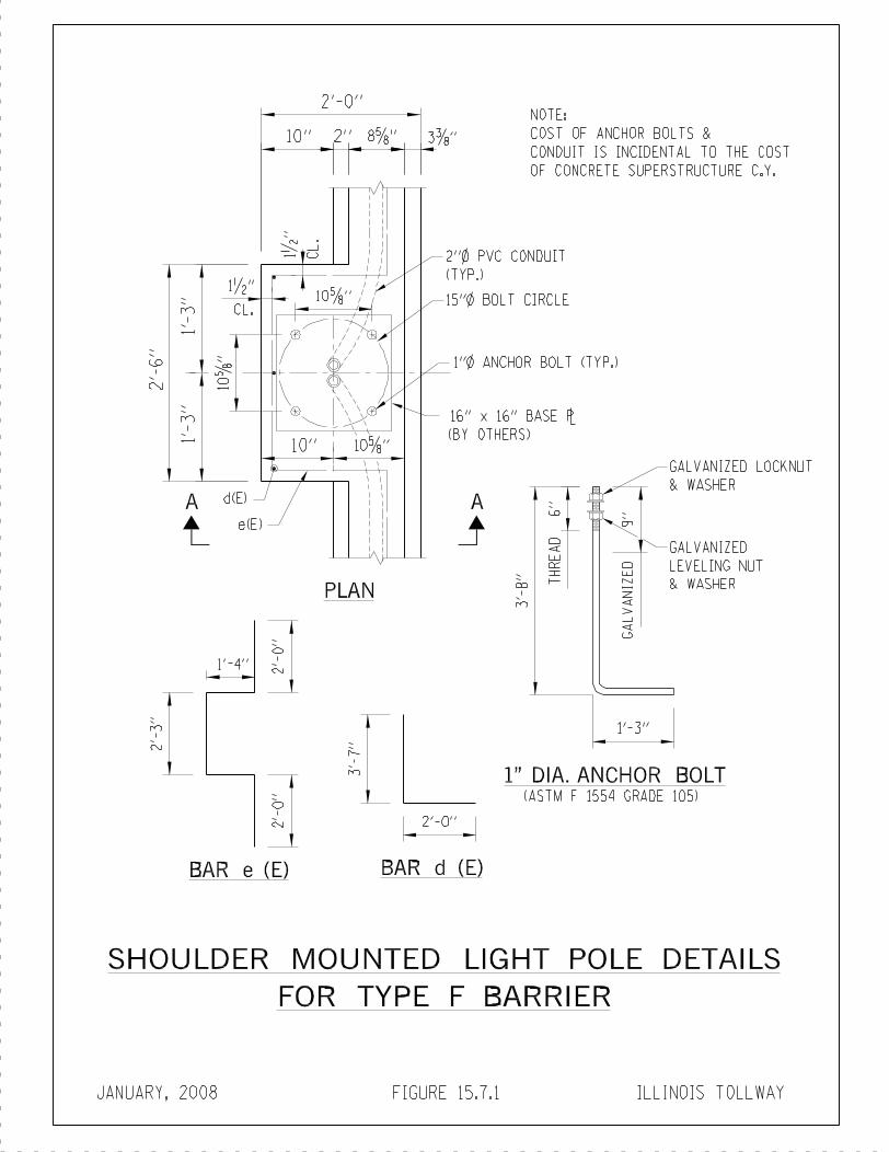


SECTION 16.0 DECK DRAINAGE
Bridge deck drainage shall be designed and detailed in accordance with the applicable portions of Chapters 7 and 8 of the latest IDOT Drainage Manual and Subsection 3.2.9 of the latest IDOT Bridge Manual, except as amended here in. The use of deck drains on Tollway structures shall be minimized or avoided whenever possible.
16.1 Deck Drains
When deck drains are necessary, decks shall be provided with uniformly spaced freefall floor drains wherever feasible. Floor drains may be angled if required to clear the beam or girder flange. Preference shall be given first to the use of 6 inch diameter fiberglass pipe or aluminum tube. If insufficient space exists between face-of-curb and the girder for a 6 inch diameter drain, consideration shall be given to the use of the 4” x 12” tube.
Floor drains shall be omitted from sections of the decks where the discharge would fall on underlying roadways, bikeways, walkways, railroads, aggregate slope paving or unprotected embankments, and other developed or highly erodible areas. Floor drains shall be located a minimum of 0.5 of the drop distance from the face of any abutment or pier. The drop distance is defined as the vertical distance between the bottom of the drain pipe and the top of the surface below. Drains shall be located clear of all diaphragms.
When floor drains are required by the drainage study, their locations and details will be shown in the Contract Plans following the bridge deck details.
16.2 Drainage Scuppers
If the drainage study indicates the need for scuppers, they shall be used exclusively. Only scuppers of grey cast iron will be acceptable unless a longer length requires the scupper to be fabricated from structural steel plate. Stainless steel hold down bolts meeting the requirements of ASTM F593, Type 304 shall be provided. The height at the spigot end of the scupper shall be increased from 7-1/4 inch to 12 inch to allow the flange connection to be made below the deck slab, with stainless steel bolts and nuts meeting requirements of ASTM F593 and F594, Type 304, respectively.
Deck drains and scuppers shall be located on the upstream side of bridge deck expansion joints whenever possible.
16.3 Drain Pipe
Wherever freefall drainage is not feasible, the drainage shall be piped to the ground or lower roadway. Pipes shall not be placed on the traffic face of barrier collision walls. Scuppers should be located directly above downspouts attached to the substructure. Midspan locations that would result in complex, lengthy piping should be avoided wherever possible. Where horizontal piping is required, horizontal runs shall be 8 inch in diameter. All downspouts shall also be 8 inch in diameter. Figures 16.3.1, 16.3.2, 16.3.7 and 16.3.8 illustrate drainage system details. Drainage piping shall be polyvinyl chloride (PVC) whenever possible.
Pipe hangers shall be provided on all horizontal collector pipes at each tee, elbow, or change in direction and at intermediate points not more than 5’-0” on centers. Collector pipe hangers shall have a load capacity of not less than 500 lbs. and shall be designed so as not to apply
January 2008 16-1 Illinois Tollway

excessive compressive stress to the pipe. Pipe supports shall be provided on all vertical drain pipes at points not more than 12’-0” on centers. See Figures 16.3.3 through 16.3.6 for collector pipe hangers, drain pipe support details, and expansion collar detail. All pipe hangers, supports and hardware shall be hot-dipped galvanized in accordance with AASHTO M232 (ASTM A153) unless otherwise noted. All bolts, nuts and washers shall be stainless steel. Stainless steel bolts shall conform to the requirements of ASTM A 193M (A193), Class 1, ASTM F593, TYPE 304 Grade B8. Stainless steel nuts shall conform to the requirements of AASHTO M 292, ASTM F594, TYPE 304 Grade 8 or 8F, and the washers shall conform to ASTM A 240, Type 302 or 304.
16.4 Painting
All floor drains, hangers, brackets and piping shall be painted. The color of the final coat shall match that of the adjacent beam and/or column, Munsell numbers 7.5G4/8 Interstate Green or 10Y7/1 Light Grey.
16.4.1
16.4.2
16.4.3
16.4.4
Aluminum Tube
The exterior surfaces shall be cleaned and given wash coat pretreatment in accordance with SSPC - SP1 and SSPC - Paint 27. The pretreated surfaces shall be painted with an adhesion bonding primer and top coat per the system specified for new structural steel in the latest IDOT Standard Specifications.
Fiberglass Pipe
The exterior surfaces shall be cleaned and given prewash in accordance with MIL - P - 15328. The prewash surfaces shall be painted with the system specified in the IDOT Pre-Qualified Products List for Painting of New Fiberglass Drainage Pipe.
PVC Pipe
All exterior surfaces of PVC pipe shall be painted with the system specified in the Pre-Qualified Products List for Painting of PVC Drainage Pipe.
Steel Pipe
All exterior surfaces of the steel pipe shall be painted with the standard three coat system specified for new structural steel in the latest IDOT Standard Specifications.
January 2008 16-2 Illinois Tollway


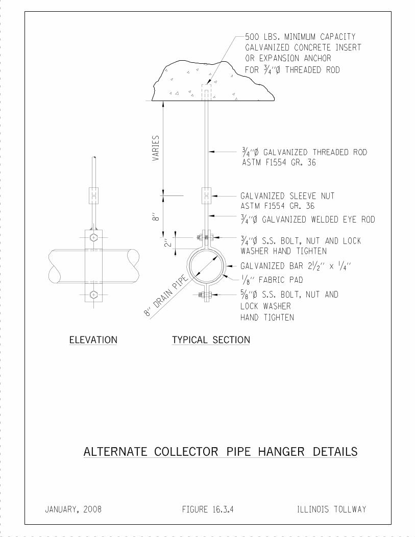
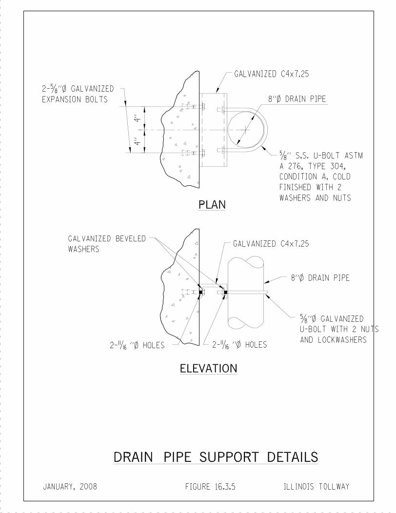


SECTION 17.0 BRIDGE DECK EXPANSION JOINTS
17.1 General
All new bridge deck expansion and fixed (rotational) joints shall be sealed to prevent water from penetrating to the bridge elements below the deck surface. Both expansion and fixed (rotational) joints will be designed and detailed in accordance with Section 3.6 of the latest IDOT Bridge Manual except as herein amended. Follow the manufacturer’s recommendations for the approved lengths and skews.
17.2 New or Replacement Bridge Decks
Three types of bridge deck joints shall be considered for use: the pressurized preformed joint seal, the strip seal joint and the modular joint.
Typical details for the pressurized preformed joint seal are shown in Figure 17.2.1.
Expansion and fixed joints installed on bridges with skews 10 deg. or greater shall be modified to intersect the barrier or curb line at 90 deg. This change in direction should occur within a range of 6 inches from the face of curb or barrier.
17.3 Existing Bridge Deck Widenings or Repairs
When a structure is widened, the new portion of the expansion or fixed joint shall match the existing portion at the same location unless that portion of the joint is in poor condition, in which case it shall be reconstructed as part of the widening. If the existing expansion joint armor or concrete nosing is in good condition, only the seal shall be replaced. Details for replacing deck expansion joints are shown in Figure 17.3.1.
When a structure is only being resurfaced and the existing joint is in poor condition, the joint shall be reconstructed and/or the seal replaced. If isolated sections of the existing joint armor or concrete nosing are damaged or deteriorated, they shall be reconstructed or repaired and the seal completely replaced between barrier rails.
When reconstructing expansion joints on existing bridges with skews greater than 10 deg., the joints shall be modified so they intersect the face of the barrier rail or curb at 90 deg. This modification typically consists of removing a short section of the existing barrier, and relocating the barrier joint so that the modified expansion joint intersects it at 90 deg.
17.4 Fabrication
All structural steel for expansion joints that shall be hot dipped galvanized after fabrication in accordance with the AASHTO M232 (ASTM A153).
January 2008 17-1 Illinois Tollway


SECTION 18.0 DECK ELEVATIONS
18.1 New Bridges
A table showing top of deck slab elevations along the centerline of each longitudinal beam or girder, bonded construction joint, break in cross slope, and profile grade line shall be included in the bridge plans for all structures with steel or concrete beams or girders. This table is usually in the form of a computer output reduced in tabular form on individual plan sheets. Examples of these sheets are shown in Figures 3.1.9-1 through 3.1.9-4 of the latest IDOT Bridge Manual.
In addition, top of approach pavement (slabs) elevations along each longitudinal profile grade line, break in cross slope, stage construction joint, edge of pavement and face of curb shall also be provided on separate individual plan sheet(s) after the deck elevation sheet(s). Examples of which are shown in Figures 3.1.9-5 and 3.1.9-6 of the latest IDOT Bridge Manual.
Where the beam or girder lies below a curb, sidewalk or median section, the elevations shall be given for a theoretical top of slab which would be the projection of the cross slope from the roadway template to the centerline of beam.
The increments for elevations along centerline of each web shall be 10 feet with any odd increment at the end of a span not greater than 15 feet or less than 5 feet. A new series of ten foot increments shall begin in each respective span along the structure. In all cases, the increments shall progress in the direction of the stationing on the bridge for the full length of the structure. The theoretical top of slab elevations at these increment points shall be adjusted for dead load deflection and tabulated in a separate column which will become the finished elevations for construction of the deck slab.
Actual dead load deflection (weight of concrete deck and all superimposed dead loads except future wearing surface) diagrams shall be shown on this sheet indicating deflection ordinates at the quarter points and mid point of all stringers of each span. However, if the variance in deflection between the exterior stringers and interior stringers is one-eighth inch or less, one dead load deflection diagram shall be sufficient for all stringers. Dead load deflection diagrams shall be qualified with the following note:
"The above deflections are not for use in the field if the Engineer is working from the Theoretical Grade Elevations Adjusted for Dead Load Deflection."
If the superstructure will be constructed in stages, any superimposed dead load applied during the initial stage shall only be distributed to a maximum of three stringers erected in that stage. The initial superimposed dead load will not be considered in the deflection calculations for stringers erected in subsequent stages.
18.2 Existing Bridge Deck Overlays
The procedure described below shall be used in the preparation of profile worksheets for bridge deck overlays and approach pavement profile transitions.
Profiles should be prepared for each edge of pavement and crown line. Where there is an auxiliary lane on the deck a profile for the edge of the auxiliary lane should also be prepared. The profiles should have a longitudinal scale of at least 1-inch equals 50 feet, and a vertical
January 2008 18-1 Illinois Tollway

scale of at least 1-inch equals 1-foot, although a vertical scale of 1-inch equals ½-foot will facilitate reading elevations from the profiles.
• Plot existing overlay surface elevations and existing concrete deck elevations at 20 foot centers on roadway and 10 foot centers on deck.
• Using 1-1/4-inch minimum latex concrete cover over the existing concrete high points and applying the cross-slope criteria as defined in Section 15.3, fit smooth curvilinear profiles following as close as possible the general direction and configuration of the original profile grade. Where scuppers are involved, cross sections should be drawn to verify that the scuppers will not present a problem.
• After the tentative profiles are sketched out, the cross-slope should be checked again for compliance with the criteria. More than one trial and error run may be required to achieve the best fit set of profiles for each individual deck. Profile lines should not follow theoretical grades and parabolic curves unless such grades and curbs happen to give the best fit for a particular location.
• The deck profiles should be transitioned back to the existing (or proposed) approach roadway elevation within 100 feet to 200 feet from each end of the deck. The transition should be long enough and end at the most convenient point as to provide a continuous smooth profile, without breaks, dips or bumps.
• Upon review and approval by the Tollway, the profile worksheets should be finalized with all lines neatly drawn and identified. It is intended that these worksheets will be used by the CM during construction.
• The elevations for the overlay surface contour plans or screed elevations may be scaled directly from the profiles developed from the field survey.
January 2008 18-2 Illinois Tollway

SECTION 19.0 APPROACH PAVEMENT (SLABS)
19.1 General
Bridge approach pavement (slabs) shall be included with the plans for each new and widened bridge. Mainline or ramp bridges carrying Tollway traffic shall be provided with approach pavement (slabs) including shoulders at each abutment. The approach pavement (slabs) shall be 100 feet long as detailed in the latest Tollway standard drawings G3 through G9.
Bridges carrying traffic other than that of the Tollway shall also be provided with approach pavement at each end of the structure. The approach pavement shall be 30 feet long as detailed in the latest IDOT Highway Standards.
Existing approach slabs and shoulders shall be widened, where required, in kind. The new expansion joints at the roadway end of the approach pavement (slab) shall match the existing joints unless they are in poor condition, in which case the existing joint shall be reconstructed as part of the approach pavement (slab) widening.
19.2 Approach Pavement (Slabs) for Tollway Bridges
19.2.1
19.2.2
19.2.3
Integral and Semi-Integral Abutments
The first 30 feet of approach slab is designed as a one-way slab simply supported on a 10 inch seat at the abutment end diaphragm and a grade beam at the other end. The next 70 feet is reinforced as a transition between the one-way slab and the roadway pavement.
The one-way slab shall be anchored to the bridge deck and end diaphragm with #5 reinforcing bars as shown in Figure 19.2.1.1. The joint between the bridge deck and the one-way slab shall be constructed without any expansion material. The top of this joint shall be tooled or sawed and sealed with hot poured low modulus polymer sealant. The other end shall be separated from the transition slab with an expansion joint located over the first grade beam as shown in Figure 19.2.1.1.
Vaulted Abutments
The first 30 feet of approach slab is designed as a one-way slab, simply supported on a 6 inch seat at the approach bent and a grade beam at the other end. The next 70 feet is reinforced as a transition between the one-way slab and the approach roadway pavement.
The one-way slab shall be anchored to the approach span with #5 reinforcing bars as shown in Figure 19.2.2.1. The joint between the approach span and the one way slab shall be constructed without any expansion material. The top of this joint shall be tooled or sawed and sealed with hot poured low modulus polymer sealant.
Pile Bent Abutments
The first 30 feet of approach slab is designed as a one way slab, simply supported on a 6 inch seat at the abutment and a grade beam at the other end. The next 70 feet is reinforced as a transition between the one way slab and the approach roadway pavement. Each end of the transition slab is supported on a grade beam.
January 2008 19-1 Illinois Tollway

The one way slab shall be anchored to the abutment per Sheet 3-241 of IDOT Bridge Manual and as shown in Figure 19.2.3.1. The joint between the abutment and the one way slab shall be constructed without any expansion material. The top of this joint shall be tooled or sawed and sealed with hot poured low modulus polymer sealant.
19.3 Approach Pavement for IDOT, County, Township or Municipal Structures
19.3.1
19.3.2
19.3.3
19.3.4
Integral and Semi - Integral Abutments
The approach pavement shall be detailed and anchored to the abutment per the IDOT Highway Standard 420401 and Subsection 3.8.3 of the latest IDOT Bridge Manual.
Vaulted Abutments
The approach pavement shall be detailed and anchored to the approach bent and span per IDOT Highway Standard 420401 and Subsection 3.8.9 of the latest IDOT Bridge Manual.
Pile Bent Abutments
The approach pavement shall be detailed and anchored to the abutment per IDOT Highway Standard 420401 and Section 3.8.5 of the latest IDOT Bridge Manual.
Approach Bent
All approach bents will be placed on piles in accordance with Figure 19.3.4.1. The grade beam used as a sleeper slab will no longer be used.
January 2008 19-2 Illinois Tollway


SECTION 20.0 SOIL BORING LOGS
The boring locations shall be shown on the plan view on the "General Plan and Elevation" sheet and keyed by a numbering system as described in the Geotechnical Engineer's Manual. The boring logs shall be included within the Final Plans and placed as the last sheets for each structure. Bottom of footings shall be indicated on the appropriate boring log and identified as "Bottom of Footing-Pier No.1, etc." Ground water elevations shown on the boring logs should state "Elevation at time boring was taken." An example Soil Boring Log is shown in Figure 20.1.
January 2008 20-1 Illinois Tollway


SECTION 21.0 CULVERTS
21.1 General
Culverts shall be designed in accordance with the latest AASHTO specifications and IDOT culvert manual, except as here in modified.
Box culverts are concrete conduits that must support vertical dead and live loads and lateral earth pressure. They may be single or multi-cell, box, three-sided box or three-sided arch sections constructed of cast-in-place or precast concrete. Culverts are most commonly used to carry water under roadways but they are also used for pedestrian/bicycle underpasses. The minimum size for a pedestrian/bicycle underpass is 10 feet high by 10 feet span. The minimum height for a hydraulic culvert is 5 feet. Typical sections for the most frequently used box culverts are shown in Figure 21.1.1.
Corrugated metal arch or box culverts are not permitted.
Hydraulic and geometric requirements of the site will determine the area and maximum height of the culvert. Once the maximum height and required area are determined, the selection of the type of culvert its construction and number of cells is determined by economics and site conditions. Barrel lengths are computed to the nearest 6 inch. The DSE shall determine the end of the barrel based on a barrier warrant analysis. For multi-cell culverts the cell widths shall be kept equal.
Wingwalls shall be designed according to the IDOT Culvert Manual. Horizontal Cantilever Wingwalls shall be used for wingwall lengths less than or equal to 14 feet. T Type or L-Type Vertical Cantilever Wingwalls will be used when the length of wingwall is greater than 14 feet. Reinforced concrete aprons between the wingwalls and safety end treatments shall be placed at both ends of the culvert, in accordance with the details shown in the latest Tollway Standard Drawings.
The barrel section of a culvert used for a pedestrian/bicycle under pass shall be covered with a waterproof membrane system in accordance with Section 581 of the Standard Specifications.
21.1.1 Cast-In-Place Concrete Culverts
The minimum cross sectional dimensions of a cast-in-place concrete box culvert are as follows and are increased in increments of ½ inch as required:
• Top Slab – Largest of the following: - 6 inch Minimum - By Design - Serviceability requirements of AASHTO Article 8.16.8 (z = 130 k/in)
• Bottom Slab: - Top Slab Thickness + 1 inch
• Sidewalls – Largest of the following: - 6” Minimum - By Design - 1 inch per foot of clear height "H”
January 2008 21-1 Illinois Tollway

- Sidewalls shall be designed for 40 Lb/cft equivalent fluid pressure for the fill from the top of pavement to the mid point of top of slab and 50 Lb/cft equivalent fluid pressure from mid point of top slab to mid point of bottom slab.
• Headwall: - Headwall design shall be in accordance with IDOT’s Culvert Manual.
In cases of long box culverts under high fills, it is recommended to reduce concrete thickness of the walls and slabs in areas of lower fill heights under the side slopes where economics indicate a substantial savings in material. This is generally accomplished by stepping or tapering down to thinner sections at practical intervals along the length of the culvert directly beneath the high end of shallower fill heights in the side slopes.
All reinforcement bars for box culverts shall be epoxy coated.
21.1.2
21.2.1 Organization
21.2.2
Precast Concrete Culverts
Precast concrete culverts are used where labor and materials are not readily available, and when the duplication and elimination of forms is more economical than the use of cast-in-place concrete culverts. Precast concrete culverts are not suitable in areas where the supporting soils are susceptible to excessive or differential settlements.
21.2 Plan Preparation
Plan sheets for culverts shall contain the following information:
The structure plan and elevation sheet shall include the following information: roadway alignment data, both horizontal and vertical; roadway and embankment slopes; station and elevation at the centerline of the culvert; culvert and wingwall lengths; invert elevations; barrel slope and flow direction; barrel section showing all concrete dimensions; headwall dimensions; general notes; index of sheets; bill of material; and location of soil borings.
If the culvert is to be constructed in stages, the plans must also clearly identify all stages of construction. Construction staging lines must be shown on all views. The staging plans shall also include the location and details of the temporary concrete barriers.
General Notes
The following general notes are required, when applicable, to supplement the Standard Specifications. While usually placed under the heading "General Notes", some notes may be placed near the associated detail. Additional notes shall be used, as required, to supplement the design of the culverts:
Cast-In-Place Concrete
• All Culvert concrete shall be Class SI.
• All exposed concrete edges shall have a ¾ inch x 45 deg. chamfer, except where shown otherwise. Chamfer on vertical edges shall be continued a minimum of one foot below finished ground level.
January 2008 21-2 Illinois Tollway

Reinforcement
• Reinforcement bars, including epoxy-coated reinforcement bars, shall conform to the requirements of AASHTO M-31 (ASTM A615), Grade 60, deformed bars.
• Reinforcement bars designated "(E)" shall be epoxy coated.
• Reinforcement bending details shall be in accordance with the latest "Manual of Standard Practice for Detailing Reinforced Concrete Structures", ACI 315.
• Reinforcement bar bending dimensions are out to out.
• Bars noted thus, 3X2-#5 indicates 3 lines of bars with 2 lengths of bars per line.
• Cover from face of concrete to face of reinforcement bars shall be 3 inches for surfaces cast against earth and 2 inches for all other surfaces unless otherwise shown.
• Reinforcement bars splices shall be in accordance with the following tables unless shown otherwise on the drawing.
Construction
• The Contractor shall not scale dimensions from the Contract Plans for construction. Scales shown are for information only.
• No construction joints except those shown on the plans will be allowed unless approved by the CM.
• The Contractor may request copies of existing construction plans that are currently on file with the Tollway. The request shall be in writing with the understanding that any reproduction cost will be at the Contractors’ expense.
• Non-Metallic water seal used in wingwall shall extend from the top of footing to within 6 inches of top of the headwall.
• It shall be the Contractor's responsibility to verify the location of all utilities prior to starting construction. Contact J.U.L.I.E., 800-892-0123.
• It shall be the Contractor’s responsibility to verify the location of all fiber optic utilities prior to starting construction. The Contractor shall initiate the locate process for the
Bar Splice - Barrel (Grade 60 Bars)
Size f′c = 3,500 PSI #4 1′ -4″ #5 1′ -8″ #6 2′ -0″ #7 2′ -9″ #8 3′ -8″ #9 4′ -7″
Bar Splice - Wingwalls (Grade 60 Bars)
Size f′c = 3,500 PSI #4 1′ -8″ #5 2′ -2″ #6 2′ -7″ #7 3′ -5″ #8 4′ -6″ #9 5′ -9″
January 2008 21-3 Illinois Tollway

fiber optic cable by completing a Request to Locate Tollway Facilities form (Tollway Form A-36) and submitting it to the Tollway. Copies of Form A-36 area available from the Tollway’s Utility/Permit Section (630-241-6800, ext 3306). Completed A-36 forms shall be faxed to the Tollway to the attention of Tollway Utility Administrator at 630-271-7568, at least four (4) business days prior to starting any underground operations, excavations or digging of any type in general area of the fiber optic cable.
• The Contractor shall use care when excavating around existing foundations. Any damage to the existing structure shall be repaired or replaced at the Contractor's expense.
• Existing reinforcement which is to be incorporated into the new construction shall be blast cleaned to grey metal, straightened (without heating), and cut to fit. Cost of which shall be included with that for “Concrete Removal.”
• Temporary soil retention systems, sheeting, bracing or cofferdams shall be constructed at the locations shown on the plans and/or as required for the excavation to protect the adjacent areas from settling or falling into the excavated areas.
• Plan dimensions and details relative to existing structure have been taken from existing plans and are subject to nominal construction variations. It shall be the Contractor's responsibility to verify such dimensions and details in the field and make necessary approved adjustments prior to construction or ordering of materials. Such variations shall not be cause for additional compensation for a change in the scope of work; however, the Contractor will be paid for the quantity actually furnished at the unit price for the work.
• At least 6 feet of the barrel shall be poured monolithically with horizontal cantilever wingwalls.
21.2.3
21.2.4
Bill of Material
Regardless of the placement of a coded “Summary of Quantities” on any other plan sheet. There shall be a “Total Bill of Material” shown in the plans for each box culvert.
Concrete Reinforcement
A Bar List shall be prepared for each culvert and shown along with bending diagrams of each bent bar on the appropriate plan sheet. See Figure 5.3.8.1 for the Bar List format.
In no case shall the same designation be used for reinforcement bars of a different size, length and shape when they are employed in other culverts. When detailing lengths of reinforcement bars, consideration must be given to transportation and handling and, where extremely long lengths are contemplated, to availability and special orders.
All sizes of bars are readily available in lengths up to 60 feet. However, sizes #3, #4, and #5 of more than 40 feet tend to bend in handling and should be avoided.
Bars shall be detailed to the nearest inch of length and the weight of reinforcement bars shown in the Bill of Material shall be to the nearest ten (10) pounds.
January 2008 21-4 Illinois Tollway

To provide uniformity on all culvert plans, bar designations used shall be as follows:
a – Top Slab (Transverse) b – Top Slab (Longitudinal) h – Barrel Walls and/or Wing Walls (Horizontal) n – Footing to Wall (Dowels) s – Stirrups t – Footing (Transverse) v – Barrel Walls and/or Wing Walls (Vertical) w – Footing (Longitudinal)
21.3 Design Criteria
21.3.1 Design Specifications
• AASHTO 2002 Standard Specifications for Highway Bridges and all subsequent interims
• AASHTO Materials Specifications M259 and M273 for precast concrete culverts
• The latest edition of the IDOT Culvert Manual
• IDOT 2007 Standard Specifications for Road and Bridge Construction and all subsequent revisions
• Tollway Supplemental Specifications to the IDOT Standard Specifications for Road and Bridge Construction
January 2008 21-5 Illinois Tollway


SECTION 22.0 RETAINING WALLS
22.1 Wall Types
Retaining wall structures are used to hold back soil or loose material where an abrupt change in ground elevation occurs. There are several types of retaining wall structures. Depending on the application, certain wall types are more advantageous than others.
• The DSE should generalize the site as being either a fill wall location or a cut wall location.
• A fill wall location is characterized by a substantial increase in the ground elevation behind the wall. Fill walls are also appropriate when excavation for the wall can be made without: disruption to traffic lanes that will not be replaced, the need for temporary soil retention or excessively steep or unsafe cut slopes.
• A cut wall location is characterized by a reduction in the ground elevation in front of the wall with minimal or no increase in ground elevation behind the wall.
Fill Walls Cut Walls
Cast-in-Place T-shaped or L-Shaped Soldier Pile Mechanically Stabilized Earth Sheet Pile Precast Modular Soil Nails Gabion Tangent Shaft
22.2 Retaining Wall Selection Process
For discussion of the retaining wall selection process, refer to Section 2.3.12 in the IDOT Bridge Manual.
The DSE must submit a feasibility study to the Tollway prior to preparation of TS&L plans. The purpose of the feasibility study is to select the most cost effective retaining system. As part of the feasibility study, the DSE should investigate a “no wall” option. This may often require additional right-of-way, earth work and/or relocation of existing utilities and existing structures. If the “no wall” option is not feasible, the DSE must study a combination of slopes and wall types to minimize the wall length and height, while remaining aesthetically acceptable and cost effective.
The feasibility study shall include the following items:
• Introduction – Discussion of the project and location of the retaining wall.
• Reason for Retaining Wall – Discussion of the improvement, adjacent property or structures and “no wall” option.
• Retaining Wall Criteria – Discussion of design loads, allowable soil pressures, site constraints and design requirements for the retaining wall.
• Retaining Wall Description – Discussion of the location, geometry and other physical features of the retaining wall.
January 2008 22-1 Illinois Tollway

• Structural Alternates – Description and cost estimate for each of the wall types investigated.
• Discussion and Recommendation – Summary of findings for each of the wall types along with a recommendation of which alternate to construct.
The feasibility study shall also include the following exhibits:
• Proposed alignment and roadway plan
• Proposed roadway cross sections
• Approximate general plan and elevation drawing
• Retaining wall typical sections
• Retaining wall cost estimates
• Soil boring location map
• Soil boring logs
22.3 Plan Sheet Organization
Each retaining wall shall consist of a set of sequentially numbered plan sheets. Plan sheets shall be organized in such a manner as to facilitate construction. The first sheet shall be a plan and elevation view of the entire wall showing the alignment of the wall and offsets to the roadway. The location of all lighting, signing, fencing, drainage structures and utilities located under, on adjacent to or passing through the wall shall be shown. Also, all design criteria shall be listed.
The TS&L and final plans shall include a true wall section(s) which shows wall offsets to control line(s) and R.O.W.
The second sheet shall contain an index of sheets, general notes, abbreviations, total bill of material, typical wall section and drainage details.
Subsequent sheets shall completely detail and dimension each succeeding section of the retaining wall in plan and elevation views. Separate bills of material, bar schedules, sections and details shall be included on each sheet. See Figures 22.3.1 through 22.3.8 for retaining wall details.
The final retaining wall plan set shall include pile driving record tables and boring log sheets for the data that pertains to the retaining wall. The bottom of footing elevation shall be shown on the appropriate boring log and identified as “Bottom of Retaining Wall Footing.”
22.4 Design Criteria
22.4.1 Design Specifications
• AASHTO 2002 Standard Specifications for Highway Bridges and all subsequent interims
January 2008 22-2 Illinois Tollway
• IDOT 2007 Standard Specifications for Road and Bridge Construction and all subsequent revisions
• Tollway Supplemental Specifications to the IDOT Standard Specifications for Road and Bridge Construction
22.4.2
22.4.3
Design Loads
• Dead Loads
Concrete = 150 lbs/cu. ft. Earth (E) = 120 lbs/cu. ft.
• Live Loads
Retaining walls built adjacent to the roadway shall be designed for live load surcharge pressure equal to but not less than 2’ of earth pressure according to the latest AASHTO Article 3.20.3.
• Earth Pressure
The formula to compute lateral earth pressure is by Coulomb's equation for the resultant parallel to the backfill slope. The angle of internal friction for granular material is ∅ = 30 deg.
The formula to compute lateral earth pressure for sloping backfill assumes the mass of earth behind the wall extending to the point of intersection of the two planes (slope plane and failure plane of soil). In many cases the sloping backfill ends at a certain height above the wall where a roadway is intersected. The formula gives conservative results for this case. See Figures 22.4.2.1 for details
• Wind Loads
A wind load on the parapet and/or noise abatement wall shall be applied to the exposed surface area in any direction.
Design Stresses
• Reinforced Concrete
f' c - Compressive Strength = 3,500psi
• Reinforcement
fy - Yield Strength (Grade 60) = 60,000 psi fs - Tension (Grade 60) = 24,000 psi
22.5 Cast-in-Place T-Shaped or L-Shaped Wall
Cast-in-place T-shaped and L-shaped walls shall be designed in accordance with the IDOT Bridge Manual except as amended herein.
January 2008 22-3 Illinois Tollway

22.5.1 Description
22.5.2 Stem
22.5.3 Footings
22.5.4
In general, the Tollway uses cantilever T-shaped retaining walls up to a height of 25 feet. For details of a T-shaped wall see Figures 22.5.1.1 thru 22.5.1.3. L-shaped walls may also be used for special cases.
Typically, a T-shaped wall is more economical than an L-shaped wall. An L-shaped wall is required in cases where the face of the wall is adjacent to an obstruction or property line.
The minimum thickness at the top of the stem is 12 inches. For stems requiring thickness greater than 12 inches at the base, batter is provided on the back face of the stem (the face in contact with the earth) in increments of ¼ inch per foot up to a maximum of ¾ inch per foot. The batter shall be held constant for the entire length of the retaining wall.
The bottom of footing depth shall be below the frost penetration depth, which is generally 4 feet below the top of finished grade. The minimum spread footing thickness of the T-shaped wall is 18 inches and is increased in increments of 3 inches. The spread footing thickness shall not be less than the stem thickness at the base plus 3 inches.
For pile supported footings on T-Type wingwalls, the minimum thickness shall be 1'-9" and the piles shall be embedded 12 inches. The front row(s) shall be battered if the piles' lateral resistance to sliding is not adequate. The maximum pile spacing shall be as specified in Section 3.10 of the IDOT Bridge Manual.
For walls with pile footings it is usually more economical to use the minimum width of footing where feasible rather than to increase the footing width to reduce the number of piles.
If the top of finished ground is sloped along the face of wall, a stepped footing should be considered. For details of a stepped footing see Figures 22.5.3.1 and 22.5.3.2.
Stability
For spread footings on soil, the vertical resultant must fall within the middle 1/3 of the footing width. For spread footings founded on rock, the vertical resultant must fall within the middle 1/2 of the footing width.
The safety factor against sliding shall be 1.5 or greater for spread footings.
Factors resisting sliding for:
• Spread Footings.
Friction between soil and concrete
For Clay: Resisting Force = (Unconfined compressive strength) * 0.5 For Sand: Resisting Force = W * Tan ∅
January 2008 22-4 Illinois Tollway

Where: W = Vertical Load ∅ = Internal Angle of Friction
Tan ∅ = 0.45 is a safe value
• Shear Key.
The purpose of shear keys is to mobilize the passive pressure of soil in front of shear key.
Place the shear key in line with the front face of the stem except under severe loading conditions.
The width of the shear key shall be 1’-0” minimum. The minimum key depth is 1’-0”. The design load on the shear key is the passive earth pressure.
The shear key is placed in unformed excavation against undisturbed material.
Friction between soil and soil in front of shear key – multiply vertical load times the friction factor (use 0.70 for sand).
• Spread footings on rock. Key the footing a minimum of 6” into the rock.
• Pile Footings.
Horizontal component of battered piles. Maximum batter is 3 inches per foot.
For the lateral resistance of battered or vertical piles, in addition to horizontal component of battered piles, consult the geotechnical report.
22.6 Mechanically Stabilized Earth (MSE) Retaining Wall
MSE walls shall be designed in accordance with the latest IDOT Bridge Manual except as amended herein.
22.6.1 Location
22.6.2
MSE wall should be located a minimum of 10'-0" inside of the Tollway's right of way. Ground reinforcing shall not extend under the Tollway shoulder, unless the height of a substitute conventional cast-in-place wall would be greater than 25'-0", in which case the MSE wall shall be used regardless of the location of the ground reinforcing.
Plans and Specifications
The Contractor shall be provided with plans showing a line diagram envelope of the proposed wall location, grades, and dimensions. Specifications shall be furnished covering the work requirements for design, construction plans, materials procurement, and wall construction. The prequalified retaining wall supplier selected by the Contractor must submit a complete set of design calculations, detailed plans, and explanatory notes for the DSE's review and approval prior to ordering any material. The design must be in accordance with Section 5 of the AASHTO Standard Specifications of Highway Bridges and the special provisions. All costs for
January 2008 22-5 Illinois Tollway

performing the work required by including necessary technical expertise shall be included in the price bid by the Contractor.
The DSE shall prepare plan sheets containing the following information:
• Site plan with boring locations
• Wall plan with stations and offsets
• Top of wall elevations (located at the top of exposed panel line)
• Top of ground elevations at front and back face of wall
• Safety-barrier railing, or fence requirements
• Special coping requirements
• Utility accommodations
• Drainage requirements
• All special design features
• Subsurface information (the proprietary wall companies must be informed of all geotechnical stability and settlement concerns)
• Wall surface textures
• Wall design criteria
• Minimum footing depth (generally 4'-0", which is considered to be the frost penetration depth)
22.6.3
22.6.4
Design Life
The required design life for ground reinforcement elements of MSE retaining wall structures is 75 years. A design life of 100 years is required for MSE bridge abutment walls.
Factors of Safety
Minimum "Factors of Safety" used for design shall be as follows: (see AASHTO Section 5 and the special provisions for definition of variables and for "Factors of Safety" not listed).
Design Factors Factors of Safety - Sliding 1.5 - Overturning 2.0 - Bearing (soil pressure on bottom of footing) 2.5 - Global (shear failure outside of soil reinforcement) 1.5
January 2008 22-6 Illinois Tollway

Design Factors Factors of Safety - Polymeric Soil Reinforcement (AASHTO 5.8.7.2)
FD 1.7 FC 1.3 FS 1.5
- Connection Strength to Wall Units Pullout resistance/design load 1.5 Pullout resistance @ ¾″ deformation/ design load 1.5
- Metallic Soil Reinforcement Pullout from soil @ 0.5″ deformation 1.5
22.6.5
22.7.1 Design
Coping, Barrier and Moment Slab
Dowel the moment slab to the PCC pavement at 2’-0” centers using 2’-6” long #6 dowel bars.
The top of the moment slab shall have a 1-inch deep sawed joint in line with the transverse joints in the pavement.
Provide expansion joints in the moment slab at PCC pavement expansion joint locations.
Provide expansion joints in the parapets to match expansion joints in the PCC pavement and the moment slab. (Note, the expansion joint PJS should be carried up into the parapet, as done at bridge expansion joints). The expansion joint shall be detailed as shown in Figure 22.6.5.
Provide full height parapet joints every 90 feet.
Provide partial height parapet joints (in the upper portion of the parapet) at 15 foot centers. These partial height joints should alternate between the ½ inch expansion joints and ¾ inch v-grooved construction joints.
22.7 Block Retaining Walls
Block retaining walls shall be designed in accordance with Subsection 3.11.1 of the latest IDOT Bridge Manual and the latest AASHTO Specifications except as amended herein.
When specifying a proprietary block retaining wall, the special provisions should state that the wall shall be built according to the manufacturer’s specifications. The manufacturer’s specifications generally need to be supplemented. Material specifications for backfill, leveling pad, drainage systems, fill for hollow blocks, geotextile fabrics or any other special requirements should be clearly stated in the special provisions.
Modular block retaining walls must be designed and sealed by the manufacturer’s Illinois Licensed Structural Engineer. The design shall be in compliance with the applicable portions of AASHTO Section 5 and the special provisions. Soil reinforcement shall be either galvanized or coated steel or polypropylene or polyester geogrids. In the absence of more accurate data, design loads on the wall shall be based on a non-cohesive material with an angle of internal friction of 34 deg. The minimum size of the concrete leveling pad shall be 6 inches deep by 12
January 2008 22-7 Illinois Tollway

inches wide. All steel components of a system shall be hot dipped galvanized in accordance with the AASHTO M111 (ASTM A123).
22.8 Soldier Pile Retaining Wall
Soldier pile walls shall be designed in accordance with Subsection 3.11.3 of the latest IDOT Bridge Manual except as amended herein. Timber lagging is not permitted as a facing material for permanent soldier pile walls.
22.9 Permanent Sheet Pile Retaining Wall
Permanent sheet pile retaining walls shall be designed in accordance with Subsection 3.11.4 of the latest IDOT Bridge Manual.
22.10 Soil Nailed and Other Specialized Wall Systems
Soil nailed and other specialized wall systems shall be designed in accordance with Subsection 3.11.6 of the latest IDOT Bridge Manual.
22.11 Temporary Soil Retention Systems
Temporary soil retention systems, including temporary sheet piling, wire-faced MSE walls, braced excavations and other temporary construction works shall be designed in accordance with the IDOT Bridge Manual.
January 2008 22-8 Illinois Tollway


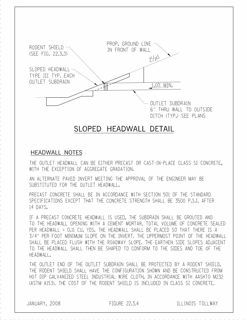


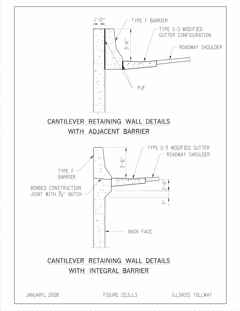


SECTION 23.0 NOISE ABATEMENT WALLS
23.1 General
Noise abatement walls shall be designed in accordance with the latest AASHTO Guide Specifications for Structural Design of Sound Barriers including all interims except as amended herein.
The Noise Abatement Wall shall be designed to attenuate the sounds generated by highway traffic and achieve a minimum noise reduction of 5 decibels.
The Noise Abatement Wall material shall be manufactured from fire retardant material that meets State and local requirements. Wood wall systems shall be used exclusively for noise walls mounted on structures (i.e., bridges and retaining walls). Ground mounted Noise Abatement Wall types shall be one of the following:
• Precast Concrete – The Precast Concrete Noise Abatement Wall shall consist of either separate panels, or posts and panels spanning between vertical posts. The precast concrete panels of the noise abatement wall may be conventionally reinforced, pre-stressed, post-tensioned, or any combination thereof. The posts of the noise abatement wall may be constructed of precast concrete or galvanized steel. If precast concrete posts are chosen, they may be conventionally reinforced, pre-stressed, post-tensioned, or any combination thereof.
• Concrete Masonry – This system consists of a noise abatement wall constructed of fabricated masonry block units. Masonry block walls shall be hand-laid. The posts of the noise abatement wall may be constructed of precast concrete, galvanized steel encased in masonry, or masonry block pilasters. If precast concrete posts are chosen, the posts may be conventionally reinforced, pre-stressed, post-tensioned, or any combination thereof. Concrete Masonry panels shall not be used as bridge or retaining wall mounted noise abatement walls.
• Brick Masonry – This system consists of a sound barrier constructed of fabricated brick masonry units. Brick masonry walls shall be hand-laid. The Brick Masonry Noise Abatement Wall shall consist of either separate panels, or posts and panels spanning between vertical posts. The posts of the Noise Abatement Wall may be constructed of precast concrete, galvanized steel, or brick masonry pilasters. If precast concrete posts are chosen, the posts may be conventionally reinforced, pre-stressed, post-tensioned, or any combination thereof. Brick Masonry panels shall not be used for bridge or retaining wall mounted or crashworthy ground mounted noise abatement walls.
• Composite – The Composite Noise Abatement Walls shall be a composite plastic extruded material. The Composite Noise Abatement Wall shall consist of separate panels, or posts and panels spanning between vertical posts. The posts of the Composite Noise Abatement Wall may be constructed of composite material, precast concrete or galvanized steel. If precast concrete is chosen, the posts may be conventionally reinforced, pre-stressed, post-tensioned, or any combination thereof.
January 2008 23-1 Illinois Tollway
• Wood – This system consists of a domestic or Canadian wood sound barrier constructed of treated wood posts, vertically oriented wood panels of tongue and groove construction, and a wood cap board to protect end grain.
• Alternate Material Noise Abatement Wall – This system allows the Contractor to bid an alternate material noise wall system that meets the requirements stated in this document and as approved by the Tollway.
The Noise Abatement Wall shall be designed for a minimum service life of 25 years based on the consideration of the potential long-term effects of weathering, corrosion, spray from de-icing chemicals, and other potentially deleterious environmental factors on each of the material components comprising the Noise Abatement Wall.
Expansion and Contraction Devices
The Noise Abatement Wall shall be designed with consideration of the movements in the wall due to temperature changes, dead loads and wind loads. Locations and spacing of expansion devices shall be as designed by the Contractor and reviewed by the Tollway.
Stabilizers
Permanent stabilizers are required between posts and panels to maintain the vertical positions of the panel while resisting the lateral loading primarily due to wind. The stabilizers shall be spaced at intervals not to exceed 4 feet, and shall be a minimum height of 4 inches.
23.2 Design Criteria
23.2.1
23.2.2
Design Specifications
• AASHTO 2002 Standard Specifications for Highway Bridges and all subsequent interims
• AASHTO 1989 Guide Specifications for Structural Design of Sound Barriers and all subsequent interims
• IDOT 2007 Standard Specifications for Road and Bridge Construction and all subsequent revisions
• Tollway Supplemental Specifications to the IDOT Standard Specifications for Road and Bridge Construction
Design Loads
All Loading and Geometric requirements as specified in the AASHTO Standard Specification shall be satisfied.
• Dead Load for wood noise walls mounted on bridges and retaining walls:
Maximum 20 psf of vertical wall surface
January 2008 23-2 Illinois Tollway

• Wind Loads
The minimum design wind load for bridge/structure mounted noise walls shall be 35 psf. For other noise walls, the minimum design wind load shall be 25 psf.
• Seismic Loads
In accordance with Subsection 1-2.1.3 of the AASHTO Guide Specifications for Structural Design of Sound Barriers.
The dead load shall consist of the weight of all the component materials making up the Noise Abatement Wall. For retaining wall and bridge mounted Noise Abatement Walls, the point of action of the weight of the individual components shall be their respective centers of gravity and the panel dead weight must not exceed 65 lbs/sq. ft. of panel face area.
Design horizontal pressures shall account for the direction of wind, height, and elevation of the wall, topography factors and gust factors. The Noise Abatement Wall shall be designed to withstand wind pressure, applied perpendicular to the wall and separately in each direction.
The maximum allowable panel deflection shall be no more than the panel length (L) divided by 240 (L/240) for ground-mounted panels and panel length (L) divided by 180 (L/180) for structure-mounted panels. L is equal to the length between panel supports. The vertical posts shall have a maximum deflection of (H/180) where H is the height of the post above the foundation.
Crashworthy walls located in the roadway clear zone shall be specifically identified in the plans and must meet the National Cooperative Highway Research Program (NCHRP) Report 350, “Recommended Procedures for the Safety Performance Evaluation of Highway Features.”
For ground-mounted crashworthy Noise Abatement Walls, a minimum point of impact load of 10 kips over 5 feet (2 kips/ft) must be used. If a Noise Abatement Wall is to account for lateral earth pressure due to unequal ground lines, that requirement shall be shown in the Plans.
23.2.3
23.2.4 Stresses
23.3.1 General
Design Height
The design height shall be determined by the DSE in conjunction with the noise mitigation study for each location.
Allowable design stresses for individual materials comprising the different wall types are covered in the Performance Based Special Provision for Noise Abatement Wall.
23.3 Plan Preparation
The DSE shall indicate the location of all required noise walls on the appropriate roadway and structure plans. Sufficient information shall be shown on the plans and cross sections so that the manufacturer can design and detail the noise wall to accommodate each; ground-to-structure transition, overlap, obstruction and utility or drainage interference. The DSE shall locate the beginning and end of the noise wall including overlaps and directional changes by
January 2008 23-3 Illinois Tollway

station and offset on the appropriate roadway drainage and lighting plans including cross sections. See Figures 23.3.1.1 and 23.3.2.4 for typical details.
An elevation view of each noise wall shall be included in the plans. Each elevation shall show top of noise wall and proposed grade. The location of transitions, overlaps, obstructions, utility or drainage interferences and changes in noise wall height shall also be shown. Changes in noise wall height shall be accomplished in 2 foot increments. The top of wall shall remain horizontal between steps. For an elevation view example, see Figures 23.3.1.2 and 23.3.1.3. Steps may be varied as long as wall remains above the Acoustical Profile Line.
23.3.2 Ground Mounted Noise Wall
For a typical roadway cut section, the ground mounted noise wall shall be constructed within a 5 foot wide zone. This zone shall be located adjacent to the proposed R.O.W. line wherever possible. See Figures 23.3.2.1 and 23.3.2.2 for examples. No utilities or roadway electric cable shall be located within the limits of the 5 foot wide zone.
For a typical roadway fill section, the centerline of the noise wall shall be placed no closer than 31 feet behind the proposed edge of pavement, provided the slopes between the gutter and the noise wall are no steeper than 6:1.
Overlapped sections of walls shall be separated by a minimum of 9 feet to provide access to the area behind the walls. A section of the wall shall be overlapped for a minimum length of four times the separation or gap distance. See Figure 23.3.2.3 for a typical section and plan. Overlaps shall also be located at ground to structure transitions. See Figure 23.3.2.4 for details.
Swales shall be provided on either side of the noise wall to collect and convey surface runoff to drainage ditches or field inlets. Field inlets shall be located at low points and connected to the side slope ditch or storm sewer. The DSE is responsible for designing and detailing all swales, ditches, field inlets and storm sewers on the drainage plans and profiles. Sheet flow shall not be allowed to flow under noise wall.
Foundations for Ground Mounted Noise Abatement Walls: The bottom of any foundation shall be a minimum of 4 feet below finished grade, unless solid competent rock strata is encountered. If a drilled foundation is used, it shall be a minimum of 6 feet below finished grade line or two times the shaft diameter, whichever is greater, unless solid competent rock strata is encountered.
Structure borings shall be taken at each end of the noise wall and every 100 feet thereafter along the proposed alignment. The boring locations shall be shown on the roadway plans and the resulting logs shall be plotted on full size sheets and included in the Plans.
Borings shall extend to a depth of twice the height of the wall below footing/proposed grade level, but not less than 15 feet. Borings shall extend at least 10 feet below compressible soils (N < 10 bpf, Qu < 1.0 tsf). If bedrock is encountered within the normal depth of the boring, at least half of the borings shall be cored to a depth of 10 feet into bedrock. If hard drilling (N > 60 bpf) is encountered at the termination of a boring to required depth, that boring shall be extended a minimum of 10 feet through such deposit.
January 2008 23-4 Illinois Tollway

23.3.3 Structure Mounted Noise Wall
The structure mounted noise wall shall be mounted on the back face of bridge parapets and retaining walls. See Figure 23.3.3.1 for example of mounting details. The type of material to be used shall be wood.
23.4 Specifications
The DSE shall modify the performance based special provisions furnished by the Tollway to suit their particular location and conditions.
January 2008 23-5 Illinois Tollway
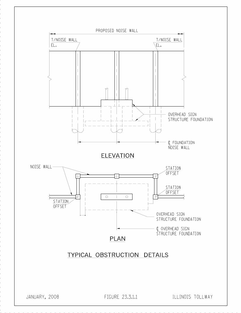


SECTION 24.0 OVERHEAD SIGN SUPPORTS
24.1 Design Specifications
• AASHTO 4th Edition 2001 Standard Specifications for Structural Supports for Highway Signs, Luminaires and Traffic Signals and all interims.
• The latest IDOT Sign Structures Manual.
• Tollway Standard Drawings, January 1, 2007, and all subsequent revisions.
• IDOT 2007 Standard Specifications for Road and Bridge Construction and all subsequent revisions.
• Tollway Supplemental Specifications to the IDOT Standard Specifications for Road and Bridge Construction.
• Allowable Stress Design Method shall be used to design or analyze overhead sign supports.
24.2 Overhead Sign Structure
Overhead Sign Structures shall be selected and detailed in accordance with the Tollway Standard Drawings, Section F.
24.3 Cantilever Sign Structures
Cantilever Sign Structures shall be selected and detailed in accordance with the Tollway Standard Drawings, Section F.
24.4 Bridge Mounted Sign Structures
Bridge Mounted Sign Structures shall be designed and detailed in accordance with the latest IDOT Sign Structures Manual.
In cases where the depth of the fascia beam is shallow and/or the profile grade approaches 5%, the location of the horizontal WF structure between the web of fascia beam and the back of the sign support may vary vertically in order to maintain the walkway in a level position (see Figure 24.4.1). Alternatively the location of the horizontal leg of sign support could also be varied to keep the walkway level (see Figure 24.4.2).
24.5 Dynamic Message Sign (DMS) Structures
Individual DMS or combinations of a DMS and one or more standard signs shall be supported by an IDOT Type III overhead sign truss. The size of the truss members will be based on the maximum span ranges shown in the latest IDOT Sign Structures Manual for Type III Trusses.
The face of any standard sign panel located on the same truss shall be mounted flush with that of the adjacent DMS by means of an offset. The DSE shall complete and include the latest IDOT base sheets for a Type III overhead truss supporting a DMS in the Contract plans.
January 2008 24-1 Illinois Tollway

The overhead sign truss will be supported by the standard IDOT 12” diameter leg assemblies for Type III truss. The DSE shall also complete and include the latest IDOT base sheets for 12” diameter legs and their corresponding foundations in the Contract plans. The foundations and/or their transitions may need to be modified to accommodate the Tollway standard barriers.
24.6 Overhead Sign Structures With Cantilever(s)
Overhead sign structures required to cantilever or overhang the supports at one or both ends shall utilize a standard IDOT (box) truss, support legs and foundations. The selected truss shall be analyzed for the proposed conditions and loads. The truss may be modified and redesigned (member sizes) if necessary to accommodate the proposed overhang(s) and sign(s) (see Figure 24.6.1). The DSE shall modify if required and complete the latest IDOT base sheets for the appropriate overhead truss, supports and foundations for inclusion in the Contract plans.
24.7 Non-Standard Sign Structures
Sign structures that do not fall within the criteria of the Tollway Standard Drawings or the latest IDOT Sign Structures Manual shall be designed in accordance with the latest AASHTO Standard Specifications for Structural Supports for Highway Signs, Luminaires and Traffic Signals.
The DSE must notify the Tollway in writing prior to beginning the design of a non-standard sign structure.
January 2008 24-2 Illinois Tollway

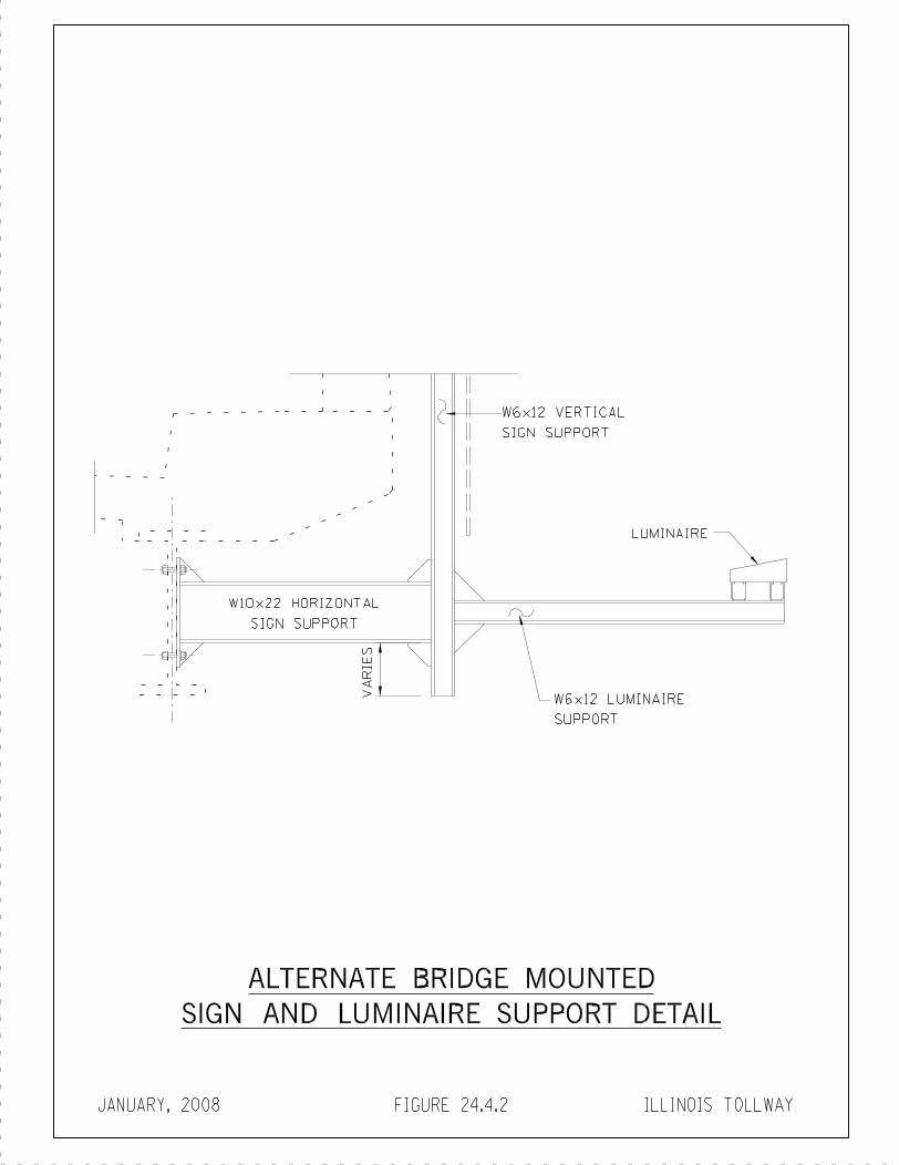


SECTION 25.0 SHOP DRAWINGS
25.1 General
Shop drawings are detailed fabrication and erection plans prepared by the fabricator, supplier or Contractor which are interpreted from the engineering drawings in the Contract plans. The DSE who prepares the engineering drawings shall be responsible for reviewing the corresponding shop drawings.
When reviewing shop drawings, it is not necessary to check the exact dimensions. It is the responsibility of the CM to ascertain that the fabricator is supplying the items specified while it is the Contractor’s responsibility that all items are fabricated to the correct dimensions. See Article 105.04(d) of the Tollway Supplemental Specifications.
25.2 Required Shop Drawings
Shop drawings are required for the following items:
Plate Girders Elastometric Bearings Wide Flange Beams Pot Bearing PPC Bulb–T Beams Fixed Bearings PPC I–Beams Anchor Rods PPC Deck Beams Pins and/or Link Plates Precast Concrete Box Culverts Precast Deck Planks Three Sided Precast Concrete Precast Fascia Panels Structures Precast Deck Forms Overhead Sign Structures Metal Deck Forms Cantilever Sign Structures Mechanically Stabilized Earth Walls Bridge Mounted Sign Structures Noise Walls Modular Expansion Joints Prefabricated Pedestrian/Bicycle Trusses Temporary Shoring, Jacking and Cribbing
Other project-specific items not included in this list may also require approved shop drawings.
25.2.1 Structural Steel, Bearings and Expansion Joints
Shop drawings shall be reviewed for the following items:
• Erection Diagram, showing general layout of the steel and marking scheme for identifying members.
• The number and size of all members.
• The details of all splices, showing the number, size and type of bolts, the type, size and length of all welds and a section showing the size of all splice materials.
• The details of all field connections, showing number, size and type of bolts, and the locations where reaming is required.
• The number, size and spacing of shear developers. The use of shop welded shear developers is acceptable.
January 2008 25-1 Illinois Tollway

• The amount and location of camber and the permissible tolerances.
• Bearing details showing size, type and materials.
• The ASTM designation of the steel to be fabricated.
• The steel surface preparation and the type of shop painting to be applied.
• All notes that appear on the design plans must be reflected on the shop drawings.
• Structural steel weights (shop bills) must be checked and should weight adjustments cited in the Standard Specifications for Construction.
• Blocking and lifting diagrams.
25.2.2
25.2.3 Bearings
Prestressed Concrete
Shop drawings for prestressed concrete elements shall be reviewed for the following items:
• Erection diagram, showing the general layout of the concrete elements.
• The number and size of all members.
• The number, size and type of prestressing strands or rods, and the forces in these prestressing elements.
• Bearing details showing size, type, and materials.
• The location and the details of lifting devices and of support points if the beam does not rest on its bearings while being transported,
• The location and type of any inserts required for attachments.
• The layout of the casting bed to be used for casting the prestressed beams.
• The location of hold-down devices for any draped strands.
• The location and length of any bond-breaker.
• The details and type of the reinforcing steel.
• All notes that appear on the design plans must be reflected on the shop drawings.
Shop drawings for fabricator designed bearings shall be reviewed for the following items:
• Location diagram, showing the general layout of the structure and the locations of the bearings.
• The number, size, and types of all bearings.
January 2008 25-2 Illinois Tollway

• The details of the bearings, showing all materials, dimensions, and welding.
• The steel surface preparation and shop coating details.
• Notes listing the material specifications for all parts of the bearings, and the design and specifications used for the design of the bearings.
25.3 Special Requirement Items
The Contractor and/or his supplier is responsible for designing and detailing the following items, which shall bear the seal and signature of an Illinois Licensed Professional Engineer or Structural Engineer, Shop drawings and computations shall be submitted for review and approval by the DSE. Approved shop drawings shall be archived with the as-built plans for each project.
• Mechanically Stabilized Earth (MSE), Retaining Wall, soldier pile and lagging Retaining Wall with facing and Sheet Pile and Tie-Back Retaining Wall with facing.
• Precast Concrete Box Culvert and Three Sided Structures.
• Seismic Isolation Bearings.
• Pedestrian/Bicycle Truss designs and shop drawings for structures crossing over a state or federal route, placed on Tollway right-of-way, or having spans 150 ft. or longer shall be submitted for review and approval. If these structures are constructed by another governmental unit (county, municipality, park district, IL Dept. of Natural Resources, etc.), that agency is responsible for the review and approval of the designs and drawings.
• Noise Walls including their foundations.
• “Stay-In-Place” Metal or Precast Concrete Deck Forms.
• Temporary Shoring, Jacking and Cribbing.
25.4 Shop Drawings
Shop Drawings for the following items need not be submitted for review unless specified or special (non-standard) details are proposed for routine items:
• Steel Bridge Rail, Aluminum Bridge Rail, Pedestrian/Bicycle Railing, Pre-Fabricated Inspection Platforms, Scuppers, Drain Piping, Navigation Lights and Mounting Hardware.
• The fabricator must furnish installation and detail drawings to the Contractor and CM for field verification of locations and dimensions. These drawings should be included in the project record. Shop fabrication inspection is not required, and the CM’s final acceptance may be based on proper fit and an overall visual inspection of the finished product.
• Standard design base sheet notes require permanent tubular steel bridge traffic rail and rail posts to have Charpy-Vee Notch (CVN) toughness values certified by test.
January 2008 25-3 Illinois Tollway

Test results, along with mill certification documentation, are to be submitted to the CM. CVN testing is not normally required for bicycle/pedestrian railing. All steel for railing, bolts, anchor bolts and posts must be domestic. Any paint used must be accepted by the IDOT Bureau of Materials and Physical Research (BMPR). Current requirements of the BMPR concerning aluminum rail and posts must be satisfied.
Bridge Joint Sealing System (Pressurized Preformed Joint Seal (PJS) or Strip Seal):
• These joints’ may be prefabricated in convenient lengths, allowing subsequent shop or field cutting to meet project requirements. Since details will be generic, no project-specific review is required. An installation scheme should be provided by the fabricator to the Contractor and CM.
Fabric Reinforced Elastometric Mats and/or steel anchor plates for the back of Integral Abutments:
• The fabricator must furnish installation and detail drawings to the Contractor and CM for field verification of locations and dimensions. These drawings should be included in the project record. Shop fabrication inspection is not required, and the CM’s final acceptance may be based on proper fit and an overall visual inspection of the finished product. The mat supplier is responsible for submitting samples to the BMPR for lot testing.
25.5 Erection Plan
25.5.1 General
25.5.2
The Contractor shall submit structural steel erection plan to the DSE for each structure in the Contract. This plan shall meet all the requirements of Article 105.04 (c) of the Tollway Supplemental Specifications. Copies shall be sent for comments to any railroad company or public agency affected by the proposed erection procedure. These plans must be received at least 30 days prior to the proposed beginning of erection. All comments or revisions required by the DSE, railroad company, or public agency shall be incorporated in the final submission, for review and comment by the DSE.
Required Information
The following minimum information shall be placed on the erection drawings for each individual structure. Erection procedures for twin bridges may be shown on the same sheet:
• Title block with contract number, design project number, project and structure name and county.
• Plan of the work area showing support structures, roads, railroad tracks, canals or streams, utilities or any other information relative to erection.
• Erection sequence for main members and secondary members (crossframes, diaphragms, lateral bracing, portals, etc.), noting use of holding cranes or temporary supports, falsework, and bents.
• Delivery location of each girder.
January 2008 25-4 Illinois Tollway

• Location of each crane for each pick.
• Capacity chart for each crane and boom length used in the work. Cranes lifting over active railroad facilities shall have a minimum lifting capacity of 150 percent of the lift weight.
• Pick point location(s) on each member.
• Lifting weight of each member (including clamps, spreader beams, etc.).
• Lift and setting radius for each pick (or maximum lift radius).
• Description of lifting devices or other connecting equipment.
• Girder tie down details or other method of stabilizing erected girders.
• Bolting requirements, including the minimum number of bolts and erection pins required to stabilize members during the erection sequence.
• Blocking details for stabilizing members supported on expansion bearings and on bearings that do not limit movement in the transverse direction.
• The method and location of temporary support for field spliced or curved girders, including shoring, falsework, holding cranes, guys, etc. The DSE will examine, but not approve details of temporary supports. The design, erection, and stability of these supports shall be the sole responsibility of the Contractor.
• Offsets necessary to adjust expansion bearings during erection to provide for temperature variance and dead load rotation.
The following notes shall be placed on the Erection Drawings:
• No crane will be operated in a manner that will exceed its rated capacity at any radius as specified by the crane manufacturer.
• The table or chart prepared by the crane manufacturer to describe the maximum lift at all conditions of loading shall be posted in each crane cab in clear view of the operator.
• The Contractor shall be responsible for verifying the weight of each lift and for insuring the stability of each member during all phases of erection.
• Members shall be subject to only light drifting to align holes. Any drifting that results distortion of the member or damage to the holes will be cause for rejection of the member.
• Field reaming of holes shall not be performed unless required by the Contract Documents or approved by the DSE.
• The final alignment and profile of the erected steel shall conform to the requirements of the Contract Documents. Measurements and elevations shall be taken to verify the requirements of the Contract.
January 2008 25-5 Illinois Tollway

SECTION 26.0 REHABILITATION AND REPAIR
26.1 General
When extensive repairs to a structural member appear necessary, to the extent that the structural capacity of the member during construction may be in doubt, provisions shall be made to temporarily support the member during construction. This also applies to concrete member repairs, whether it is pneumatically applied mortar or formed concrete repairs. The location of proposed temporary supports shall be indicated on the plans.
Refer to the latest edition of the “Structural Services Manual” by the IDOT Bureau of Bridges and Structures. The manual contains information and guidelines for the types of repairs most often required to adequately maintain typical bridge structures during the service life. The DSE and/or Contractor are encouraged to use guidelines provided in the above referenced manual in preparing final repair details associated with the rehabilitation project.
The most common types of repairs/rehabilitation tasks associated with Tollway projects are listed below, including applicable sections from the above referenced manual.
• Bridge Deck Overlay – Section 1.4
• Expansion Joint Replacement – Section 1.5
• Bridge Rails and Parapets – Section 1.7
• Bearing Replacement – Section 1.9
• Impact Repairs – Steel Beams – Section 1.13
• Impact Repairs – Concrete Beams – Section 1.14
• Steel Superstructure Repairs – Section 1.15
• Concrete Superstructure Repairs – Section 1.16
• Substructure Repairs – Section 1.17
26.2 Precast Concrete Repairs
Even though a higher quality of standards is maintained in a plant-cast prestressed concrete environment, damages or defects can still occur in such products. Examples include voids and cracks in concrete and improperly placed or damaged reinforcement and hardware. These products fall into one of the three following categories:
• Products that can be accepted without repair
• Products that can be accepted with repair
• Products that must be rejected
January 2008 26-1 Illinois Tollway

Refer to “Manual for the Evaluation and Repair of Precast, Prestressed Concrete Bridge Products” published by PCI. The Manual also addresses evaluation and repair for damage caused by imperfections or damage occurring during production, handling, transportation and erection. This Manual serves as a resource and a base for developing repair options. The DSE and/or Fabricator is required to prepare repair procedures and details using guidelines provided in the above referenced manual while applying sound engineering judgment. The repair procedures and details shall be submitted to the Tollway for review and approval.
26.3 Aluminum Sign Truss Repairs
Refer to Figures 26.3.1 through 26.3.4 regarding suggested details for repairing existing aluminum sign trusses. These details are to be used as guidelines in preparing repair plans for sign trusses. Figure 26.3.5 provides guidelines for installing damping devices for existing aluminum trusses.
26.4 Approach Slab Resurfacing And Repairs
When resurfacing an existing approach slab, the surface of new overlay shall be string lined to provide a smooth transition from the ends of bridge to the existing road.
Before resurfacing, the spalled areas of existing approach slabs will be repaired with partial depth concrete patches and completely deteriorated areas will be repaired with full depth patches. Reinforcement bars exposed in repair areas that show a 50% loss of section due to corrosion or that were damaged during concrete removal shall be supplemented with additional bars equal to the area of the original deteriorated or damaged bar(s) (see Figure 26.4.1).
Existing reinforcement bars that have been cut or damaged by the Contractor shall be provided with supplemental bars at no additional cost to the Tollway. Otherwise, supplementing corroded bars shall be paid for as “Reinforcing Bars” or “Reinforcing Bars, Epoxy Coated”.
Those areas of approach slabs showing settlement at the abutment backwall will be removed and replaced in accordance with the details shown in Figure 26.4.2. Existing preformed filler joints at the bridge end of approach slabs shall be replaced wherever possible with the detail shown in Figure 26.4.3.
26.5 Aggregate Slope Paving Repairs
See Figure 26.5.1 for suggested details for repairing eroded or damaged slope paving.
26.6 Metal Culvert Temporary Repairs
See Figures 26.6.1 through 26.6.4 for suggested details to temporarily repair metal arch or half round culverts until they can be programmed for replacement or lining.
26.7 Bearing Repairs
Frequently existing rocker bearings are found to be tilted and in need of adjustment. The magnitude of the adjustment is determined by comparing the measured horizontal displacement of the rocker with the theoretical displacement for similar temperature conditions. No adjustment is necessary unless the measured displacement exceeds the theoretical by ¾ inch or more. Adjustment is usually made by repositioning the sole plate; however, if a bearing stiffener is present, the stiffener should remain within the middle third of the repositioned sole plate.
January 2008 26-2 Illinois Tollway