rehabilitating history timber transportation structures at ... · rehabilitating historic timber...
TRANSCRIPT

Rehabilitating Historic Timber TransportationStructures At Burnt Cabins Grist Mill,Burnt Cabins, Pennsylvania
William J. Collins, Registered Landscape Architect, PrincipalSimone And Jaffe Incorporated, Landscape Architecture,Berwyn, Pennsylvania
AbstractBurnt Cabins Grist Mill is an operating, water-powered grist mill on Little Aughwick Creek inFulton County, Pennsylvania. The mill and ten acresof the privately owned site are listed on the NationalRegister of Historic Places. Two heritage timbertransportation structures were redesigned to combinetraditional timber construction techniques withmodern materials, treatment and constructionmethods, including:
1. a timber mill race flume; and2. a timber weigh station canopy and timber scale
bed.
The project was partially funded by the USDA ForestService Rural Development Program.
Keywords: Burnt Cabins Grist Mill, National HistoricRegister Site, Fulton County, USDA Forest Service,Southwestern Pennsylvania Heritage PreservationCommission, Mill Race
HistoryThe Village of Burnt Cabins enjoys a colorfultransportation history, in which the historic mill siteplays alocated
72
significant part. Burntin a narrow pass on
Cabins Grist Mill isthe western side of
Tuscarora Mountain, approximately three miles fromthe Pennsylvania Turnpike Tuscarora Tunnel. TheTuscarora ridge, and the pass through Burnt Cabins,were major Native American thoroughfares. Europeanmigration is first documented through Burnt Cabinsby Scottish-Irish immigrants traveling west fromMaryland.
Originally called Sidneysville, the name Burnt Cabinscomes from timber structures which early settlers hadbuilt upon land not yet purchased from the natives. In1750, the provisional governor ordered that thesecabins be burned in an attempt to appease the nativesand prevent bloodshed. White settlers soon returned.
Figure 1 - Location Map

Figure 2 - Burnt Cabins Grist Mill, West Elevation,
During the French and Indian War, the BritishGeneral John Forbes constructed his military roadover Tuscarora Mountain and through Burnt Cabins.He erected Fort Littleton (now a turnpike exit) fivemiles to the west. Tax records indicate that the firstgrist mill at Burnt Cabins was operating by 1770.Ruins of that first mill still remain to the east of theexisting mill, which was built in 1840.
“Vanderbuilt’s Folly,” the historic South PennRailroad, was to be aligned directly across the BurntCabins Grist Mill site. The railroad grade wascompleted to the west side of the Little Aughwick, butthe stream culvert was never constructed, nor was thegrade constructed at the mill site. This railroad right-of-way was purchased and partially used by thePennsylvania Turnpike Commission, which opened“America’s. First Superhighway” in 1940.
The new turnpike alignment bisected the grist millsite, isolating the mill pond from the mill, except for aculverted mill race under the raised highwayalignment. The final turnpike alignment miraculouslyspared the mill and most of the village from an earlier
1995 (Note: scale bed at lower left.)
plan to locate an interchange at the mill site. Thesection of Forbes Road through the mill site wasrerouted as Allens Valley Road, a state highway, andcut between the mill race and mountainside to passunder the turnpike.
Recent DevelopmentToday, Burnt Cabins Grist Mill has been identified asa “Heritage Gateway” into Fulton County and thesouthwestern Pennsylvania region. It is located alongRoute 522, on a portion of an auto tour route throughnine counties in southwestern Pennsylvania called the“Path of Progress” by the federal SouthwesternPennsylvania Heritage Preservation Commission(SPHPC.)
In 1994, SPHPC funded a master plan for the heritagepreservation and economic development of BurntCabins Grist Mill. Over the twenty five years prior tothis master plan study, owners Jack and SonjaBlattenberger had restored the mill and developed asuccessful gourmet mill products business. However,due to costs of historic reconstruction, many other
73
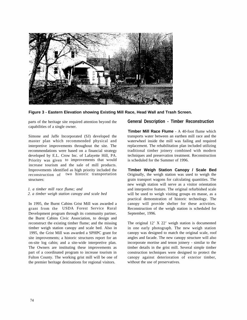
Figure 3 - Eastern Elevation showing Existing Mill Race, Head Wall and Trash Screen.
parts of the heritage site required attention beyond thecapabilities of a single owner.
Simone and Jaffe Incorporated (SJ) developed themaster plan which recommended physical andinterpretive improvements throughout the site. Therecommendations were based on a financial strategydeveloped by E.L. Crow Inc. of Lafayette Hill, PA.Priority was given to improvements that wouldincrease tourism and the sale of mill products.Improvements identified as high priority included thereconstruction of two historic transportation
structures:
1. a timber mill race flume; and2. a timber weigh station canopy and scale bed
In 1995, the Burnt Cabins Grist Mill was awarded agrant from the USDA Forest Service RuralDevelopment program through its community partner,the Burnt Cabins Civic Association, to design andreconstruct the existing timber flume; and the missingtimber weigh station canopy and scale bed. Also in1995, the Grist Mill was awarded a SPHPC grant forsite improvements; a historic structures report for anon-site log cabin; and a site-wide interpretive plan.The Owners are instituting these improvements aspart of a coordinated program to increase tourism inFulton County. The working grist mill will be one ofthe premier heritage destinations for regional visitors.
General Description - Timber Reconstruction
Timber Mill Race FIume - A 40-foot flume whichtransports water between an earthen mill race and thewaterwheel inside the mill was failing and requiredreplacement. The rehabilitation plan included utilizingtraditional timber joinery combined with moderntechniques and preservation treatment. Reconstructionis scheduled for the Summer of 1996.
Timber Weigh Station Canopy / Scale BedOriginally, the weigh station was used to weigh thegrain transport wagons for calculating quantities. Thenew weigh station will serve as a visitor orientationand interpretive feature. The original refurbished scalewill be used to weigh visiting groups en masse, as apractical demonstration of historic technology. Thecanopy will provide shelter for these activities.Reconstruction of the weigh station is scheduled forSeptember, 1996.
The original 12’ X 22’ weigh station is documentedin one early photograph. The new weigh stationcanopy was designed to match the original scale, roofangles and facade. The new canopy structure will alsoincorporate mortise and tenon joinery - similar to thetimber details in the grist mill. Several simple timberconstruction techniques were designed to protect thecanopy against deterioration of exterior timber,without the use of preservatives.
74

Figure 4 - Existing Timber Flume, Pedestrian Bridge, and Trash Screen.
originally set into an earthen embankment, almost
The existing timber scale bed was designed to bereplaced with treated timber.
1. Timber Mill Race Technical Details
This water transportation structure was constructedbetween a concrete headwall of the earthen mill raceand the stone mill foundation. The timber flume was
entirely below grade - except for the tops of the postsand headers, and the side of several bays on thedownhill side near the waste gate.
Original ConstructionThe existing timber mill race flume wasapproximately 40 feet long by 48 inches deep by 48inches wide on the inside. The flume was framed by aseries of rectangle bents which consisted of a sill, twoposts, and a header. The bents were traditionallyconstructed with mortise and tenon joinery andfastened with tapered wooden pins. By Summer of1995, about half of the original timber bents had beentemporarily repaired with pressure treated YellowPine.
Flume Bents - The new bents were redesigned to bevery similar to the original structure. All joinery wasdesigned to allow drainage. All joinery and pre-drilling was specified to be performed prior topreservative treatment to prevent perforation of theprotective treatment shell. Shaved white oak timberpegs were specified as bent fasteners. Tops of theheaders were sloped to prevent standing water anddiscourage their use as “balance beams.”
Figure 5 - Existing Timber Flume Bent Detail.
75

Flume Liner - The original trunk lining wasconstructed of tongue and groove boards nailedlongitudinally to the insides and bottom of the bents.The existing liner boards had been coated many timeswith tar to seal the wood and joints.
Flume Invert - The flume opening into the milldetermined the invert of the flume. The flume invertincluded a five inch curb which diverts water outthrough a waste gate to bypass the mill during periodswhen it is not in operation.
Concrete Headwall - The formed concreteheadwall includes flared upstream walls and a shortsection of concrete flume and apron. Most of theexisting headwall was in good condition, except forthe uphill wingwall which was cracked and heaving.
Control Gate - Between the parallel walls of theheadwall, a slot was formed to house a woodencontrol gate which is raised and lowered with verticalscrew rod to regulate the amount of water whichflows through the flume to the waterwheels.
Waste Gate - The waste gate is constructed in thedownhill side of the timber flume with openings in thetop and bottom of the wall boards in one bay near theconcrete headwall. The top opening is an overflow.The bottom opening is controlled with a simple boardon a stick which uses water pressure to hold the boardagainst the opening. The gate can be raised andlowered to adjust the flow of wastewater.
Trash Screens - The Owners have installed twowooden vertical-slatted trash screens within theexisting flume and headwall. These devices catchdebris before it enters the mill and require periodicraking to keep the flume open.
Required Demolition - The entire timber flumewas found to require demolition and replacement.One wing of the concrete headwall was cracked andshifted, and required removal and replacement. Theexisting overflow spillway was a series of deterioratedstone wall terraces stepping down to an overflowpond, which drains into the tail race. Demolition andreconstruction of these stone walls was incorporatedinto this project. Two wooden foot bridges over theflume were specified to be removed andreconstructed.
Figure 6 - Existing Timber Flume, Waste Gate and Stone Spillway.
7 6

Figure 7 - Plan - New Timber Flume and Spillway
Figure 8 - Section through new Timber Flume and Spillway
77

Structural Design Improvements - A system ofstructural concrete walls and slabs were designed asthe foundation for the new timber flume and spillway.The structure was designed to be hidden below gradeand to support an exposed native field stone facade.The design provided for surface and subsurfacedrainage from the uphill sides of the flume andretaining walls.
New timber bents were designed to sit on a new 4”reinforced concrete slab placed under the flumealignment between the headwall and mill foundation.The bents and structural liner were surrounded bygravel backfill to promote drainage and air movementaround the below-grade timbers. A porous geotextilefabric was specified to separate the gravel backfillfrom the earthen grade.
Two inch thick structural liner boards were designedto be nailed to the insides of the bents in thetraditional way, but not to hold water. Animpermeable liner was specified to be installedagainst the inside of the structural flume walls andfloor, as one piece, between the mill foundation andthe concrete headwall. A “facade” liner was designedas removable sections of longitudinal flooring andsiding on sleepers which cover and protect themembrane. The facade wall sections were designed towedge the floor sections in place without nailingthrough the membrane below the waterline. In fact,the membrane is employed to prevent leaks, not toprotect wooden members. The liner was designed tobe sealed to the concrete head wall with battens and tocontinue inside the mill to line the water distributionbox.
Waterproof Flume Liner - The waterproofmembrane liner was specified as a reinforced, 45 milpolypropylene polymer geomembrane with a non-woven polyester fiber geotextile bonded onto bothsides.
Species Selection and Preservative TreatmentRed Oak was selected for the structural liner and thebelow-grade bent members because it is a localhardwood which has an open cell structure capable ofaccepting preservative treatment. Untreated WhiteOak was specified as the bent headers because themembers will be above grade and in contact with thepublic; and the species has a natural resistance to rot.
as the optimum timber preservative for the below-grade members. Tar was specified as an on-site jointsealer.
Hardware - All hardware was specified to behot-dipped galvanized.
2. Weigh Station Technical Details
The previous weigh station canopy was a roofed,drive-through structure with portals under bothgables. The structure was asymmetrical with anenclosed shed section toward the north.
An existing iron scale carriage is mounted on aformed concrete foundation in a below grade well.The carriage is connected by a lever arm to the scalemechanism which is housed in an existing woodenstructure above grade.
Original Foundation - The tops of the concretewell walls are flush with the grade and areapproximately twelve inches thick. The originalcanopy posts were mounted directly into concretepiers located just outside these concrete foundationwalls. However, the existing concrete walls werechosen as the foundation for the new structure, toeliminate the need to construct new piers.
Canopy Structure Type - The original canopy wasused to protect grain wagons. The weigh stationcanopy was probably “stick” framed, however noevidence exists outside of an original photo. The newcanopy was designed to invite visitors, and protectthem from the elements during orientation to the mill.It could not exactly replicate the original design.
The new weigh station canopy was designed forobservation, as an open-sided timber frame with roof.The design includes mortise and tenon timber joinery,similar to the connections which exist inside the milland the mill residence.
Horizontal siding was specified on the gable ends toprotect roof members and cover knee braces, as sidingdid on the original structure. Siding exposure matchesthe mill siding.
New Post Details - The posts were designed to bearon standard metal post pedestals, to prevent the end
CCA-treated Yellow Pine was specified as the facadeliner and all control structures. Creosote was chosen
7 8

Figure 9 - Previous Weigh Station Canopy (date unknown.)
grain from directly contacting masonry. Posts weredesigined to be anchored by new threaded anchor rodsdrilled and grouted into the existing concretefoundation. Posts were designed to be drilled from thebottom to allow the anchor rods to be secured with atypical “bedpost” detail. A mortise opening for theanchor washer and nut was designed into the outsideface of the post. All outside faces of posts weredesigned with a protective one inch vertical sheathing,which extends as a drip edge below the bottom of theposts.
Bent Construction - The structure design employstypical “bents” which are post, girt, rafter, and braceassemblies, connected with mortise and tenon joineryand fastened with timber pegs or “pins.” Bents aretypically assembled on the ground and lifted to theirvertical positions. Connecting girts or “beams”connect the bents. The new canopy design employsfour bents - creating three “bays” between the bents.
The bay sizes were determined by the existingconcrete foundation which is asymmetrical. Astructure of this length could be built with only threebents, however a fourth bent was added to allow the
two center bent rafters to extend as an outrigger rooffor protection over the housed scale mechanism.
The bents at both gable ends were designed in theoriginal fashion with knee braces inside the portalopenings, and sheathed with horizontal siding. Studsbetween the bent girts and rafters were framed on twofoot centers to carry the siding.
The two interior bents were designed with triangularbracing in the roof trusses between the bent girt andrafters. Standard knee braces below the girts were notused on the interior bents to maintain the sense of oneundivided space. The outrigger roof does employknee braces outside the structure, between the postsand rafters.
Roof Overhangs - The roof includes substantialoverhangs on the sides and gable ends which aredesigned to protect the structure and space under theroof from normal, but not occasional driving rains,The side overhang drip lines are two and a half feetfrom the outside of the posts and we designed to helpshade and direct rain and snow away from the posts.
Purlins span longitudinally between rafters, and weredesigned to mortise into, but sit two inches above therafter tops to create airspace under the roofing, The
79

gable end overhangs were designed to use outriggerpurlins to extend the drip line of the roof twelveinches beyond the face of the portal.
Interpretive Features - The new weigh stationitself will be the subject of interpretation for visitors.It will serve visually as a major structure at the entryto the mill from the west. A dated commemorativeplaque will be mounted in each gable. The easternportal will serve as the visitor entry.
A structural railing was designed between bents tocontrol pedestrian movement and to supportinterpretive display panels. The display panels will beweatherproofed and mounted at an angle against thisrailing. Lighting inside the structure will be availableby running an underground conduit through a channelmilled in the outside of one post.
Self Draining Joinery - All joints which are notcovered by siding or roofing are designed to be selfdraining. This is accomplished by sloping normallyhorizontal mortise surfaces, and installing “weep”holes. These typical details are employed in the kneebraces and railing joints.
Species Selection - White oak was selected as theprimary local hardwood species for all canopystructural members because of strength and naturalresistance to rot. Siding was designed to be WesternRed Cedar.
Timber Treatment - The timbers in the weighstation canopy were designed for use withoutpreservative treatment. The plan includes painting theentire structure the same color as the mill.
Scale Bed - The existing timber scale bed was rottenand cordoned off from the public. Before demolition,sizes of existing members were documented. Thenew scale bed was designed using the originalmember sizes.
The timber bed structure was designed to bear on thethree longitudinal steel I-beams of the existing scalecarriage, each measuring 12 1/2” deep x 5” wide.Timber transverse beams measuring 6” deep x 8”wide spanned the three carriage beams at 16” centers.Longitudinal sleepers measuring 2” deep x 5” or 4”wide were used to span the transverse beams asnailers for the decking. Three inch thick transversedecking was used at random widths between 7” to12”.
Figure 10 - Existing Scale Bed (view to east.)
80

The original 1 1/2” space was left between the steeledge on the concrete foundation and the outsideedge of the scale bed deck. A 4” x 2 1/4” curbingwas designed to fasten to both sides of the deck with4” hex head lag bolts and washers as in the originaldeck.
All replacement deck members were specified ascreosote treated red oak, except for the deck andcurb timbers which were specified as CCA-treatedSouthern Yellow Pine.
Scale housing - The wooden scale housingmeasures 58” high x 62” long x 12” wide andrequires only minor repairs to the southern sill andvertical siding.
Two inch thick decking boards were specified to bereplaced between the bed and the scale housing with2” CCA treated Southern Yellow Pine.
PROJECT SIGNIFICANCE
The significance of the Burnt Cabins Grist Millproject promotes a wider recognition of “non-bridge” heritage timber transportation structures.The Weigh Station and Timber Flume are part of acomprehensive federal/local rehabilitation plan in ahighly visible, historic context.
The projects integrate local timber use, historictimber detailing and craftsmanship, and modemtimber treatment.
Information about these heritage recreationstructures will be part of a comprehensiveinterpretive plan for the entire historic visitors' site.The traditional canopy frame raising for the weighstation will be video documented for interpretivedisplays during mill tours.
AcknowledgmentsThe author would like to acknowledge John andSonja Blattenberger for their fine restoration andoperation of the Burnt Cabins Grist Mill. BurntCabins Civic Association. Marge Taylor, FultonCounty Economic Corp. John Bennett of SPHPC forfunding assistance. Lew USDA McCreery andMichael Rains of the USDA Forest Service forfunding assistance.
Figure 11 - Gable Elevation of New Weigh Station Canopy.
81