fmcw radar performance for atmospheric measurements
TRANSCRIPT

RADIOENGINEERING, VOL. 19, NO. 1, APRIL 2010 129
FMCW Radar Performance for Atmospheric Measurements
Turker INCE
Faculty of Computer Science, Izmir University of Economics, Izmir, Turkey
Abstract. Frequency-modulated continuous-wave radars (FMCW) have been used in the investigation of the atmosphere since the late 1960’s. FMCW radars provide tremendous sensitivity and spatial resolution compared to their pulsed counterparts and are therefore attractive for clear-air remote-sensing applications. However, these systems have some disadvantages and performance limitations that have prevented their widespread use by the atmospheric science community. In this study, system performance of atmospheric FMCW radar is analyzed and some measurement limitations for atmospheric targets are discussed. The effects of Doppler velocities and spectral widths on radar performance, radar’s near-field operation, and parallax errors for two-antenna radar systems are considered. Experimental data collected by the high-resolution atmospheric FMCW radar is used to illustrate typical performance qualitatively based on morphological backscattered power information. A post-processing based on single-lag covariance differences between the Bragg and Rayleigh echo is applied to estimate clear-air component from refractive index turbulence and perform quantitative analysis of FMCW radar reflectivity from atmospheric targets.
Keywords Electromagnetic measurements, remote sensing, instruments and techniques.
1. Introduction At low microwave frequencies, radars respond to
spatial variations in the index of refraction of the air often characterized by the atmospheric refractive-index structure function parameter, Cn
2. While remote measurement of the atmospheric boundary layer (ABL) is complicated by the low radar reflectivity of clear-air turbulence structures, FMCW radars, having tremendous sensitivity and spatial resolution compared to their pulsed counterparts, have proven to be a solution to this problem. While Doppler capability can be added to FMCW radars [1], the unique strength of this technology lies in its ability to monitor the
atmospheric refractive-index structure function parameter, Cn
2, with unparalleled resolution in height and time. Since the first high-resolution atmospheric FMCW radar, developed in 1969 by Richter [2], a number of FMCW radars have been developed for high-resolution atmospheric probing [3]-[5], which have provided valuable information about the fine structure and dynamics of clear-air turbulence. The advent of S-band, FMCW radars has opened a new research field, which was reviewed by Gossard [6].
Despite FMCW radars being excellent tools for turbulence studies in the convective ABL and in the capping inversion region [4], relatively few atmospheric studies reported in the literature have used FMCW radar data extensively for both quantitative and qualitative analysis of clear-air features observed. While S-band FMCW radars have been designed with the capability to obtain height and time resolutions of 1 m and 1 s, res-pectively, the degree to which these resolution limits are obtained in practice depends upon the properties of the atmospheric echo itself. Range measurement errors due to non-zero Doppler velocities and finite coherence of the clear-air echo have implications on both spatial resolution and Doppler estimation of FMCW radars. Although the theoretical background for FMCW radars is well established, their measurement limitations for atmospheric targets and performance impact for atmospheric ap-plications has received little attention in the literature.
A detailed review of the theory of operation of S-band FMCW radar and its application to atmospheric boundary layer profiling can be found in [7]. In earlier work [8], performance limitations of an atmospheric FMCW radar are illustrated with initial results. In this paper, first theoretical performance analysis of an atmospheric FMCW radar including the effects of range-Doppler ambiguity, parallax typical for two-antenna radar systems, and near-field operation are discussed. A typical system performance is then illustrated with data collected during field experiments by the high-resolution S-band FMCW radar described in [7]. FMCW radar signatures of atmospheric targets detectable at S-band frequencies have been analyzed by using both qualitative morphological information and quantitative backscattered power information from clear-air refractive index turbulence.
130 T. INCE, FMCW RADAR PERFORMANCE FOR ATMOSPHERIC MEASUREMENTS
2. Principles Frequency-modulated, continuous-wave (FMCW) ra-
dars may be thought of as a limiting case of pulse-compression radar where the duty cycle of the transmitted waveform approaches 100%. They operate by transmitting a long, coded waveform of duration T and bandwidth B. The improvement factor they gain over pulsed radars of equivalent range resolution is given by the time-bandwidth product of the waveform BT, which is often referred to as the compression gain. In FMCW systems, this gain can be very large, exceeding 60 dB. While several types of frequency coding may be used to yield the bandwidth B, linear frequency modulation is the simplest and most commonly used method in atmospheric FMCW radars.
Consider an FMCW radar that transmits constant amplitude linear FM signal of the form
),)2/(exp()( 2tajjwtts T 2 T 2t (1)
where w is the radian frequency and a is the chirp rate in rad/s2. The echo from an atmospheric target is essentially a delayed, attenuated, and possibly Doppler-shifted replica of the transmitted signal. The echo is demodulated by mixing it with a portion of the transmitted signal and low-pass filtering the result. The resulting beat frequency for a point target at range R0, moving at radial velocity ur, is given by
02 2 4( ) r r
r
u R uf t f ft
c c
(2)
where is the electromagnetic wavelength and
TBaf /2/
is the chirp rate in Hz/s. Here, the first term represents the Doppler frequency shift, fD, due to radial motion, and the second term represents the shift due to the nominal range of the target, which is exploited primarily by the FMCW radar. The final term represents defocusing due to the dilation of the reflected signal’s bandwidth due to the dependence of Doppler frequency to carrier frequency. For lower atmospheric velocities, the effect of the last term on the bandwidth of the echo may be safely ignored. Thus, for the case of stationary radar and targets, the beat frequency is linearly proportional to range.
Signal processing of the echo usually involves matched filtering, which is most commonly implemented for all ranges simultaneously through spectral analysis via an FFT algorithm. In this case, the output of the matched filter, which gives the response of the linear FMCW radar to a moving point target, can be expressed as
0
0
sin /( )
/D
D
f T R R Ry R
f T R R R
(3)
where fD is the Doppler frequency, and R = c /(2B) is the expected range resolution for a transmitted bandwidth
TfB . It is worth noting that this result is equivalent to
an impulse response of linear FMCW radar.
For FMCW Doppler radar, Doppler information can be retrieved on a sweep-to-sweep basis by analyzing the sequence of echoes from a particular range, as discussed by Strauch et al. [1]. In this case, the sampling frequency is the reciprocal of the sweep period T, the Nyquist Doppler frequency is 1/2T, and resulting in an unambiguous Doppler velocity interval of |ur| ≤ / 4T assuming that range measurement errors due to Doppler can be ignored. Conventionally, two-dimensional FFT is performed on received signals to obtain range and Doppler frequency (velocity) spectrum.
For a bistatic FMCW radar, the received mean power from a distributed atmospheric target of uniform reflectivity for circularly symmetric Gaussian shape antenna patterns, is given by [9]
2 2
12 2512 ln 2
t t rPG G RP R
R
(4)
where Pt is the transmitted power, Gt and Gr are transmit and receive antenna gains, Θ1 is the one-way 3 dB beam-width, R is range resolution, and is radar wavelength. To better estimate from the measured echo power at the output of receiver, the radar system must be calibrated.
Since the fluctuating refractive index n depends linearly on fluctuations of temperature and water vapor mixing ratio, Wyngaard et al. [10] have shown that refractive index structure function parameter Cn
2 can be expressed in terms of the temperature (CT
2), water vapor (CQ
2), and joint CTQ structure function parameters as
22222 2 QTQTn CbabCCaC (5)
where the coefficients a and b depend on the wavelength and the nature of the radiation. Based on Tatarskii’s theory of electromagnetic wave propagation in a turbulent atmosphere [11] and Ottersten’s work in his 1969 landmark paper [12], clear-air radars can estimate Cn
2 from radar backscattered power within scattering volume. For Bragg scattering from refractive index fluctuations due to homogeneous, isotropic turbulence, is commonly related to Cn
2 by Ottersten’ well-known equation:
2 1/ 30.38 .nC (6)
This equation assumes that the Bragg wavenumber, kB = 4 / lies within the inertial subrange. Note that structure function parameters are defined as ensemble average, hence they vary smoothly in time and space. In practice, such averaging is performed over space or time assuming ergodicity. As the conditions for ergodic hypothesis are generally not met in atmospheric conditions, the radar estimated values of Cn
2 often have statistical scatter both temporally and spatially. In general,

RADIOENGINEERING, VOL. 19, NO. 1, APRIL 2010 131
microwave radar observations of the clear-air atmosphere consist of Bragg scattering from refractive index turbulence and Rayleigh scattering from particulates such as insects, dust, etc. Therefore, for S-band radars, Bragg scatter from clear air depends much less on the wavelength of the radar than that of Rayleigh scatter (-4 dependence) by such airborne particles.
3. Performance Analysis
3.1 Range and Doppler
FMCW radar performance characteristics, such as range-Doppler coupling, can be seen from analysis of (3), which is also ambiguity function for linear FMCW signal. The presence of both range and Doppler terms in the argument of the sinc function illustrates the effect of target motion on the radar’s ability to locate. Fig. 1 shows a typical two-dimensional time delay (range) – Doppler (velocity) ambiguity surface for a linear FMCW signal with time-bandwidth product of 103. As seen from Fig. 1, maximum unambiguous Doppler can be increased (by decreasing sweep period) at the expense of range ambiguity, or alternatively increasing maximum range results in Doppler ambiguity. By rearranging the terms in the argument in (3), the apparent range of the target can be expressed as Rapp = R0 – fDTR, where it is easy to see that range mislocation by one resolution cell occurs when fDT = 1, or ur = ± / 2T, which also corresponds to the Nyquist velocity interval for FMCW Doppler radar. Therefore, targets with unambiguously measured velocities are misregistered by no more than one half a resolution cell, or misregistration occurs when target velocities are aliased. For example, for an FMCW radar system operating at 3 GHz with a sweep time of 50 ms, targets with radial velocities within ±0.5 m/s are registered properly.
Additionally, the coherence of the atmospheric target during the sweep interval will limit range resolution of linear FMCW radar. For complex moving targets and for volume scattering, the coherence time (or the reciprocal of the Doppler spectral width) of the echo will limit resolution. A distribution of Doppler velocities observed over an integration time, T, will yield a distribution of apparent ranges. The resulting rms spread in range is determined by the transformation of the Doppler spectrum to the range domain using the relationship Rapp = R0 – fDTR,
R f T R (7)
where f is the Doppler spectral width of the echo. From this relation, it is apparent that range resolution and sensitivity are optimized by matching the sweep time to the reciprocal of the Doppler bandwidth of the echo. In this case, the range spreading is equal to the range resolution, and the entire Doppler spectrum is confined to one range
bin. No improvement in sensitivity or in resolution is achieved by increasing sweep time beyond this value, as the resulting echo simply spreads to adjacent range bins. To maximize resolution and sensitivity, it is desirable to make both bandwidth and sweep time as large as possible. The effective value of sweep time is however constrained by the coherence time of the atmospheric echo. For example, a sampling volume with rms radial velocity of 1 m/s has a spectral width of 20 Hz at 3 GHz implying a coherence time of approximately 50 ms.
Fig. 1. The ambiguity surface for a linear FMCW signal with
a time-bandwidth product of 103.
3.2 Parallax and Near-Field Operation
From the weather radar equation (4), the received mean power can be correctly estimated only if radar targets are in the far field of antenna, that is R > 2D2 / , where D is the diameter of the antenna. Additionally, for bistatic FMCW radar employing two spatially separated antennas, a correction of the received power is necessary at near ranges to account for the reduced beam overlap. For Gaussian shaped beams aligned with their axes in parallel, the antenna parallax function, or fractional beam overlap is given by [7],
2
2 21
exp 2 ln 2p
dC R
R
(8)
where d is the separation distance between transmit and receive antennas, and Θ1 is the one-way half-power beamwidth. Note that parallax results in an apparent reflectivity reduction and parallax error of backscattered power becomes significant within the radiating near-field of the antennas such that assumption of a far-field Gaussian beam pattern is not valid. It is also worth noting that the far-field criterion, Rf = 2D2 / is based on a con-servative specification of maximum phase error, significant effects on the shape of the main lobe are not evident until R ≈ Rf / 4 [13]. Based on the universal near-field reflec-tivity correction [14], 1 dB reduction in reflectivity at Rf / 4 is indicated, and at closer ranges (R < Rf / 4) near-field gain
132 T. INCE, FMCW RADAR PERFORMANCE FOR ATMOSPHERIC MEASUREMENTS
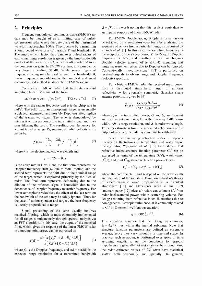
Fig. 2. S-band FMCW radar profiler image showing 23.5-hour record of the ABL during CASES-99 experiment on 26 October beginning at
14:27 CDT.
reduction becomes much more significant. Since at closer ranges the beam shape is no longer approximately Gaussian and is strongly dependent upon the particular antenna design, it is necessary to apply appropriate reflectivity correction for parallax and near-field gain reduction depending upon the parameters of radar system. Note that most atmospheric FMCW radars employ two spatially separated antennas because of the need for high isolation (~100 dB) between the transmitter and receiver. For the parameters of typical S-band systems, it can be shown that within the near-field range of the antennas, parallax has the dominant effect on reflectivity.
4. Experimental Results
Data collected by the University of Massachusetts’ high-resolution FMCW radar during recent field experiments is used to illustrate system performance and analyze radar signatures of atmospheric targets detectable at S-band frequencies. Detailed description of this system and data processing can be found in [7]. The S-band FMCW radar system implements an internal calibration loop to perform calibration of the atmospheric echo and estimate volume reflectivity. Fig. 2 shows one day continuous radar record of diurnal cycle of the ABL beginning at 14:27 local time (CDT, 19:27 UTC). The radar echo is expressed in terms of the logarithm of microwave Cn
2 obtained using (6), however, this representation is only meaningful for the clear-air component of the backscatter described by the Bragg scattering mechanism. In addition to distributed Bragg scatter from clear air, Fig. 2 shows strong point echoes, which are in this paper assumed to be entirely due to Rayleigh scatterers. It is worth noting that the distribution of Rayleigh scatter in reflectivity time-height image appears to reveal qualitatively additional boundary layer structure not otherwise detectable in S-band. However, the effect of much stronger Rayleigh echo (due to much stronger wavelength dependence, 4 as opposed to 1/3 for Bragg scattering) on quantitative backscattered power information is adverse. With high spatio-temporal
resolution capability of FMCW radar, by reducing time averaging to below 1 s in Fig. 2, it becomes possible to see undulations of O(10 m) in the radar echo as a consequence of Doppler-induced range measurement error due to the flapping of bird’s wings. It is estimated that vertical velocities of atmospheric echoes in general will contribute misregistration of about one range bin at most.
From Fig. 2, four-hour time period of convective ABL (between 14:30 to 18:30 local time) is extracted to perform quantitative analysis of radar reflectivity. In this case, the collocated radiosonde (operated by NCAR/ATD) measurements of temperature and humidity show typical characteristic of convective ABL bounded above by dry air. In the three panels of Fig. 3 respectively reflectivity, Doppler (vertical) velocity, and the correlation coefficient of successive echoes for one-hour of convective ABL are shown. The latter two products are the result of the pulse-pair processing [9] averaged over 20 pulses (~1 s averag-ing). The reflectivity image shows that initially significant Rayleigh backscatter is observed both above and below the capping inversion which peaks near 1000 m altitude at about 17:00 local time. After this time, both the Rayleigh scatter and the distributed Bragg scatter below the inver-sion decrease significantly, and the strong echo at the top of the boundary layer disappears. The velocity image which is derived from the phase of the single-lag covari-ance shows structure for some, but not all of the clear-air echo (due to velocity aliasing). The single-lag covariance panel shows very high (near unity) correlations for the Rayleigh scattering while the correlation coefficient for the Bragg scattering is relatively lower on average (due to larger spectral width of clear-air echo).
The fine space-time resolution capability of the FMCW radar enables isolation of Rayleigh scatterers from distributed Bragg scattering. To discriminate the dis-tributed Bragg backscatter from particulate scatter, a post-processing method based on the correlation coefficient between successive sweeps (averaged over the 1 s interval) is applied to time-series of backscattered power. As shown from analysis of single-lag correlation coefficient (in Fig. 3), the correlations for isolated particulate backscatter are significantly higher than those for distributed clear-air

RADIOENGINEERING, VOL. 19, NO. 1, APRIL 2010 133
Fig. 3. First hour of convective ABL echo from Fig. 2 showing reflectivity, Doppler velocity, and single-lag correlation coefficient.
backscatter. According to this method, magnitude of the sweep-to-sweep correlation coefficient is compared to an empirically determined threshold and high-correlation points (due to Rayleigh scatter) are removed. After some experimentation on the reflectivity data, a fixed threshold of 0.8 is found to be the appropriate choice since a much higher or lower threshold results in an increase in the probability of false alarm. The removed isolated point target echoes are then filled with the best estimates using the least-squares estimation which uses neighboring Bragg backscatter points without significantly affecting the statistics of the atmospheric clear-air echo [15]. This processing allows estimation of atmospheric component of the clear air backscatter. In Fig. 4, the computed vertical profiles of mean Cn
2 (estimated from postprocessed reflectivity) for four consecutive 60-min segments are plotted against height. The small dotted profiles show the corresponding mean reflectivity over the same intervals including both Bragg and Rayleigh echo. Given the mean horizontal winds, the vertical profiles are roughly equivalent to a streamwise spatial average over approx-imately 10 km. The vertical axis of each profile is scaled by the boundary layer depth, zi which can simply be obtained from the postprocessed reflectivity peak.
In this case, FMCW radar estimates of Cn2 can be
used to quantitatively test theoretical predictions on the ABL. In the free-convection boundary layer, Cn
2 is expected to follow a z4/3 power law, where z is the height above ground level [16]. From Fig. 4, radar estimated Cn
2 increases with height inside convective mixed layer (between 0.2 zi and 0.9 zi the mean reflectivity follows a z2/3 profile, a discrepancy of z2) with an expected sharp turbulence induced peak at the top of the mixed layer (~zi). Note in this case strong ground clutter affects Cn
2 measurements below 0.1 zi. This observed discrepancy in Cn
2 from its mixed-layer prediction may be due to entrainment effects, which can be predicted by a model developed by Fairall [17] based on a top-down and bottom-up diffusion approach in the entraining, convective boundary layer. According to Fairall’s model, the structure function parameter profiles for the convective boundary layer in the region 0.1 < z / zi < 0.9 can be expressed as
2 2/3 2( / ) ( / ) ( / )c i b i c tb i c t iC z h z z R h z z R h z z (9)
where
,)/()/( 3/4 icib zzAzzh
134 T. INCE, FMCW RADAR PERFORMANCE FOR ATMOSPHERIC MEASUREMENTS
Fig. 4. Vertical profiles of estimated mean Cn
2 (large data points) obtained from post-processing over four consecutive 60-min periods. The small dotted profiles show the mean reflectivity including both Bragg and Rayleigh echo. The dashed lines are normalized profiles of Cn
2 based on the Fairall’s model with specific Rc and Ac values.
,)/(57.0/115.2)/( 2/11 iiitb zzzzzzh
2( / ) 7 2.15( / )(1 / ) ,t i i ih z z z z z z
and c is temperature (T) or water vapor (Q). In Fig. 4, by choosing appropriate values for Rc and Ac parameters (respectively top-down and bottom-up components) of the model, the predicted normalized Cn
2 profiles is fitted to the vertical profiles of mean reflectivity from experimental data.
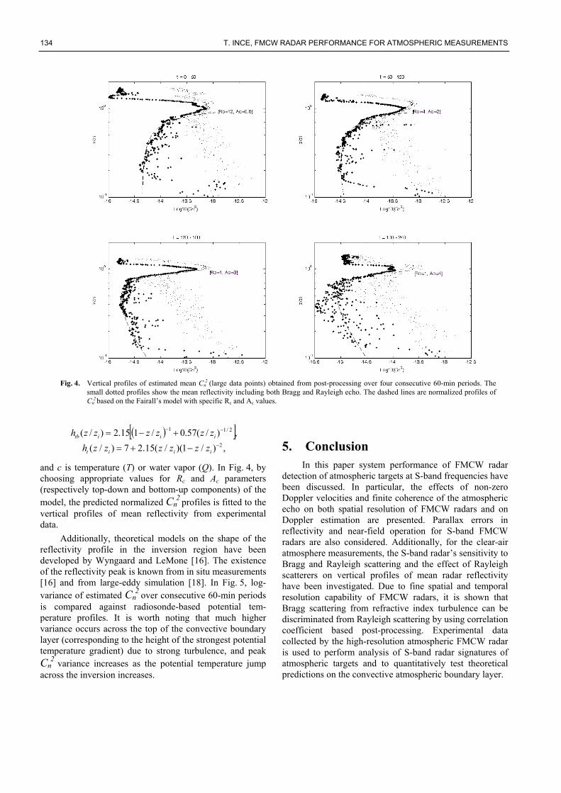
Additionally, theoretical models on the shape of the reflectivity profile in the inversion region have been developed by Wyngaard and LeMone [16]. The existence of the reflectivity peak is known from in situ measurements [16] and from large-eddy simulation [18]. In Fig. 5, log-variance of estimated Cn
2 over consecutive 60-min periods is compared against radiosonde-based potential tem-perature profiles. It is worth noting that much higher variance occurs across the top of the convective boundary layer (corresponding to the height of the strongest potential temperature gradient) due to strong turbulence, and peak Cn
2 variance increases as the potential temperature jump across the inversion increases.
5. Conclusion In this paper system performance of FMCW radar
detection of atmospheric targets at S-band frequencies have been discussed. In particular, the effects of non-zero Doppler velocities and finite coherence of the atmospheric echo on both spatial resolution of FMCW radars and on Doppler estimation are presented. Parallax errors in reflectivity and near-field operation for S-band FMCW radars are also considered. Additionally, for the clear-air atmosphere measurements, the S-band radar’s sensitivity to Bragg and Rayleigh scattering and the effect of Rayleigh scatterers on vertical profiles of mean radar reflectivity have been investigated. Due to fine spatial and temporal resolution capability of FMCW radars, it is shown that Bragg scattering from refractive index turbulence can be discriminated from Rayleigh scattering by using correlation coefficient based post-processing. Experimental data collected by the high-resolution atmospheric FMCW radar is used to perform analysis of S-band radar signatures of atmospheric targets and to quantitatively test theoretical predictions on the convective atmospheric boundary layer.
RADIOENGINEERING, VOL. 19, NO. 1, APRIL 2010 135
Fig. 5. The log-variance of estimated Cn
2 over four consecutive 60-min periods (left), and corresponding potential temperature profiles measured by radiosonde (right).
References
[1] STRAUCH, R. G., CAMPBELL, W. C., CHADWICK, R. B., MORAN, K. P. Microwave FM-CW Doppler radar for boundary layer probing. Geophysical Research Letters, 1976, vol. 3, no. 3, p. 193 –196.
[2] RICHTER, J. High-resolution tropospheric radar sounding. Radio Science, 1969, vol. 4, no. 12, p. 1261 – 1268.
[3] CHADWICK, R. B., MORAN, K. P., STRAUCH, R. G., MOR-RISON, G. E., CAMPBELL, W. C. Microwave radar wind measurements in the clear air. Radio Science, 1976, vol. 11, no. 10, p. 795 – 802.
[4] EATON, F. A., MCLAUGHLIN, S. A., HINES, J. R. A new frequency-modulated continuous wave radar for studying planetary boundary layer morphology. Radio Science, 1995, vol. 30, no. 1, p. 75 – 88.
[5] HIRSCH, L. Spaced-antenna-drift measurements of the horizontal wind speed using a FMCW-radar-RASS. Contributions to Atmospheric Physics, 1996, vol. 69, no. 1, p. 113 – 117.
[6] GOSSARD, E. E. Radar research on the atmospheric boundary layer. Edited by D. Atlas. Boston: Amer. Meteor. Soc., 1990, p. 477 − 527.
[7] INCE, T., FRASIER, S. J., MUSCHINSKI, A., PAZMANY, A. L. An S-band frequency-modulated continuous-wave boundary layer profiler: Description and initial results. Radio Science, 2003, vol. 38, no. 4, p. 1072 – 1084.
[8] INCE, T. On performance of S-band fmcw radar for atmospheric observation. In Proceedings of the IEEE 15th Signal Processing and Communications Applications. Eskisehir (Turkey), 2007, p. 739 − 742.
[9] DOVIAK, R. J., ZRNIC, D. S. Doppler Radar and Weather Observations. 2nd ed. San Diego: Academic Press, 1993.
[10] WYNGAARD, J. C., PENNELL, W. T., LENSCHOW, D. H., LEMONE, M. A. The temperature-humidity covariance budget in the convective boundary layer. Journal of Atmospheric Sciences, 1978, vol. 35, no. 1, p. 47 − 58.
[11] TATARSKII, V. I. Wave Propagation in a Turbulent Medium. New York: McGraw-Hill, 1961.
[12] OTTERSTEN, H. Atmospheric structure and radar backscattering in clear air. Radio Science, 1969, vol. 12, no. 4, p. 1179 – 1193.
[13] HANSEN, R. C. Microwave Scanning Antennas, vol. 1. Ed. by Hansen, R. C., Los Altos (USA): Penninsula Publishing, 1985.
[14] SEKELSKY, S. M. Near-field reflectivity and antenna boresight gain corrections for millimeter wave atmospheric radars. Journal of Atmospheric and Oceanic Technology, 2002, vol. 19, no. 4, p. 468 – 477.
[15] KAY, S. M. Fundamentals of Statistical Signal Processing, Volume 1: Estimation Theory, New York: Prentice-Hall, 1993.
[16] WYNGAARD, J. C., LEMONE, M. A. Behavior of the refractive index structure parameter in the entraining convective boundary layer. Journal of Atmospheric Sciences, 1980, vol. 37, no. 7, p. 1573 – 1585.
[17] FAIRALL, C. W. A top-down and bottom-up diffusion model of Ct2 and Cq2 in the entraining convective boundary layer. Journal of Atmospheric Sciences, 1987, vol. 44, no. 6, p. 1009 – 1017.
[18] MUSCHINSKI, A., SULLIVAN, P. P., WUERTZ, D. B., HILL, R. J., COHN, S. A., LENSCHOW, D. H., DOVIAK, R. J. First synthesis of wind-profiler signals on the basis of large-eddy simulation data. Radio Science, 1999, vol. 34, no. 6, p. 1437 – 1459.
About Author ... Turker INCE received the B.S. degree from the Bilkent University, Ankara, Turkey, in 1994, the M.S. degree from the Middle East Technical University, Ankara, Turkey, in 1996, and the Ph.D. degree from the University of Massachusetts, Amherst (UMass- Amherst), in 2001 all in electrical engineering. From 1996 to 2001, he was a research assistant at the Microwave Remote Sensing Laboratory, UMass-Amherst. He worked as a design engineer at Aware, Inc., Boston, from 2001 to 2004, and at Texas Instruments, Inc., Dallas, from 2004 to 2006. In 2006, he joined the faculty of Computer Science at Izmir University of Economics, Turkey, where he is currently an Assistant Professor. His research interests include electromagnetic remote sensing and target recognition, radar signal processing, biomedical signal processing, neural networks, and global optimization techniques.