fm global - roof design
TRANSCRIPT

September 2010Page 1 of 40
ROOF DECK SECUREMENT AND ABOVE-DECK ROOF COMPONENTS
Note to Insureds of Factory Mutual Insurance Company: Contact the localFM Global office before beginning any roofing work.
Table of ContentsPage
1.0 SCOPE ................................................................................................................................................... 31.1 Changes ............................................................................................................................................ 3
2.0 LOSS PREVENTION RECOMMENDATIONS ....................................................................................... 32.1 Introduction ...................................................................................................................................... 32.2 Construction and Location ............................................................................................................... 3
2.2.1 General .................................................................................................................................. 32.2.2 Vapor Retarders (Barriers)—Design and Installation Recommendations ............................. 82.2.3 Roof Insulation .................................................................................................................... 102.2.4 Insulation and Roof Cover Fasteners .................................................................................. 112.2.5 Recover and Reroof Construction—Design and Installation Recommendations ............... 162.2.6 Structural Concrete, FM Approved Fiber Reinforced Cement and Lightweight
Insulating Concrete (LWIC) Decks: Design and Installation Recommendations ................ 172.2.7 Single-Ply Membrane Covers and Multi-Ply covers with Mechanically Attached Base
Sheets ................................................................................................................................. 182.2.8 Asphalt and BUR Installation Recommendations ............................................................... 222.2.9 Roof Covers Adhered to Mechanically Attached Base Sheets—Fastener
Installation Recommendations ............................................................................................ 222.2.10 Liquid Applied Roof Covers—Installation Recommendations ........................................... 232.2.11 Mechanically Fastened Base Sheet Assemblies Over Wood Decks—Design and
Installation Recommendations ........................................................................................... 232.2.13 Roof Deck Span and Securement for Wind Loads ............................................................ 252.2.14 Lightweight Insulating Concrete Roof Decks .................................................................... 292.2.15 Cementitious Wood Fiber Roof Deck Recommendations ................................................. 302.2.16 Lumber and Plywood Deck ................................................................................................ 302.2.17 Structural Concrete Roof Deck Recommendations ........................................................... 312.2.18 Torch Application of Modified Bitumen Roof Covers ......................................................... 312.2.19 Field Wind Uplift Tests ....................................................................................................... 322.2.20 Cold-Process Adhesives .................................................................................................... 322.2.21 Fiberglass Reinforced Plastic (FRP) Roof Deck ................................................................ 32
3.0 SUPPORT FOR RECOMMENDATIONS ............................................................................................. 333.1 Supplemental Information .............................................................................................................. 33
3.1.1 Class 1 and 2 Roof Decks .................................................................................................. 333.1.2 Wind Uplift Resistance, Non-Ballasted Roof Covers .......................................................... 333.1.3 Wind Uplift Resistance, Ballasted Systems ........................................................................ 353.1.4 Compatibility With Substrate ............................................................................................... 353.1.5 External Combustibility ........................................................................................................ 353.1.6 Recover Construction .......................................................................................................... 353.1.7 Wind Uplift ........................................................................................................................... 363.1.8 Wind Damage ....................................................................................................................... 373.1.9 Inferior Construction ............................................................................................................ 373.1.10 Steel Deck ......................................................................................................................... 37
FM GlobalProperty Loss Prevention Data Sheets 1-29
©2009 Factory Mutual Insurance Company. All rights reserved. No part of this document may be reproduced,stored in a retrieval system, or transmitted, in whole or in part, in any form or by any means, electronic, mechanical,photocopying, recording, or otherwise, without written permission of Factory Mutual Insurance Company.

4.0 REFERENCES ..................................................................................................................................... 394.1 FM Global ...................................................................................................................................... 394.2 Others ............................................................................................................................................ 39
APPENDIX A GLOSSARY OF TERMS ..................................................................................................... 39APPENDIX B DOCUMENT REVISION HISTORY ..................................................................................... 40
List of FiguresFig. 1. Hailstorm hazard map for United States (areas between dashed lines subject to severe hailstorms
and need an SH hail rated roof). ........................................................................................................ 9Fig. 2. Insulation and vapor barrier mechanically fastened to steel deck. .................................................. 10Fig. 3. Fastener placement 2 × 4 ft (0.6 × 1.2 m) boards. .......................................................................... 13Fig. 4. Fastener placement 3 × 4 ft (0.9 × 1.2 m) boards. .......................................................................... 14Fig. 5. Fastener placement 4 × 4 ft (1.2 × 1.2 m) boards. .......................................................................... 15Fig. 6. Fastener placement 4 × 8 ft (1.2 × 2.4 m) boards. .......................................................................... 16Fig. 7. Alternate corner increase for mechanically attached single-ply membranes. ................................ 19Fig. 8. Fastener layout for 36 in. (914 mm) wide base sheet. ................................................................... 24Fig. 9a. Side lap fastening: interlocking seam. ............................................................................................ 28Fig. 9b. Side lap fastening: overlap seam. .................................................................................................. 28Fig. 10. Two deck fasteners per support, one into each bar joist top flange. ............................................. 29Fig. 11. Torch application of upper ply to a mechanically fastened base sheet — Note adhesive pooling
at the leading edge of the roll. ......................................................................................................... 32Fig. 12a/12b. 4 × 4 ft (1.2 × 1.2 m) insulation boards secured with nine fasteners per board. ................ 34
List of TablesTable 1. Recommended Rating of Field, Perimeter, and Corner Areas (Zones 1, 2, and 3) for
Enclosed Buildings ............................................................................................................................ 5Table 2. Weight Needed of No. 3 Round Stone Ballast, Parapet ≤ 36 in. (914 mm) ............................... 21Table 3. Weight Needed of No. 3 Round Stone Ballast, Parapet > 36 in. (914 mm) ................................ 21Table 4. Weight Needed of Paver Blocks—not T&G, Beveled or Strapped to Each Other,
Parapet ≤ 36 in. (914 mm) ............................................................................................................ 21Table 5. Weight Needed of Paver Blocks—not T&G, Beveled or Strapped to Each Other,
Parapet > 36 in. (914 mm). ........................................................................................................... 22Table 6. Weight Needed of Paver Blocks—T&G, Beveled or Strapped to Each Other,
Parapet ≤ 36 in. (914 mm) ............................................................................................................ 22Table 7. Weight Needed of Paver Blocks—T&G Beveled or Strapped to Each Other,
Parapet > 36 in. (914 mm) ............................................................................................................ 22Table 8. Base Sheet Fastener Coverage for Non-FM Approved Combinations, ft2 per Fastener .......... 23Table 9. Standard 36 in. (0.9 m) Base Sheet Fastening (Non-FM Approved Components). (See Fig. 8.) . 24Table 10. Minimum Metal Disk or Fastener Head Size (Base Sheet Fasteners) ....................................... 25Table 11. Allowable2 Uniform Uplift Pressure .............................................................................................. 26Table 12. Nail pullout strength per in. (25 mm) of penetration .................................................................... 31
1-29 Roof Deck Securement and Above-Deck Roof ComponentsPage 2 FM Global Property Loss Prevention Data Sheets
©2009 Factory Mutual Insurance Company. All rights reserved.

1.0 SCOPE
This data sheet provides recommendations for the proper securement of various roof decks to supportingmembers, and for the proper design and installation of above-deck roof components. Items covered includeroof covers, insulation, vapor retarders, fasteners, and recover assemblies. This data sheet is intended tobe used in conjunction with Data Sheet 1-28, Wind Design.
Prefabricated panel roofs, lap seam, and standing seam roofs are covered in Data Sheet 1-31, Metal RoofSystems. Other data sheets with information on roofing include:
Data Sheet 1-28, Wind Design
Data Sheet 1-30, Repair of Wind Damaged Roof Systems
Data Sheet 1-32, Existing PVC Roof Covers
Data Sheet 1-33, Safeguarding Torch-Applied Roof Installations
Data Sheet 1-49, Perimeter Flashing
Data Sheet 1-52, Field Uplift Tests
Data Sheet 1-54, Roof Loads For New Construction (which covers positive [snow, ponding] loads)
For roofs of buildings divided by maximum foreseeable loss (MFL) fire walls, refer to Data Sheet 1-22, Criteriafor Maximum Foreseeable Loss Fire Walls and Space Separation.
1.1 Changes
September 2010. Minor editorial changes were made for this revision.
2.0 LOSS PREVENTION RECOMMENDATIONS
2.1 Introduction
The recommendations provided in this document are not intended to supersede the requirements of anyFM Approval (see Appendix A for definition). FM Approval listings outline the field-of-roof securementrequirements. Some listings also may contain specific roof corner/perimeter fastening methods. This datasheet outlines other roof perimeter/corner fastening methods. Use the recommendations to supplement thelistings in the Approval Guide, a publication of FM Approvals. Where appropriate, recommendations aregrouped in each section as ‘‘Design,’’ ‘‘Installation,’’ and ‘‘Maintenance.’’
Roof systems are FM Approved only for certain wind uplift ratings. All recommendations are for systemsused within their FM Approval limits. Generally, recommendations regarding internal fire ratings (Class 1 or2) are not applicable to structural concrete and gypsum roof decks, as these decks are rated noncombustible(internally) regardless of the above-deck components due to the substantial thermal barrier offered by the deckitself. Form boards used with gypsum decks may themselves be combustible.
2.2 Construction and Location
2.2.1 General
These recommendations are applicable to all systems except as noted.
2.2.1.1 Design Recommendations
2.2.1.1.1 Except for ballasted systems that are not FM Approved, ensure all installations use componentsand systems (roof deck, insulation, fasteners, roof cover, etc.) that are FM Approved for use together on theparticular deck. Use of individually FM Approved components, not FM Approved for use together, does not
Roof Deck Securement and Above-Deck Roof Components 1-29FM Global Property Loss Prevention Data Sheets Page 3
©2009 Factory Mutual Insurance Company. All rights reserved.

constitute an FM Approved or recommended assembly. Use of FM Approved systems is universallyrecommended and is implied for all applicable assemblies whether or not specifically stated in therecommendation.
2.2.1.1.2 All FM Approved materials are required to have the FM Approval mark on the packaging or thematerial itself. Materials without proper labeling are not FM Approved and cannot be accepted.
2.2.1.1.3 Ensure the roof deck design and installation are in accordance with the Approval Guide, RoofNavand Data Sheets 1-28, Wind Design, 1-49, Perimeter Flashing (and 1-31, Metal Roof Systems, whereapplicable).
2.2.1.1.4 Use FM Approved perimeter flashing systems, where available. Secure wood nailers in accordancewith Data Sheet 1-49, Perimeter Flashing, and follow other guidelines in that document where FM Approvedflashings are not available.
2.2.1.1.5 Ensure roof slope is a minimum of 1° (1⁄4 in./ft, 21 mm/m). This can be accomplished by varyingthe column heights or using an FM Approved tapered insulation system. Refer to Data Sheet 1-54, Roof Loadsfor New Construction.
2.2.1.2 Installation Recommendations
2.2.1.2.1 It is essential that thorough supervision by the building owner’s qualified representative is providedduring all roof construction to ensure quality of workmanship and adherence to FM Approval standards andproject specifications.
2.2.1.2.2 When installing ‘‘torch-applied’’ roof covers, follow the recommendations in Data Sheet 1-33,Safeguarding Torch-Applied Roof Installation, and recommendation 2.2.18.
2.2.1.2.3 Do not store combustible roofing materials in buildings under construction unless an adequatesprinkler system is in service. Use combustible adhesives and solvents with caution. Use FM Approved safetycans where appropriate. Do not allow smoking on roofs at any time. Do not allow flammable liquids or solventsto enter confined spaces. Ensure the facility’s emergency response team oversees all roofing work.
2.2.1.2.4 Make a minimum of two 10 lb (4.5 kg) ABC fire extinguishers available on the roof during roofconstruction and repairs.
2.2.1.2.5 Due to possible high concentrated loads from the rolls of membrane and gravel carts, caution isneeded when moving these materials across the roof. To prevent over-stressing the deck when the weightof individual rolls of single-ply membrane exceeds 1100 lb (500 kg), use precautions such as shorter deckspans or plywood sheets over steel deck to reduce point loads.
2.2.1.2.6 Fill the space between nailers in roof expansion joints with noncombustible, compressible insulationsuch as glass, mineral, or ceramic fiber type.
2.2.1.2.7 Provide adequate separation and/or noncombustible insulation between hot exhaust stacks andcombustible roof deck and above deck roof components. See DS 1-13, Chimneys, for details.
2.2.1.2.8 Ensure roof insulation or cover boards are dry and surfaces are free of debris or dirt prior to adheringroof covers to them. This will help ensure complete adhesion of the cover to its substrate.
2.2.1.3 Maintenance Recommendation
2.2.1.3.1 Inspect roof systems and flashing semi-annually and after storms. During inspection, note and repairany holes or deterioration of the covering, opened seams, backed-out fasteners, loose anchorages, looseflashing, membrane shrinkage, etc. Replace any wet insulation when making roof repairs. Inspect and cleandrains as needed. Maintain written records.
2.2.1.4 Wind Uplift Resistance: Design Recommendations
2.2.1.4.1 Determine the roof wind uplift design pressure and recommended FM Approvals wind uplift ratingsfor roof assemblies (decks and above-deck components) per Data Sheet 1-28, Wind Design or RoofNavRatings Calculator. Do not use any system beyond its FM Approval rating, except where enhancements areallowed by this document.
1-29 Roof Deck Securement and Above-Deck Roof ComponentsPage 4 FM Global Property Loss Prevention Data Sheets
©2009 Factory Mutual Insurance Company. All rights reserved.
2.2.1.4.2 Ensure all new, re-roof, and recover construction uses an appropriate wind-uplift-rated FM Approvedroof system where available. Ensure the roof field fastening is per FM Approvals RoofNav listing.
Note: For ballasted systems, see sections 2.2.7.4 to 2.2.7.6.
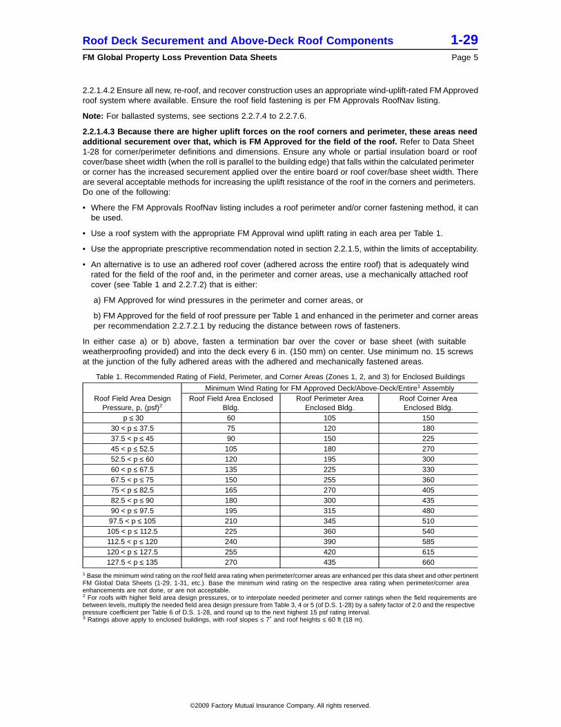
2.2.1.4.3 Because there are higher uplift forces on the roof corners and perimeter, these areas needadditional securement over that, which is FM Approved for the field of the roof. Refer to Data Sheet1-28 for corner/perimeter definitions and dimensions. Ensure any whole or partial insulation board or roofcover/base sheet width (when the roll is parallel to the building edge) that falls within the calculated perimeteror corner has the increased securement applied over the entire board or roof cover/base sheet width. Thereare several acceptable methods for increasing the uplift resistance of the roof in the corners and perimeters.Do one of the following:
• Where the FM Approvals RoofNav listing includes a roof perimeter and/or corner fastening method, it canbe used.
• Use a roof system with the appropriate FM Approval wind uplift rating in each area per Table 1.
• Use the appropriate prescriptive recommendation noted in section 2.2.1.5, within the limits of acceptability.
• An alternative is to use an adhered roof cover (adhered across the entire roof) that is adequately windrated for the field of the roof and, in the perimeter and corner areas, use a mechanically attached roofcover (see Table 1 and 2.2.7.2) that is either:
a) FM Approved for wind pressures in the perimeter and corner areas, or
b) FM Approved for the field of roof pressure per Table 1 and enhanced in the perimeter and corner areasper recommendation 2.2.7.2.1 by reducing the distance between rows of fasteners.
In either case a) or b) above, fasten a termination bar over the cover or base sheet (with suitableweatherproofing provided) and into the deck every 6 in. (150 mm) on center. Use minimum no. 15 screwsat the junction of the fully adhered areas with the adhered and mechanically fastened areas.
Table 1. Recommended Rating of Field, Perimeter, and Corner Areas (Zones 1, 2, and 3) for Enclosed Buildings
Roof Field Area DesignPressure, p, (psf)2
Minimum Wind Rating for FM Approved Deck/Above-Deck/Entire1 AssemblyRoof Field Area Enclosed
Bldg.Roof Perimeter Area
Enclosed Bldg.Roof Corner Area
Enclosed Bldg.p ≤ 30 60 105 150
30 < p ≤ 37.5 75 120 18037.5 < p ≤ 45 90 150 22545 < p ≤ 52.5 105 180 27052.5 < p ≤ 60 120 195 30060 < p ≤ 67.5 135 225 33067.5 < p ≤ 75 150 255 36075 < p ≤ 82.5 165 270 40582.5 < p ≤ 90 180 300 43590 < p ≤ 97.5 195 315 48097.5 < p ≤ 105 210 345 510105 < p ≤ 112.5 225 360 540112.5 < p ≤ 120 240 390 585120 < p ≤ 127.5 255 420 615127.5 < p ≤ 135 270 435 660
1 Base the minimum wind rating on the roof field area rating when perimeter/corner areas are enhanced per this data sheet and other pertinentFM Global Data Sheets (1-29, 1-31, etc.). Base the minimum wind rating on the respective area rating when perimeter/corner areaenhancements are not done, or are not acceptable.2 For roofs with higher field area design pressures, or to interpolate needed perimeter and corner ratings when the field requirements arebetween levels, multiply the needed field area design pressure from Table 3, 4 or 5 (of D.S. 1-28) by a safety factor of 2.0 and the respectivepressure coefficient per Table 6 of D.S. 1-28, and round up to the next highest 15 psf rating interval.3 Ratings above apply to enclosed buildings, with roof slopes ≤ 7˚ and roof heights ≤ 60 ft (18 m).
Roof Deck Securement and Above-Deck Roof Components 1-29FM Global Property Loss Prevention Data Sheets Page 5
©2009 Factory Mutual Insurance Company. All rights reserved.

2.2.1.5 Prescriptive Enhancement Options: Perimeter and Corner
2.2.1.5.1
a) For all deck types, where roof covers are adhered to some combination of mechanically fastenedinsulation, cover board, or thermal barriers, prescriptive enhancements may be used for securement ofthe perimeter and corner areas, as long as one of the conditions below applies:
1. The building is in a non-hurricane prone region where the design wind speed does not exceed 90mph and the roof height does not exceed 75 ft (23 m). Note the roof height is limited to 30 ft (9.1 m) ifthe building is located in surface roughness exposure D (see DS 1-28) and the building is partiallyenclosed.Or,
2. The recommended field of roof rating needed per DS 1-28 does not exceed Class 1-75 (3.6 kPa).Or,
3. The building is in a non-hurricane-prone region (see Appendix A) and the recommended field ofroof rating per DS 1-28 does not exceed Class 1-90 (4.3 kPa).
For any of the three conditions above, increase the number of fasteners per board over the FMApproved field-of-roof spacing by the following:
• 50% minimum in the roof perimeter, but at least one fastener per 2 ft2 (1 per 0.19 m2). It is notnecessary to install fasteners closer than one per 1 ft2 (1 per 0.09 m2).
• One fastener per 1 ft2 (1 per 0.09 m2) in corner areas.
• Round up to the next whole number of fasteners, if necessary
b) For all locations (including hurricane-prone regions), where a Class 1-90 wind rated system is neededfor the field-of-roof, use the following generic assemblies in the perimeter and corner areas to provideacceptable wind resistance in those areas:
Option 1
Minimum 11⁄2 in. (38 mm) thick, FM Approved, Class 1 insulation laid loose directly on the deck.
Minimum 1⁄2 in. (12. 7 mm) thick, FM Approved, water resistant, primed (factory or field primed) gypsumcover board over the insulation. Primer can be omitted if roof cover / coverboard combination meets aClass 1-225 or greater without a primer.
Through-fasten both layers to the steel deck with FM Approved minimum No. 14 (1⁄4 in., 6.4 mm) screwsand flat-bottom metal stress plates. Use 24 fasteners per 4 by 8 ft (1.2 by 2.4 m) board in the perimeter,and 32 fasteners per 4 by 8 ft (1.2 by 2.4 m) board in the corners.
Roof cover – a fully mopped, minimum 3-ply BUR; or a minimum 2-ply mod bit system with all plies fullymopped and/or torch applied per FM Approval requirements.
Option 2
Minimum 2 in. (50 mm) thick, FM Approved, Class 1 insulation laid loose directly on the deck. Note: alesser insulation thickness may be used if included in any Class 1 fire-rated assembly with the othercomponents above it, but not less than 1-1⁄2 in. (38 mm) thick.
Minimum 7⁄16 in. (11.1 mm) thick, oriented strand board (OSB) cover board over the insulation. Ensurethe OSB is APA (American Plywood Association) rated for Exposure 1, with exterior type adhesive.
Through-fasten both layers to the steel deck with FM Approved minimum No. 14 (1⁄4 in., 6.4 mm) screwsand flat-bottom metal stress plates. Note: if screws have oversized heads and are specifically approvedfor OSB or OSB composite boards, stress plates are not required. Use 24 fasteners per 4 by 8 ft (1.2by 2.4 m) board in the perimeter, and 32 fasteners per 4 by 8 ft (1.2 by 2.4 m) board in the corners.
Roof cover – a minimum 3-ply BUR or minimum 2-ply mod bit system with all plies fully mopped, perFM Approval requirements.
1-29 Roof Deck Securement and Above-Deck Roof ComponentsPage 6 FM Global Property Loss Prevention Data Sheets
©2009 Factory Mutual Insurance Company. All rights reserved.

c) For areas where the criteria in the recommendations above are exceeded, ensure the roof system usedin the perimeter and corner areas is FM Approved for the specific wind rating recommended in theperimeter and corner areas (see Table 1). Alternatively, install either a mechanically attached single-plymembrane, or a multi-ply roof cover with a mechanically attached base sheet in accordance with 2.2.7.2.
Note: Insulation and thermal barriers under mechanically fastened roof covers in assemblies that DO NOTincorporate air or vapor retarders do not have to increase the insulation fastening over the field of roofspacing.
2.2.1.5.2 For components adhered with urethane-based adhesives, asphalt, or other adhesives in ribbons,spots, etc., reduce the spacing between ribbons or spots over the FM Approved field-of-roof spacing as notedbelow (round down to a dimension that is practical with respect to board sizes, etc.):
• In the roof perimeter, not more than 60% of the field-of-roof spacing between rows or area
• In the roof corners, not more than 40% of the field-of-roof spacing between rows or area
Note: If the FM Approval rating for wind meets the criteria in Table 1 for the perimeter or corner area, nofurther reduction is needed in those areas.
Example: A particular roof cover as FM Approved is adhered with a urethane-based adhesive in ribbons at1 ft (0.3 m) on center in the field of the roof. The perimeter would need a ribbon spacing of 6 in. (150 mm)and the corners would need a ribbon spacing equal to 4 in. (100 mm) on-center. Note: these spacings wererounded down slightly for practicality.
2.2.1.5.3 For mechanically attached single-ply membranes, and multi-ply covers with a mechanically attachedbase sheet, refer to section 2.2.7.2.
2.2.1.5.4 For mechanically attached base sheets, refer to section 2.2.9 or 2.2.11 if the base sheet is fasteneddirectly to a wood deck.
2.2.1.5.5 For ballasted systems, refer to section 2.2.7.4.
2.2.1.5.6 For steel decks, increase the number of deck fasteners at each joist or purlin support over thefield-of-roof FM Approvals RoofNav listing in accordance with 2.2.13. Shorter spans that yield an equivalentincrease in deck securement strength are acceptable, but may not always be practical.
2.2.1.6 External Fire Resistance—Design Recommendations
2.2.1.6.1 Assemblies having an American Society for Testing and Materials (ASTM) E108 Class A rating arepreferred in all cases, and are specifically recommended as follows:
a) Where the exterior fire exposure to the roof is severe.
b) On the entire roof of buildings subdivided by MFL fire walls. Refer to Data Sheet 1-22, Criteria forMaximum Foreseeable Loss Fire Walls and Space Separation, for details on additional surface protectionneeded adjacent to the wall and roof protection for buildings where MFL space separation is a factor.
c) For occupancies particularly susceptible to smoke or water damage.
2.2.1.6.2 ASTM E108 Class C rated assemblies are not recommended on any roofs >10,000 ft2 (930 m2).
2.2.1.6.3 The use of pea gravel surfacing installed in accordance with 2.2.1.7.1 is considered to provide aClass A exterior fire exposure rating. While not normally recommended in hurricane-prone regions due toits potential to become windborne debris, it may be accepted in hurricane-prone regions (such as whererequired adjacent to fire subdivisions), provided that all gravel remaining at the end of the installation is fullyembedded into the bitumen and there is no loose gravel nested on top. The following method will providesuch compliance:
a) Aggregate is applied into a flood coat of hot bitumen, and allowed to cool and harden.
b) Loose aggregate is pushed away, a second flood coat is applied, and the loose gravel is applied backinto the second flood coat and allowed to cool and harden.
c) Any remaining loose gravel is removed from the site .
Roof Deck Securement and Above-Deck Roof Components 1-29FM Global Property Loss Prevention Data Sheets Page 7
©2009 Factory Mutual Insurance Company. All rights reserved.

2.2.1.7 Hail Resistance: Design Recommendations
2.2.1.7.1 Use only FM Approved roof cover systems meeting the severe hail (SH) criteria in the hail stormhazard area shown in Figure 1. Unless specifically FM Approved with other surface treatments, built-up roofs(BUR) may be used in SH and MH areas, provided:
• they are covered with gravel at a minimum of 400 lb per square (19.5 kg/m2) or slag at a minimum of 300 lbper square (14.6 kg/m2). (See Appendix A, Glossary, for definition of square.)
• aggregate is in accordance with ASTM D1863.
• aggregate is applied into a minimum 60 lb per square (2.9 kg/m2) bitumen flood coat.
Note: Do not use pea gravel in regions prone to hurricanes, typhoons ancd tropical cyclones except whereinstalled in accordance with section 2.2.1.6.3. Otherwise, use FM Approved coatings in lieu of pea gravel.
2.2.1.7.2 For U.S. locations outside the hail area, MH or SH rated systems can be used.
2.2.1.7.3 At locations outside the U.S., MH rated systems can be used unless local weather records indicatethe need for greater hail resistance. Generally, consider SH rated systems for locations with an average ofthree or more hail storms per year.
2.2.1.8 Internal Fire Resistance—Noncombustible, Class 1, and Class 2 Assemblies—Design andInstallation Recommendations
2.2.1.8.1 As all FM Approved roof systems are Class 1 or noncombustible, Class 1 or noncombustibleassemblies are recommended in all cases. When there is an existing Class 2 deck and an unsprinkleredconcealed space below the deck, refer to Data Sheet 1-12, Ceilings and Concealed Spaces, for fire protectionguidance.
2.2.1.8.2 Class 2 steel roof decks can be converted to Class 1 by applying an FM Approved undercoating.If this is done, adhere to the following recommendations:
• Ensure the underside of the deck is clean before coatings are applied.
• Ensure FM Approved coatings are applied by applicators licensed by the coating manufacturer.
• Do not use cellulose-based undercoatings in high humidity occupancies as the fire retardant chemicalsare water soluble and can leach out of the coating.
• Do not use steel deck undercoatings where combustible residue can accumulate on the surface.
2.2.2 Vapor Retarders (Barriers)—Design and Installation Recommendations
These recommendations outline vapor retarder applications that maintain Class 1 and appropriate wind upliftratings.
2.2.2.1 If a vapor retarder is used, ensure it is FM Approved and applied in a single layer placed directlyon the deck. Side and end laps are sealed using FM Approved adhesive. The remaining roof componentsare then installed with fasteners driven through the retarder into the deck (Fig. 2). The components above theFM Approved vapor retarder can be any combination of materials FM Approved for use together onthe particular deck. Some systems are FM Approved with the retarder installed above a base layer ofinsulation; see section 2.2.2.3 below.
2.2.2.2 On panel-type decks (decks with seams such as steel, wood, pre-cast planks, etc.), if a vapor retarderis installed below the insulation or coverboard of a mechanically secured single-ply membrane (perrecommendation 2.2.2.1 above), secure the insulation or coverboard with FM Approved insulation fastenersand plates using one of the following options:
1. A rate of 1 per 2 ft2 (1 per 0.19 m2) throughout the entire roof area, OR
2. A rate throughout the entire roof area that will obtain a minimum 1-90 uplift FM Approval with anadhered single-ply roofing membrane as specified in a RoofNav listing. The insulation/coverboard typeused below the mechanically secured membrane must match that specified by the RoofNav listingfor the adhered membrane, and the thickness of the insulation/coverboard must be equal to or greaterthan that specified by the RoofNav listing.
A vapor retarder is located on the “warm side” of the roof or sandwiched between insulation layers. The vaporretarder is sealed to the exterior walls of the building, but not necessarily to the underside of the roof cover.
1-29 Roof Deck Securement and Above-Deck Roof ComponentsPage 8 FM Global Property Loss Prevention Data Sheets
©2009 Factory Mutual Insurance Company. All rights reserved.

©2009 Factory M
utual Insurance Com
pany. All rights reserved
Fig. 1. Hailstorm hazard map for United States (areas subject to severe hailstorms and need an SH hail rated roof)
FM G
lobal Property Loss Prevention Data Sheets
Page 9
Roof D
eck Securement and A
bove-Deck R
oof Com
ponents1-29
Chattanooga
Concord
Nashville
Bangor
Memphis
Ludington
Louisville
Kapuskasing
Sault St Marie
ProvidenceBuffalo
Montpelier
Knoxville
HuntsvilleOttawa
Toronto
Montreal
BostonMarquette
Hartford
Green Bay
Kahoka
Chicago
Indianapolis
Albany
Milwaukee
Moline
Springfield
Saint Louis
Fort Wayne
Detroit
London
SaranacLake
NEWFOUNDLAND
Buchans
St. Johns
Montgomery
Gander
Mobile
Columbia
Charleston
Savannah
Atlanta
Jacksonville
Tampa
Ashville
RaleighWytheville
Norfolk
Richmond
Charleston
CincinnatiColumbus
Cleveland
PittsburghHarrisburg
Philadelphia
Little Rock
Sidney
Jackson
Charlottetown
Miami
ChathamAmherst
Quebec
Shreveport
Baltimore
New Orleans
Washington DC
Trenton
Birmingham
Halifax
Port Arthur
Churchill
Saskatoon
The Pas
WinnipegSioux Lookout
Souix City
Des Moines
Minneapolis
Regina
Pierre
DuluthFargoBismarck
Aberdeen
KansasCity
SiouxFalls
North Platte
In ternationalFalls
PrinceAlbert
MedicineHat
Calgary
Edmonton
Cranbrook
VancouverPenticton
NelsonVictoria
Clayoquot
Kamloops
PrinceGeorge
PrinceRupert
Havre
San Diego
Fort Smith
Springfield
MEXICO
Joplin
CANADA
Houston
Fresno
Baker City
Denver
Williston
San Antonio
Pueblo
Dallas
Las Vegas
Boise
Oklahoma City
Portland
Cheyenne
Tucson
Los Angeles
Phoenix
Wichita
Santa Fe
Spokane
El Paso
Topeka
Amarillo
Seattle
Sacramento
Eureka
San Francisco
Red Bluff
Pocatello
RenoSalt Lake City
Sheridan
Lander
Helena
Billings
PacificOcean
AtlanticOcean
Gulf of Mexico
Gulf of California
H ecateStrait
JamesBay
Gulf ofSt. Lawrence
Gulf ofMaine
LakeHuron
LakeMichigan
Lake Superior
Hudson Bay
200 0 200 400 Kilometers600
0 200 400 Miles200
Exposure toDamaging Hailstorms
ModerateSevereNo Data
25°
55°
50°
45°
40°
35°
30°
75°80°85°90°95°100°105°110°115°120°

An air barrier is used with a mechanically fastened roof cover and is located directly above the roof deck.The air barrier is sealed to the underside of the roof cover, but not necessarily to the exterior walls of thebuilding. In theory, an air barrier improves wind uplift resistance of the roof assembly by preventing air flow intothe space below the roof cover and transferring a portion of the uplift load to the insulation. It should be notedthat even for properly installed air barrier systems, roof penetrations made after the installation of an airbarrier system can hamper the wind performance of an air barrier system if the air barrier is not sealed tothe underside of the roof cover after the penetration cut is made. Consequently, there are special FMApproval restrictions on air barrier systems.
2.2.2.3 Fastener penetration of the vapor retarder can be avoided by using an FM Approved fastened/adheredassembly. Ensure all materials are FM Approved for use in combination. Ensure substitution ofmaterials is not made.
2.2.2.4 Do not mop asphalt/felt vapor retarders directly on to any deck (this would result in a Class 2 roof)except structural concrete.
2.2.3 Roof Insulation
2.2.3.1 Design Recommendations
2.2.3.1.1 Ensure insulation boards are FM Approved for the specific application, including specific roof cover,fasten/mop construction, multiple layers, etc. Using assemblies that are not FM Approved can result in aClass 2 and/or inferior roof construction. However, combinations that may not be FM Approved but can beaccepted are noted in sections 2.2.3.1.2, 2.2.3.1.3, and 2.2.3.1.4.
2.2.3.1.2 It is acceptable to use multiple layers of FM Approved insulation, mechanically secured throughall layers, provided all of the following are true:
• All layers are the same insulation.
• The total insulation thickness is not greater than the maximum FM Approved thickness of the insulation.
• The mechanical fastening and wind uplift rating are per the FM Approval of the top layer.
• The roof cover/insulation/fastener combination is FM Approved.
2.2.3.1.3 Insulation board sizes listed in the Approval Guide are the minimum FM Approved sizes. Boardsup to 4 × 8 ft (1.2 × 2.4 m) can be used except as noted in section 2.2.3.1.4 (with a proportional increasein fasteners, adhesive ribbons, etc. rounding up to the next whole number). Do not use boards smaller thanFM Approved except per section 2.2.3.2.2.
Fig. 2. Insulation and vapor barrier mechanically fastened to steel deck.
1-29 Roof Deck Securement and Above-Deck Roof ComponentsPage 10 FM Global Property Loss Prevention Data Sheets
©2009 Factory Mutual Insurance Company. All rights reserved.

2.2.3.1.4 The maximum recommended insulation board size, if the board is adhered with asphalt or adhesive,is 4 × 4 ft (1.2 × 1.2 m). Exception: Flexible boards such as maximum 1⁄2 in. (13 mm) thick wood fiber or5⁄8 in. (16 mm) gypsum board may be adhered at board sizes up to 4 × 8 ft (1.2 × 2.4 m).
2.2.3.2 Installation Recommendations
2.2.3.2.1 Stagger insulation board joints in one direction (the shorter sides staggered if boards are not square).Support the two opposite sides of each board on steel deck flanges, as close as practical to the center ofthe flange with a minimum bearing width of 1 in. (25 mm). Trim board edges if they veer off the flange center.
2.2.3.2.2 When insulation boards are cut, as is common at the roof edge to produce staggered joints, secureeach piece with the appropriate number of fasteners, adhesive ribbons, etc. for the full board times thepercentage area of the piece, rounding up to the next whole number.
2.2.3.2.3 Install only as much insulation or gypsum-based board as can be covered each working day. Sealloose roof cover edges at the end of each day to minimize moisture damage. Do not allow water to run insteel deck ribs under completed roof sections.
2.2.3.2.4 Ensure insulation is set on pallets or dunnage and protected from the weather and sunlight priorto installation. Do not allow plastic to cover the insulation as it can allow condensation. A breathable material,such as canvas, is recommended.
2.2.3.2.5 Ensure FM Approved job-mixed material (like LWIC) is installed by applicators licensed by themanufacturer. Steel deck that meets the insulation manufacturer’s span and gauge requirements is necessaryto support the application equipment. Such systems are a possible option when penetration of the deck withmechanical fasteners is not desired.
2.2.3.2.6 Provide preliminary securement of insulation boards when mechanically fastened roof covers areused (single-plies or multi-plies with fastened base sheets). Install a minimum of two fasteners per 4 x 4 ft (1.2x 1.2 m) board or four fasteners per 4 x 8 ft (1.2 x 2.4 m) board, unless the manufacturer requires a greaternumber. Additional insulation fastening is not required in the perimeter and corner areas. Where a vaporretarder is used below a mechanically fastened roof cover, see section 2.2.2.2.
2.2.4 Insulation and Roof Cover Fasteners
2.2.4.1 Design Recommendations
2.2.4.1.1 FM Approved insulation fasteners are the only FM Approved and recommended method of securinginsulation boards or other boardstock materials to steel deck. Some fasteners are FM Approved for otherdeck materials.
2.2.4.1.2 When fastener pull-out tests are performed on new construction to evaluate the deck integrityor evaluate decks that are not FM Approved, run a minimum of five tests and use the average value. Seesection 2.2.5.2.6 for the number of tests for recover/reroof construction.
2.2.4.1.3 When pull-out tests are done, base the fastener density on the more conservative of either theFM Approved spacing for the fastener plate/insulation/roof cover combination, or the spacing needed basedon the average pull-out performance.
Example: An existing deck is oriented strand board (OSB). The fastener/insulation/roof cover combinationis FM Approved for 4 fasteners per 4 × 4 ft (1.2 × 1.2 m) board for Class 1-90 on steel deck. The calculatedload per fastener would be 360 lb (1600 N) ([4 ft2/fastener][90 psf] = 360 lb/fastener). If the proposed fastenerachieved a pull-out resistance of 360 lb (1600 N) or more in the deck, the FM Approved spacing would beused. If the fastener achieved a resistance of less than 360 lb (1600 N), for example 300 lb (1335 N), calculatethe spacing as follows: (16 ft2)(90 psf)/(300 lb) = 4.8 fasteners per board; use five fasteners per board inthe roof field. Additional fasteners would be needed in the corners and perimeter per section 2.2.1.4.3. Thepercentage increase would be applied to five fasteners per board, not four.
2.2.4.2 Installation Recommendations
2.2.4.2.1 Install fasteners only through dry substrates. Wet constructions can cause deterioration of fasteners,including FM Approved corrosion-resistant fasteners. Exception: Fasteners FM Approved for use in newlightweight insulating concrete decks are designed to be tolerant of the moisture present at the time ofinstallation.
Roof Deck Securement and Above-Deck Roof Components 1-29FM Global Property Loss Prevention Data Sheets Page 11
©2009 Factory Mutual Insurance Company. All rights reserved.

2.2.4.2.2 Use only FM Approved fastener/plate combinations. Do not install stress distribution plates fromone manufacturer with another manufacturer’s fastener unless the combination is FM Approved.
2.2.4.2.3 Fasteners must be driven perpendicular to the deck to be effective. Particular caution is neededwith tapered insulations.
2.2.4.2.4 Use the manufacturer’s proprietary installation tool. A less desirable option is a properly adjustedscrew gun, having a depth-sensing clutch, to avoid over-driving or under-driving screw-type fasteners.
2.2.4.2.5 Recommended Fastener Embedment:
Sructural concrete: 1 to 11⁄2 in. (25-38 mm),
Wood decks: Minimum 1 in. (25 mm). Note: For 3⁄4 in. (19 mm) thick plywood deck, approximately 1⁄4 in.(6 mm) of the screw will protrude through the deck underside.
Steel deck: For screw-type fasteners in new construction, use the shortest screw that is at least 3⁄4 in.(19 mm) longer than the assembly being secured. Ensure fasteners engage the deck top flange. For recoversteel deck construction, the fastener must be long enough to be driven through the existing roof system andinto the deck at least 3⁄4 in. (19 mm). While top flange engagement is recommended in all cases, for recoverconstruction, it is acceptable for insulation fasteners to engage the bottom flange of the deck. Ensurefasteners securing mechanically attached roof covers engage the top flange of the deck in all constructions.
For other deck types: Follow the FM Approval requirements and manufacturers’ specifications.
2.2.4.2.6 Ensure insulation fastener placement is per Figures 3, 4, 5, and 6. If a particular insulation has adifferent required FM Approved fastener pattern, use that. Each fastener must engage the intended deckflange. This results in a spacing tolerance of approximately ± 1.5 in. (± 38 mm) for wide-rib deck if the edgeof the board was at the centerline of the deck top flange. For smooth decks, such as plywood or concrete andsteel deck in the direction of deck ribs, a maximum tolerance of ± 1.5 in. (± 38 mm) is acceptable.
1-29 Roof Deck Securement and Above-Deck Roof ComponentsPage 12 FM Global Property Loss Prevention Data Sheets
©2009 Factory Mutual Insurance Company. All rights reserved.

Fig. 3. Fastener placement 2 × 4 ft (0.6 × 1.2 m) boards.
Roof Deck Securement and Above-Deck Roof Components 1-29FM Global Property Loss Prevention Data Sheets Page 13
©2009 Factory Mutual Insurance Company. All rights reserved.

Fig. 4. Fastener placement 3 × 4 ft (0.9 × 1.2 m) boards.
1-29 Roof Deck Securement and Above-Deck Roof ComponentsPage 14 FM Global Property Loss Prevention Data Sheets
©2009 Factory Mutual Insurance Company. All rights reserved.

Fig. 5. Fastener placement 4 × 4 ft (1.2 × 1.2 m) boards.
Roof Deck Securement and Above-Deck Roof Components 1-29FM Global Property Loss Prevention Data Sheets Page 15
©2009 Factory Mutual Insurance Company. All rights reserved.

For fastening densities not shown, the following guidelines apply:
• Ensure edge fasteners are 6 in. (152 mm) from the board edges, with tolerance as above.
• Ensure fasteners are evenly distributed over the board area.
• Ensure all fasteners engage the top flange of steel deck. (See note for recover construction, section2.2.4.2.5 above.)
2.2.5 Recover and Reroof Construction—Design and Installation Recommendations
This section covers planned recover and reroof operations. For repairs after wind damage has occurred,refer to Data Sheet 1-30, Repair of Wind Damaged Roof Systems.
2.2.5.1 Reroof Construction—Removal and Replacement of Above-Deck Components
2.2.5.1.1 Reroof construction is generally preferred to recover construction due to the potential for moisturedamage with recover construction from existing wet insulation inadvertently left in place.
Fig. 6. Fastener placement 4 × 8 ft (1.2 × 2.4 m) boards.
1-29 Roof Deck Securement and Above-Deck Roof ComponentsPage 16 FM Global Property Loss Prevention Data Sheets
©2009 Factory Mutual Insurance Company. All rights reserved.

2.2.5.1.2 When reroofing, inspect the existing deck securement and, if necessary, fasten the deck per DataSheet 1-28, Wind Design, prior to installation of the above-deck components.
2.2.5.1.3 When reroofing over a steel deck where the original assembly had been adhered with asphalt, doone of the following:
• Use an insulation specifically FM Approved for reroofing; that allows up to 15 lb per square (72 kg/100 m2)of asphalt to remain on the deck.
• Remove all asphalt from the deck and install a system FM Approved for new construction.
2.2.5.2 Recover Construction—Existing Components Remain
All recover recommendations and FM Approvals are based on the assumption that there is only one existingroof system. If more than one roof system is in place (building has already been recovered), use reroofconstruction.
2.2.5.2.1 If recover construction is considered, perform the following actions:
• Remove all wet materials prior to application of the new roof system, with wet insulation being replacedwith dry material.
• Cut out blisters.
Roof cover blistering or rusting deck may be an indication that the existing insulation is wet. When this isobserved, take one of the following steps:
• Reroof, as opposed to recover. See section 2.2.5.1.
• Conduct an infrared or nuclear examination to detect any high-moisture content.
If moisture is detected with one of these nondestructive methods, confirm the results by cutting out 1 × 1 ft(0.3 × 0.3 m) samples or roof cores as needed to determine the extent of wet insulation.
2.2.5.2.2 Recover—mechanically attached recover systems. If the existing construction is dry, anFM Approved recover system can be applied over it. Ensure the entire assembly (insulation, fasteners,and roof cover) is FM Approved in combination for recover construction on the particular deck.
2.2.5.2.3 Ensure the thickness of the recover system is within the FM Approval limits. Most systems are limitedto a maximum 1 in. (25 mm) thick roof insulation. A greater thickness may affect the Class 1 fire rating ofthe completed system. Installation of an FM Approved Class 1 recover assembly over an existing Class 2 roofsystem will not upgrade the assembly to Class 1. However, it would be possible to upgrade the externalfire resistance rating (E108) with the addition of an FM Approved roof cover system.
2.2.5.2.4 When brooming gravel from the roof, do not pile it in one area. This can overload structural memberscausing collapse.
2.2.5.2.5 Do not use recover constructions using additional plies adhered directly to an existing BUR unlessthe entire assembly is FM Approved. This would essentially result in a 6- or 7-ply BUR over the insulation(3- or 4-ply existing BUR plus 3 plies added), most likely creating a Class 2 roof assembly.
2.2.5.2.6 When reroofing or recovering over gypsum, cementitious wood fiber, or lightweight insulatingconcrete decks, verify fastener pull-out performance with field tests. Perform 5 pull-out tests per 50,000 ft2
(4650 m2) using FM Approved fastening or a minimum of 5 tests. Run additional tests if inconsistent resultsare obtained. On larger roofs, the number of tests above the minimum can be reduced if consistent resultsare obtained. Fastener spacing is calculated per section 2.2.4.1.3. It is not necessary to run pull-out testsof fasteners FM Approved for installation in steel deck, structural concrete, nominal 3⁄4 in. (19 mm) plywood,or nominal 2 in. (51 mm) lumber decks, unless the condition of the deck is in question.
2.2.6 Structural Concrete, FM Approved Fiber Reinforced Cement and Lightweight InsulatingConcrete (LWIC) Decks: Design and Installation Recommendations
NOTE: also see section 2.2.14 for LWIC and 2.2.17 for Structural Concrete Decks
2.2.6.1 When an FM Approved asphaltic adhesive or asphalt is used to secure components to these decks,prime the deck with an FM Approved primer at the FM Approved rate, or with an ASTM D-41 asphalt cut-backprimer at 0.75 to 1.25 gal per square (3.0 to 5.1 L/10 m2).
Roof Deck Securement and Above-Deck Roof Components 1-29FM Global Property Loss Prevention Data Sheets Page 17
©2009 Factory Mutual Insurance Company. All rights reserved.

2.2.7 Single-Ply Membrane Covers and Multi-Ply covers with Mechanically Attached Base Sheets
Loss experience has shown that even properly secured single-ply roof covers can be damaged by windbornedebris such as metal panels and broken glass. In areas prone to hurricanes, typhoons and tropical cyclones(see DS 1-28), use more durable roof covers. This would include multi-ply roof covers or single-plymembranes that are considerably thicker than the FM Approved minimum. Many single-ply membranes aremanufactured in thicknesses up to 0.080 to 0.090 in. vs. the minimum FM Approved thickness of 0.045 to0.060 in.
2.2.7.1 General
2.2.7.1.1 Single-ply membranes can deteriorate when exposed to certain materials commonly dischargedonto the roof. Also separate these membranes from incompatible substrate materials. In particular, ensuresingle-ply membranes do not come into contact with asphalt or coal tar-based materials. Ensure EPDMmembranes are not exposed to gasoline, oil, solvents, or animal fats. Ensure PVC membranes are not indirect contact with EPS. Follow the manufacturer’s recommendations for protection or separation.
2.2.7.1.2 Some FM Approved single-ply membranes are formulated with fire retardants on the top side only.Install these systems with that surface up. Membranes with this requirement are labeled on the underside‘‘THIS SIDE DOWN/IN.’’
2.2.7.2 Mechanically Attached Single-ply Membranes and Multi-Ply Covers with MechanicallyAttached Base Sheets: Design Recommendations
2.2.7.2.1 In the roof corners and perimeter, ensure the distance between rows of roof cover fasteners orbatten bars are the following maximum percentages of the FM Approved spacing. Use the reduced spacingin all FM Approval classifications:
Roof Perimeter: Distance between rows is ≤ 60% of the FM Approved roof field spacing, or one row ofintermediate fasteners is provided in between.
Roof Corners: Distance between rows is ≤ 40% of the FM Approved roof field spacing or two rows ofintermediate fasteners are provided in between. An alternative for Class 1-90 and below (on steel deck) isto install perimeter fastener rows (60% of roof field as above) in both directions in the corners (any wind classacceptable for other types of decks). Refer to Figure 7. When the cover overlaps in the corner areas, installthese fasteners from above the uppermost cover layer.
• For single-plies fastened along the side laps:
Increased fastening density for single-ply membranes is often obtained by using narrower sheets. Forsingle-ply membranes or base sheets, intermediate rows of fasteners may be installed through the sheetwith a cover strip or additional plies applied over the fasteners, in accordance with the manufacturer’sinstructions. Use one intermediate row in the perimeter and two intermediate rows in the corners. Fasteningincrease is not always obtained by increasing the number of fasteners along each row, unless substantiatedby FM Approval test data or otherwise done to provide a more practical spacing and distribution of windloads. In some cases, such as over wood decks (see 2.2.11) or LWIC, or with mod bit base sheets in highwind areas, enhanced securement for base sheets is provided by reducing the fastener spacing within andbetween rows in order to provide a uniform distribution (see section 3.1.2.1 for examples). When steel deckis used, the fastener spacing across the deck ribs must be in even multiples of the deck rib spacing (6 in. or150 mm for 11⁄2 in. or 38 mm deep deck) to ensure the fastener engages the top deck flange. See Example 1.
• For point-attached membranes:
Increased fastening density is obtained by decreasing the spacing between fastener points in one or bothdirections. Ensure total tributary area to each fastener is no more than 60% and 40% in the perimeter andcorners, respectively, of the FM Approved roof field spacing. See Example 2.
Example 1: A batten-attached system with FM Approved fastener spacing for Class 1-60 of rows 6 ft (1.8 m)on center and screws 6 in. (152 mm) on center would use 3.6 ft (1.1 m) maximum on center row spacing,with 6 in. (152 mm) on-center screw spacing in the perimeter and 2.4 ft (0.7 m) maximum on-center rowspacing with 6 in. (152 mm) on-center screw spacing in the corners. In this case, rows of roof cover fastenersshould extend across the deck ribs in all areas to properly distribute the load to points of deck securement.Since the needed wind uplift rating is limited, an option would be to use row spacing of 3 ft (0.9 m) maximumin both directions in the corners per Figure 7, and 2.2.7.3.2.
1-29 Roof Deck Securement and Above-Deck Roof ComponentsPage 18 FM Global Property Loss Prevention Data Sheets
©2009 Factory Mutual Insurance Company. All rights reserved.

Fig. 7. Alternate corner increase for mechanically attached single-ply membranes.Note: Fastener spacing along all rows is the same as field spacing.
Notes: 1. Fastener spacing along all rows is the same as field spacing.2. See section 2.2.7.3.2. for restrictions on fastener rows parallel to steel deck ribs.3. If two layers of membrane are installed in the corner areas, all fasteners must secure the top
layer.
Roof Deck Securement and Above-Deck Roof Components 1-29FM Global Property Loss Prevention Data Sheets Page 19
©2009 Factory Mutual Insurance Company. All rights reserved.

Example 2: A point-attached system with FM Approved fastener spacing for Class 1-90 of 24 × 24 in.(610 × 610 mm) could use a spacing of 14 × 24 in. (356 × 610 mm) in the perimeter. A 12 × 24 in.(305 × 610 mm) spacing may be needed for steel deck applications depending on deck rib direction.
A spacing of 10 × 24 in. (256 × 610 mm) in the corners could be used. A 12 × 18 in. (305 × 457 mm) maybe needed for steel deck applications depending on deck rib direction.
2.2.7.3 Mechanically Attached Single-Ply Membranes and Multi-Ply Covers with MechanicallyAttached Base Plies—Installation Recommendations
2.2.7.3.1 Ensure all roof cover fasteners engage the top flanges of steel deck.
2.2.7.3.2 Install batten bars and fastener rows perpendicular to steel deck ribs. Exception: for Class 1-75and below, fastener rows and batten bars can be installed parallel to the building edge within the definedbuilding perimeter width if:
a) the distance between fastener rows in this area is ≤ 3 ft (0.9 m), and
b) two FM Approved deck fasteners or minimum 5⁄8 in. (16 mm) diameter welds are installed through eachlower deck flange (every 6 in., 150 mm on center)
2.2.7.3.3 Where acceptable to the roof cover manufacturer, in lieu of seaming numerous partial single-plymembrane sheets in the rake areas, an FM Approved batten bar may extend across the perimeter width,midway between rows of fasteners and be fastened to the deck. Adhere a membrane strip of a minimum widthas recommended by the manufacturer over the batten bar and the edges caulked to maintain water-tightness,if needed. Similar enhancements may be provided in the corner areas using two intermediate batten bars.
2.2.7.3.4 Provide deck securement as follows when the FM Approved (field-of-roof) spacing between rows ofroof cover fasteners exceeds 6 ft (1.8 m):
a) Use only FM Approved deck fasteners to secure the deck. Ensure the spacing within rows of deckfasteners in the field-of-roof does not exceed the spacing within rows of roof cover fasteners.
b) Double the deck fastening in the roof perimeter. For example, if roof cover fasteners are 12 in. (300mm) on center in the field, provide deck fasteners 12 in. on center in the field (per a.) and provide deckfasteners at 6 in. (150 mm) centers in the perimeter. If cover fasteners are 6 in. (150 mm) on center inthe field, provide deck fasteners at 6 in. centers in the field (per a.) and provide two deck fasteners at 6in. (150 mm) centers in the perimeter.
c) In corner areas, use the same number of deck fasteners as for the perimeter, but with ¾ in. diameterwashers. Ensure washers are carbon steel with a 0.328 in. (8.4 mm) center hole and are minimum 0.065in. (1.6 mm) thick.
2.2.7.4 Ballasted Single-Ply Membrane: Design Recommendations
2.2.7.4.1 Do not use stone-ballasted roofs on buildings taller than 150 ft (46 m) high, or in areas with designwind speeds ≥ 100 mph (45 m/s) (See Data Sheet 1-28, Wind Design) or beyond the acceptable limits ofTables 2 or 3. These limitations do not apply to paver ballasted systems.
2.2.7.4.2 To ensure the quality of the materials, component compatibility, and Class 1 undeside fire exposureratings, ensure individual components in ballasted systems are FM Approved for use in combination.Typically, the combination would be FM Approved for adhered or mechanically attached applications. Use onlyFM Approved membranes in ballasted applications.
2.2.7.4.3 Ensure stone ballast in loose-laid systems is clean, smooth, well-rounded gravel meeting thegradation requirements of Standard Size No. 3 for Coarse Aggregate per ASTM D448 (nominal 1 to 2 in.[25 to 50 mm] diameter).
2.2.7.4.4 Ensure the density of stone ballast is approximately 165 pcf (2650 kg/m3). Do not use lightweightstone such as limestone.
2.2.7.4.5 Apply stone ballast per Table 2 or 3. Install paver blocks per Tables 4 to 7. Ensure square edgepavers are a minimum of 1 ft2 (0.1 m2). Ensure beveled/strapped pavers are a minimum of 0.89 ft2 (0.08 m2)(8 × 16 in., [203 × 404 mm]). All weights are the minimum recommended weights.
1-29 Roof Deck Securement and Above-Deck Roof ComponentsPage 20 FM Global Property Loss Prevention Data Sheets
©2009 Factory Mutual Insurance Company. All rights reserved.

2.2.7.4.6 For ballast application only, the roof perimeter and corners are subject to a minimum dimensionof 8.5 ft (2.6 m) rather than 4 ft (1.2 m) as defined in Data Sheet 1-28, Wind Design. Also, the 10% lesserbuilding plan dimension limit is not applied in determining the corner dimension. The 4 ft (1.2 m) minimumand the 10% limit still apply to roof deck securement.
2.2.7.4.7 The structure must be capable of supporting the dead weight of the roof system and ballast withoutencroaching on live load capacity or creating or aggravating a ponding problem. Have the load capacity ofthe roof verified by a registered civil or structural engineer.
2.2.7.4.8 The roof slope should be ≤ 10°, 2 in./ft (167 mm/m).
2.2.7.4.9 Stone ballast can be used in the roof field with pavers used at the perimeter and corners, providedthe appropriate weights of stone and pavers are used in each area.
2.2.7.4.10 Ensure flashing systems used with pavers secure the pavers at the building edge.
2.2.7.5 Ballasted Single-Ply Membrane—Installation Recommendation
2.2.7.5.1 Extreme care is needed when transporting ballast to the roof. Stop the conveying machine if ballastbegins to pile up. Distribute ballast to the specified weight before restarting the conveying machine.
2.2.7.6 Ballasted Single-Ply Membrane—Maintenance Recommendation
2.2.7.6.1 Inspect ballasted roofs semi-annually and after storms. Redistribute scoured ballast. Gravel scourgreater than 50 ft2 (5 m2) is considered excessive. See Data Sheet 1-30, Repair of Wind Damaged RoofSystems, for action to be taken if this type of damage occurs.
Table 2. Weight Needed of No. 3 Round Stone Ballast, Parapet ≤ 36 in. (914 mm)
Uplift Pressure(psf) DataSheet 1-28
Ballast Weight, (psf)Steel or Pre-Cast Panel Deck Cementitious Wet Fill Deck
Field Peri. Cors. Field Peri. Cors.≤ 20 10 12 15 10 10 10
21 to 25 12 15 15 10 12 1226 to 30 12 15 18 12 12 1531 to 35 Use FM Approved 1-90 System 12 15 1836 to 45 Use FM Approved 1-90 System Use FM Approved 1-90 System
Table 3. Weight Needed of No. 3 Round Stone Ballast, Parapet > 36 in. (914 mm)
Uplift Pressure(psf) DataSheet 1-28
Ballast Weight, psfSteel or Pre-Cast Panel Deck Cementitious Wet Fill Deck
Field Peri. Cors. Field Peri. Cors.≤ 20 10 10 12 10 10 10
21 to 25 12 12 12 10 10 1226 to 30 12 12 15 12 12 1231 to 35 12 15 18 12 12 1536 to 45 Use FM Approved 1-90 System 15 15 18
Table 4. Weight Needed of Paver Blocks—not T&G, Beveled or Strapped to Each Other, Parapet ≤ 36 in. (914 mm)
Uplift Pressure(psf) DataSheet 1-28
Paver Weight, psfSteel or Pre-Cast Panel Deck Cementitious Wet Fill Deck
Field Peri. Cors. Field Peri. Cors.≤ 15 12 12 15 12 12 12
16 to 20 12 15 20 12 12 1521 to 25 12 18 23 12 15 1826 to 30 15 23 30 12 18 2131 to 35 Use FM Approved 1-90 System 15 21 2336 to 45 Use FM Approved 1-90 System Use FM Approved 1-90 System
Roof Deck Securement and Above-Deck Roof Components 1-29FM Global Property Loss Prevention Data Sheets Page 21
©2009 Factory Mutual Insurance Company. All rights reserved.

Table 5. Weight Needed of Paver Blocks—not T&G, Beveled or Strapped to Each Other, Parapet > 36 in. (914 mm).
Uplift Pressure(psf) DataSheet 1-28
Paver Weight, psfSteel or Pre-Cast Panel Deck Cementitious Wet Fill Deck
Field Peri. Cors. Field Peri. Cors.≤ 15 12 12 12 12 12 12
16 to 20 12 12 15 12 12 1221 to 25 12 15 18 12 12 1526 to 30 15 18 21 12 15 1831 to 35 Use FM Approved 1-90 System 15 18 2136 to 45 Use FM Approved 1-90 System Use FM Approved 1-90 System
Table 6. Weight Needed of Paver Blocks—T&G, Beveled or Strapped to Each Other, Parapet ≤ 36 in. (914 mm)
Uplift Pressure(psf) DataSheet 1-28
Paver Weight, psfSteel or Pre-Cast Panel Deck Cementitious Wet Fill Deck
Field Peri. Cors. Field Peri. Cors.≤ 15 12 12 12 12 12 12
16 to 20 12 12 15 12 12 1221 to 25 12 15 15 12 12 1226 to 30 12 15 18 12 12 1531 to 35 15 18 18 12 15 1836 to 40 Use FM Approved 1-90 System 12 18 18
Table 7. Weight Needed of Paver Blocks—T&G Beveled or Strapped to Each Other, Parapet > 36 in. (914 mm)
Uplift Pressure(psf) DataSheet 1-28
Paver Weight (psf)Steel or Pre-Cast Panel Deck Cementitious Wet Fill Deck
Field Peri. Cors. Field Peri. Cors.≤ 15 12 12 12 12 12 12
16 to 20 12 12 12 12 12 1221 to 25 12 12 12 12 12 1226 to 30 12 12 12 12 12 1231 to 35 15 15 18 12 12 1236 to 45 15 18 18 12 12 12
Notes:
1. For all tables, to convert to kg/m2, multiply by 4.88.2. Uplift pressure is that determined from Data Sheet 1-28, Wind Design, and is not factored.
2.2.8 Asphalt and BUR Installation Recommendations
2.2.8.1 Locate heating kettles so that buildings and combustibles will not be exposed.
2.2.8.2 Apply asphalt at the equiviscous temperature (EVT) ± 25°F (± 14°C). Ensure asphalt is notcontinuously heated to or above the blowing temperature. These temperature limits are generally suppliedby the manufacturer.
2.2.8.3 Immediately roll felt into the asphalt. If the roll veers off line, cut it and start again. Broom organicfelts in place.
2.2.8.4 Keep rolls of felts dry and store on end.
2.2.9 Roof Covers Adhered to Mechanically Attached Base Sheets—Fastener InstallationRecommendations
2.2.9.1 Increase the number of fasteners securing the base sheet over the FM Approved roof field spacingby 70% in the perimeter and 160% in the corners. For mod bit base plies secured to steel deck roofs, seerecommendation 2.2.7.3. For other deck types and uniformly reinforced base plies, determine fasteningdensity on a unit area per fastener basis.
1-29 Roof Deck Securement and Above-Deck Roof ComponentsPage 22 FM Global Property Loss Prevention Data Sheets
©2009 Factory Mutual Insurance Company. All rights reserved.

2.2.9.2 Ensure fasteners for lightweight insulating concrete are not closer than 4 in. (102 mm) on-center, toavoid cracking the deck.
2.2.9.3 For base sheets only, fastening increases can be obtained by adding rows of fasteners and/oradditional fasteners along each row.
2.2.10 Liquid Applied Roof Covers—Installation Recommendations
2.2.10.1 At the end of each work day, spray-in-place polyurethane must be protected with the coating. At aminimum, apply the base coat at the end of each day. The foam will be degraded by UV radiation withoutthe coating.
2.2.10.2 Ensure the roof surface is clean and dry prior to applying polyurethane foam or coating.
2.2.11 Mechanically Fastened Base Sheet Assemblies Over Wood Decks—Design and InstallationRecommendations
Currently, there are no FM Approved combinations of a base sheet mechanically fastened directly to a wooddeck followed by a BUR or modified bitumen cover. These assemblies are popular in some regions. Theyare considered Class 2 and need automatic sprinkler protection regardless of the FM Approval status of thedeck. They can be acceptable from a wind resistance viewpoint if installed in accordance with this section.
Table 8. Base Sheet Fastener Coverage for Non-FM Approved Combinations, ft2 per Fastener
Field ofUplift
Pressure(DataSheet1-28
< 21 psf(< 1.0 kPa)
21-30 psf(1.0-1.4 kPa)
31-45 psf1.48-2.15 kPa)
Roof Area Field Peri. Cors. Field Peri. Cors. Field Peri. Cors.FastenerStrength,
lb(N)30(135)40(180)50(220)60(265)70(310)80(355)90(400)100(445)110(490)120(535)140(625)160(710)
0.751.001.251.501.752.002.002.002.002.002.002.00
0.430.570.710.861.001.141.291.431.571.712.002.00
0.290.380.480.570.670.760.860.951.051.141.331.52
———
1.001.161.331.501.671.832.002.002.00
———
0.570.670.760.860.951.051.141.331.52
———
0.390.450.520.580.650.710.770.901.03
——————
1.001.111.221.331.561.78
——————
0.560.630.690.750.861.00
——————
0.380.430.470.510.600.68
1. To convert to m2 per fastener, multiply by 0.0929.2. When coverage is less than 0.50, a stronger fastener is suggested. Ensure coverage does not exceed 2.00 unless FM Approved.3. Less than 40 lb (180 N) pull-out per fastener may indicate unsound deck or improper fastener. Consult manufacturer’s specifications.4. If the building has a minimum 3 ft (0.9 m) high continuous parapet and the roof slope is ≤ 10° (167 mm/m), the corner areas may befastened in the same manner as the perimeter.
Roof Deck Securement and Above-Deck Roof Components 1-29FM Global Property Loss Prevention Data Sheets Page 23
©2009 Factory Mutual Insurance Company. All rights reserved.

Table 9. Standard 36 in. (0.9 m) Base Sheet Fastening (Non-FM Approved Components). (See Fig. 8.)
Fastener Coverage,ft2/fastener(Table 8)
Maximum Fastener Spacing, in. (mm) On CenterOne Intermediate Row Two Intermediate Rows
At Laps Between Laps At Laps Between Laps0.30-0.500.51-0.700.71-0.900.91-1.101.11-1.301.31-1.501.51-1.751.76-2.002.01-2.502.51-3.003.01-4.00
—4 (102)5 (127)6 (152)8 (203)
10 (254)12 (305)12 (305)12 (305)12 (305)12 (305)
—7 (179)12 (305)14 (356)14 (356)14 (356)16 (406)20 (508)24 (609)24 (609)24 (609)
4 (102)5 (127)7 (179)8 (203)10 (254)12 (305)12 (305)
————
6 (179)11 (279)13 (330)16 (406)20 (508)22 (559)22 (609)
————
Fig. 8. Fastener layout for 36 in. (914 mm) wide base sheet.
1-29 Roof Deck Securement and Above-Deck Roof ComponentsPage 24 FM Global Property Loss Prevention Data Sheets
©2009 Factory Mutual Insurance Company. All rights reserved.

Table 10. Minimum Metal Disk or Fastener Head Size (Base Sheet Fasteners)
Fastener Pull-Out Strength, lb (N) Minimum Disk/Head Diameter, in. (mm)< 45 (200)
45-60 (200-265)61-70 (270-310)71-80 (315-355)81-100 (360-445)
101-120 (450-535)> 120 (535)
1.00 (25)1.25 (32)1.50 (38)1.75 (44)2.00 (51)2.50 (64)3.00 (76)
2.2.11.1 Perform field pull-out tests of the proposed base sheet fastener to determine pull-out performance.Base sheet fastener spacing and head or disk size is then determined per Tables 8, 9, and 10. An examplecalculation is given below.
2.2.11.2 Ensure base sheet fasteners have metal heads or disks.
2.2.11.3 Where non-FM Approved wood roof decks have been used and an FM Approved roof system(above-deck components) is installed, roof system fastening can be in accordance with the Approval Guidelistings for FR-treated wood decks, provided the deck is nominal 3⁄4 in. (19 mm) thick plywood or nominal2 in. (51 mm) thick lumber. If a thinner deck is used, fastener pull-out tests are needed. Determine the fastenerdensity per section 2.2.4.1.3.
Example Problem: Wood Deck, Nailed Base Sheet:
Given: The field-of-roof uplift pressure (See Data Sheet 1-28, Wind Design) is 28 psf (1.35 kPa) and thefastener pull-out strength is 120 lb (535 N). From Table 8, 10th line (120 lb, 535 N), select maximum coveragearea per fastener as follows:
Roof field = 2.00 ft2 (0.2 m2) Roof perimeter = 1.14 ft2 (0.1 m2) Roof corners = 0.77 ft2 (0.07 m2)
From Table 9, select base sheet fastener spacing:
Area At Laps Between LapsRoof field 12 in. (305 mm) 20 in. (508 mm)Perimeters 8 in. (203 mm) 14 in. (356 mm)
Corners 5 in. (127 mm) 12 in. (305 mm)
Per Table 10, the fastener head or disk size needs to be at least 2.5 in. (64 mm) in diameter.
2.2.13 Roof Deck Span and Securement for Wind Loads
2.2.13.1 Design Recommendations
2.2.13.1.1 Use FM Approved steel deck for all insulated steel deck roofs. Do not use the deck at spans greaterthan FM Approved. The FM Approved spans are measured center-to-center. For new construction, ensurethe deck span is adequate for wind pressures in all roof areas, including the perimeter and corner areas (seeDS 1-28 and examples in section 3.1.10), taking into consideration the following (unless specifically testedand FM Approved):
• For roofs with proposed spans and wind design pressures exceeding Table 11, or where a large spacingbetween rows of fasteners for mechanically fastened roof covers results in large concentrated loads (asnoted below or defined by the RoofNav listing), this may necessitate the use of steel deck with higher yieldstrength or spans less than the FM Approved maximum limit as noted below may be necessary.
• Use Grade 80 (FY = 80,000 psi), wide rib, minimum 22 ga. (0.0295 in., 0.749 mm) steel deck with amaximum span of 6 ft (1.8 m) when roof systems need an FM Approval rating higher than 1-90, or whenthe spacing between rows of roof cover fasteners is greater than 6 ft (1.8 m).
• When the FM Approval rating needed for the field of the roof is higher than 1-135, use minimum 22 ga.(0.0295 in., 0.749 mm), Grade 80 (FY = 80,000 psi), wide rib steel deck. Also, in corner areas, either usespans less than 6 ft (1.8 m), or 20 ga. (0.0358 in., 0.909 mm) or 18 ga. (0.0474 in., 1.204 mm) deck asneeded per Table 11 and as adjusted to reflect the higher grade of steel.
Roof Deck Securement and Above-Deck Roof Components 1-29FM Global Property Loss Prevention Data Sheets Page 25
©2009 Factory Mutual Insurance Company. All rights reserved.

• Use Table 11 to ensure the allowable wind uplift pressure resistance of the deck is not exceeded.
• Use enhanced deck securement for areas with higher wind design pressures as defined by 2.2.13.1.4.
Table 11. Allowable2 Uniform Uplift Pressure
ALLOWABLE UNIFORM UPLIFT PRESSURE (psf) FOR GRADE 33 (Fy = 33,000 psi) STEEL ROOF DECK1.5″ Type B — WIDE RIB (WR)
SpanType
Gage SPAN4’-0’’ 4’-6‘‘ 5’-0’’ 5’-6‘‘ 6’-0’’ 6’-6‘‘ 7’-0’’ 7’-5’
SINGLE 22 207 164 132 109 9220 267 211 171 141 119 10118 356 281 228 188 158 135 116 103
DOUBLE 22 205 162 131 108 9120 254 201 163 134 113 9618 345 273 221 183 154 131 113 100
TRIPLE 22 256 202 164 135 11420 318 251 203 168 141 12018 432 341 276 228 192 163 141 125
1.5‘‘ Type F- INTERMEDIATE RIB (IR)SpanType
Gage SPAN4’-0’’ 4’-6‘‘ 4’-11’’ 5’-0‘‘ 5’-5’’ 5’-6‘‘ 5’-9’’ 6’-0’ 6’-3‘‘
SINGLE 22 124 98 8220 151 119 100 96 8218 199 157 132 127 108 105 96 89 82
DOUBLE 22 115 91 7620 143 113 94 91 7818 195 154 129 125 106 103 94 87 80
THREEOR
MORE
22 143 113 9520 179 141 118 114 9718 243 192 161 156 133 129 118 108 100
1.5’’ Type A – NARROW RIB (NR)SPANTYPE
Gage SPAN4’-0‘‘ 4’-3’’ 4’-6‘‘ 4’-9’’ 5’-0‘‘ 5’-3’’ 5’-6‘‘ 5’-9’ 6’-0’’
SINGLE 22 110 98 87 7820 133 118 105 94 85 7718 177 156 140 125 113 103 93 85 79
DOUBLE 22 100 89 79 7120 125 111 99 89 80 7218 171 151 135 121 109 99 90 83 76
THREEOR
MORE
22 125 111 99 8920 156 138 123 111 100 9118 214 189 169 152 137 124 113 103 95
1-29 Roof Deck Securement and Above-Deck Roof ComponentsPage 26 FM Global Property Loss Prevention Data Sheets
©2009 Factory Mutual Insurance Company. All rights reserved.

ALLOWABLE UNIFORM UPLIFT PRESSURE (psf) FOR GRADE 33 (Fy = 33,000 psi) STEEL ROOF DECK3‘‘ Type N – DEEP RIB (3DR)
SPANTYPE
Gage SPAN7’-0’’ 7’-6‘‘ 8’-0’’ 8’-6‘‘ 9’-0’’ 9’-6‘‘ 10’-0’’ 10’-6’ 11’-0‘‘
SINGLE 22 136 118 104 92 82 74 66 60 5520 165 144 126 112 100 90 81 73 6718 218 190 167 148 132 118 107 97 88
DOUBLE 22 118 103 90 80 71 64 58 52 4820 147 128 113 100 89 80 72 65 6018 202 176 155 137 122 110 99 90 82
THREEOR
MORE
22 147 128 113 100 89 80 72 66 6020 184 160 141 125 111 100 90 82 7418 253 220 193 171 153 137 124 112 102
Notes for Table 11:
1. This table includes a 1⁄3 increase in normal allowable stress. It should be used specifically for wind and should not be used to determinegravity load resistance.
2. Compare the values in this table to design pressures per DS 1-28. Do not apply a safety factor to the design pressures as one isincluded in this table.
3. Table 11 is based on a yield stress (Fy) of 33,000 psi. For higher strength steels the allowable wind uplift pressure may be determinedby multiplying the values in Table 11 by 1.15 when Fy = 40,000 psi (276 mPa), by 1.35 when Fy = 50,000 psi (345 mPa) and by 1.55 whenFy ≥ 60,000 psi (415 mPa). These multipliers take into consideration both the increase in strength due to Fy and the decrease in strengthdue to deformation at higher stresses, so the relationship between yield strength and allowable pressure is not linear.
4. Interpolation by proportioning the square of the spans is most accurate; however, linear interpolation is reasonably accurate for thesespan increments.
5. Where the recommended deck design pressure exceeds the capacity shown in Table 11, assemblies in which the combination ofabove-deck components and securement act compositely with the deck may be accepted provided they have been satisfactorily tested.
In addition to the recommendations below, for mechanically attached single-ply membranes andmulti-ply covers with mechanically attached base sheets, also refer to section 2.2.7.3.
2.2.13.1.2 Secure steel deck to supports for Class 1-90 and below, (unfactored design pressure ≤ 45 psf)as follows:
• Space FM Approved deck fasteners or welds a maximum of 12 in. (305 mm) on center (every other ribfor 11⁄2 in. [38 mm] deck) at all supports in the field of the roof.
• Space FM Approved deck fasteners or welds a maximum of 6 in. (152 mm) on center (every rib for 11⁄2 in.[38 mm] deck) at all supports in the roof corners and perimeter.
• For Class 1-75 and 1-90 (field rated) construction, use FM Approved deck fasteners or minimum 5⁄8 in.(16 mm) diameter welds in the field and perimeter; and use either one FM Approved deck fastener or twowelds in each rib in the corner area.
• For Class 1-60 (field rated) construction, use FM Approved deck fasteners or minimum 1⁄2 in. (13 mm)diameter welds in the field and perimeter, and use FM Approved deck fasteners or minimum 5⁄8 in. (16 mm)diameter welds in the corners.
• Secure the deck to supporting members at each deck side lap, regardless of resultant weld spacing.
• For interlocking-type side laps (Fig. 9a), secure both sides of the lap (upper and lower).
• For overlap-type side laps (Fig. 9b), ensure securement penetrates all deck panels at the laps.
2.2.13.1.3 When Steel Deck Institute (SDI) deck-weld patterns are specified for use with 11⁄2 in. (38 mm)deck, 24/3 or 36/4 patterns are acceptable where a maximum 12 in. (300 mm) weld spacing is recommendedand 24/5, 24/7, 30/6, 30/8, 36/7 or 36/9 patterns are acceptable where a maximum 6 in. (150 mm) weldspacing is recommended.
Roof Deck Securement and Above-Deck Roof Components 1-29FM Global Property Loss Prevention Data Sheets Page 27
©2009 Factory Mutual Insurance Company. All rights reserved.

2.2.13.1.4 If the recommended field of roof wind rating exceeds Class 1-90 (unfactored design pressure >45 psf), or if the FM Approved field-of-roof deck fastening requires fasteners/welds at every rib, secure eachrib in the field of the roof. For corner and perimeter areas, enhance deck securement using one or moreof the following:
• Two FM Approved deck fasteners per rib (see Fig. 10)
• Shorter spans, yielding an equivalent increased fastening density
• Use 3⁄4 in. (19 mm) diameter, (0.328 in. [8.4 mm] diameter center hole; 0.065 in. [1.6 mm] minimumthickness), carbon steel washers with deck fasteners in corner areas whenever the recommended field ofroof rating exceeds 1-135, or when the combination of needed wind rating and roof cover fastener rowspacing for mechanically fastened single plies (MFSP) warrants it. When this method is used, and thethickness of the steel purlin is less than 1⁄8 in. (3.5 mm) the designer should ensure fastener pulloutresistance from the purlin is not exceeded.
See Section 3.1.10 for an example.
2.2.13.1.5 Provide mechanical fastening at all deck side laps as follows, unless the specific FM Approvallisting requires a closer spacing:
• Class 1-90 or lower: Ensure spacing between each side lap fastener or side lap fasteners and supportsis no more than 36 in. (0.9 m) in the field of the roof and no more than 30 in. (0.76 m) on center in theperimeter and corner areas.
• Class 1-105 through 1-120: Ensure side lap fastening is no more than 30 in. (0.76 m) on center in thefield of the roof, and no more than 15 in. (0.38 m) on center in the perimeter and corners.
• Class 1-135 and higher: ensure side lap fastening is no more than 24 in. (0.61 m) on center in the fieldof the roof, and no more than 15 in. (0.38 m) on center in the perimeter and corners.
• Fasten overlap-type side laps with FM Approved side lap fasteners.
• Interlocking-type laps can be fastened by button punching in Class 1-90 and lower.
• Do not weld side laps.
2.2.13.1.6 Ensure steel deck end laps are a minimum of 2 in. (51 mm). No additional fastening over thatnoted above is needed for end laps. Consider specifying wider (4 in., 102 mm) end laps in the design. Thiswill make proper field installation easier by compensating for manufacturing and construction tolerances.
Fig. 9a. Side lap fastening: interlocking seam.
Fig. 9b. Side lap fastening: overlap seam.
1-29 Roof Deck Securement and Above-Deck Roof ComponentsPage 28 FM Global Property Loss Prevention Data Sheets
©2009 Factory Mutual Insurance Company. All rights reserved.

2.2.13.1.7 For new construction, the structural design engineer of record is responsible for determining ifmore stringent design criteria is needed with regard to the deck type and securement, such as providingdesign diaphragm resistance in conjunction with wind uplift resistance.
2.2.13.2 Installation Recommendations
2.2.13.2.1 Place steel deck true and straight so edges of insulation boards will not gradually ‘‘move off’’ thedeck flanges as the boards are installed.
2.2.13.2.2 Ensure workers stand on the upper deck panel when fastening laps, otherwise permanentdeflection can occur. See Figures 9a and 9b.
2.2.14 Lightweight Insulating Concrete Roof Decks
2.2.14.1 Design Recommendations
2.2.14.1.1 When a lightweight insulating concrete (LWIC) roof assembly is to be used as part of a new roofor re-roof in non-hurricane prone regions, ensure it is FM Approved for the specific wind pressurerecommended in the field of the roof, with prescriptive enhancements provided for the securement of basesheets in the perimeter and corner areas in accordance with recommendation 2.2.7.2.1. For regions prone tohurricanes, typhoons and tropical cyclones, ensure the entire LWIC system is FM Approved for the specificwind pressure rating needed for the field, perimeter, and corner areas as noted in Table 1.
2.2.14.1.2 Ensure form deck securement is as follows:
• For FM Approved installations using 1.5 in. (38 mm) deep steel deck as the form deck, ensure it isFM Approved steel deck, designed and installed in accordance with the Approval Guide listing,FM Approvals RoofNav, and section 2.2.13.
Fig. 10. Two deck fasteners per support, one into each bar joist top flange.
Roof Deck Securement and Above-Deck Roof Components 1-29FM Global Property Loss Prevention Data Sheets Page 29
©2009 Factory Mutual Insurance Company. All rights reserved.

• For installations using different form-deck profiles, ensure the deck is secured in the field of the roof inaccordance with the FM Approvals RoofNav listing. If form deck perimeter and corner fastener densityis not specified in the FM Approvals RoofNav then ensure it is in accordance with section 2.2.1.5.6. Inaddition, for roof corners in all construction and roof perimeters in Class 1-75 and above, ensure themaximum distance between welds or fasteners at each supporting member is 4 in. (102 mm), regardlessof the load per weld.
2.2.14.1.3 Ensure all welding on deck less than 22 ga. (0.0295 in., 0.749 mm) incorporates minimum 3⁄8 in.(9.5 mm) hole weld washers.
2.2.14.1.4 Ensure all form decks are of galvanized steel. Do not use aluminum alloy coatings.
2.2.14.1.5 Provide mechanical fastening at all form deck side laps. Ensure side lap fastener spacing is inaccordance with section 2.2.13.1.5.
2.2.14.2 Installation Recommendation
2.2.14.2.1 When installing lightweight insulating concrete on the form deck, the thickness of the initial slurry,prior to placing the expanded polystyrene (EPS) insulation, is critical. There must be sufficient lightweightinsulating concrete to ensure an adequate bond. Refer to the FM Approvals RoofNav.
2.2.14.2.2 Ensure the following is done in regions prone to hurricanes, typhoons, and tropical cyclones:
a) Have a waste container at the job site. Initial flow of LWIC should be into the waste container until it isflowing properly and is free of excess water.
b) Pour samples for wet density, dry density, and compression tests just prior to pouring the actual LWICdeck. Compare wet density results to manufacturer’s data immediately, and compare other test resultslater when they become available.
c) For mechanically fastened (MF) base sheets, conduct pull-out tests on base sheet fasteners after thedeck has set (2-3 days), but just before the base sheet is secured.
2.2.14.2.3 Ensure fasteners driven into lightweight insulating concrete are not closer than 4 in. (102 mm)on center, to avoid cracking the deck.
2.2.15 Cementitious Wood Fiber Roof Deck Recommendations
2.2.15.1 Ensure deck securement in the field of the roof is in accordance with the RoofNav listing.
2.2.15.2 For decks that are through-fastened to supports, increase the number of fasteners securing thedeck in the perimeter and corners in accordance with, section 2.2.1.5.6.
2.2.15.3 For decks secured with clips at the side laps, use one of the following methods to increase fasteningat the corner and perimeter areas:
• The number of clips can be increased in accordance with section 2.2.1.5.6 by installing additional supportsto accommodate the additional clips.
• Additional securement can be obtained by installing through-fasteners in the corners and perimeter inaccordance with section 2.2.15.2 above. Determine the number of additional fasteners assuming the deckwas secured with these fasteners in the field of the roof.
2.2.16 Lumber and Plywood Deck
2.2.16.1 Recommendations
2.2.16.1.1 Use FM Approved fire-retardant (FR) treated lumber and plywood for all new wood roof deckconstruction. FM Approved lumber is minimum 1.5 in. (38 mm) thick (nominal 2 in. [51 mm]) and FM Approvedplywood is minimum 23/32 in. (18 mm) thick (nominal 3⁄4 in. [19 mm]).
2.2.16.1.2 Where non-FM Approved wood roof decks have been used, roof deck fastening to resist anticipatedwind loads can be as outlined below.
1-29 Roof Deck Securement and Above-Deck Roof ComponentsPage 30 FM Global Property Loss Prevention Data Sheets
©2009 Factory Mutual Insurance Company. All rights reserved.

Note: If the deck is thinner than the minimum FM Approved thicknesses, above-deck fastener pullout testsare needed, as all above-deck fastening Approvals are based on the minimum FM Approved thickness. Referto section 2.2.5.2.7 for details on fastener pullout tests. In no case should plywood roof deck be thinner than19⁄32 in. (15 mm) [nominal 5⁄8 in. (16 mm)].
2.2.16.1.3 Above-deck components on wood decks are currently FM Approved only for up to Class 1-90.Hence, deck fastening recommendations are for these uplift ratings only.
2.2.16.1.4 Ensure plywood fastening is as follows:
• Deck panels are staggered in one direction.
• Fastening is based on 2 ft (0.6 m) span, with panel ends supported. Refer to RoofNav for guidance onFM Approved plywood deck fasteners. Where not available nail per guidelines below.
• For nominal 5⁄8 in. (16 mm) thick deck, minimum 8d nails are used. For thicker decks, minimum 10d nailsare used.
• Smooth shank nails are acceptable for all fastening except roof corners in Class 1-75 and 1-90, wherering shank nails are needed.
• For Class 1-60, field-of-roof nails are installed 6 in. (152 mm) on center at plywood panel end supports,and 12 in. (304 mm) on center at all intermediate supports.
• For Class 1-60 perimeter and corners, and Class 1-75 and 1-90 across the entire roof, nails are installed6 in. (152 mm) on center at all supports.
2.2.16.1.5 Ensure nominal 2 in. (51 mm) lumber fastening is as follows:
• Determine the design wind load and multiply by the tributary area of the nail, to determine the design loadon the nail.
• Determine nail penetration into support.
• Determine nail pullout strength by multiplying penetration length by appropriate value in Table 12 below.
Table 12. Nail pullout strength per in. (25 mm) of penetration
Nail Size (pennyweight) Pullout Resistance per in. (25 mm) of embedment, lb (N)12d 28 (125)16d 31 (138)20d 36 (160)30d 39 (173)
• Ensure pullout strength is at least twice the design load for the nail.
• Increase fastening at the roof perimeter and corners per section 2.2.1.5.6.
2.2.17 Structural Concrete Roof Deck Recommendations
2.2.17.1 Cast-in-place and precast structural concrete decks are acceptable in all wind exposures providedthe appropriate above-deck system is used (See Table 1). Use assemblies that are FM Approved overconcrete deck with wind uplift pressure ratings adequate for all areas including the perimeter and corners.For roof systems using mechanically fastened insulation, see 2.2.1.5.1.
2.2.17.2 Ensure securement of precast structural concrete panels is designed by a professional civil orstructural engineer (PE). Deduct no more than 90% of the dead weight of the panels when calculating thefastening needed for wind uplift resistance.
2.2.18 Torch Application of Modified Bitumen Roof Covers
2.2.18.1 Safely install torch-applied roof covers to prevent ignition of the roof assembly. Follow guidelinesin FM Global DS 1-33, Safeguard Torch-Applied Roof Installations.
2.2.18.2 Install torch-applied covers properly to ensure adequate adhesion and wind uplift resistance.Consider the following where practical and safe:
Roof Deck Securement and Above-Deck Roof Components 1-29FM Global Property Loss Prevention Data Sheets Page 31
©2009 Factory Mutual Insurance Company. All rights reserved.

a) The torch applicator should face the leading edge of the roll and pull the roll toward them. Walkingbehind the roll and pushing the roll results in an improper angle for torch flame impingement onto the roll,and results in damage to the cover from walking on the heated and softened sheet layer.
b) Pass the torch flame back and forth across the leading edge of the roll, with most of the flame impingingon the leading edge of the roll, and only slight heating of the substrate below.
c) Do not overheat the roll, such as to cause excessive smoke.
d) Allow the bitumen to pool slightly at the leading edge of the roll across its entire width, allowing thepool to flow very slightly beyond the edge of the roll as the sheet is unrolled (see Fig. 11).
2.2.19 Field Wind Uplift Tests
2.2.19.1 Conduct field uplift tests at FM Global insured client locations where practical, on all new, re-roofedor re-covered roof installations in hurricane-prone regions where the basic wind speed is at least 100 mph(45 m/s), except where otherwise noted in DS 1-52, Field Uplift Tests. Conduct tests in accordance withDS 1-52.
2.2.20 Cold-Process Adhesives
2.2.20.1 Plan roof installations in locations that are prone to hurricanes or tropical cyclones and that usecold-process adhesives to allow adequate curing time prior to potential exposure from a tropical cyclone. Also,see section 3.1.2.2.
2.2.21 Fiberglass Reinforced Plastic (FRP) Roof Deck
2.2.21.1 Recommendations
2.2.21.1.1 Ensure the deck is secured in the field of the roof in accordance with the FM Approvals RoofNavlisting.
Fig. 11. Torch application of upper ply to a mechanically fastened base sheet — Note adhesive pooling at the leadingedge of the roll.
1-29 Roof Deck Securement and Above-Deck Roof ComponentsPage 32 FM Global Property Loss Prevention Data Sheets
©2009 Factory Mutual Insurance Company. All rights reserved.

2.2.21.1.2 If deck perimeter and corner fastener density is not specified in the FM Approvals RoofNav, thenensure it is in accordance with section 2.2.1.5.6.
3.0 SUPPORT FOR RECOMMENDATIONS
3.1 Supplemental Information
3.1.1 Class 1 and 2 Roof Decks
In 1953, a serious fire occurred in which fire spread along the underside of the insulated steel roof deck ofa large industrial facility. There were few combustibles in the building. The fire started at floor level andheated the underside of the deck. Hot gases (from combustible above-deck components) were forced downthrough the deck joints and became ignited. The fire continued to feed on the hot gases and spread alongthe underside of the roof throughout the building. The entire building and contents were lost.
Such losses led to the development of the FM Approved Class 1 insulated steel deck roof, in which onlyinsulations of relatively low combustibility, used with restricted quantities of adhesive, were recommended.As a result, fire losses from the burning of insulated steel deck roofs have decreased significantly.
The use of mechanical fasteners, as opposed to adhesives, to secure materials to the deck, further decreasesthe fire hazard of newly constructed roofs. It should be noted that many Class 2 roofs are still in existence.Loss experience involving Class 2 insulated steel deck in recent years has been favorable because mostare protected with sprinklers.
While combustible gases are liberated from both Class 1 and 2 roof decks, there are sufficient combustiblesonly in Class 2 roof decks to produce a self-propagating fire across the roof underside. The fire propagateswithout additional heat input from the occupancy fire. This can result in complete destruction of the buildingcontents. Sprinkler protection or an FM Approved roof deck undercoating is needed to prevent fire spreadunder Class 2 roofs.
Class 2 steel deck roofs can be upgraded to Class 1 by one of two methods:
(1) Remove all above-deck components, including asphalt, down to the deck and mechanically fasten a roofsystem that is FM Approved for new construction on the deck.
(2) Apply an FM Approved roof deck undercoating to the entire steel deck underside. These coatings enableClass 2 roof decks to meet the heat release rate limits of Class 1 roofs. Under-coatings are only FM Approvedand recommended for use on steel decks.
If the combustibility of an existing roof deck is not known, a Class 1 or 2 rating can be determined by cuttingout a sample for testing. For details, refer to Data Sheet 1-5, Removal and Shipping Roof Deck Samplesfor Calorimeter Testing.
3.1.2 Wind Uplift Resistance, Non-Ballasted Roof Covers
3.1.2.1 Perimeter and Corner Enhancements for Mechanically Fastened, Multi-Ply Roof Covers
For a mechanically attached roof ensure cover the spacing between rows of fasteners does not exceed60% of the spacing (of that FM Approved for the field of roof [FOR] rating) in the perimeter and 40% in thecorners. This accounts for the higher pressure coefficients in those areas (1/0.6 = 1.67, 1/0.4 = 2.5). Froma practical standpoint, for a multi-ply cover that is FM Approved when fastened in or through the seams only,that would relate to adding one intermediate row of roof cover fasteners in the perimeter and two intermediaterows in the corners. Rows of fasteners should run across the deck ribs to evenly distribute the wind loadsto points of deck securement. Spacing within rows can be the same throughout.
When the FOR FM Approved system already has one intermediate row and the spacing is 12 in. (300 mm)in the seams and 12 in. (300 mm) in one staggered intermediate row. The average fastener spacing is about1.5 ft2 (0.14 m2) for the field, and should be no more than 0.90 ft2 (0.084) and 0.60 ft2 (0.056 m2) in theperimeter and corners, respectively. The spacing between fasteners in rows should be in multiples of 6 in.in order to hit the top flanges of 1-1⁄2 in. (38 mm) deep steel deck. For the perimeter, the fasteners couldbe placed 6 in. (150 mm) OC in the seams and 6 in. (150 mm) OC in the intermediate row (0.75 ft2,0.07 m2). For the corners, the fasteners could be placed 6 in. OC (150 mm) in the seams and 6 in. (150mm) OC in two intermediate rows (0.50 ft2 or 0.05 m2 per fastener).
Roof Deck Securement and Above-Deck Roof Components 1-29FM Global Property Loss Prevention Data Sheets Page 33
©2009 Factory Mutual Insurance Company. All rights reserved.

When the FM Approved system to be used in the field of the roof already requires one or more intermediaterows of roof cover fasteners, this becomes a little more complicated.
If the FOR FM Approved system already has two intermediate rows and the Approved spacing is 12 in. (300mm) in the seams and 18 in. (450 mm) in two staggered intermediate rows, the average fastener spacingis about 1.25 ft2 (0.12 m2) for the field, and should be not exceed 0.75 ft2 (0.07 m2) and 0.50 ft2 (0.05 m2) inthe perimeter and corners, respectively. The spacing between fasteners in rows should be in multiples of6 in. (150 mm) in order to hit the top flanges of 1-1⁄2 in. (38 mm) deep steel deck. For the perimeter, thefasteners could be placed 6 in. OC (150 mm) in the seams and 12 in. (300 mm) OC in two staggeredintermediate rows, or 12 in. (300 mm) OC in the seams and in three staggered intermediate rows (0.75ft2 or 0.07 m2/fastener). If fasteners go thru both layers at the seam, then the latter alternative isrecommended. For the corners, the fasteners should be placed 6 in. (150 mm) OC in the seams and6 in. (150 mm) OC in two intermediate rows (0.50 ft2 or 0.05 m2 per fastener).
An adhered roof covering obtains its uplift resistance from the tensile strength of the adhesive bond betweenthe roof cover and insulation. When failure occurs, the result will be separation from the material below, orfractured insulation boards. Continuing uplift forces lead to peeling of the cover, which can result in the rapiddelamination of large areas of the roof covering.
FM Global research testing has shown that fastener placement on the insulation board has a significant effecton the ultimate strength of the assembly. For example, research conducted with 4 × 4 ft × 1.5 in.(1.2 × 1.2 m × 38 mm) polyisocyanurate insulation covered with a BUR showed a dramatic change inperformance simply by rearranging the fasteners on the boards. For both tests, the fastening density was1 fastener per 1.78 ft2 (0.17 m2). Figures 12a and 12b show the fastener placement for each test.
The test of pattern 12a failed at 105 psf (5.0 kPa) by fracture of the insulation board. The test of pattern12b failed at 160 psf (7.6 kPa) by screws pulling out of the deck.
Mechanically attached single-ply membranes are secured by fasteners that directly engage the deck. Thisresults in a concentration of forces that are transmitted into the fastener. There also are high stresses in themembrane at the fastener. If one fastener fails, the load will be transferred to adjacent fasteners, usuallycausing these fasteners to be overstressed.
If fasteners are driven into the bottom flange of steel deck, the moment arm is at least 1.5 in. (38 mm) longer(the depth of steel deck) than with top flange engagement. This longer moment arm can result in increasedfastener back-out and failure.
3.1.2.2 Cold Process Adhesives in Tropical Cyclone Exposed Areas
Fig. 12a/12b. 4 × 4 ft (1.2 × 1.2 m) insulation boards secured with nine fasteners per board.
1-29 Roof Deck Securement and Above-Deck Roof ComponentsPage 34 FM Global Property Loss Prevention Data Sheets
©2009 Factory Mutual Insurance Company. All rights reserved.

The installation of roof systems in regions prone to hurricanes, typhoons, and tropical cyclones need to becompleted in sufficient time for the adhesive to cure prior to exposure by these storms. While it is sometimesdifficult to control installation schedules, every effort should be made to minimize the exposure.
The start of hurricane season is June 1 north of the equator and November 1 south of the equator. Hurricaneseasons last six months and the worst storms typically occur during the middle of the season. For someadhesive types used with multi-layer roof systems, a minimum of 28 days is required for curing. That is themaximum cure time allowed prior to lab testing. While local weather conditions can vary exact cure times,allowing 28 days helps to ensure the strength is comparable to that of the sample that was lab tested.Single-ply covers adhered with contact adhesive may be near full strength within about 7 days. Dependingon local conditions, types of materials, and even the number of roof cover layers, some cold-process, multi-plyassemblies may continue to increase in strength for 60 days or more after the installation. Scheduling toavoid hurricane season also allows more time for curing prior to conducting field uplift tests, increasing theprobability of success.
Consult the roof material manufacturer regarding information relating to the percentage of ultimate strengthfor the assembly in question vs. cure time. In no case should an assembly be used where it may be exposedby a tropical storm before reaching at least 50% of its ultimate strength.
3.1.3 Wind Uplift Resistance, Ballasted Systems
It is not possible to evaluate the uplift resistance of ballasted systems in the same manner as adheredcoverings. The criterion for failure for the latter system is separation of the covering from the insulation, orthe insulation from the deck. Ballasted systems fail these criteria by definition.
Uplift forces are not uniform over the entire roof. Properly designed ballasted systems take advantage ofthe average uplift force in a given roof area. The membrane distributes the uplift force, allowing the ballastto be effectively utilized. Extreme winds, however, may cause gravel scour, paver dislodgement, and minorballooning of the covering. The gravel will pile up around the edges of the ballooned area. The ridges ofstone usually limit the scouring to a small area. Larger ballooned areas are expected when the roof deckhas joints (steel, wood, precast panel, etc.) in it.
When the deck is monolithic, very little air can flow up through the deck and act on the underside of thecovering. In addition, a parapet at least 3 ft (0.9 m) high will help to reduce ballast scour.
3.1.4 Compatibility With Substrate
When most single-ply membranes are used over existing asphaltic roofs, a layer of insulation or slip sheetis required to separate the single-ply membrane from the old surface. An exception is the use of some modifiedbitumen sheets that are FM Approved for direct application to asphalt BURs.
There are other compatibility issues depending on the roof cover material and substrate, which is why onlyFM Approved combinations are recommended.
3.1.5 External Combustibility
FM Approved roof covers are required to pass the ASTM E108 external fire test.
During installation, unique fire hazards can occur with some single-ply membranes. Low flash point cleaningsolvents and solvent-based adhesives can be ignited and are particularly hazardous when vapors areconfined, such as at expansion joints. The installation of torch-applied membranes is an inherent fire hazard.
3.1.6 Recover Construction
As recommended, remove all existing wet material from the existing roof system prior to reroofing. If only asmall amount of existing material is wet, it would be acceptable to remove only the wet areas to the deck,replace the material with a properly secured insulation FM Approved for reroof or new construction on thatdeck, and then apply an FM Approved recover system over the entire roof. There is no preference for eitherremoving all existing materials or only the wet materials, provided no wet materials remain. Roof vents are notconsidered effective in removing existing moisture.
A maximum of one recover roof system is recommended, for the following reasons:
Roof Deck Securement and Above-Deck Roof Components 1-29FM Global Property Loss Prevention Data Sheets Page 35
©2009 Factory Mutual Insurance Company. All rights reserved.

• For other than noncombustible decks, if more than one recover system is installed, the roof would beconsidered Class 2.
• Additional recover systems increase the possibility of trapped moisture.
• Most building codes allow only one recover system.
3.1.7 Wind Uplift
See Data Sheet 1-28 for determining the uplift pressure.
DS 1-28 offers various optional design levels for winds that meet or exceed the basic design wind speed.The intent is to provide an increase in building performance for various incremental construction costincreases, and the guidance takes into consideration the likelihood of various failure modes occurring basedon past experience.
It is extremely important to recognize that wind blowing over a roof exerts varying uplift forces on differentareas of the roof. For simplicity, the roof can be divided into three areas: (1) corners, (2) perimeter and (3) thefield-of-roof (area inside corners and perimeter). The roof perimeter and corners are exposed to higher upliftforces than the field of the roof. The maximum uplift force occurs at the corners when the wind blows at anangle of about 45° to the roof (roughly along the diagonal). The maximum uplift force along the windward roofperimeter occurs when the wind blows at 90° to the perimeter. Actual pressure coefficients for the cornersand perimeter vary, depending on the building height, parapet height, roof slope, etc.
To compensate for these increased pressures, special roof deck and above-deck component fastening isrecommended in the corner and perimeter areas. To provide adequate resistance for these higher windpressure areas, one of the following can be done:
1. A roof system that is rated for that needed in the field, perimeter, and corner areas may be used. Thiscould consist of the same system used throughout, or a system that is essentially the same throughoutexcept that more fasteners are listed for the higher-rated version provided for the perimeter and cornerareas. There are many FM Approved assemblies for use on concrete deck, and some assemblies foruse on steel deck (with mechanically fastened covers or roofs adhered to dense cover boards), that arerated for several hundred psf.
2. A mechanically fastened cover may be used, with a reduced fastener row spacing in the perimeterand corner areas.
3. For relatively low wind-pressure designs, prescriptive enhancements may be used, consisting ofproviding additional insulation fasteners in the perimeter and corner areas for adhered roof covers. Thisapproach has limitations as described below, but is acceptable where ONE of the following conditionsis met:
a) The NEEDED wind rating in the field of roof is 60 or 75 psf (3.6 kPa or less), OR
b) The roof is in a non-hurricane prone region where the design wind speed does not exceed 90 mph(40 m/s) and the roof height does not exceed 75 ft (23 m) in Surface Roughness Exposure (SRE) B orC. For partially enclosed buildings in SRE D, roof height is limited to 30 ft (9.1 m).
Except where otherwise noted, it is not necessary to actually calculate the increased pressure. Theincreased fastening recommended for these areas is sufficient to resist these forces.
Prescriptive enhancements, such as providing additional insulation fasteners for adhered roof covers, willgenerally increase wind resistance. However, there is a practical limit to the additional wind resistance thatcan be achieved and the reduction in area per fastener. Insulation fastener spacings less than 1 ft2 (1 per0.1 m2) become impractical and yield diminishing returns on wind uplift resistance, as ultimately the roof covermay peel off the insulation the roof insulation facer may delaminate or the insulation or cover board itselfmay delaminate.
Even with a fastener spacing equal to or slightly greater than 1 ft2 (1 per 0.1 m2), the maximum wind resistancerating may be between 150 and 195 psf, depending on the type of roof cover and insulation or topping boardit is adhered to.Where higher wind ratings are needed for steel deck roofs in perimeter and corner areas,higher wind uplift resistance can be achieved by using mechanically attached base plies or mechanicallyattached single-ply membranes, as they are dependent on the resistance of the interaction of the fastenerstress plate and the membrane, or the pullout of the screw from the deck, and not the insulation board.
1-29 Roof Deck Securement and Above-Deck Roof ComponentsPage 36 FM Global Property Loss Prevention Data Sheets
©2009 Factory Mutual Insurance Company. All rights reserved.

Rows of fasteners for mechanically fastened roof covers should run perpendicular to the deck ribs. Whenrows of fasteners for roof covers run parallel to the deck ribs, the load is not uniformly distributed to the deckor its points of securement. In such cases, the wind uplift load is generally shared by the equivalent of onlytwo or three deck fasteners or welds, which may cause failure of the deck at its point of securement.
Recommendations in this document are intended to provide a safety factor of 2.0 between the rated or ultimatewind resistance of above deck components and deck securement and design wind pressure. This safetyfactor is intended to compensate for defects in workmanship and materials, loads in excess of the designload, and adverse effects due to aging.
Wind uplift pressure may be influenced by the type of roof deck. If the deck is of panel construction, whichcontain joints, such as steel, wood, or pre-cast gypsum or concrete plank decks, the internal buildingpressure is allowed to act on the underside of the above-deck components. Decks such as gypsum orconcrete are cast-in-place from a cementitious slurry that hardens into a monolithic material. These deckshave virtually no spaces to allow internal pressure to act on the underside of the roof cover and insulation.As a result the net load on the above-deck components is less with monolithic decks than for panel-typedecks. Precast gypsum and concrete plank decks do have joints which allow internal pressure to act on theroof underside. All necessary adjustments for monolithic decks have been considered during Approvaltesting.
Insulation that is pre-secured below a mechanically fastened roof cover is subject to internal pressure, whichis constant throughtout the internal plan area. Increases in total uplift pressure at perimeter and corner areasare due to large increases in external pressures there.
3.1.8 Wind Damage
Wind can damage roofs in a number of ways. Types of damage include: (a) perimeter flashing componentsremoved or loosened; (b) roof covering and/or insulation removed; (c) roof covering and/or insulation liftedand dropped back into place; (d) structural roof deck panels dislodged or lifted; (e) roof covering damaged byimpact from wind blown objects; (f) dislodged roof protrusions such as vents, skylights and pipes; and (g)roof deck delamination within itself, such as can occur with improperly installed or designed lightweightinsulating concrete. Any or all of the various kinds of damage can occur in one windstorm.
Uplift damage to the roof deck usually results in significant additional damage to above-deck components.This damage can spread a considerable distance beyond the damaged deck even if the above-deckcomponents are properly secured. After a small area of deck becomes dislodged, the wind can act on theloose edges of the roof cover and insulation. The wind can then peel the cover from the deck.
3.1.9 Inferior Construction
When the uplift resistance of the roof is less than that needed for the applicable wind loading, the roof isvulnerable to wind damage and is termed inferior. This can occur for several reasons, one being deficienciesin the installation of the roof deck.
When materials that are not FM Approved are used, the construction also may be inferior. In some cases,inferior construction can be determined from the specifications. The inferior designation is an indication of poorwind resistance, not fire classification.
3.1.10 Steel Deck
The roof deck provides the structural support for the roof assembly. It should have sufficient strength andstiffness to prevent the above-deck layers from flexing excessively and separating due to live loads (snow,construction, wind) or dead loads. Some decks, such as structural concrete, are inherently stiff. For others,such as steel, particular attention must be paid to the design to ensure limited deflection and stress withinthe deck. This is achieved by: (1) limiting the deck span, (2) fastening the panels adequately to the supportingmembers, and (3) fastening the panel side laps.
Other methods of limiting deflection and stress within the deck to acceptable limits, particularly at higherwind pressures, include using higher strength steel, using thicker or stiffer deck (depth, rib configuration),or using spans that are further reduced. Excessive deflections can cause fracturing of the above-deckinsulation and delamination of the roof cover, and excessive stress within the deck can cause the deck tobuckle. The combination of a relatively high needed wind rating and relatively long deck spans can resultin buckling of steel deck.
Roof Deck Securement and Above-Deck Roof Components 1-29FM Global Property Loss Prevention Data Sheets Page 37
©2009 Factory Mutual Insurance Company. All rights reserved.

When plug welding is used to secure steel deck to supporting members, care is needed to prevent the holefrom becoming too large. For decks thinner than 22 ga. (0.0295 in., 0.749 mm), this can be prevented byusing weld washers. A typical weld washer is a 16 ga. (0.06 in., 1.52 mm) piece of steel about 1 in. (25 mm)square, having a hole in the center. The washer is placed on the deck and secured by burning a hole throughthe deck and welding the washer to the supporting member. Most experts do not recommend weld washerson decks that are 22 ga. (0.0295 in., 0.749 mm) or thicker. Research at FM Global has shown no detrimentaleffects on tensile (pull-over) weld strength for 22 ga. (0.0295 in., 0.749 mm) deck when weld washers areused.
Deck side laps also need to be secured. If a worker stands on the bottom panel while fastening the lap, theworker’s weight can deflect that panel downward so that adequate fastening may not be possible. If themating parts are then fastened, the deflected panel will remain in that position. The result is an uneven decksurface, voids under parts of the insulation, and a lack of load distribution (Figs. 9a and b). Welding of sidelaps of decks thinner than 18 ga. (0.0474 in., 1.204 mm) is not recommended due to the difficulty of obtainingconsistent weld quality.
3.1.10.1 Examples of Design Considerations For Proposed Steel Deck
Example No. 1. A proposed building in a non-hurricane prone region is to use a low slope, steel deck roofand is to be designed as an “enclosed” building. The basic wind design pressure for the field of the roofis 45 psf (unfactored). The respective pressure coefficients for the perimeter and corner areas are 1.68 and2.53, respectively, so the design pressures for those areas are 76 psf and 114 psf. The building designerwould like to use the same deck type and same center-to-center joist spacing throughout the entire building.Deck lengths will meet a three span condition. If a 1-1⁄2 in. deep, 22 gauge, wide rib deck with a yield stressof 33,000 psi (grade 33) is proposed, what is the maximum span that can be used?
Solution
The highest pressure needed is 114 psf. Since Table 11 incorporates a safety factor, it is not necessary tomultiply the design pressures by a safety factor such as is done for above deck components. Per Table 11,for a triple span condition with 1-1⁄2 in. deep, 22 gauge, wide rib deck, a span of 6 ft yields an allowablepressure of 114 psf. That is adequate. This is also the maximum FM Approved span for this specific deck.
Example No. 2. The same circumstances as in Example No. 1 above, except the building owner wishes todesign for a 23% higher wind speed. That results in design pressure that are 1.5 times that of Example No.1, since the pressure is proportional to the square of the velocity. This yields design pressures of 67.5, 114,and 171 psf, respectively, for the field, perimeter, and corner areas. In this case, a 1-1⁄2 in. deep, 22 gauge,wide rib deck with a span of 6 ft is adequate for the field and perimeter area, but not the corners. In orderto still use this very common deck type, several options are available. In order of preference they are:
a) A Grade 80 (Fy = 80,000 psi) steel deck could be used. To determine the allowable wind pressure forthe grade 80 deck, multiply the allowable pressure for that of the grade 33 deck by 1.55 (see footnotesto Table 11). That yields an allowable pressure of 177 psf (114 psf times 1.55), which is adequate.
b) Intermediate steel joist could be installed to support grade 33 deck in the corner areas to reduce thespan to 3 ft (0.9 m), or
c) Overlay a second layer of grade 33 deck in the corners. Screw the two decks together using side-lapfasteners at each side lap and every other deck rib. The spacing between fasteners within rows shouldbe in accordance with 2.2.13.1.5.
Option a) is preferred since the FM Approval for above-deck components rated for such pressures will likelyrequire a Grade 80 deck, and it is likely the most cost effective solution as well.
Example No. 3. Recommend deck securement for the design pressures noted in Example No. 2, given thatan FM Approved 1-135 roof system (safety factor of 2.0 times 67.5 psf) is proposed and the specific Approvallisting requires 1-1⁄2 in. deep, 22 gauge, wide rib, Grade 80 deck with FM Approved deck fasteners every6 in. (150 mm, every rib) on center.
1-29 Roof Deck Securement and Above-Deck Roof ComponentsPage 38 FM Global Property Loss Prevention Data Sheets
©2009 Factory Mutual Insurance Company. All rights reserved.

Solution:
Per the Approval listing, FM Approved deck fasteners should be provided every 6 in. (150 mm, every rib)on center in the field of the roof. Two fasteners per deck rib should be provided in the perimeter and cornerareas. Side lap fastening should be ≤30 in. (0.76 m) on center in the field of the roof, and ≤15 in. (0.38 m)on center in the perimeter and corners.
4.0 REFERENCES
4.1 FM Global
Data Sheet 1-5, Removal and Shipping of Roof Deck Samples for Calorimeter TestingData Sheet 1-12, Ceilings and Concealed SpacesData Sheet 1-13, ChimneysData Sheet 1-22, Maximum Foreseeable LossData Sheet 1-28, Wind DesignData Sheet 1-30, Repair of Wind Damaged Roof SystemsData Sheet 1-31, Metal Roof SystemsData Sheet 1-32, Existing PVC Roof CoversData Sheet 1-33, Safeguarding Torch-Applied Roof InstallationsData Sheet 1-49, Perimeter FlashingData Sheet 1-52, Field Uplift TestsData Sheet 1-54, Roof Loads for New Construction
Approval Guide, a publication of FM ApprovalsFM Approvals RoofNav
4.2 Others
American Society of Civil Engineers
ASCE Standard 7-05, Minimum Design Loads for Buildings and Other Structures
ASTM D448
UL Fire Resistance Directory, Volume 1, published annually
APPENDIX A GLOSSARY OF TERMS
Effective wind area: The span length times the effective width. For roof cover, roof deck, or wall panelfastening, the effective wind area should not exceed that supported by the fastener or clip (generally reflectedin the tables in DS 1-28).
FM Approved: References to ‘‘FM Approved’’ in this data sheet mean the product and services have satisfiedthe criteria for FM Approval. Refer to the Approval Guide, a publication of FM Approvals, and RoofNav fora complete listing of products and services that are FM Approved.
Hurricane pone regions: Areas vulnerable to hurricanes. Areas in the United States and its territories include:
1. The U.S. Atlantic Coast and Gulf of Mexico Coast, including parts of Mexico and Central America, wherethe basic wind speed per DS 1-28 is greater than 90 mph (40 m/s), and
2. Hawaii, Puerto Rico, Guam, Virgin Island, and American Samoa.
For locations outside the United States, consider any areas that are in a “tropical cyclone” region or “typhoonprone” region. These include, but are not limited to, parts of Australia, the Bahamas, Bermuda, India,Indonesia, Bangladesh, the Philippines, Japan, South Korea, Hong Kong, Macau, Vietnam, and Taiwan,where the basic wind speed per DS 1-28 is greater than 90 mph (40 m/s).
Square: A roofing term meaning 100 ft2 (9.28 m2) of roofing area.
Tropical cyclone prone region: An area prone to tropical storms, in which winds rotate about a center of lowatmospheric pressure (clockwise in the southern hemisphere and counter-clockwise in the northernhemisphere), where the basic wind speed per DS 1-28 is greater than 90 mph (40 m/s).
1-29 Roof Deck Securement and Above-Deck Roof ComponentsPage 39 FM Global Operating Standards
©2009 Factory Mutual Insurance Company. All rights reserved.

Typhoon-prone region: Areas including, but not limited to, the Philippines, China, Taiwan, Japan, South Korea,Hong Kong, Macau, and Vietnam.
APPENDIX B DOCUMENT REVISION HISTORY
September 2010. Minor editorial changes were made for this revision.
September 2009. Hailstorm hazard map was reformatted. No technical changes were made.
June 2009. Clarification was made to recommendation 2.2.7.4.2.
January 2009. The following changes were made for this revision:
• Clarification was added to Section 2.2.7.2.1.
• Footnote of Table 1 was revised to clarify its intent.
• Minor revision to Figure 6 was made.
August 2007. Changes were made as follows:
• Recommendation 2.2.2.2 was revised to clarify its intent.
• Recommendation 2.2.1.5.1 was revised to allow prescriptive enhancements for non-hurricane-proneregions where Class 1-90 systems are needed. In addition, other acceptable enhancements were addedwhere Class 1-90 systems are needed in hurricane-prone regions.
• Recommendation 2.2.20.1 was simplified and related portions of section 3 expanded.
• Table 1A was deleted.
• Footnote 2 of Table 1 was relocated to make it clearer that it applied to the entire table.
February 2007. Changes were made as follows:
• Guidance was added and modified for steel deck span and securement to implement optional designsfor wind speeds higher than the basic wind speed shown in DS 1-28.
• Allowable wind pressure vs. deck span tables were added for common steel deck types, along withmultipliers to determine wind pressures for higher grades of steel.
• Example problems for deck design were added.
• Recommendations were added to help improve the installation quality of lightweight insulating concrete(LWIC).
• Recommendation 2.2.1.2.6 was relocated from DS 1-29R.
• Recommendation 2.2.1.5.1, related to prescriptive enhancements for mechanically fastened insulationwith adhered roof covers, was modified to prevent misinterpretation of intent.
May 2006. Editorial changes were made to the Table 1.
January 2006. Recommendations 2.2.1.5.1, 2.2.1.5.2, 2.2.1.5.3, 2.2.7.2.1, 2.2.7.3.2, 2.2.9.1, 2.2.13.1.1 and2.2.13.1.2 were revised, and 2.2.7.3.3, 2.2.7.3.4, 2.2.13.1.3 and 2.2.14.1.1 were added. Theserecommendations focus on using mechanically attached roof covers with steel deck roofs in high wind areas,and orientation of roof cover fasteners to properly distribute the wind load to steel deck securement points.In addition, Table 1 was modified to provide a full safety factor of 2.0 in the perimeter and corner areas inall cases.
May 2005. Minor editorial changes were made.
January 2005. Editorial changes were made.
September 2003. Minor editorial changes were made for this revision.
January 2002. Deck securement for wind uplift has been relocated here, and was formerly found in DataSheet 1-28.
September 2000. This revision of the document has been reorganized to provide a consistent format.
1-29 Roof Deck Securement and Above-Deck Roof ComponentsPage 40 FM Global Property Loss Prevention Data Sheets
©2009 Factory Mutual Insurance Company. All rights reserved.