flushing and lubrication
TRANSCRIPT

Section 02 MAINTENANCESubsection 02 (FLUSHING AND LUBRICATION)
FLUSHING AND LUBRICATIONGENERALFlushing the cooling system with fresh water isessential to neutralize corroding effects of salt orother chemical products present in water. It willhelp to clean up sand, salt, shells or other par-ticles in water jackets (engine, intercooler (if soequipped), exhaust manifold, tuned pipe) and/orhoses.Cooling system flushing and engine internal lubri-cation should be performed when the watercraftis not expected to be used further the same dayor when the watercraft is stored for any extendedtime.
CAUTION: Failure to flush cooling system,when necessary, will severely damage engineintercooler and/or exhaust system. Neverflush a hot engine. Make sure engine operatesduring entire procedure.
PROCEDURE� WARNING
Perform this operation in a well ventilatedarea. Do not touch any electrical parts or jetpump area when engine is running.
Clean jet pump by spraying water in its inlet andoutlet and then apply a coating of BOMBARDIERLUBE lubricant.
� WARNING
Always remove safety lanyard cap from postto prevent accidental engine starting beforecleaning the jet pump area. Engine must notbe running for this operation.
Connect a garden hose to the hose adapter locat-ed at the rear of the watercraft on jet pump sup-port.
F06E01A 1
1. Hose adapter
For an easier installation, the flushing adapter(P/N 295 500 473) can be used with a quick con-nect adapter.
������ � �
1. Quick connect adapter2. Flushing adapter (P/N 295 500 473)
��+���� � � �
1. Hose adapter2. Flushing and quick connect adapters (not mandatory)3. Garden hose installed
smr2004-Complete Line Up 271

Section 02 MAINTENANCESubsection 02 (FLUSHING AND LUBRICATION)
All Models except 4-TEC Models
NOTE: No hose pincher is required to flush coolingsystem.To flush cooling system, start the engine then im-mediately open the water tap.
� WARNING
Components inside engine compartmentmay be hot. Do not touch any electrical partsor jet pump area when engine is running.
CAUTION: Never flush a hot engine. Alwaysstart the engine before opening the water tap.Open water tap immediately after engine isstarted to prevent overheating.Run the engine about 3 minutes at a fast idlearound 3500 RPM.Ensure water flows out of drain lines (enginecrankcase, engine cylinder and air compressor(DI models) while flushing. Otherwise, clean thelines.
CAUTION: Never run engine longer than 5 min-utes. Drive line seal has no cooling when wa-tercraft is out of water.Spray BOMBARDIER LUBE lubricant through airintake silencer.NOTE: An increase of engine RPM may be no-ticed while spraying the lubricant in the air intakesilencer.
����� �
� ��
717 AND 787 RFI ENGINES1. Air intake silencer2. Pull plug3. Spray BOMBARDIER LUBE here
������� �
947 DI ENGINES1. Partially pull tube out of air box to inject BOMBARDIER LUBE
lubricant or equivalent. Push tube in when finished
Lubrication of engine should be done for at least1 minute.After approximately half a minute, close fuel valve(if so equipped) to run engine out of fuel whilelubricating.
CAUTION: When engine begins to run irregu-larly because of fuel starvation, immediatelystop water flow before engine dies.Close the water tap then stop the engine.
CAUTION: Always close the water tap beforestopping the engine.Disconnect the garden hose.
CAUTION: Remove flushing adapter after oper-ation (if used).Wipe up any residual water from the engine.Remove spark plug cables and connect them onthe grounding device.
� WARNING
Always use spark plug cable grounding de-vice when removing spark plugs.
28 smr2004-Complete Line Up 2

Section 02 MAINTENANCESubsection 02 (FLUSHING AND LUBRICATION)
����;+��
717 ENGINE1. Grounding device
����;+)�
787 RFI AND 947 DI ENGINES1. Grounding device
Remove both spark plugs and spray BOM-BARDIER LUBE lubricant into each cylinder.
GTI/GTI LE Models
Connect safety lanyard cap to the post.Crank the engine a few turns to distribute the oilonto cylinder wall.
GTI RFI/GTI LE RFI Models
Remove safety lanyard from its post.Depress the throttle lever at full throttle positionand hold.Reinstall the safety lanyard cap on its post.Crank the engine a few turns to distribute the oilon cylinder wall.NOTE: Proceeding in this order, no fuel will beinjected into the engine.
XP DI Model
To prevent fuel to be injected and also to cut theignition at the engine starting, proceed as follows.While engine is stopped, fully depress throttlelever and HOLD for cranking.
Wait 2 seconds then press the start/stop buttonto crank the engine a few turns and distribute thelubricant onto cylinder walls.NOTE: A 1 second beep every second indicatesthe drowned mode is active.Crank the engine a few turns to distribute the oilon cylinder wall.
All Models except 4-TEC
Apply anti-seize lubricant on spark plug threadsthen reinstall them.Properly reconnect spark plug cables to sparkplugs.
� WARNING
On DI models always reconnect spark plugcables at the same spark plugs where theycome from. The cable coming out the edgeof the electrical box must be connected to theMAG side spark plug.
��+���� �
XP DI MODEL1. MAG side spark plug cable
Wipe up any residual water from the engine.Reinstall plug on air intake silencer cover (if soequipped, on 717 and 787 RFI engines).NOTE: Engine fogging should be done withBOMBARDIER LUBE lubricant whenever thewatercraft is to be stored for a few days or a longperiod.
CAUTION: Never leave rags or tools in the en-gine compartment or in the bilge.
smr2004-Complete Line Up 293

Section 02 MAINTENANCESubsection 02 (FLUSHING AND LUBRICATION)
4-TEC Engines
Closed Loop Cooling SystemThe 4-TEC engines are equipped with a closedloop cooling system which does not need to beflushed even after salt water use.
Open Loop Cooling SystemFlushing the exhaust cooling system including theintercooler (if so equipped) with fresh water isessential to neutralize corroding effects of salt orother chemical products present in water. It willhelp to remove sand, salt, shells or other particlesin water jackets and/or hoses.Flushing should be performed when the water-craft is not expected to be used further the sameday or when the watercraft is stored for any ex-tended time.
� WARNING
Perform this operation in a well ventilatedarea. Do not touch any electrical part or jetpump area when engine is running.
Proceed as follows:Clean jet pump by spraying water in its inlet andoutlet and then apply a coating of BOMBARDIERLUBE lubricant or equivalent.
� WARNING
Always remove safety lanyard cap from postto prevent unexpected engine starting beforecleaning the jet pump area. Engine must notbe running for this operation.
Models without a Flushing Connectorin Engine Compartment
Connect a garden hose to connector located at therear of watercraft on jet pump support. Do notopen water tap yet.
� WARNING
When operating the engine while the water-craft is out of the water, the heat exchangerin the ride plate may become very hot. Avoidany contact with ride plate as burns may oc-cur.
NOTE: An optional flushing adapter (P/N 295 500473) can be used with a quick connect adapter toease garden hose installation.
������ � �
1. Quick connect adapter2. Flushing adapter (P/N 295 500 473)
��+���� � � �
TYPICAL1. Hose adapter2. Quick connect and flushing adapters (optional, not mandatory)3. Garden hose
Models with a Flushing Connector inEngine Compartment
This flushing connector allows flushing while wa-tercraft is on a lift or if you prefer to flush from thislocation. Either flushing connector can be usedto flush the exhaust cooling system including theintercooler (if so equipped). The one at the jetpump support (see above) or the one in the en-gine compartment (see below).Remove seat to gain access.
30 smr2004-Complete Line Up 4

Section 02 MAINTENANCESubsection 02 (FLUSHING AND LUBRICATION)
�
�
��*��/�
1. Flushing connector2. Dust cap
Remove dust cap from flushing connector and at-tach coupler hose (supplied with vehicle). Makesure coupler hose is properly locked to flushingconnector.Install a hose pincher (supplied inside tool kit) onwater outlet hose.NOTE: This prevents water from directly exitingexhaust cooling system.
��
��*��9�
1. Coupler hose2. Hose pincher
Attach other end of coupler hose to a garden hose.Do not open water tap yet.
All 4-TEC Models
FlushingTo flush the open loop cooling system , start theengine then immediately open the water tap.
� WARNING
Certain components in the engine compart-ment may be very hot. Direct contact may re-sult in skin burn. Do not touch any electricalpart or jet pump area when engine is running.
CAUTION: Never flush a hot engine. Alwaysstart the engine before opening the water tap.Open water tap immediately after engine isstarted to prevent overheating.Run the engine about 20 seconds at a fast idlebetween 4000 - 5000 RPM.
CAUTION: Never run engine without supplyingwater to the exhaust cooling system when wa-tercraft is out of water.Ensure water flows out of jet pump while flushing.
CAUTION: Never run engine longer than 5 min-utes. Drive line seal has no cooling when wa-tercraft is out of water.Close the water tap, then stop the engine.
CAUTION: Always close the water tap beforestopping the engine.
smr2004-Complete Line Up 315

Section 02 MAINTENANCESubsection 02 (FLUSHING AND LUBRICATION)
Models without a Flushing Connectorin Engine Compartment
Disconnect the garden hose.
CAUTION: Remove flushing adapter after oper-ation (if used).
Models with a Flushing Connector inEngine Compartment
Unlock and remove coupler hose. Reinstall dustcap over flushing connector.Remove hose pincher from water outlet hose.
CAUTION: Serious damage to exhaust systemcan occur if hose pincher is not removed.NOTE: Engine valves fogging should be donewhenever the watercraft is to be stored for a longperiod. Refer to STORAGE section.
ANTICORROSION TREATMENTAll Models
To prevent corrosion, spray a corrosion inhibitor(salt water resistant) such as BOMBARDIERLUBE lubricant or equivalent over metallic com-ponents in engine compartment.Apply dielectric grease (salt water resistant) onbattery posts and cable connectors.
32 smr2004-Complete Line Up 6
Section 02 MAINTENANCESubsection 03 (WATER-FLOODED ENGINE)
WATER-FLOODED ENGINEGENERALIf engine is water-flooded, it must be servicedwithin a few hours after the event. Otherwise en-gine will have to be overhauled.
CAUTION: A water-flooded engine must beproperly lubricated, operated then lubricatedagain, otherwise parts will be seriously dam-aged.
PROCEDURE2-Stroke Models
Check fuel and oil reservoirs for water contami-nation. If necessary, siphon and refill with freshfluids.Turn fuel valve to OFF position (CARBURETOR-EQUIPPED MODELS) then drain fuel filter bowl.Refer to FUEL CIRCUIT.Drain bilge if water is present.Remove spark plug cables and connect them onthe grounding device.
� WARNING
Never crank engine with spark plugs removedunless spark plug cables are connected to thegrounding device.
����;+��
GTI AND GTI LE MODELS1. Grounding device
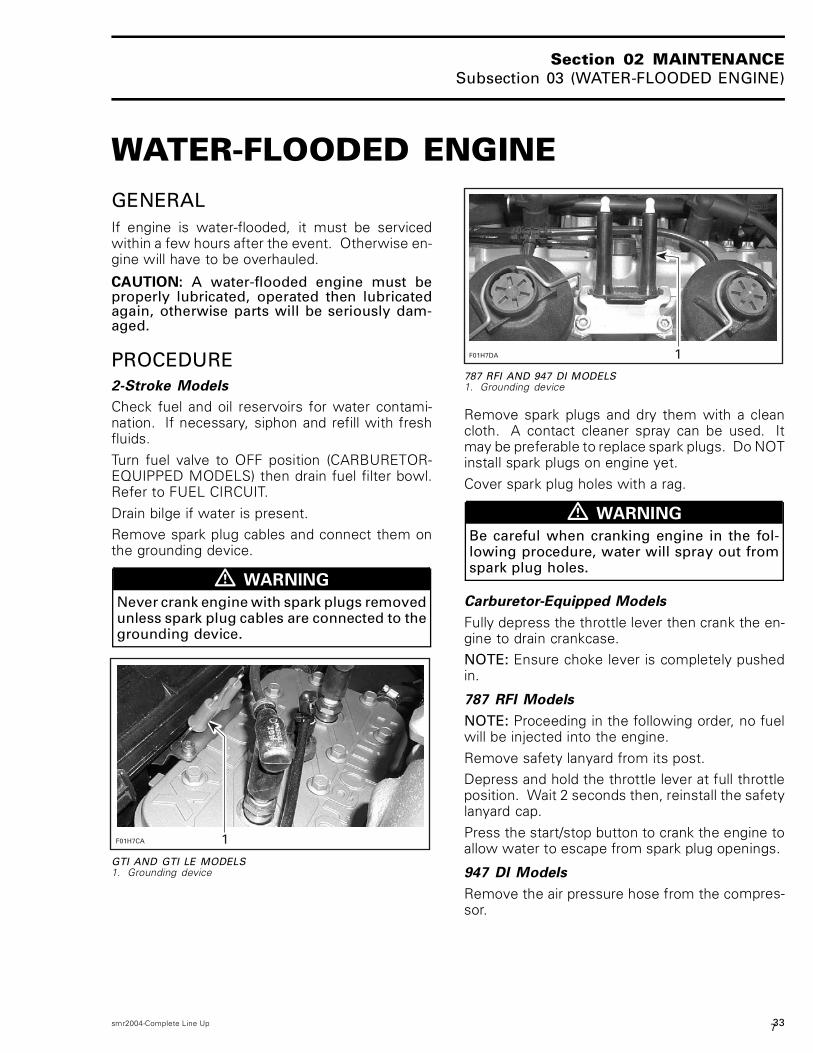
����;+)�
787 RFI AND 947 DI MODELS1. Grounding device
Remove spark plugs and dry them with a cleancloth. A contact cleaner spray can be used. Itmay be preferable to replace spark plugs. Do NOTinstall spark plugs on engine yet.Cover spark plug holes with a rag.
� WARNING
Be careful when cranking engine in the fol-lowing procedure, water will spray out fromspark plug holes.
Carburetor-Equipped Models
Fully depress the throttle lever then crank the en-gine to drain crankcase.NOTE: Ensure choke lever is completely pushedin.
787 RFI Models
NOTE: Proceeding in the following order, no fuelwill be injected into the engine.Remove safety lanyard from its post.Depress and hold the throttle lever at full throttleposition. Wait 2 seconds then, reinstall the safetylanyard cap.Press the start/stop button to crank the engine toallow water to escape from spark plug openings.
947 DI Models
Remove the air pressure hose from the compres-sor.
smr2004-Complete Line Up 337
Section 02 MAINTENANCESubsection 03 (WATER-FLOODED ENGINE)
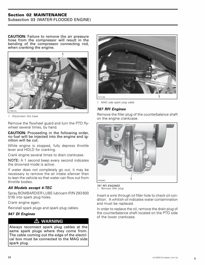
CAUTION: Failure to remove the air pressurehose from the compressor will result in thebending of the compressor connecting rod,when cranking the engine.
�
��*)���
1. Disconnect this hose
Remove the flywheel guard and turn the PTO fly-wheel several times, by hand.
CAUTION: Proceeding in the following order,no fuel will be injected into the engine and ig-nition will be cut.While engine is stopped, fully depress throttlelever and HOLD for cranking.Crank engine several times to drain crankcase.NOTE: A 1 second beep every second indicatesthe drowned mode is active.If water does not completely go out, it may benecessary to remove the air intake silencer thento lean the vehicle so that water can flow out fromthrottle bodies.
All Models except 4-TEC
Spray BOMBARDIER LUBE lubricant (P/N 293 600016) into spark plug holes.Crank engine again.Reinstall spark plugs and spark plug cables.
947 DI Engines
� WARNING
Always reconnect spark plug cables at thesame spark plugs where they come from.The cable coming out the edge of the electri-cal box must be connected to the MAG sidespark plug.
��+���� �
1. MAG side spark plug cable
787 RFI Engines
Remove the filler plug of the counterbalance shafton the engine crankcase.
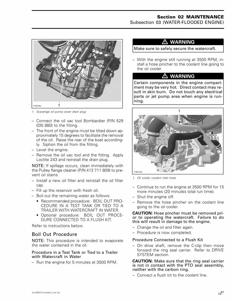
F07D06A1
787 RFI ENGINES1. Remove filler plug
Insert a wire through oil filler hole to check oil con-dition. A whitish oil indicates water contaminationand must be replaced.In order to replace the oil, remove the drain plug ofthe counterbalance shaft located on the PTO sideof the lower crankcase.
34 smr2004-Complete Line Up 8

Section 02 MAINTENANCESubsection 03 (WATER-FLOODED ENGINE)
F07D07A 1
787 RFI ENGINES1. Drain plug
Drain completely the crankcase oil of the coun-terbalance shaft. Reinstall drain plug with Loctite515.Add 30 mL (1 oz) of SAE 30 motor oil.Reinstall filler plug.
Carburetor-Equipped Models
Turn fuel valve to ON position.Start engine. It may be necessary to use thechoke. If engine does not start, repeat previoussteps as necessary.
787 RFI and 947 DI Models
Start engine according to normal starting proce-dure.
All Models except 4-TEC
CAUTION: To avoid starting motor overheat-ing, the cranking period should not exceed 5 -10 seconds and a rest period of 30 secondsshould be observed between cranking cycles.NOTE: If engine does not start after severalattempts, check ignition system for spark occur-rence. Refer to IGNITION SYSTEM for 717 and787 RFI engines and refer to ENGINE MANAGE-MENT for 947 DI engines.Check crankshaft if needed, it may be misalignedor deflected. Refer to BOTTOM END.After engine has started, spray BOMBARDIERLUBE lubricant for one minute through air intakesilencer while engine is running.
All Models except 947 DI and 4-TEC Models
����� �
� ��
717 AND 787 RFI ENGINES1. Air intake silencer2. Pull plug3. Spray BOMBARDIER LUBE here
947 DI Models
Spray, through hole of air intake silencer.NOTE: An increase of engine RPM may be no-ticed while spraying the lubricant in the air intakesilencer.
������� �
1. Partially pull tube out of air box to inject BOMBARDIER LUBElubricant or equivalent. Push tube in when finished
Run engine until it reaches its normal operatingtemperature.
CAUTION: Engine must be cooled using theflush kit.
4-TEC Models
Check fuel reservoir for water contamination. Ifnecessary, siphon and refill with fresh fuel.To limit damages to the engine, perform the fol-lowing procedure as soon as possible.Drain bilge if water is present.
smr2004-Complete Line Up 359

Section 02 MAINTENANCESubsection 03 (WATER-FLOODED ENGINE)
If it was submerged in salt water, spray bilge andall components with fresh water using a gardenhose to stop the salt corroding effect.
CAUTION: Never try to crank or start the en-gine. Water trapped in the intake manifoldwould enter the combustion chamber throughthe intake valves and may cause damage tothe engine.Whenever the engine is stopped, all the valvesclose thus preventing water from being ingestedin the engine.
Supercharged 4-TEC Engines
Inlet duct should be disconnected from super-charger inlet tube to validate presence of water.
���*)�0� � �
1. Inlet duct2. Inlet hose3. Outlet hose
If water is suspected to be in the supercharger,remove its outlet hose and siphon water out. En-sure that siphon tube is inserted to the lowestpoint in the supercharger.NOTE: Keep outlet hose disconnected and contin-ue procedures below. This way, when engine willbe started, possible water trapped in superchargerwill be pushed out. Then, the hose can be recon-nected.If necessary, remove supercharger housing.
All 4-TEC Engines
If water is suspected to be in the intake and theexhaust system, it must be drained as follows:Remove the intake manifold and drain it. Thensuck out the water from the intake valve ports.Refer to subsection INTAKE SYSTEM.
Remove the water from oil/air separator breatherhose.Remove the exhaust pipe and drain it. Then eitherremove the mufflers to drain them or siphon thewater out of them. Refer to subsection EXHAUSTSYSTEM.If water gets in the oil (oil will be milky), changethe engine oil and filter as follows.
Oil Change Procedure(water-contaminated oil)– Using the oil VAC (P/N 529 035 880), siphon oil
from reservoir through dipstick hole.
CAUTION: Never crank or start engine whensiphon tube is in dipstick hole. Never start en-gine when there is no oil in engine.– Remove the oil vac tool from the dipstick hole.– While in drowned engine mode, crank the en-
gine for 5 seconds.– Remove the oil filter cap and the oil filter.– Again, siphon oil from the reservoir.– Put a rag under the scavenge oil pump cover.– Remove the scavenge oil pump cover drain plug
and install a fitting (P/N 293 710 037).
��*)�6�
36 smr2004-Complete Line Up 10
Section 02 MAINTENANCESubsection 03 (WATER-FLOODED ENGINE)
���*)���
1. Scavenge oil pump cover drain plug
– Connect the oil vac tool Bombardier (P/N 529035 880) to the fitting.
– The front of the engine must be tilted down ap-proximately 15 degrees to facilitate the removalof the oil. Raise the rear of the boat according-ly. Siphon the oil from the fitting.
– Level the engine.– Remove the oil vac tool and the fitting. Apply
Loctite 243 and reinstall the drain plug.NOTE: If spillage occurs, clean immediately withthe Pulley flange cleaner (P/N 413 711 809) to pre-vent oil stains.– Install a new oil filter and reinstall the oil filter
cap.– Fill up the reservoir with fresh oil.– Boil out the remaining water as follows:
• Recommended procedure: BOIL OUT PRO-CEDURE IN A TEST TANK OR TIED TO ATRAILER WITH WATERCRAFT IN WATER.
• Optional procedure: BOIL OUT PROCE-DURE CONNECTED TO A FLUSH KIT.
Refer to instructions below.
Boil Out ProcedureNOTE: This procedure is intended to evaporatethe water contained in the oil.
Procedure in a Test Tank or Tied to a Trailerwith Watercraft in Water– Run the engine for 5 minutes at 3500 RPM.
� WARNING
Make sure to safely secure the watercraft.
– With the engine still running at 3500 RPM, in-stall a hose pincher to the coolant line going tothe oil cooler.
� WARNING
Certain components in the engine compart-ment may be very hot. Direct contact may re-sult in skin burn. Do not touch any electricalparts or jet pump area when engine is run-ning.
�
��*��?�
1. Oil cooler coolant inlet hose
– Continue to run the engine at 3500 RPM for 15more minutes (20 minutes total run time).
– Shut the engine off.– Remove the hose pincher on the coolant line
going to the oil cooler.
CAUTION: Hose pincher must be removed pri-or to operating the watercraft. Failure to dothis will result in damage to the engine.– Change the oil and filter again.– Procedure is now completed.
Procedure Connected to a Flush Kit– On drive shaft, remove the C-clip then move
forward the ring seal carrier. Refer to DRIVESYSTEM section.
CAUTION: Make sure that the ring seal carrieris not in contact with the PTO seal assembly,neither with the carbon ring.– Connect a flush kit to the coolant line.
smr2004-Complete Line Up 3711

Section 02 MAINTENANCESubsection 03 (WATER-FLOODED ENGINE)
CAUTION: Never run engine without supplyingwater to the exhaust cooling system when wa-tercraft is out of water.– Run the engine for 5 minutes at 3000 RPM.– With the engine still running at 3000 RPM, in-
stall a hose pincher to the coolant line going tothe oil cooler.
� WARNING
Certain components in the engine compart-ment may be very hot. Direct contact may re-sult in skin burn. Do not touch any electricalparts or jet pump area when engine is run-ning.
�
��*��?�
1. Oil cooler coolant inlet hose
– Continue to run the engine at 3000 RPM for 15more minutes (20 minutes total run time).
– Shut off the engine.– Remove the hose pincher on the coolant line
going to the oil cooler.
CAUTION: Hose pincher must be removed pri-or to operating the watercraft. Failure to dothis will result in damage to the engine.– Change the oil and filter again.– Move rearward the Ring Seal Carrier and rein-
stall the C-clip. Refer to DRIVE SYSTEM sec-tion.
Water in SuperchargerSupercharged 4-TEC Engines
If there was water in the oil and presence of wa-ter is suspected in the shaft and bearing area ofthe supercharger, it is recommended to take thesupercharger apart, dry all the components includ-ing the slip clutch and replace both ball bearings.Refer to INTAKE SYSTEM.
Finalizing the ProcedureAll 4-TEC Engines
The watercraft should be ridden as soon as possi-ble to dry it out.
38 smr2004-Complete Line Up 12

Section 02 MAINTENANCESubsection 04 (STORAGE)
STORAGEENGINE DRAININGAll Carburetor-Equipped Engines
Check engine drain hose (lowest hose of engine).Make sure there is no sand or other particles in itand that it is not obstructed so that water can exitthe engine. Clean hose and fitting as necessary.
CAUTION: Water in engine drain hose mustbe free to flow out, otherwise water could betrapped in engine. Should water freeze in en-gine, severe damage will occur. Check enginedrain hose for obstructions.
��+���� �
TYPICAL1. Engine drain hose
RFI Models
Disconnect the water supply hose used to coolthe magneto. It features a quick connect fitting.Press both tabs and pull fitting in order to discon-nect hose.This hose is located at the bottom of the magnetocover beside the engine support.
��+����
�
TYPICAL1. Press tabs here and disconnect hose
Water should flow out of the fitting (magneto cooling circuit) and hose (crankcase heat exchanger).Push and hold hose against bilge so that drainingcan take place.
�
�
��+����
1. Fitting2. Hose
smr2004-Complete Line Up 3913

Section 02 MAINTENANCESubsection 04 (STORAGE)
CAUTION: Water in heat exchanger systemmust be free to flow out. Should water freezein engine, severe damage will occur.Reconnect hose when done.
DI Models
Disconnect the quick connect fitting. Press bothtabs and pull fitting.NOTE: Illustration also shows air compressor line.
��*����
�
�
XP DI MODELS — DISCONNECT THIS HOSE1. Disconnect engine drain hose (crankcase cooling outlet)2. Air compressor drain line
Lower hose as necessary so that draining can takeplace.Reconnect hose when done.Also ensure air compressor drain line is not ob-structed. See illustration above. Clean as neces-sary.
PROPULSION SYSTEM
Jet PumpAll Models except 4-TEC Models
Lubricant in impeller shaft reservoir should bedrained. Reservoir should be cleaned and refilledwith SEA-DOO synthetic 75W90 GL5 polyesteroil. Refer to JET PUMP for proper procedure.
CAUTION: Use only SEA-DOO jet pump oil orequivalent synthetic gear oil, otherwise com-ponent service life could be reduced. Do notmix oil brands or types.
4-TEC Models
Verify jet pump grease for water contamination.Check for the presence of water in cone and bear-ing; if so, replace oil seal and sleeve.
CAUTION: Use only Bombardier jet pumpgrease or equivalent, otherwise componentsservice life could be reduced. Do not mixgrease brands or types.
PTO FlywheelAll 2-Stroke Models except XP DI
Remove PTO flywheel guard.Lubricate PTO flywheel at grease fitting with syn-thetic grease (P/N 293 550 010).
CAUTION: Do not lubricate excessively. Imme-diately stop when a slight movement is noticedon rubber boot.
���7��� �
1. Grease PTO flywheel
CAUTION: Never leave any clothing, tool orother objects near PTO flywheel and driveshaft.
40 smr2004-Complete Line Up 14

Section 02 MAINTENANCESubsection 04 (STORAGE)
SEAL CARRIERXP DI Models
Lubricate seal carrier of drive shaft support withsynthetic grease. Stop lubricating when grease isjust coming out of seal.
��*����
�
1. Grease seal carrier
FUEL SYSTEMAll Models
Verify fuel system. Check fuel hoses and carbure-tor(s), if so equipped, for leaks. Replace damagedhoses or clamps if necessary.Sea-Doo Fuel Stabilizer (P/N 413 408 600) or equiv-alent should be added in fuel tank to prevent fu-el deterioration and, if so equipped, carburetor(s)gumming. Follow manufacturer's instructions forproper use.On RFI and DI models, fill up fuel tank completely.Ensure there is no water inside fuel tank.
CAUTION: Should any water be trapped insidefuel tank, severe internal damage will occur tothe fuel injection system (if so equipped).
CAUTION: Fuel stabilizer should be addedprior to engine lubrication to ensure fuel sys-tem components protection against varnishdeposits.
� WARNING
Fuel is inflammable and explosive undercertain conditions. Always work in a wellventilated area. Do not smoke or allow openflames or sparks in the vicinity. Fuel tankmay be pressurized, slowly turn cap whenopening. Never use an open flame to checkfuel level. When fueling, keep watercraftlevel. Do not overfill or top off the fuel tankand leave watercraft in the sun. As tem-perature increases, fuel expands and mightoverflow. Always wipe off any fuel spillagefrom the watercraft. Periodically inspect fuelsystem. Always turn the fuel tank valve (if soequipped) to OFF position when storing thewatercraft.
Carburetor-Equipped Models
Always turn the fuel valve to OFF position whenstoring the watercraft.
ENGINE OIL CHANGE AND FILTER4-TEC Engines
Change engine oil and filter. Refer to LUBRICA-TION in ENGINE section.
All Models
COOLING SYSTEM FLUSHINGAND ENGINE INTERNALLUBRICATIONCooling system (exhaust cooling system on 4-TECmodels) has to be flushed with fresh water to pre-vent salt, sand or dirt accumulation which will clogwater passages.Engine must be lubricated to prevent corrosion oninternal parts.For proper procedure, refer to FLUSHING ANDLUBRICATION.
ENGINE LUBRICATION4-TEC Engines
Engine must be lubricated to prevent corrosion oninternal parts.
smr2004-Complete Line Up 4115

Section 02 MAINTENANCESubsection 04 (STORAGE)
Fogging of the engine is recommended at the endof the season and before any extended storageperiod to provide additional corrosion protection.This will lubricate the engine intake valves, thecylinders and the exhaust valves.To fog the engine, proceed as follows:– Remove the two bolts that hold the fuel rail on.– Remove the rail along with the three fuel injec-tors.– Spray liberally BOMBARDIER LUBE lubricant in-to the intake ports.– Crank engine several times while keeping throt-tle fully depressed (drown engine mode) to dis-tribute lubricant in cylinders, on intake valves andexhaust valves.– Carefully inspect O-rings condition before rein-stalling fuel injectors. Replace O-rings with newones if damaged. Lubricate O-rings with injectionoil prior to installing.– Reinstall the injectors.– Apply Loctite 243 and torque the two bolts to10 N•m (89 lbf•in) that hold the fuel rail on.– Make sure there is no leak at injectors whencranking the engine in the upcoming steps.
� WARNING
If a leak is present, immediately stop the en-gine. Do not start engine until the leak is re-paired.
� WARNING
At preseason preparation, ensure to performa fuel pressure test and ensure there is noleak. Also run engine and check for leaks.Refer to ENGINE MANAGEMENT section.
All Models
BATTERYFor battery removal, cleaning and storage, refer toCHARGING SYSTEM.
WATERCRAFT CLEANINGClean the bilge with hot water and mild detergentor with bilge cleaner. Rinse thoroughly. Lift frontend of watercraft to completely drain bilge. If anyrepairs are needed to body or to the hull, touchup paint and Gelcote® repair kit are available. Re-place damaged labels/decals.Wash the body with soap and water solution (onlyuse mild detergent). Rinse thoroughly with freshwater. Remove marine organisms from the hull.Apply a nonabrasive wax.
CAUTION: Never clean fiberglass and plasticparts with strong detergent, degreasing agent,paint thinner, acetone, etc.If the watercraft is to be stored outside, cover itwith an opaque tarpaulin to prevent sun rays andgrime from affecting the plastic components, wa-tercraft finish as well as preventing dust accumu-lation.
CAUTION: The watercraft must never be left inwater for storage. Never leave the watercraftstored in direct sunlight.
ADDITIONAL RECOMMENDEDPROTECTIONAll 2-Stroke Models
In cool regions (where freezing point may be en-countered), cooling system should be filled pureantifreeze.
CAUTION: Antifreeze must be fed in cool-ing system. Otherwise remaining water willfreeze. If antifreezing is not performed ad-equately engine/exhaust system may freezeand cause severe damage. Always use ethy-lene glycol antifreeze containing corrosioninhibitors specifically recommended for alu-minum engines.
CAUTION: Use only undiluted antifreeze (100%concentration). The pre-mixed antifreezeavailable from Bombardier Recreational Prod-ucts Inc. is not suitable for this particular appli-cation. Its concentration will be reduced whenmixed with remaining water trapped in waterjackets. Always use ethylene glycol antifreezecontaining corrosion inhibitors specificallyrecommended for aluminum engines. Neveruse antifreeze for RV (recreational vehicles).
42 smr2004-Complete Line Up 16

Section 02 MAINTENANCESubsection 04 (STORAGE)
NOTE: When available, it is recommended touse biodegradable antifreeze compatible withinternal combustion aluminum engines. This willcontribute to protect the environment.NOTE: The engine will not have to run during thisoperation but should have been ran before, to ex-haust as much water as possible, from coolingsystem components.
All 2-Stroke Models except DI
NOTE: This procedure requires approximately2.5 L (2.6 U.S. qt) of antifreeze.
Hose Pinchers InstallationSome hoses have to be plugged to prevent drain-ing, before filling cooling system jackets with theantifreeze.
All 2-Stroke Models except DI
Install hose pinchers at the following locations.
�
��+�� �
GTI AND GTI LE MODELS — 717 ENGINES1. Engine drain hose
�� ���� �
RFI MODELS — 787 ENGINES1. Engine drain hose
NOTE: On RFI models, make sure the hose isproperly connected to the magneto cover.
��+����
�
RFI MODELS — 787 ENGINES1. Fitting properly connected
smr2004-Complete Line Up 4317
Section 02 MAINTENANCESubsection 04 (STORAGE)
Install hose pincher on injection hose going totuned pipe.
��+���� �
GTI AND GTI LE MODELS — 717 ENGINES1. Hose pincher on injection hose going to tuned pipe
��+���� �
717 AND 787 RFI ENGINES1. Engine water outlet hose
Hose DisconnectionSome hoses have to be disconnected. Discon-nect hoses at the following location.
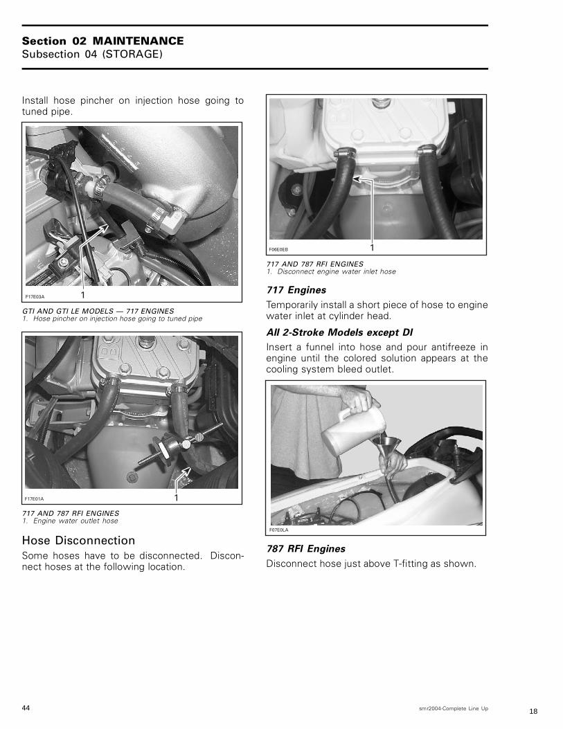
��,���� �
717 AND 787 RFI ENGINES1. Disconnect engine water inlet hose
717 Engines
Temporarily install a short piece of hose to enginewater inlet at cylinder head.
All 2-Stroke Models except DI
Insert a funnel into hose and pour antifreeze inengine until the colored solution appears at thecooling system bleed outlet.
��+����
787 RFI Engines
Disconnect hose just above T-fitting as shown.
44 smr2004-Complete Line Up 18

Section 02 MAINTENANCESubsection 04 (STORAGE)
�� ���� ��
TYPICAL1. Hose connecting to cylinder head inlet fitting2. Disconnect hose above T-fitting
787 RFI Engines
Install a hose pincher just below T-fitting.
�� ���� �
1. Hose pincher below T-fitting
Pour approximately 300 mL (10 oz) of antifreeze inthe water regulator valve supply hose to allow an-tifreeze flowing through the valve and into mufflerto protect them.Reconnect hose to T-fitting and remove hosepincher (if applicable).
All 2-Stroke Models except DI
Remove temporary hose on 717 engines and re-connect engine water outlet hose.Remove remaining hose pinchers.
Most of the antifreeze will drain out when remov-ing the hose pinchers. Use a container to recoverit. DISPOSE ANTIFREEZE AS PER YOUR LOCALLAWS AND REGULATIONS.NOTE: Although antifreeze will mainly drain out,the antifreeze has mixed with the water that waspossibly trapped in the water jackets and thus pre-venting freezing problems.At preseason preparation, drain the remaining an-tifreeze from cooling system prior to using the wa-tercraft. Ensure no hose pincher was forgotten atstorage.
XP DI Models
NOTE: This procedure requires approximately2.8 L (3 U.S. qt) of antifreeze.
Hose Pinchers InstallationSome hoses have to be plugged to prevent drain-ing, before filling cooling system jackets with theantifreeze.Install hose pinchers at the following location:
��*��.�
�
�
XP DI MODELS1. Water inlet hose2. Engine cylinder drain hose (coming from underneath engine)
smr2004-Complete Line Up 4519

Section 02 MAINTENANCESubsection 04 (STORAGE)
��*��6�
�
XP DI MODELS1. Water outlet hose underneath tuned pipe
Hose DisconnectionDisconnect the bottom hose at the water regulatorvalve on muffler.
��*���� �
XP DI MODELS1. Disconnect the bottom hose from water regulator valve
Temporarily install a hose of approximately 1 m(3 ft) with an internal diameter of 12.7 mm (1/2 in)over the previously disconnected hose.
AntifreezeInsert a funnel into the temporary hose.Ensure to hold the funnel approximately 1 m (3 ft)above the deck when pouring the antifreeze tocreate enough pressure so that it flows properly.
��*��/�
�
A. 1 m (3 ft) to ease antifreeze flow
Pour antifreeze in engine until the colored solutionappears at cooling system bleed outlet.At this point, install a hose pincher on bleed outlethose.
46 smr2004-Complete Line Up 20

Section 02 MAINTENANCESubsection 04 (STORAGE)
��*����
�
XP DI MODELS1. Bleed outlet hose
Continue to pour until antifreeze appears at the en-gine drain hose (crankcase cooling outlet). Then,install a hose pincher on this hose.
��*��A�
�
1. Engine drain hose (crankcase cooling outlet)
Continue to pour until antifreeze flows in air com-pressor water outlet hose.
��*����
�
XP DI MODELS1. Air compressor water outlet hose
The pouring operation is over.Remove pinchers in this order to allow proper flowof antifreeze.
smr2004-Complete Line Up 4721

Section 02 MAINTENANCESubsection 04 (STORAGE)
NOTE: Most of the antifreeze will drain out whenremoving the hose pinchers. Use a container torecover it. DISPOSE ANTIFREEZE AS PER YOURLOCAL LAWS AND REGULATIONS.1) Bleed outlet hose.2) Engine drain hose (crankcase cooling cover
outlet).3) Engine cylinder drain hose.4) Water outlet hose.5) Water inlet hose.Install a temporary hose on the open fitting of thewater regulator valve.Pour approximately 200 mL (7 oz) of antifreezein the temporary hose to allow antifreeze flowingthrough the water regulator valve and into mufflerto protect them.Remove temporary hoses and reinstall the factoryhose to water regulator valve.NOTE: Although antifreeze will mainly drain out,the antifreeze has mixed with the water that waspossibly trapped in the water jackets and thus pre-venting freezing problems.At preseason preparation, drain the remaining an-tifreeze from cooling system prior to using the wa-tercraft. Ensure no hose pincher was forgotten atstorage.
4-TEC Engines
Refer to the COOLING SYSTEM section.Antifreeze should be replaced for the storage pe-riod to prevent antifreeze deterioration.Make sure to perform an antifreeze density test.
CAUTION: Improper antifreeze mixture mightallow freezing of the liquid in the cooling sys-tem if vehicle is stored in area where freezingpoint is reached. This would seriously damagethe engine. Failure to replace the antifreezefor storage may allow its degradation thatcould result in poor cooling when engine willbe used.
All Models
ANTICORROSION TREATMENTWipe off any residual water in the engine compart-ment.Spray BOMBARDIER LUBE lubricant over allmetallic components in engine compartment.
Lubricate the throttle cable with BOMBARDIERLUBE lubricant.
4-TEC Models
Apply an anticorrosion product on drive shaft. Re-fer to PROPULSION.
All Models
The seat should be partially left opened duringstorage (the engine cover for the XP DI models).This will avoid engine compartment condensationand possible corrosion.
CHECKLIST
OPERATION ✔
Check engine drain hose(s).
Drain and clean impeller shaft reservoir (except4-TEC engines).
Verify jet pump grease (4-TEC engines)
Lubricate PTO flywheel or seal carrier (except4-TEC engines).
Verify fuel system.
Add Sea-Doo fuel stabilizer.
Flush the cooling system (except 4-TECengines).
Flush the exhaust cooling system by running4-TEC Engines the engine (4-TEC engines).
Change engine oil and filter (4-TEC engines).
Lubricate the engine.
Remove, clean and store the battery.
Clean the bilge.
Wash the body.
Add antifreeze solution to the cooling system (incool regions) (except 4-TEC engines).
Replace antifreeze. Check solutionconcentration in the cooling system (in coolregions) (4-TEC engines).
Spray BOMBARDIER LUBE over all metalliccomponents in engine compartment and inthrottle cable.
Spray BOMBARDIER LUBE in oil injection pumpcable (except 4-TEC engines).
48 smr2004-Complete Line Up 22