flue manual (maxima) (v3) (page 1) - gasboilerforums.com · modena / domina f24 / f30 sigma 20-40 /...
TRANSCRIPT


1
CONTENTS
2 - 5
6 & 7
8 & 9
10
11 & 12
13 & 14
Page No.
MODENA / DOMINA
F24 / F30
SIGMA 20-40 / SIGMA 40-60 / SIGMA 60-100
TEMPRA 12 / 18
TEMPRA 24 / TEMPRA 30
ARENA 30A / ARENA 30C
15 & 16MAXIMA 27C/27S AND MAXIMA 35C/35S
SECTION 1 Boiler Dimensions and Minimum Clearances
18 - 21
22 - 25
26 & 27
28 & 29
30 & 31
32 - 35
Page No.
MODENA / DOMINA
17Introduction
F24 / F30
SIGMA 20-40 / SIGMA 40-60
SIGMA 60-100
TEMPRA 12 / 18
TEMPRA 24 / TEMPRA 30
36ARENA 30A / ARENA 30C
37 & 38MAXIMA 27C/27S AND MAXIMA 35C/35S
SECTION 2 Standard Flue Applications
39
40
41 & 42
43 & 44
45
46 - 49
Page No.
Resistance Factors / Permissible Flue Lengths (concentric)
Resistance Factors / Permissible Flue Lengths (two pipe)
Flue Restrictor Sizes
Example Flueing Diagrams - horizontal concentric flues
Example Flueing Diagrams - vertical concentric flues
Example Flueing Diagrams - two pipe system
50S.E. Duct / ‘U’ Duct
51 & 52Flue Terminal Positions
53 - 61Accessories for Flue Systems (Standard Boilers & Condensing Boilers)
SECTION 3 Flueing Options
The Gas Safety Regulations (Installation & Use)
N.B. Flues must be installed strictly in accordance with:
The Building Regulations
Local Building Regulations
The Building Standards (Scotland - Consolidated) Regulations
B.S. 5440 Part 1 - Flues
British Standard Codes of Practice:
B.S. 5440 Part 2 - Air Supply / Ventilation
B.S. 6798 - Installation of Gas Fired Hot Water Boilers
PLEASE NOTE: THIS IS A FLUE OPTION BOOK. FOR MORE DETAILED INFORMATION PLEASE REFER TO THERELEVANT BOILER INSTALLATION MANUAL.

BOILER DIMENSIONS AND MINIMUM CLEARANCES
MODENA 80E
2
1 3 4 5
15012012070
110
80 8080
460
Top view
1149560609536
100
720
725
16025
10
100270
460
175100
Bottom viewed from above
Distance between connections
95
60 120280
26
65
190 270
Top
Minimum Clearances
Sides
Front
Bottom
* 50mm refers to minimum distance between any openable/removable panel (i.e. kitchen unit door).A minimum 600mm must be available for servicing access.
200mm
MODENA 80E
5mm
50mm*
200mm
Key
1 - 3/4” central heating flow outlet (22mm with isolation valve fitted)
2 - 1/2” domestic hot water flow outlet(15mm connector)
3 - 1/2” gas inlet(22mm with isolation valve fitted)
4 - 1/2” domestic cold water inlet(15mm with isolation valve fitted)
5 - 3/4” central heating return inlet(22mm with isolation valve fitted)
6 - 1/2” Pressure relief outlet
TOP FLUE ONLY

BOILER DIMENSIONS AND MINIMUM CLEARANCES
MODENA 102
3
733
460
430
105
14
362
200
720
65
Ø60
95
Ø10
0
189
Distance between connections36 95 60 60 155 54
175
Bottom viewed from above
189
460
Top view
120120
200
110
80
110
543261
Top
Minimum Clearances
Sides
Front
Bottom
* 50mm refers to minimum distance between any openable/removable panel (i.e. kitchen unit door).A minimum 600mm must be available for servicing access.
200mm
MODENA 102
5mm
50mm*
200mm
Key
1 - 3/4” central heating flow outlet (22mm with isolation valve fitted)
2 - 1/2” domestic hot water flow outlet(15mm connector)
3 - 1/2” gas inlet(22mm with isolation valve fitted)
4 - 1/2” domestic cold water inlet(15mm with isolation valve fitted)
5 - 3/4” central heating return inlet(22mm with isolation valve fitted)
6 - 1/2” Pressure relief outlet
TOP FLUE ONLY

BOILER DIMENSIONS AND MINIMUM CLEARANCES
DOMINA 80N
4
Top view
Distance between connections
178
190 270
Bottom viewed from above
272
760
249
98
609536 60 95
460
100
727
114
160100 25 150 25
53 4261
Top
Minimum Clearances
Sides
Front
Bottom
* 50mm refers to minimum distance between any openable/removable panel (i.e. kitchen unit door).A minimum 600mm must be available for servicing access.
100mm
DOMINA 80N
5mm
50mm*
200mm
Key
1 - 3/4” central heating flow outlet (22mm with isolation valve fitted)
2 - 1/2” domestic hot water flow outlet(15mm connector)
3 - 1/2” gas inlet(22mm with isolation valve fitted)
4 - 1/2” domestic cold water inlet(15mm with isolation valve fitted)
5 - 3/4” central heating return inlet(22mm with isolation valve fitted)
6 - 1/2” Pressure relief outlet
REAR FLUE AS STANDARD

BOILER DIMENSIONS AND MINIMUM CLEARANCES
DOMINA 102 N
5
363
15 43076
015
692
36 15595 5460
2
531
60
189
175
1 3 5
2
6
Bottom viewed from above
4
4
Top view
165
230 230
Top
Minimum Clearances
Sides
Front
Bottom
* 50mm refers to minimum distance between any openable/removable panel (i.e. kitchen unit door).A minimum 600mm must be available for servicing access.
100mm
DOMINA 102 N
5mm
50mm*
200mm
Key
1 - 3/4” central heating flow outlet (22mm with isolation valve fitted)
2 - 1/2” domestic hot water flow outlet(15mm connector)
3 - 1/2” gas inlet(22mm with isolation valve fitted)
4 - 1/2” domestic cold water inlet(15mm with isolation valve fitted)
5 - 3/4” central heating return inlet(22mm with isolation valve fitted)
6 - 1/2” Pressure relief outlet
REAR FLUE AS STANDARD

BOILER DIMENSIONS AND MINIMUM CLEARANCES
FERROLI F24
6
Top view
Distance between connections
178
190 270
Bottom viewed from above
272
760
249
98
609536 60 95
460
10072
7
114
160100 25 150 25
8480 80
12070 120 15011
0
53 421 6
65
Top
Minimum Clearances
Sides
Front
Bottom
* 50mm refers to minimum distance between any openable/removable panel (i.e. kitchen unit door).A minimum 600mm must be available for servicing access.
200mm (100mm IF USING REAR FLUE)
F24
5mm
50mm*
200mm
Key
1 - 3/4” central heating flow outlet (22mm with isolation valve fitted)
2 - 1/2” domestic hot water flow outlet(15mm connector)
3 - 1/2” gas inlet(22mm with isolation valve fitted)
4 - 1/2” domestic cold water inlet(15mm with isolation valve fitted)
5 - 3/4” central heating return inlet(22mm with isolation valve fitted)
6 - 1/2” Pressure relief outlet
TOP FLUE STANDARD - REAR FLUE OPTIONAL
BOILER DIMENSIONS AND MINIMUM CLEARANCES
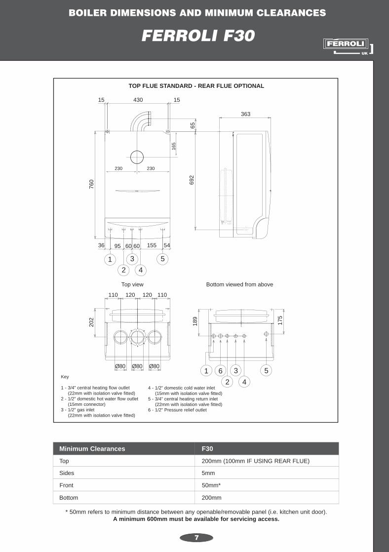
FERROLI F30
7
363
65
15 430
760
15
692
36 15595 5460
2
531
60
189
175
1 3 5
2
6
Bottom viewed from above
4
4
202
110
Ø80 Ø80 Ø80
120 120110
Top view
165
230 230
Top
Minimum Clearances
Sides
Front
Bottom
* 50mm refers to minimum distance between any openable/removable panel (i.e. kitchen unit door).A minimum 600mm must be available for servicing access.
200mm (100mm IF USING REAR FLUE)
F30
5mm
50mm*
200mm
Key
1 - 3/4” central heating flow outlet (22mm with isolation valve fitted)
2 - 1/2” domestic hot water flow outlet(15mm connector)
3 - 1/2” gas inlet(22mm with isolation valve fitted)
4 - 1/2” domestic cold water inlet(15mm with isolation valve fitted)
5 - 3/4” central heating return inlet(22mm with isolation valve fitted)
6 - 1/2” Pressure relief outlet
TOP FLUE STANDARD - REAR FLUE OPTIONAL

25
A
25
B 85
147
15
50
120 50
D
C
132
50
200
21
220
3
4
600
620
200
78
5
Right side view
Front view
Top view
BOILER DIMENSIONS AND MINIMUM CLEARANCES
8
SIGMA 20-40 AND SIGMA 40-60
Top
Minimum Clearances
Sides
Front
Bottom
* 50mm refers to minimum distance between any openable/removable panel (i.e. kitchen unit door).A minimum 600mm must be available for servicing access.
200mm
SIGMA 20-40 / SIGMA 40-60
5mm
50mm*
200mm
Amm
Dmm
Bmm
Cmm
Sigma 20-40 603553320
Sigma 40-60 5530133400
Model
Key
1 - Ø 22mm flow outlet2 - Ø 22mm return inlet3 - Ø 15mm gas inlet4 - Rear air inlet/flue outlet5 - Top air inlet/flue outlet
REAR FLUE AS STANDARD - TOP FLUE OPTIONAL

325 35
207
5542
58450
643
132,5 162,5105
25 25
200 250
450
115
200
360
115
1
2
3
3
4
2660
1 2
Right side viewFront view
Top view19
0
5
BOILER DIMENSIONS AND MINIMUM CLEARANCES
9
Top
Minimum Clearances
Sides
Front
Bottom
* 50mm refers to minimum distance between any openable/removable panel (i.e. kitchen unit door).A minimum 600mm must be available for servicing access.
200mm
SIGMA 60-100
5mm
50mm*
200mm
REAR FLUE AS STANDARD - TOP FLUE OPTIONAL
SIGMA 60-100
Key
1 - Ø 22mm flow outlet2 - Ø 22mm return inlet3 - Ø 15mm gas inlet4 - Rear air inlet/flue outlet5 - Top air inlet/flue outlet

105 1752595
165
720
12485
400
115
13
36
160
155
36
98
2 31
155 12485
110
160
Ø100Ø60
TOP VIEW
BOTTOM VIEW
16.5
270
98
FRONT VIEW
RIGHT SIDE VIEW
Key
1 - 3/4” Central heating outlet (22mm with isolation valve fitted)
2 - 1/2” Gas inlet(22mm with isolation valve fitted)
3 - 3/4” Central heating inlet(22mm with isolation valve fitted)
BOILER DIMENSIONS AND MINIMUM CLEARANCES
TEMPRA 12-18
10
Top
Minimum Clearances
Sides
Front
Bottom
* 50mm refers to minimum distance between any openable/removable panel (i.e. kitchen unit door).A minimum 600mm must be available for servicing access.
200mm (100mm IF USING REAR FLUE)
TEMPRA 12-18
5mm
50mm*
200mm
TOP FLUE AS STANDARD - REAR FLUE OPTIONAL

BOILER DIMENSIONS AND MINIMUM CLEARANCES
TEMPRA 24
11
760
190
36 114155155
272
175
98
15515536
460
98
114
160100 25 150 25
Ø80Ø80 Ø80
12070 120 150
110
321 4
965
706
FRONT VIEW
LEFT SIDE VIEW
BOTTOM VIEWED FROM ABOVETOP VIEW
Top
Minimum Clearances
Sides
Front
Bottom
* 50mm refers to minimum distance between any openable/removable panel (i.e. kitchen unit door).A minimum 600mm must be available for servicing access.
200mm (100mm IF USING REAR FLUE)
TEMPRA 24
5mm
50mm*
200mm
TOP FLUE AS STANDARD - REAR FLUE OPTIONAL
Key
1 - 3/4” central heating flow outlet (22mm with isolation valve fitted)
2 - 1/2” gas inlet(22mm with isolation valve fitted)
3 - 3/4” central heating return inlet(22mm with isolation valve fitted)
4 - 1/2” Pressure relief outlet

BOILER DIMENSIONS AND MINIMUM CLEARANCES
TEMPRA 30
12
363
65
15 430
760
15
692
460
36 155 215 54
321
189
175
1 2 3
202
110
Ø80 Ø80 Ø80
120 120110
165
FRONT VIEW
LEFT SIDE VIEW
BOTTOM VIEWED FROM ABOVE
TOP VIEW
4
Top
Minimum Clearances
Sides
Front
Bottom
* 50mm refers to minimum distance between any openable/removable panel (i.e. kitchen unit door).A minimum 600mm must be available for servicing access.
200mm (100mm IF USING REAR FLUE)
TEMPRA 30
5mm
50mm*
200mm
TOP FLUE AS STANDARD - REAR FLUE OPTIONAL
Key
1 - 3/4” central heating flow outlet (22mm with isolation valve fitted)
2 - 1/2” gas inlet(22mm with isolation valve fitted)
3 - 3/4” central heating return inlet(22mm with isolation valve fitted)
4 - 1/2” Pressure relief outlet
BOILER DIMENSIONS AND MINIMUM CLEARANCES
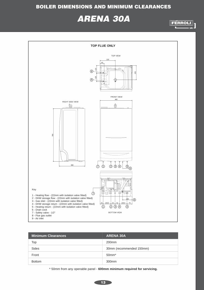
ARENA 30A
13
205
220
60
110
120
8
9
73109,56262109,544
139
368
760
460
1 2 3 4 56
7
FRONT VIEW
RIGHT SIDE VIEW
BOTTOM VIEW
TOP VIEW
1 2 3 4 5
6
7
Top
Minimum Clearances
Sides
Front
Bottom
* 50mm from any openable panel - 600mm minimum required for servicing.
200mm
ARENA 30A
30mm (recommended 150mm)
50mm*
300mm
TOP FLUE ONLY
Key
1 - Heating flow - (22mm with isolation valve fitted)2 - DHW storage flow - (22mm with isolation valve fitted)3 - Gas inlet - (22mm with isolation valve fitted)4 - DHW storage return - (22mm with isolation valve fitted)5 - Heating return - (22mm with isolation valve fitted)6 - Drain cock7 - Safety valve - 1/2”8 - Flue gas outlet9 - Air inlet

BOILER DIMENSIONS AND MINIMUM CLEARANCES
ARENA 30C
14
60
220
205
110
120
460
760
368
739576,576,59544
108
50 68
1 2 3 4 56
8
9
7
BOTTOM VIEW
1 2 3 4 5
6
7
FRONT VIEW
RIGHT SIDE VIEW
TOP VIEW
Top
Minimum Clearances
Sides
Front
Bottom
* 50mm from any openable panel - 600mm minimum required for servicing.
200mm
ARENA 30C
30mm (recommended 150mm)
50mm*
300mm
TOP FLUE ONLY
Key
1 - Heating flow - (22mm with isolation valve fitted)2 - DHW outlet - (15mm with connector fitted)3 - Gas inlet - (22mm with isolation valve fitted)4 - Cold water inlet - (15mm with isolation valve fitted)5 - Heating return - (22mm with isolation valve fitted)6 - Drain cock7 - Safety valve - 1/2”8 - Flue gas outlet9 - Air inlet
BOILER DIMENSIONS AND MINIMUM CLEARANCES
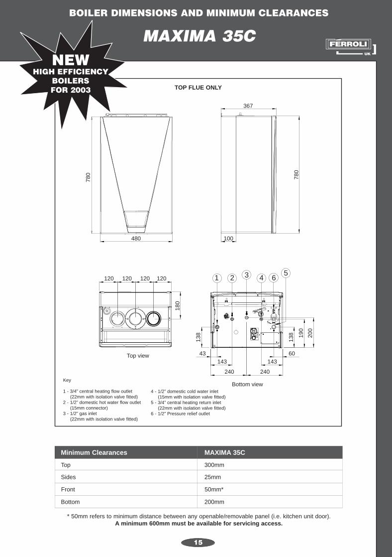
MAXIMA 35C
15
367
780
780
180
138
138 19
0
200
100480
Top view
64321120 120 120 120
240 240
143 14343 60
Bottom view
5
Top
Minimum Clearances
Sides
Front
Bottom
* 50mm refers to minimum distance between any openable/removable panel (i.e. kitchen unit door).A minimum 600mm must be available for servicing access.
300mm
MAXIMA 35C
25mm
50mm*
200mm
TOP FLUE ONLY
Key
1 - 3/4” central heating flow outlet (22mm with isolation valve fitted)
2 - 1/2” domestic hot water flow outlet(15mm connector)
3 - 1/2” gas inlet(22mm with isolation valve fitted)
4 - 1/2” domestic cold water inlet(15mm with isolation valve fitted)
5 - 3/4” central heating return inlet(22mm with isolation valve fitted)
6 - 1/2” Pressure relief outlet

BOILER DIMENSIONS AND MINIMUM CLEARANCES
MAXIMA 27C, 27S, AND 35S
16
Top view Bottom view
Top
Minimum Clearances
Sides
Front
Bottom
MAXIMA 27C, 27S AND 35S
DETAILS
TO
FOLLOW

17
max 0.84mmin 0.54m
max 0.84mmin 0.54m
Typical Top Flue - Rear OutletTypical Top Flue - Side Outlet
100 / 60 CONCENTRIC TELESCOPIC FLUE (0.84m)100 / 60 APPLIANCE BEND - 90deg.
Rear Outlet Max. Length 1m N.B. No flue restictor required for rear outlet
100 / 60 CONCENTRIC FLUE (NON-TELESCOPIC) (0.75m)
max 0.84mmin 0.54m
0.75m
Non-StandardTop Flue - Side Outlet
Available
TOP: MODENA TOP FLUE OUTLET
BOTTOM: DOMINA REAR FLUE OUTLET
Details of Standard Top and Rear Flue kits for the current range of Férroli Boilersshowing items included in each STANDARD FLUE KIT.
EXAMPLES:
FERROLI FLUE APPLICATIONS

FLUE APPLICATIONS
MODENA 80 / 102
18
STANDARD FLUE KIT (TOP FLUE ONLY)CODE: 1KWMA07Y Includes: 1-0.84m Telescopic flue
1-Appliance Bend
NON-STANDARD FLUE APPLICATIONS; MODENA (See “FLUE OPTIONS”)
max 0.84mmin 0.54m
max 0.84mmin 0.54m
Typical Top Flue - Rear OutletTypical Top Flue - Side Outlet
100 / 60 CONCENTRIC TELESCOPIC FLUE (0.84m)100 / 60 APPLIANCE BEND - 90deg.
Horizontal Vertical Horizontal Vertical
Options 100mm Concentric 125mm Concentric80mm Two
Pipe System
MaximumEquivalentdistance
3m 4m 5m 5m48m - Mod 80
50m - Mod 102

FLUE APPLICATIONS
DOMINA 80
19
STANDARD REAR FLUE KIT Includes: 1-0.75m Flue (non-telescopic)CODE: 823204
Rear Outlet Max. Length 1m N.B. No flue restictor required for rear outlet
100 / 60 CONCENTRIC FLUE (NON-TELESCOPIC) (0.75m)
0.75m
BACK PLATE
SEALS
max 0.84mmin 0.54m
Non-StandardTop Flue - Side Outlet
Available
NON-STANDARD FLUE APPLICATIONS; DOMINA (See “FLUE OPTIONS”)
Rear Flue Application
Maximum Flue Length
DOMINA 80
= 1m
REAR MOUNTING PLATE AND SEALSSUPPLIED IN BOILER CARTON

FLUE APPLICATIONS
DOMINA 102
20
STANDARD REAR FLUE KITCODE: 823204 Includes: 1-0.75m Flue (non-telescopic)
Rear Outlet Max. Length 1m N.B. No flue restictor required for rear outlet
100 / 60 CONCENTRIC FLUE (NON-TELESCOPIC) (0.75m)
0.75m
max 0.84mmin 0.54m
Non-StandardTop Flue - Side Outlet
Available
NON-STANDARD FLUE APPLICATIONS; DOMINA (See “FLUE OPTIONS”)
Rear Flue Application
Maximum Flue Length
DOMINA 102
= 1m

FLUE APPLICATIONS
DOMINA 80 / 102
21
TOP FLUE KIT OPTIONCODE: 1KWMA07Y Includes: 1-0.84m telescopic flue; 1-Appliance BendCODE: 1KWMR82A Includes: 1-Fan Adaptor; 2-Air Intake Plugs and Seals
NON-STANDARD FLUE APPLICATIONS; DOMINA 80 / 102 (See “FLUE OPTIONS”)
max 0.84mmin 0.54m
max 0.84mmin 0.54m
Typical Top Flue - Side OutletTypical Top Flue - Rear Outlet
100 / 60 CONCENTRIC TELESCOPIC FLUE (0.84m)
FAN ADAPTORAIR INTAKE PLUGS AND SEALS
100 / 60 APPLIANCE BEND - 90deg.
Horizontal Vertical Horizontal Vertical
Options 100mm Concentric 125mm Concentric80mm Two
Pipe System
MaximumEquivalentdistance
3m 4m 5m 5m48m - Dom 80
50m - Dom 102

FLUE APPLICATIONS
FERROLI F24
22
STANDARD TOP FLUE KITCODE: 1KWMA07Y Includes: 1-0.84m telescopic flue
1-Appliance Bend
NON-STANDARD FLUE APPLICATIONS; FERROLI F24 (See “FLUE OPTIONS”)
max 0.84mmin 0.54m
max 0.84mmin 0.54m
Typical Top Flue - Side OutletTypical Top Flue - Rear Outlet
100 / 60 CONCENTRIC TELESCOPIC FLUE (0.84m)100 / 60 APPLIANCE BEND - 90deg.
Horizontal Vertical Horizontal Vertical
Options 100mm Concentric 125mm Concentric80mm Two
Pipe System
MaximumEquivalentdistance
3m 4m 5m 5m 48m

FLUE APPLICATIONS
FERROLI F24
23
REAR FLUE OPTIONCODE: 822181 Includes: 1-0.75m non-telescopic flue
1-Fan Extension1-Back Plate; 2-Seals
NON-STANDARD FLUE APPLICATIONS; F24 (See “FLUE OPTIONS”)
Rear Outlet Max. Length 1m N.B. No flue restictor required for rear outlet
100 / 60 CONCENTRIC FLUE (NON-TELESCOPIC) (0.75m)
0.75m
BACK PLATE
FAN EXTENSION
SEALS
Rear Flue Application
Maximum Flue Length
FERROLI F24
= 1m

FLUE APPLICATIONS
FERROLI F30
24
STANDARD TOP FLUE KITCODE: 1KWMA07Y Includes: 1-0.84m telescopic flue
1-Appliance Bend
NON-STANDARD FLUE APPLICATIONS; FERROLI F30 (See “FLUE OPTIONS”)
max 0.84mmin 0.54m
max 0.84mmin 0.54m
Typical Top Flue - Side OutletTypical Top Flue - Rear Outlet
100 / 60 CONCENTRIC TELESCOPIC FLUE (0.84m)100 / 60 APPLIANCE BEND - 90deg.
Horizontal Vertical Horizontal Vertical
Options 100mm Concentric 125mm Concentric80mm Two
Pipe System
MaximumEquivalentdistance
3m 4m 5m 5m 50m

FLUE APPLICATIONS
FERROLI F30
25
REAR FLUE OPTIONCODE: 822186 Includes: 1-0.75m Flue (non-telescopic)
1-Fan Extension; 1-Boiler Adaptor
Rear Outlet Max Length 1m N.B. No flue restictor required for rear outlet
100 / 60 CONCENTRIC FLUE (NON-TELESCOPIC) (0.75m)
0.75m
FAN EXTENSION
BOILER ADAPTOR
NON-STANDARD FLUE APPLICATIONS; FERROLI F30 (See “FLUE OPTIONS”)
Rear Flue Application
Maximum Flue Length
FERROLI F30
= 1m

FLUE APPLICATIONS
26
SIGMA 20-40 AND SIGMA 40-60
STANDARD REAR FLUECODE: 823204 Includes: 1-0.75m Flue (non-telescopic)
& Flue Bend
Top Flue - Side Outlet
Rear Outlet Max. Length 1m
100 / 60 CONCENTRIC FLUE (NON-TELESCOPIC) (0.75m)
max 0.84mmin 0.54m
0.75m
Non-Standard
Boiler Adaptor
BACK PLATE
SEALS
NON-STANDARD FLUE APPLICATIONS; SIGMA (See “FLUE OPTIONS”)
Rear Flue Application
Maximum Flue Length
SIGMA 20-40 and 40-60
= 1m
REAR MOUNTING PLATE AND SEALSSUPPLIED IN BOILER CARTON
27
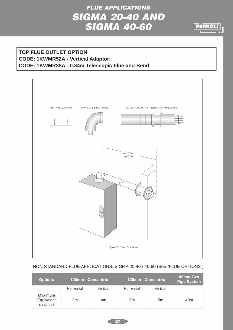
FLUE APPLICATIONS
SIGMA 20-40 AND SIGMA 40-60
TOP FLUE OUTLET OPTIONCODE: 1KWMR52A - Vertical Adaptor; CODE: 1KWMR38A - 0.84m Telescopic Flue and Bend
NON-STANDARD FLUE APPLICATIONS; SIGMA 20-40 / 40-60 (See “FLUE OPTIONS”)
100 / 60 CONCENTRIC TELESCOPIC FLUE (0.84m)100 / 60 M/F BEND - 90deg.VERTICAL ADAPTOR
max 0.84mmin 0.54m
Typical Top Flue - Side Outlet
Horizontal Vertical Horizontal Vertical
Options 100mm Concentric 125mm Concentric80mm Two
Pipe System
MaximumEquivalentdistance
3m 4m 5m 5m 40m

FLUE APPLICATIONS
SIGMA 60-100
28
STANDARD REAR FLUECODE: 823204 Includes: 1-0.75m Flue (non-telescopic)
& Flue Bend
Top Flue - Side Outlet
Rear Outlet Max. Length 1m
100 / 60 CONCENTRIC FLUE (NON-TELESCOPIC) (0.75m)
max 0.84mmin 0.54m
0.75m
Non-Standard
Boiler Adaptor
BACK PLATE
SEALS
NON-STANDARD FLUE APPLICATIONS; SIGMA (See “FLUE OPTIONS”)
Rear Flue Application
Maximum Flue Length
SIGMA 60-100
= 1m
REAR MOUNTING PLATE AND SEALSSUPPLIED IN BOILER CARTON

FLUE APPLICATIONS
SIGMA 60-100
29
TOP FLUE OPTIONCODE: 1KWMA07Y Includes: 1-Appliance bend
1-0.84m Telescopic flue
NON-STANDARD FLUE APPLICATIONS; SIGMA 60-100 (See “FLUE OPTIONS”)
max 0.84mmin 0.54m
max 0.84mmin 0.54m
Typical Top Flue - Rear Outlet Typical Top Flue - Side Outlet
100 / 60 CONCENTRIC TELESCOPIC FLUE (0.84m)100 / 60 APPLIANCE BEND - 90deg.
Horizontal Vertical Horizontal Vertical
Options 100mm Concentric 125mm Concentric80mm Two
Pipe System
MaximumEquivalentdistance
3m 4m 5m 5m 40m

FLUE APPLICATIONS
TEMPRA 12 / 18
30
STANDARD TOP FLUE KITCODE: 1KWMR38A Includes: 1-Flue Bend
1-0.84m Telescopic Flue
NON-STANDARD FLUE APPLICATIONS; TEMPRA 12 / 18 (See “FLUE OPTIONS”)
Typical Top Flue - Side Outlet
100 / 60 CONCENTRIC TELESCOPIC FLUE (0.84m)100 / 60 M/F BEND - 90deg.
max 0.84mmin 0.54m
Typical Top Flue - Rear Outlet
max 0.84mmin 0.54m
Horizontal Vertical Horizontal Vertical
Options 100mm Concentric 125mm Concentric80mm Two
Pipe System
MaximumEquivalentdistance
3m 4m 5m 5m 45m

FLUE APPLICATIONS
TEMPRA 12 / 18
31
REAR FLUE OPTIONCODE: 1KWMR04A Includes: 1-Back Plate; 2-SealsCODE: 823204 1-0.75m Non-Telescopic Flue
Rear Outlet Max. Length 1m N.B. No flue restictor required for rear outlet
100 / 60 CONCENTRIC FLUE (NON-TELESCOPIC) (0.75m)
0.75m
BACK PLATE
SEALS
NON-STANDARD FLUE APPLICATIONS; TEMPRA 12 / 18 (See “FLUE OPTIONS”)
Rear Flue Application
Maximum Flue Length
TEMPRA 12 / 18
= 1m

FLUE APPLICATIONS
TEMPRA 24
32
STANDARD TOP FLUE KITCODE: 1KWMA07Y Includes: 1-Appliance Bend;
1-0.84m telescopic flue
NON-STANDARD FLUE APPLICATIONS; TEMPRA 24 (See “FLUE OPTIONS”)
max 0.84mmin 0.54m
max 0.84mmin 0.54m
Typical Top Flue - Side OutletTypical Top Flue - Rear Outlet
100 / 60 CONCENTRIC TELESCOPIC FLUE (0.84m)100 / 60 APPLIANCE BEND - 90deg.
Horizontal Vertical Horizontal Vertical
Options 100mm Concentric 125mm Concentric80mm Two
Pipe System
MaximumEquivalentdistance
3m 4m 5m 5m 48m

FLUE APPLICATIONS
TEMPRA 24
33
REAR FLUE OPTIONCODE: 822181 Includes: 1-0.75m Non-Telescopic Flue
1-Fan Extension; 1-Back Plate; 2-Seals
Rear Outlet Max. Length 1m N.B. No flue restictor required for rear outlet
100 / 60 CONCENTRIC FLUE (NON-TELESCOPIC) (0.75m)
0.75m
BACK PLATE
FAN EXTENSION
SEALS
NON-STANDARD FLUE APPLICATIONS; TEMPRA 24 (See “FLUE OPTIONS”)
Rear Flue Application
Maximum Flue Length
TEMPRA 24
= 1m

FLUE APPLICATIONS
TEMPRA 30
34
STANDARD TOP FLUE KITCODE: 1KWMA07Y Includes: 1-Appliance Bend;
1-0.84m telescopic flue
NON-STANDARD FLUE APPLICATIONS; TEMPRA 30 (See “FLUE OPTIONS”)
max 0.84mmin 0.54m
max 0.84mmin 0.54m
Typical Top Flue - Side OutletTypical Top Flue - Rear Outlet
100 / 60 CONCENTRIC TELESCOPIC FLUE (0.84m)100 / 60 APPLIANCE BEND - 90deg.
Horizontal Vertical Horizontal Vertical
Options 100mm Concentric 125mm Concentric80mm Two
Pipe System
MaximumEquivalentdistance
3m 4m 5m 5m 50m

FLUE APPLICATIONS
TEMPRA 30
35
REAR FLUE OPTIONCODE: 822186 Includes: 1-0.75m Flue (non-telescopic)
1-Fan Extension; 1-Boiler Adaptor
Rear Outlet Max Length 1m N.B. No flue restictor required for rear outlet
100 / 60 CONCENTRIC FLUE (NON-TELESCOPIC) (0.75m)
0.75m
FAN EXTENSION
BOILER ADAPTOR
NON-STANDARD FLUE APPLICATIONS; TEMPRA 30 (See “FLUE OPTIONS”)
Rear Flue Application
Maximum Flue Length
TEMPRA 30
= 1m

FLUE APPLICATIONS
ARENA 30A & 30C
36
STANDARD TOP FLUE KITCODE: ARENA 30A - 822024 Both include: Valves; Screws; Boiler Adaptor;
ARENA 30C - 822025 0.75m Flue; 90deg. Bend
NON-STANDARD FLUE APPLICATIONS; ARENA 30A & 30C (See “FLUE OPTIONS”)
60 / 100 CONCENTRIC
100 / 60 CONCENTRIC FLUE (NON-TELESCOPIC) (0.75m)
100 / 60 M/F BEND - 90deg.
APPLIANCE ADAPTOR
Horizontal Vertical Horizontal Vertical
Options 100mm Concentric 125mm Concentric80mm Two
Pipe System
MaximumEquivalentdistance
11m 12m 20m 21m 100m
N.B. The Appliance Adaptor must be used for ALL CONCENTRIC FLUE Applications - Horizontal or Vertical

FLUE APPLICATIONS
MAXIMA 35C
37
STANDARD TOP FLUE KITCODE: TO FOLLOW Includes: 1-Appliance Bend;
1-0.993m Concentric Terminal
max 0.993mmin 0.54m
max 0.993mmin 0.54m
Typical Top Flue - Rear OutletTypical Top Flue - Side Outlet
100 / 60 CONCENTRIC TELESCOPIC FLUE (0.993m)100 / 60 APPLIANCE BEND - 90deg.
Horizontal Vertical Horizontal Vertical
Options 100mm Concentric 125mm Concentric80mm Two
Pipe System
MaximumEquivalentdistance
5m 6m TO FOLLOW TO FOLLOW 55m

FLUE APPLICATIONS
MAXIMA 27C, 27S, AND 35S
38
STANDARD FLUE KIT (TOP FLUE ONLY)CODE: Includes:
Horizontal Vertical Horizontal Vertical
Options 100mm Concentric 125mm Concentric80mm Two
Pipe System
MaximumEquivalentdistance
DETAILS
TO
FOLLOW

39
FLUE OPTIONS
HORIZONTAL AND VERTICALCONCENTRIC FLUES
To calculate the total resistance of the flue refer to the tables below:
TABLE 1:
RESISTANCE FACTORS
100mm Concentric Bend (90deg.)
100mm Concentric Bend (45deg.)
100mm Concentric Vertical Flue Terminal
125mm Concentric Bend (90deg.)
125mm Concentric Bend (45deg.)
125mm Concentric Vertical Flue Terminal
N.B. When calculating resistance factors for Horizontal ConcentricFlues, please note that the Appliance Bend and the Flue Terminalare already allowed for in the stated “Maximum Flue Length”.
From the above table it can be seen that a 100mm 90deg. bend is equivalent to 1m of straight pipeand a 125mm 90deg. bend is equivalent to 0.5mtr of straight pipe.
1.0m
0.5m
0m
0.5m
0.25m
0m
KWMR81U
KWMA64A
1KWMR19A
KWMA73K
KWMA72K
1KWMR12A
TABLE 2:
Horizontal Vertical Horizontal VerticalBOILER
100mm Concentric 125mm Concentric
3mMODENA 80/102 4m 5m 5m
3mDOMINA 80/102 * 4m 5m 5m
3mSIGMA * 4m 5m 5m
3mTEMPRA 12 / 18 * 4m 5m 5m
3mTEMPRA 24 / 30 * 4m 5m 5m
3mF24 & F30 * 4m 5m 5m
11mARENA 30A & 30C
* Rear flue max. length = 1m
12m 20m 21m
5mMAXIMA 35C 6m TO FOLLOW TO FOLLOW
MAXIMUM PERMISSIBLE FLUE LENGTH

FLUE OPTIONS
40
80MM TWO PIPEFLUEING SYSTEM
To calculate the total resistance of the flue refer to the tables below:
RESISTANCE FACTORS OF 80MM FLUE PIPE AND FITTINGS (HORIZONTAL)
Horizontal Flue Pipe
Horizontal Air Intake
90deg. Bend - Flue Gas
90deg. Bend - Air
45deg. Bend - Flue Gas
45deg. Bend - Air
Actual Length (x2)
Actual Length
2.5m
1.5m
2.2m
1.2m
Flue Gas Terminal (Horizontal) 5.0m
Air Terminal 2.0m
KWMA83A (1m Length)
KWMA83A (1m Length)
KWMA82A
KWMA82A
KWMA65A
KWMA65A
KWMA86A
KWMA85A
MAXIMUM EQUIVALENT FLUE LENGTH USING TOP OUTLET APPLICATION
MODENA 80/ DOMINA 80
SIGMA
TEMPRA 12 / 18
TEMPRA 24
TEMPRA 30
F24
48.0m
MODENA 102/ DOMINA 102 50.0m
40.0m
45.0m
48.0m
50.0m
48.0m
F30 50.0m
ARENA 30A & 30C 100.0m
MAXIMA 35C 55.0m
RESISTANCE FACTORS OF 80MM FLUE PIPE AND FITTINGS (VERTICAL)
Vertical Flue Pipe
Vertical Air Pipe
Vertical terminal
Condensate Outlet
Actual Length
Actual Length
3.0m
3.0m
KWMA83A
KWMA83A
1KWMR47A
1KWMA55U
N.B. Extensive runs of 80mm Flue Pipe should, wherever possible, be effectively insulated to avoidexcessive condensation. This is essential where the flue runs through exposed areas such as roofspaces etc.

FLUE OPTIONS
FLUE RESTRICTOR SIZES
41
100MM HORIZONTAL CONCENTRIC FLUES
MODEL
MODENA 80
MODENA 102
DOMINA 80
DOMINA 102
F24
F30
SIGMA 20-40
SIGMA 40-60
SIGMA 60-100
TEMPRA 12
TEMPRA 18
TEMPRA 24
TEMPRA 30
ARENA 30A & 30C
MAXIMA 35C
TOP OUTLET
<1m
>1m
<1m
>1m
<1m
>1m
<1m
>1m
<1m
>1m
<1m
>1m
<1m
>1m
<1m
>1m
<1m
between 1-2m
over 2m
<1m
>1m
<1m
>1m
<1m
>1m
<1m
>1m
No restrictor required
No restrictor required
RESTRICTOR
50mm
No restrictor
52mm
No restrictor
50mm
No restrictor
52mm
No restrictor
50mm
No restrictor
52mm
No restrictor
36mm
39mm
41mm
46mm
43mm
47mm
No restrictor
37mm
37mm
43mm
47mm
50mm
No restrictor
52mm
No restrictor
REAR OUTLET
n/a
n/a
max.1m
max.1m
max.1m
max.1m
max.1m
max.1m
max.1m
max.1m
max.1m
max.1m
max.1m
max.1m
RESTRICTOR
No restrictor
No restrictor
No restrictor
No restrictor
No restrictor
36mm
46mm
No restrictor
No restrictor
No restrictor
No restrictor
No restrictor

FLUE OPTIONS
FLUE RESTRICTOR SIZES
42
80MM TWO PIPE FLUE SYSTEM
MODEL TOTAL RESISTANCE RESTRICOR SIZE
MODENA 80
0 - 13m 45mm
13 - 23m 47mm
23 - 38m 50mm
38 - 48m No restrictor
MODENA 102
0 - 20m 47mm
20 - 35m 50mm
35 - 45m 52mm
45 - 50m No restrictor
F24
0 - 13m 45mm
13 - 23m 47mm
23 - 38m 50mm
38 - 48m No restrictor
F30
0 - 20m 47mm
20 - 35m 50mm
35 - 45m 52mm
45 - 50m No restrictor
SIGMA 20-40
0 - 20m 36mm
20 - 30m 39mm
30 - 40m 39mm
SIGMA 40-60
0 - 20m 41mm
20 - 30m 46mm
30 - 40m 46mm
SIGMA 60-100
0 - 4m 43mm
4 - 12m 45mm
12 - 25m 47mm
25 - 33m 50mm
33 - 40m No restrictor
TEMPRA 12 0 - 45m 37mm
TEMPRA 180 - 15m 43mm
15 - 45m 47mm
TEMPRA 24
0 - 10m 45mm
10 - 20m 47mm
20 - 35m 50mm
35 - 48m No restrictor
TEMPRA 30
0 - 20m 47mm
20 - 35m 50mm
35 - 45m 52mm
45 - 50m No restrictor

A
B90 degree bend
a
b
c
d
43
FLUE OPTIONS
HORIZONTAL CONCENTRICFLUES
bendsA 45 degree
BC
a
b
c
d
Max. Equivalent Flue Length
Modena, Domina, Sigma,Tempra, F24, F30,
Arena 30A, Arena 30C 20m11m
Maxima 35C To Follow5m
5m3m
125mm100mm
Ref. Description Code
a Appliance bend 1KWMA31Y
b Flue pipe 1KWMA56U
c Horizontal terminal 823204
d 90 deg. bend 1KWMR81U
Example Flue Length Total
100mm Concentric Flue
Example: F30(100mm Concentric Flue)
A B
1m 0.75m100mm Flue 1.75m
Total 2.75m
90 deg. bend (1 x) 1m 1m
Refer to Tables 1& 2 for resistance values of flue fittings and maximum allowed flue length
N.B. No restrictor required for flue lengths above 1m
Example Flue Length Total
125mm Concentric Flue
A B
2m 1m
C
0.9m125mm Flue 3.9m
Total 4.9m
45 deg. bend (2 x) 0.5m 1m
N.B. No restrictor required for flue lengths above 1m
Ref. Description Code
a Appliance bend 823017
b Flue pipe 1KWMR56U
c 45 degree bend 1KWMA72K
d Horizontal terminal 1KWMR56A
Example: F30(125mm Concentric Flue)

44
FLUE OPTIONS
HORIZONTAL CONCENTRICFLUES
c
A
B
C
90 degree bend
Appliance bend
b
c
da
b
a
B
A
90 degree bend
b
c d
Refer to Tables 1& 2 for resistance values of flue fittings and maximum allowed flue length
Example Flue Length Total
100mm Concentric Flue
A B
1m 0.75m100mm Flue 1.75m
Total 2.75m
90 deg. bend (1 x) 1m 1m
N.B. No restrictor required for flue lengths above 1m
Example Flue Length Total
125mm Concentric Flue
A B
1m 1m
C
1.9m125mm Flue 3.9m
Total 4.9m
90 deg. bend (2 x) 0.5m 1m
N.B. No restrictor required for flue lengths above 1m
Ref. Description Code
a Vertical adaptor 1KWMA33K
b Flue pipe 1KWMA56U
c 90 degree bend 1KWMR81U
d Horizontal terminal 823204
Example: F24(100mm Concentric Flue)
Ref. Description Code
a Appliance bend 823017
b Flue pipe 1KWMR56U
c 90 degree bend 1KWMA73K
d Horizontal terminal 1KWMR56A
Example: Modena 102(125mm Concentric Flue)
Max. Equivalent Flue Length
Modena, Domina, Sigma,Tempra, F24, F30,
Arena 30A, Arena 30C 20m11m
Maxima 35C To Follow5m
5m3m
125mm100mm

45
FLUE OPTIONS
VERTICAL CONCENTRIC FLUEAPPLICATIONS
Height
a
b
c
d
Height
H3
H1
H2
45 degree bends
a
b
c
d
e
Example 1: 100mm Concentric Flue
Max. allowed height = 4m
Actual height of flue withno bends can total a max.of ..........
Total
4m
Example 2: 125mm Concentric Flue
Max. allowed height = 5m
Maximum equivalent flue height for ConcentricVertical Flue = H1 + H2 + H3 + (2 x 45 deg.bends)
125mm
EH = H 1
1m
H 2
1m
H 3
2m
45 deg.bends (x2)
0.25m(x2)
Total
= 4.5m
Ref. Description Code
a Vertical adaptor 1KWMA33K
b Flue pipe 1KWMA56U
c Roof terminal 1KWMA83U
dRoof slate
(Pitched roof) 1KWMA82U
Example: Tempra 24(100 mm Concentric Flue) Ref. Description Code
a Vertical adaptor 1KWMA71K
b Flue pipe 1KWMR56U
c 45 degree bend 1KWMA72K
d Roof terminal 1KWMR83A
Example: Tempra 24(125mm Concentric Flue)
eRoof slate
(Pitched roof) 1KWMA82U
46
FLUE OPTIONS
80MM TWO PIPESYSTEM (HORIZONTAL)
L1 (V)
L1 (H)
D1 (H)
L2 (H)
D2 (H)
L3 (H)
D3 (H)
150mm
a
b
bc
b
e
d
150mm
D1 (V)
D2 (H)
D2 (V)D1 (H)
150mm
a
b
c
e
d
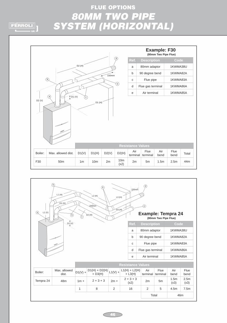
D1 (V)
Resistance Values
Boiler:
F30
Total
44m
Max. allowed dist.
50m
D1(V)
1m
D1(H)
10m
D2(V)
2m
D2(H)
10m(x2)
Air terminal
Flue terminal
Air bend
Fluebend
2m 5m 1.5m 2.5m
Resistance Values
Boiler:
Tempra 24
Max. alloweddist.
48m
L1(V) +
2m +
D1(V) +
1m + 2 + 3 + 3
L1(H) + L2(H)+ L3(H)
2 + 3 + 3(x2)
D1(H) + D2(H)+ D3(H)
Air terminal
Flue terminal
Air bend
Fluebend
2m 5m1.5m(x3)
2.5m(x3)
2 161 8 2 5 4.5m
Total 46m
7.5m
Ref. Description Code
a 80mm adaptor 1KWMA38U
b 90 degree bend 1KWMA82A
c Flue pipe 1KWMA83A
d Flue gas terminal 1KWMA86A
Example: F30(80mm Two Pipe Flue)
e Air terminal 1KWMA85A
Ref. Description Code
a 80mm adaptor 1KWMA38U
b 90 degree bend 1KWMA82A
c Flue pipe 1KWMA83A
d Flue gas terminal 1KWMA86A
Example: Tempra 24(80mm Two Pipe Flue)
e Air terminal 1KWMA85A

47
FLUE OPTIONS
80MM TWO PIPESYSTEM (HORIZONTAL)
L1(V)
L1(H)L2(H)
D2(H)
L3(H)
D3(H)
D1(H)D1(V)150mma
b
c
d
e
f
D2(H)
D1(H)
D2(V)
D1(V)
a
b
c
c
e
d
Resistance Values
Boiler:
F24
Total
32m
Max. allowed dist.
48m
D1(V) +
1m
D1(H) +
15m
D2(V) +
1m
D2(H)
2m(x2)
Air terminal
Flue terminal
Air bend
Fluebend
2m 5m 1.5m 2.5m
Ref. Description Code
a 80mm adaptor 1KWMA38U
b 90 degree bend 1KWMA82A
c Flue pipe 1KWMA83A
d Flue gas terminal 1KWMA86A
Example: F24(80mm Two Pipe Flue)
e Air terminal 1KWMA85A
Ref. Description Code
a 80mm adaptor 1KWMA38U
b 80mm pipe 1KWMA82A
c 90 degree bend 1KWMA83A
d 45 degree bend 1KWMA65A
Example: Tempra 30(80mm Two Pipe Flue)
e Flue gas terminal 1KWMA86A
f HorizontalAir terminal 1KWMA85A
Component Total Resistance
Pipe flue gasL1(V) + L1(H) + L2(H) + L3(H)
e.g. 1m + 3m + 0.5m + 2m
N.B. horizontal flue pipe actuallenght x 2
1 + (3 + 0.5 + 2 x 2)
Pipe airD1(V) + D1(H) + D2(H) + D3(H)e.g. 0.5m + 3m + 0.5m + 1m
90 degree bends 1 - Flue gas1 - Air
45 degree bends
Flue gas terminalAir terminal
2 - Flue gas2 - Air
2.51.52.2 (x 2) = 4.41.2 (x 2) = 2.4
1
1
=
= 0.5 + 3 + 0.5 + 1
=
=
===
12m
5m
4m
6.8m
34.8m2m
5m=
Total Resistance

bends
H2
45 degree bends
H1
90 degree
Air Wall Terminal
L2
H3
L1
a
b
c
d
e
f
48
FLUE OPTIONS
80MM TWO PIPEVERTICAL FLUE
Flue Gas
Max. total flue length = 50m
80mm Vertical Flue Outlet/Wall Air Inlet
45 deg. bends
Sub Total
Vertical Flue Terminal
(H1 + H2 + H3)eg 2 + 3 + 5 = 10
Vertical Flue Pipe
Resistances
2.2m (x2) = 4.4m
17.4m
3m
10m
Air Inlet
90 deg. bends
Sub Total
Air Wall Terminal
(L1 + L2)eg 2 + 15 = 17
Horizontal Air Pipe
Resistances
1.5 (x2) = 3m
22m
2m
17m
Total
7.4m
39.4m
5m
27m
Ref. Description Code
a 80mm adaptor 1KWMA38U
b 45 degree bends 1KWMA65A
c 90 degree bends 1KWMA82A
d 80mm pipe 1KWMA83A
Example: F30(80mm Two Pipe Flue)
e80mm vertical
terminal1KWMR47A
f Horizontal airterminal
1KWMA85A

49
FLUE OPTIONS
80MM TWO PIPEVERTICAL FLUE
with Terminal
Pipe
Height
a
H
Vertical Flue Outlet
Flue Gas
Air Pipeb
c
d
Resistance - Flue
80mm Vertical Flue Outlet
Vertical Flue Outlet with Terminal
Height = H (eg 8m)
Total
Resistance - Air
Height = H (eg 8m)
Total
12m12m
16m
28m
Max. Equivalent Flue Height
Modena 80 48m
Ref. Description Code
a 80mm adaptor 1KWMA38U
b 80mm pipe 1KWMA83A
c 80mm roof terminal 1KWMA84U
d Vertical roof slate 1KWMA82U
Example: Modena 80(80mm Two Pipe Flue)

FLUE OPTIONS
S.E. DUCT / ‘U’ DUCT
50
FLUE AIR
FLUE AIR
FLUE AIR
FLUEAIR AIR
AIR
FLUE AIR
REFER TO B.S. 5440 - 1:2000 FOR FURTHER INFORMATION

51
FLUE TERMINAL POSITIONS
AG
B
C
D, E
Q
P
I
F
J L
Q
N
M
M
N
K
H
H
Q
N.B. SEE OVER FOR MINIMUM DIMENSIONS OF FLUE TERMINAL POSITIONS

52
MINIMUM DIMENSIONS OFFLUE TERMINAL POSITIONS
(ALL TYPES)
NOTE
N/A = Not applicable
a In addition, the terminal should not be nearer than 150mm (fanned draught) or300mm (natural draught) to an opening in the building fabric formed for the purposeof accommodating a built-in element such as a window frame. Seperation distancesare linked to the rated heat inputs as shown.
Condensing Terminal Positions: If the flue is to be terminated at low level, then thepotential effect of the plume must be considered.
The plume should not be directed:
DIMENSION TERMINAL POSITION(kW input expressed in net)
BALANCED FLUESROOM SEALED
FANNED DRAUGHT
Aa Directly below an opening, air brick,300mm
opening windows, etc.
Ba Above an opening, air brick,300mm
opening windows, etc.
Ca Horizontally to an opening, air brick,300mm
opening windows, etc.
D Below gutters, soil pipes or drain pipes 75mm
E Below eaves 200mm
F Below balconies or car port roof 200mm
G From a vertical drain pipe or soil pipe 150mm
H From an internal or external corner 100mm
I Above ground roof or balcony level 300mm
J From a surface facing the terminal 600mm
K From a terminal facing the terminal 1200mm
LFrom an opening in the car port (e.g. door,window) into the dwelling
1200mm
M Vertically from a terminal on the same wall 1500mm
N Horizontally from a terminal on the same wall 300mm
O From the wall on which the terminal is mounted N/A
P From a vertical structure on the roof 150mm
Q Above intersection with roof 300mm
across a frequently used access route
towards a window or door
across a neighbouring property

1000 50
Ø62
Ø10
0
Ø60
Ø10
0
500 50
ø 8
2ø
127
ø 8
0ø
125
900
80125
100050
ø 8
2ø
127
ø 8
0ø
125
Ø10
2
1
Ø10
0
max. 840
58min. 540
Ø60
2
Ø66
11480
Ø62
Ø118
95
Ø80
Ø10
2
Ø66
11480
Ø62
Ø126.5
95
Ø80
53
FLUE OPTIONS
ACCESSORIES FOR STANDARD BOILERS
CODE DRAWING PHOTO DESCRIPTION
1KWMA56U Concentric extension(M-F)Ø 60/100 length 1 m
1KWMR56U Concentric extension(M-F)Ø 80/125 length 1 m
1KWMA07Y
F24/F30, Modena,Sigma 60/100 andTempra 24/30
Inlet/outlet horizontal concentric kitØ 60/100 (telescopic)Concentric flanged bend 900
Ø 60/100
1KWMA31Y
For F24/F30, Modena,Sigma 60/100 andTempra 24/30
Concentric flangedbend 900
Ø 60/100
1KWMR56A
1KWMR41A Concentric extension(M-F)Ø 80/125 length 0,5 m
Inlet/outlet concentricterminalØ 80/125 length 0,9 m

54
FLUE OPTIONS
ACCESSORIES FOR STANDARD BOILERS
ø60ø100
ø62
ø10250
45∞
315
555
119
52.4
39
ø60ø100
ø10
2ø
62
115
50
115
1
Ø10
0
Max. 840
58Min. 540
Ø60
2
ø80ø125
ø82
ø12750
45∞
307,
5
71,5
5
122
30
ø80ø125
ø12
7ø
82
110
40,5
110
ø60ø100
ø10
2ø
62
115
50
115
ø 136
141
513
6
ø1385
CODE DRAWING PHOTO DESCRIPTION
1KWMA64A Concentric bend 450
(M-F)Ø 60/100
Resistance factor 0,5 m
1KWMR38A
For Sigma 20/40,Sigma 40/60and Tempra 12/18
Inlet/outlet horizontal concentric kitØ 60/100 (telescopic)Concentric bend 900
(M-F) Ø 60/100Boiler adaptor requiredfor Sigma (1KWMR52A)
1KWMA72K Concentric bend 450
(M-F)Ø 80/125
Resistance factor 0,25 m
1KWMA73K Concentric bend 900
(M-F)Ø 80/125
Resistance factor 0,5 m
1KWMR81U
For Sigma 20/40,Sigma 40/60and Tempra 12/18
Concentric bend 900
(M-F)Ø 60/100
Resistance factor 1,0 m
1KWMA71K
For Modena andSigma 60/100
Vertical flangedconnection withcondensate outletØ 80/125

55
FLUE OPTIONS
ACCESSORIES FOR STANDARD BOILERS
100
60
142,5
170
50
82127
ø82
5013
5
50
ø8250
ø80
55
45∞
50.612
2
ø80
100050
ø82
ø80
50050
ø82
ø80
50
ø82
110
110
ø330
22
110
ø132.5
CODE DRAWING PHOTO DESCRIPTION
1KWMR07A Concentric adaptor(M-F)from Ø 60/100 to Ø80/125
1KWMA55U Vertical pipe withcondensate outletØ 80
Bend 450 (M-F)Ø 80
Resistance factorFlue Gas 2,2 mAir 1,2 m
1KWMA83A Extension (M-F)Ø 80 length 1 m
1KWMA38A Extension (M-F)Ø 80 length 0,5 m
1KWMA82A
1KWMA65A
Bend 900 (M-F)Ø 80
Resistance factorFlue Gas 2,5 mAir 1,5 m
1KWMA81U Roof tile for flat roofsBlack PVC

56
FLUE OPTIONS
ACCESSORIES FOR STANDARD BOILERS
3519
5
500
41∞
23∞
30∞
12∞
500
1195
6
ø60ø100
1295
ø80 ø80
6
ø100.5
68
ø138ø126,5
ø100.5ø62
ø80
102.
56810
1
ø138ø126,5
175
200
CODE DRAWING PHOTO DESCRIPTION
1KWMA33K
For F24/F30, Modena,Sigma 60/100 andTempra 24/30
Vertical flangedconcentric connectionØ 60/100
1KWMA82U Roof tile for slopingroofsBlack PVC andlead slate
1KWMA83U Concentric outlet flueinlet airØ 60/100
Resistance factor 1,2 m
1KWMA84U Outlet flue inlet air withtwin connectionØ 80/80
Resistance factor 12,0 m
1KWMR52A
For Sigma 20/40,Sigma 40/60 andTempra 12/18
Vertical flangedconcentric connectionØ 60/100
1KWMR12A Terminal forconcentric pipeØ 80/125
Resistance factor NIL

57
FLUE OPTIONS
ACCESSORIES FOR STANDARD BOILERS
175
200
160
9016
0
Ø80
1145
6
ø82
ø138
7 5
ø126,5ø104
ø14
6
ø72 ø78
15
ø80
.5
12
CODE DRAWING PHOTO DESCRIPTION
1KWMR19A Terminal forconcentric pipeØ 60/100
Resistance factor NIL
1KWMR47A Terminal for pipeØ 80
Resistance factor 3,0 m
1KWMR83A Concentric inlet/outletstandard roof terminalØ 80/125
Resistance factor 1,2 m
1KWMA38U Blanking flange for twinpipe systemsØ 80/80
1KWMA84A External wall gasketØ 80PVC
1KWMA85A Air wall terminalØ 80Stainless steel
Resistance factor 2,0 m

58
FLUE OPTIONS
ACCESSORIES FOR STANDARD BOILERS
70
ø80
.5
80
60100
165
80
ø22
0ø
118
33
ø12
5
ø16
7ø
93
20
ø10
0
Ø100
Ø80
CODE DRAWING PHOTO DESCRIPTION
1KWMA86A Flue wall terminalØ 80Stainless steel
Resistance factor 5,0 m
1KWMA90U
Sigma 20/40, 40/60and Tempra 12/18
“T” diverterfrom concentric Ø 60/100to twin Ø 80/80
Resistance factor NIL
1KWMR09A Internal/external wall gasket for pipesØ 125
1KWMR11A Internal/external wall gasketØ 100
1KWMR46A Pipe wall fixing collarØ 100Steel
1KWMR48A Pipe wall fixing collarØ 80Steel

59
FLUE OPTIONS
ACCESSORIES FOR STANDARD BOILERS
Ø125
CODE DRAWING PHOTO DESCRIPTION
1KWMR49A Pipe wall fixing collarØ 125Steel

FLUE OPTIONS
ACCESSORIES FOR CONDENSING BOILERS
60
1000
124
900
80125
ø60ø100
ø10
2ø
62
115
50
115
ø60ø100
ø62
ø10250
45∞
315
55
5
119
52.4
39
ø80ø125
ø82
ø12750
45∞
307,
5
71,5
5
122
30
ø80ø125
ø12
7ø
82
110
40,5
110
CODE DRAWING PHOTO DESCRIPTION
1KWMA56W
For all condensingboilers
Concentric inlet/outletterminal anti-rainØ 60/100 length 1 m
1KWMA58W
For all condensingboilers
Concentric inlet/outletterminalØ 80/125 length 0,9 m
1KWMA35W
For all condensingboilers
Concentric bend 900
(M-F)Ø 60/100
Resistance factor 1,0 m
1KWMA64W
For all condensingboilers
Concentric bend 450
(M-F)Ø 60/100
Resistance factor 0,5 m
1KWMA72W
For all condensingboilers
Concentric bend 450
(M-F)Ø 80/125
Resistance factor 0,25 m
1KWMA73W
For all condensingboilers
Concentric bend 900
(M-F)Ø 80/125
Resistance factor 0,5 m

FLUE OPTIONS
ACCESSORIES FOR CONDENSING BOILERS
61
120Ø60 Ø60
Ø60
Ø100
120
223
ø60
134
ø82
5050
CODE DRAWING PHOTO DESCRIPTION
Ø10
0.5
Ø60
.8
10980
Ø118
95
Ø79
Ø96
Ø10
0.5
Ø60
.8
109
993
100 60
80
Ø118
95
Ø79
Ø96
ø100.5ø61
ø79.5
107
77
ø126.4
ø81.5
5014
5
67
1KWMA68W
For Maxima boilers
Concentric flangedbend 900
Ø 60/100(Complete with flue gassampling test point)
1KWMR53A
For Maxima boilers
Inlet/outlet horizontal concentric kitØ 60/100(Complete with flue gassampling test point)Concentric flanged bend900
1KWMA71W
For Maxima boilers
Vertical flangedconcentric connectionØ 60/100(Complete with flue gassampling test point)
1KWMR54A
For Maxima boilers
Condensing vertical flue 2pipe adaptor Ø 80(Complete with flue gassampling test point)Kit consists of 2 adaptors:1 x Flue1 x Air1 x Air blanking flange
1KWMA55Y
For Arena boilers
Adaptor from twinØ 60/60to concentric Ø 60/100White PPs
1KWMA02W
For Arena boilers
Reduction (M-F)Ø 60/80 length 134 mmWhite PPs2 required:1 x Flue1 x Air

NOTES

NOTES

NOTES

