flue gas recirculation for nox reduction · flue gas recirculation for nox reduction 2. nitrogen...
TRANSCRIPT

FLUE GAS RECIRCULATIONFOR NOX REDUCTION
FGRFlue Gas Recirculation
MAXIMUM COMFORT
FLUE GAS RECIRCULATION
FOR NOX REDUCTION
2
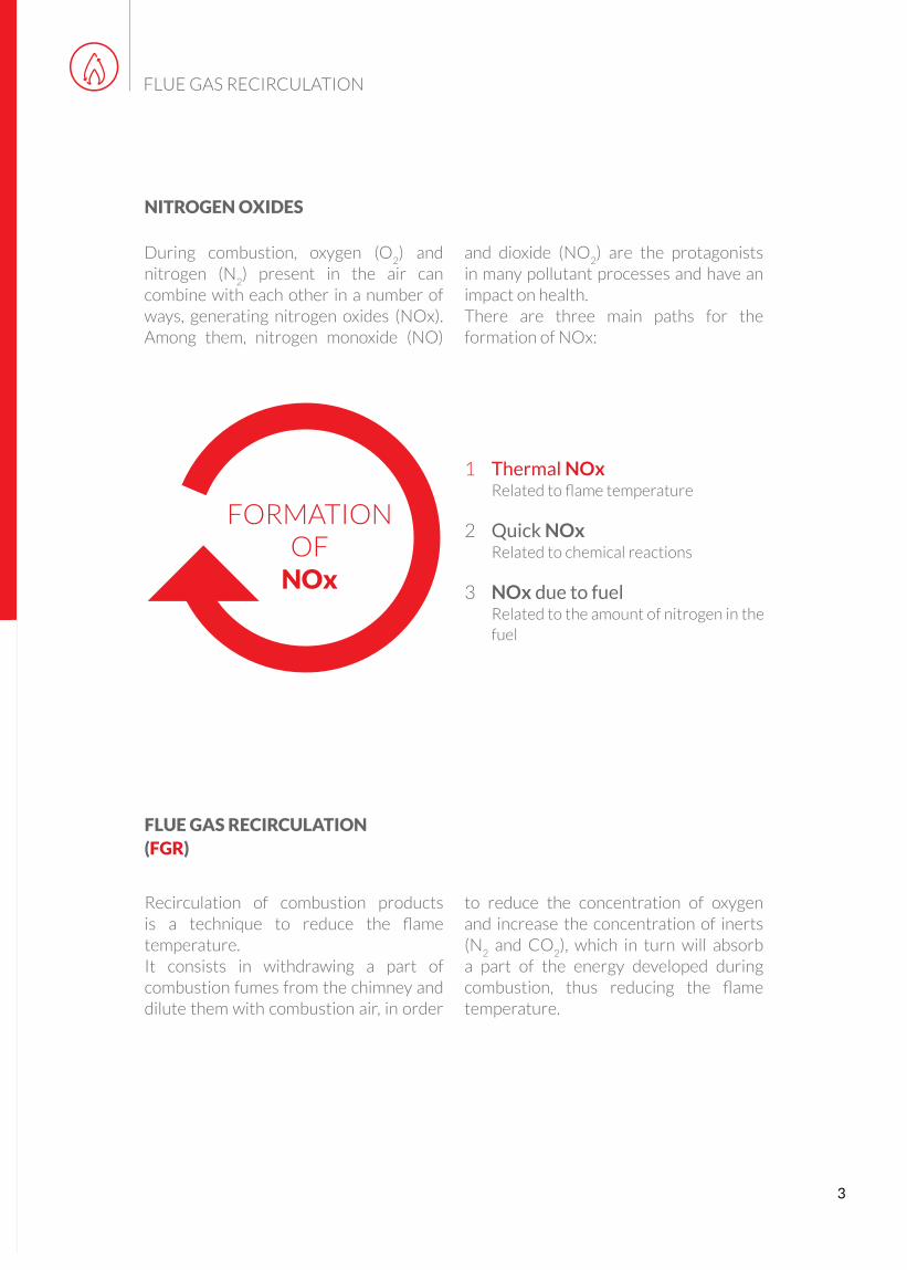
NITROGEN OXIDES
and dioxide (NO2) are the protagonists
in many pollutant processes and have an impact on health.There are three main paths for the formation of NOx:
During combustion, oxygen (O2) and
nitrogen (N2) present in the air can
combine with each other in a number of ways, generating nitrogen oxides (NOx). Among them, nitrogen monoxide (NO)
FLUE GAS RECIRCULATION
3
FLUE GAS RECIRCULATION (FGR)
to reduce the concentration of oxygen and increase the concentration of inerts (N
2 and CO
2), which in turn will absorb
a part of the energy developed during combustion, thus reducing the flame temperature.
Recirculation of combustion products is a technique to reduce the flame temperature. It consists in withdrawing a part of combustion fumes from the chimney and dilute them with combustion air, in order
FORMATION OF
NOx
1 Thermal NOx Related to flame temperature
2 Quick NOx Related to chemical reactions
3 NOx due to fuel Related to the amount of nitrogen in the fuel

FGR APPLICATION
Fume recirculation system is successfully used in all hot water, overheated boilers and in steam generators.
REDUCTION OF NOx
The effect obtained with this method for the reduction of NOx, considering natural gas as fuel, is significant and is a function of:- % of recirculated fumes- type of burner used- type of boiler
FLUE GAS RECIRCULATION
0
10
20
30
40
50
60
70
80
0 2,5 5 7,5 10 12,5 15 17,5 20 22,5
% R
idu
zio
ne
NO
x
% Fumi ricircolata
Riduzione degli NOx in funzione della % fumi ricircolata
4

5
FLUE GAS RECIRCULATION
FGR FOR MONOBLOC BURNERS
For monobloc burners, the simplest method uses the burner fan to withdraw fumes from the chimney and mix them with combustion air. The fume fl ow rate adjustment is performed by using a servo-controlled throttle valve, managed by the electronic equipment of the burner.
This method allows to reduce the operating range of the burner, since the following occurs:• a reduction of the amount of oxygen, at
equal volume fl ow rate;• an increase of combustion air
temperature;• a pressure drop due to the head losses
in the recirculation ducts.
1 Gas inlet.2 Condensate drainage valve.3 Burner.
4 Fume damper with servomotor.5 Duct for fume recirculation.6 Chimney.
Diagram 1 - External gas recirculation for monobloc burners.

FLUE GAS RECIRCULATION
FGR FOR DUAL BLOCK BURNERS
Several plant solutions can be used for separated burners. By keeping the original burner structure, it is possible to obtain:
I) External recirculation on the main fan intake with adjustment of fume fl ow rate through a damper positioned on the recirculation duct (Diagrams in Fig. 2 and 3).
II) External recirculation through an auxiliary fan with fume release downstream of the main fan and adjustment of fume fl ow rate through the damper, or through an inverter installed on the auxiliary fan (Fig. 4).
It is also possible to design the burner combustion head so that fumes are directly released in the combustion chamber. In this case there is:
III) External recirculation through an auxiliary fan with fume release on the burner sleeve and adjustment of fume fl ow rate through the damper, or through an inverter installed on the auxiliary fan (Fig. 5).
1 Gas inlet.2 Drainage valve.3 Burner.4 Fume damper with servomotor.5 Duct for fume recirculation.
6 Chimney.7 Main fan intake opening.8 Main fan.9 Fume recirculation fan.
Fig. 2 - External gas recirculation for separated burners. Fume release in the fan intake opening.
6

7
FLUE GAS RECIRCULATION
1 Gas inlet.2 Drainage valve.3 Burner.4 Fume damper with servomotor.5 Duct for fume recirculation.
6 Chimney.7 Main fan intake opening.8 Fan.9 Main fan adjustment servomotor.
Fig. 3 - External gas recirculation for separated burners. Fume release in the fan intake opening.
Fig. 4 - External gas recirculation for separated burners. Fume release downstream of the main fan delivery.
1 Gas inlet.2 Drainage valve.3 Burner.4 Fume damper with servomotor.5 Duct for fume recirculation.
6 Chimney.7 Main fan intake opening.8 Main fan.9 Fume recirculation fan.

FLUE GAS RECIRCULATION
Fig. 5 - External gas recirculation for separated burners. Fume release on burner sleeve.
1 Gas inlet.2 Drainage valve.3 Burner.4 Fume damper with servomotor.5 Duct for fume recirculation.
6 Chimney.7 Main fan intake opening.8 Main fan.9 Fume recirculation fan.
8

9
FLUE GAS RECIRCULATION
MONOBLOC BURNER WITH FGR ARRANGEMENT.(Fig. 1)
SEPARATED BURNER TO BE USED WITH DILUTION METHOD.(Fig. 2 - Fig. 3 - Fig. 4)
SEPARATED BURNER TO BE USED WITH METHOD OF FUME RELEASE ON SLEEVE.(Fig. 5)

How much recirculation?There is not a default value, generally it depends on the type of application and the required NOx emission values.
The assessment of the fume flow rate to be recirculated is performed by the Application Engineering technical department according to the information on the application, such as:
- NOx values [mg/Nm3] to reach;
- Type of boiler;- Thermal output at furnace;- Fuel type;- Pmax/Pmin modulation range;- Type of boiler operating fluid (hot, overheated water, steam, diathermic oil, etc.);- Fume temperature at chimney;- Chimney diameter;- Estimated (or current) % of O
2 in fumes;
- System layout.
FLUE GAS RECIRCULATION
10

CONCLUSIONS
The flue gas recirculation system (FGR) is a technique to reduce NOx emissions which is increasingly spreading thanks to the growing attention to environmental issues.
Today it represents the best compromise between costs and benefits, with a performance in terms of NOx reduction that is hard to reach with traditional burners. The cost of FGR system implementation is relatively low if compared with the other methods for NOx reduction, and such system can be installed on existing plants.
With regard to the above, it is always recommended to contact the burner manufacturer for sizing and for the choice of fume recirculation system components.
11
FLUE GAS RECIRCULATION
RESPECT FOR THE ENVIRONMENT
CONSUMPTION REDUCTION

www.baltur.com
Baltur S.p.A.Via Ferrarese, 10 - 44042 Cento (FE) - Italy
Tel. +39 051 684.37.11 - Fax +39 051 685.75.27/[email protected]
Data contained in this brochure shall be considered as indicative and not binding;Baltur reserves the right to change them without previous notice.
Co
de
00
01
00
11
65
- R
ev. 0
- V
er. 0
2/2
01
7