flue gas analyser
TRANSCRIPT

7/30/2019 Flue Gas Analyser
http://slidepdf.com/reader/full/flue-gas-analyser 1/32
FLUE GAS ANALYZERS AND
AMBIENT AIR ANALYZERS

7/30/2019 Flue Gas Analyser
http://slidepdf.com/reader/full/flue-gas-analyser 2/32
USE OF ANALYZERS IN POWER
PLANTAnalysers are used in power plant for
optimisation of fuel firing and monitoring
the environment.
7/30/2019 Flue Gas Analyser
http://slidepdf.com/reader/full/flue-gas-analyser 3/32
TYPES OF ANALYZERS
IN-SITU ANALYSERS (CROSS DUCT
ANALYZERS)
EXTRACTIVE ANALYZERS

7/30/2019 Flue Gas Analyser
http://slidepdf.com/reader/full/flue-gas-analyser 4/32
ANALYZERS USED AT NTPC-RIHAND
•OXYGEN ANALYZERS
•OPACITY ANALYZERS (SMOKE DENSITY)
•CO ANALYZERS
• NOX ANALYZERS
•SOX ANALYZERS
•CO2 ANALYZERS
•AMBIENY AIR ANALYZERS (SOX,NOX,CO2 AND SPM)

7/30/2019 Flue Gas Analyser
http://slidepdf.com/reader/full/flue-gas-analyser 5/32
OXYGEN ANALYZERS
•Oxygen analysers are used to monitor the optimum air flow toboiler.
•Excess air is provided to boiler to reduce the unburnt particles
and to provide air in case coal quantity demand increased rapidly.
•Oxygen analysers are also used to detect the leakages in flue gas
ducts.

7/30/2019 Flue Gas Analyser
http://slidepdf.com/reader/full/flue-gas-analyser 6/32
OXYGEN ANALYZERS
Installed location :
1. Flue gas economiser outlet
2. Flue gas outlet of APH (air pre heaters)
3. ID fans inlet
4. First pass of boiler at 65 meters

7/30/2019 Flue Gas Analyser
http://slidepdf.com/reader/full/flue-gas-analyser 7/32
OXYGEN ANALYZERS
Principle: The Zirconia sensor works on the principle of NernstThe sensor works on ionic conductivity of the Oxygen ions (movement
of oxygen ions through the Zirconia) which produces a potential across
the Zirconia cell, based on the difference of partial pressure of the
oxygen across the Zirconia cell .
The formation of ions, and its movement across the Zirconia requires
that the temperature of the Zirconia is raised to above 600ºC. This is
achieved by either keeping the sensor at temperature above 600ºC, or by
heating the Zirconia cell.

7/30/2019 Flue Gas Analyser
http://slidepdf.com/reader/full/flue-gas-analyser 8/32
OXYGEN ANALYZERS
The potential generated follows the Nernst Equation given below,
• which is used for calculating the oxygen percent from measured
values.
• E = 0.0215 * T * Ln(Pr/Px)
• where,
• E = Zirconia Cell voltage in millivolts
• T = Thermocouple temperature in Kelvin
• Pr = reference partial pressure
• Px is the unknown process oxygen in percent• 0.0215 is the cell constant
• 20.9 is the partial pressure of the oxygen of dry atmospheric air

7/30/2019 Flue Gas Analyser
http://slidepdf.com/reader/full/flue-gas-analyser 9/32
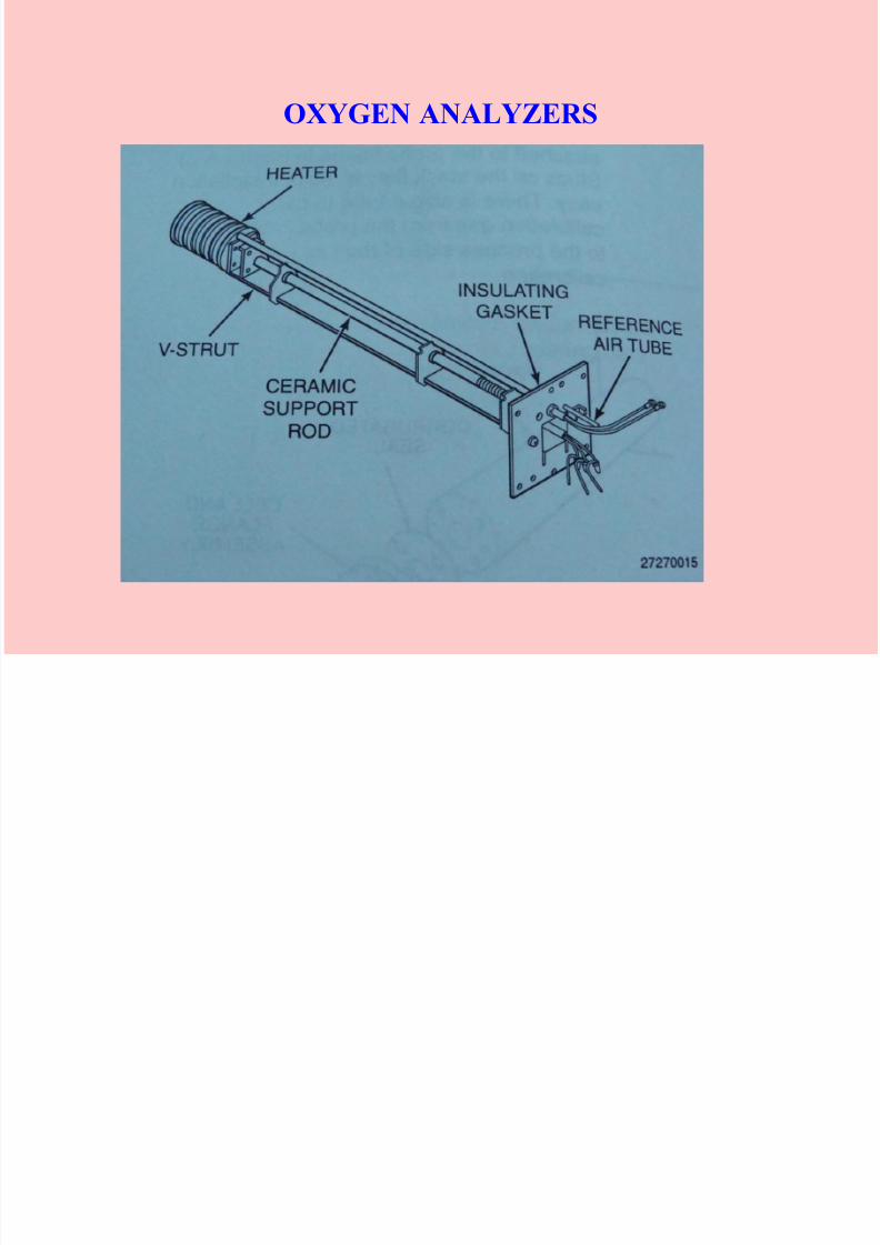
OXYGEN ANALYZERS
• Construction and installation
7/30/2019 Flue Gas Analyser
http://slidepdf.com/reader/full/flue-gas-analyser 10/32
OXYGEN ANALYZERS

7/30/2019 Flue Gas Analyser
http://slidepdf.com/reader/full/flue-gas-analyser 11/32
OXYGEN ANALYZERS
Maintenance
• ROUTINE CALIBRATION
• TIMELY REPLACEMENT OF ZIRCONIA SENSOR
• NO LEAKAGES AT PROBE
• REFERENCE AIR FLOW AND PRESSURE TO BE MAINTAINED
• FILTER TO BE ROUTINELY CLEANED OR REPLACED

7/30/2019 Flue Gas Analyser
http://slidepdf.com/reader/full/flue-gas-analyser 12/32
OPACITY ANALYZERS
• Opacity Analyzers are used to monitor the quantity of flue gases
discharge from boiler.
• These Analyzers provide an opportunity to measure the effectivenessof ESP(ELECTRO STATIC PRECIPITATOR)

7/30/2019 Flue Gas Analyser
http://slidepdf.com/reader/full/flue-gas-analyser 13/32
OPACITY ANALYZERS
Installed location :
1. ESP outlet
2. chimney

7/30/2019 Flue Gas Analyser
http://slidepdf.com/reader/full/flue-gas-analyser 14/32
OPACITY ANALYZERS
PRINCIPLE: When a beam of light crosses a medium containing
smoke or dust particles, some of the light is transmitted and some is
lost due to scattering. The fraction which is transmitted is called the
transmittance and the fraction which is lost is the opacity.
Transmittance = I / Io *100 %
I= intensity of light recieved
Io= intensity of light emitted
Hence opacity = 1-transmittance =(1- I/Io) *100%

7/30/2019 Flue Gas Analyser
http://slidepdf.com/reader/full/flue-gas-analyser 15/32
OPACITY ANALYZERS
LAMBERT-BEER LAW : The law describes the correlation between the attenuated
light intensity(I) and dust concentration (c) on the measuring path (x)
-c*x*k I =Io *e
I= intensity of the light received
Io=intensity of the light emitted
K =extinction coefficientC =dust concentration
X = path length

7/30/2019 Flue Gas Analyser
http://slidepdf.com/reader/full/flue-gas-analyser 16/32
OPACITY ANALYZERS
• Construction and installation

7/30/2019 Flue Gas Analyser
http://slidepdf.com/reader/full/flue-gas-analyser 17/32
OPACITY ANALYZERS

7/30/2019 Flue Gas Analyser
http://slidepdf.com/reader/full/flue-gas-analyser 18/32
OPACITY ANALYZERS
Maintenance
• ROUTINE CALIBRATION
• CLEANING OF BLOWER’S AIR FILTER
• CLENING OF FAIL SAFE SHUTTER

7/30/2019 Flue Gas Analyser
http://slidepdf.com/reader/full/flue-gas-analyser 19/32
SAMPLE HANDLING SYSTEM FOR EXTRACTIVE
TYPE ANALYZERS

7/30/2019 Flue Gas Analyser
http://slidepdf.com/reader/full/flue-gas-analyser 20/32
NON DESPERSIVE ANALYZERS
A simple single-beam analyzer

7/30/2019 Flue Gas Analyser
http://slidepdf.com/reader/full/flue-gas-analyser 21/32
NON DESPERSIVE ANALYZERS
non-dispersive analysis begins with a light beam passingthrough a sample substance, often enclosed in a windowedsample chamber (typically called a cell ). Certain “species”of gas introduced into this cell absorb part of the incidentlight, leaving the light exiting the cell partially depleted of specific wavelengths. As the concentration of any light-absorbing gas increases in the cell, a detector placed at theother end of the cell receives less and less light of theabsorbed wavelengths. The simplest style of non-
dispersive analyzer uses a single light source, shiningcontinuously through a single gas cell, and eventuallyfalling on a small thermopile (converting the receivedinfrared light into heat, and then into a voltage signal):

7/30/2019 Flue Gas Analyser
http://slidepdf.com/reader/full/flue-gas-analyser 22/32
NON DESPERSIVE ANALYZERS
placing a filter cell in the path of the light to absorb all the
wavelengths associated with the gas of interest, leaving all other
wavelengths unattenuated. One application of this technique is
called Gas Filter Correlation, or GFC Spectroscopy. (NEGATIVE
FILTERING)

7/30/2019 Flue Gas Analyser
http://slidepdf.com/reader/full/flue-gas-analyser 23/32
CO,CO2 ANALYZERS

7/30/2019 Flue Gas Analyser
http://slidepdf.com/reader/full/flue-gas-analyser 24/32
FLOUORESCENCE ANALYZERS
• When a high-energy photon strikes an atom, it may eject one of the lower-levelelectrons from its shell, leaving a vacancy to be filled by one of the electronsalready residing in a higher-level shell. When this happens, the electron fillingthat lower-level vacancy emits a photon of less energy than the one responsiblefor ejecting the original electron. Thus, a high-energy photon strikes the atom,and in turn the atom releases a low-energy photon. This phenomenon is known
as fluorescence.• The relationship between a photon’s energy and its frequency (and
correspondingly, its wavelength) is a well-defined proportionality of Planck’sconstant h:
•
•
• Where,
• E = Energy carried by a single “photon” of light (joules)• h = Planck’s constant (6.626 × 10⁻³⁴ joule-seconds)
• f = Frequency of light wave (Hz, or 1/seconds)
• c = Velocity of light in a vacuum (≈ 3 × 10⁸ meters per second)
• λ = Wavelength of light (meters)

7/30/2019 Flue Gas Analyser
http://slidepdf.com/reader/full/flue-gas-analyser 25/32
SO2 ANALYZERES
• Sulphur dioxide (SO2) is an atmospheric pollutant formed by the combustion of fuels containing sulfur. This gas also happens to exhibit fluorescence under
ultraviolet light.

7/30/2019 Flue Gas Analyser
http://slidepdf.com/reader/full/flue-gas-analyser 26/32
CHEMILUMINESCENCE
• Some exothermic reactions release energy primarily in the form of light rather than heat.The general term for this effect is chemiluminescence.
• Certain industrial compounds engage in chemiluminescent reactions, and this
phenomenon may be used to measure the concentration of those compounds. One such
compound is nitric oxide (NO), an atmospheric pollutant formed by high-temperature
combustion with air as the oxidizer.

7/30/2019 Flue Gas Analyser
http://slidepdf.com/reader/full/flue-gas-analyser 27/32
NOX ANALYZERS
• A spontaneous chemical reaction between nitric oxide and ozone is known to produce chemiluminescence:
NO + O3 → NO2 + O2 + light

7/30/2019 Flue Gas Analyser
http://slidepdf.com/reader/full/flue-gas-analyser 28/32
EXTRACTIVE TYPE ANALYSERS
MAINTENANCE
• FLOW LINE TO BE ROUTINELY CHECKED.
• HEAT TRACE LINE TO BE CHECKED
• PURGING SYSTEM TO BE CHECKED
• FILTERS TO BE CLEANED ROUTINELY
• CALIBRATION TO BE DONE ROUTINELY
• AIR LEAKAGES TO BE CHECKED

7/30/2019 Flue Gas Analyser
http://slidepdf.com/reader/full/flue-gas-analyser 29/32
PARTICULATE MONITOR PM10 ,PM2.5
WC = MEASURING CHAMBER
CC = COMPENSATION CHAMBER
RS = RADIOACTIVE SOURCE
C = CHAMBER FOR PARTICULATE DEPOSITION AND MEASUREMENT
RS-C-WC = MEASUREMENT SECTION
RS-CC = COMPENSATION MEASUREMENT SECTION
F1, F2 = FILTER REELSFigure

7/30/2019 Flue Gas Analyser
http://slidepdf.com/reader/full/flue-gas-analyser 30/32
PARTICULATE MONITOR
• In operation, suspended particles in ambient air are pulled through the PM10 inlet head
at a flow rate of 16.7 L/min. The inlet head consists of a series of impaction plates to
segregate particulate matter by size.Because of the design of the inlet, accurate sampling
is accomplished independent of wind speed anddirection.
• Air is drawn into the inlet and deflected downwards into the acceleration jet of theimpact unit. Because of their greater momentum, particles larger than the 10 micron
cutpoint impact out and are retained in the middle plenum impaction chamber, as
illustrated in Figure The particle fraction smaller than 10 microns is carried upward by
the air flow and down the vent tubes to the beta gauge sampler.

7/30/2019 Flue Gas Analyser
http://slidepdf.com/reader/full/flue-gas-analyser 31/32
PARTICULATE MONITOR
C
14
•After traversing the inlet configuration, the PM10 particles are deposited on a glass fiber filter tape. Alow level of beta radiation is emitted from thesource and passes through the filter tape anddeposited particles. The increase of particlescollected on the tape causes a lower beta-raymeasurement in the measuring chamber, asillustrated in Figure This filter-spot position resultsin a continuous observation of the increasing
particulate mass and corresponding concentration.A compensation chamber receives an equal portionof the beta-ray and is used as a reference bycomparing the sample measurement in themeasuring chamber with transmitted radiationthrough a compensation chamber foil that exhibitsthe same absorptivity as clean filter tape.
As particles collect on the filter, the differential
reading changes, and the signal is converted by anonboard computer to PM10 concentrations.

7/30/2019 Flue Gas Analyser
http://slidepdf.com/reader/full/flue-gas-analyser 32/32
THANK YOU