flow monitoring of discharges: an audit manual
TRANSCRIPT

Flow Monitoring of Discharges: An Audit Manual
Research and Development
Technical Report P150
ENVIRONMENT AGENCY

All pulps used in production of this paper is sourced from sustainable managed forests and are elemental chlorine free and wood free

Flow Monitoring of Discharges: AnAudit Manual
Dr I Hamilton
Research Contractor:
Process and? Instrumentation Tnvestigations Ltd.
Environment -Agency. Rio House Waterside Drive Aztec West Bristol : BS32 4UD: ..
R&D,Technical Report P15O

Publishing Organisation: Environment Agency Rio House Waterside Drive Aztec West Almondsbury Bristol BS32 4UD
Tel: 01454 624400 Fax: 01454 624409
HO-04/98-B-BCAP
0 Environment Agency 1998
All rights reserved. No part of this document may be reproduced, stored in a retrieval system, or transmitted, in any form or by any means, electronic, mechanical, photocopying, recording or otherwise without the prior permission of the Environment Agency.
The views expressed in this document are not necessarily those of the Environment Agency. Its officers, servant or agents accept no liability whatsoever for any loss or damage arising from the interpretation or use of the information, or reliance upon views contained herein.
Dissemination status Internal: Released to Regions External: Released to the Public Domain
Statement of use This report is for policy development and guidance on implementation of the Agency’s requirements for auditing the self-monitoring of effluent discharges flows.
Research contractor This document was produced under R&D Project P2-104 by:
Process and Instrumental Investigations Ltd The Makings 29 High Street Great Barford Beds m44 3JH
Environment Agency’s Project Manager The Environment Agency’s Project Manager for R&D Project P2-104 was Terry Long, NCEDS.

CONTENTS
Page.
Glossary iv
1.0 DOCUMENT OVERVIEW 1.1 Scope and Purpose. 1.2 Flow Policy 1.2.1 Continuous Trade Discharges 1.2.2 Continuous Sewage Discharges 1.2.3 Intermittent Discharges 1.3 Flowmeter Technology. 1.3.1 Open Channel 1.3.2 Closed Pipe 1.4 Flowmeter Specification’---.
2.0
2.1 Measurement Methods 2.1.1 Primary Devices 2.1.2 Secondary Devices 2.1.3 Other Methods
2.2 Performance 2.2.1. British Standards 2.2.2 Accuracy 2.2.3 Installation Effects 2.2.4 Type of Fluid 2.2.5 Minimum,Flow. 2.2.6 Operating- Range 2.2.7 Maintenance 2.2.8 WRc Field Trials 2.2.9 Published Audit of Flow Measurement Installations
2.3 2.3.1 2.3.2 2.3.3 ‘. 2.3.4
2.4 Selection of New. Flowmeter. 2.4.1 Primary Device: 2.4.2 Level Measurement 2.4.3 Other Systems
OPEN CHANNEL FLOW 6
In.Situ Calibration. Tracer Techniques Drop Testing Velocity-Area Methods Site-Survey Methods
1 1 2 2. 2
;:.
4- 5’ 5
fj :,
6 : 13. 16 ..
20. 20: 20 25. 26. 27 27. 27 :: 3,9 . . . 30 :.I’
30 30 ‘. 33 33 34.
34 I.
35 37 37..
Technical Report P150

3.0 CLOSED PIPE FLOW
3.1 Measurement Methods 40 3.1.1 Full Bore Electromagnetic 40 3.1.2 Insertion Electromagnetic 43 3.1.3 Ultrasonic - Transit time 43
3.1.4 Ultrasonic - Doppler 45 3.1.5 Non Preferred Technology 46
3.2 Performance 48 3.2.1 Accuracy 48 3.2.2 Installation Effects 48 3.2.3 Type of Fluid 51 3.2.4 Minimum Flow and Operating Range 52
3.2.5 Calibration and Maintenance 52 3.2.6 WRc Field Trials 54
3.3 In Situ Calibration 54 3.3.1 Clamp on Ultrasonic Meter 55 3.3.2 Insertion Electromagnetic 56 3.3.3 Insertion Turbine 56 3.3.4 Full Bore Electromagnetic 57 3.3.5 Differential Pressure 57
3.4 Selection of New Flowmeter
4.0 FLOWMETER INSTALLATION 58 4.1 Location of Flowmeters at Sewage Treatment Works 58 4.1.1 Final Effluent 58 4.1.2 Flow to Treatment 58 4.1.3 Storm Flow 59 4.1.4 Sewer Discharges 61 4.2 Industrial Discharges 61
5.0 5.1 5.2 5.3 5.4 5.5
DATA HANDLING Overview Flow Rate Totalised Flow Connection to Telemetry or SCADA Data Received by the Agency
Page 39
57
63 63 64 65 66 66
Technical Report P150
6.0 ” OPERATION OF SEtiF MONITORING SCHEME 6.1 Audit Procedure -’ 6.1.1 Initial Collection of Information 6.1.2 Assessment of Initial Response 6.1.3 Organisation of Site Inspection 1’ 6.2 Procedure after Satisfactory Audit, 6.2.1 Initial Report Generation :. 6.2.2 Report Sent to Discharger 6.2.3 Internal Report to Sampler 6.3 Subsequent Inspection
Tables
Table 1 Comparative discharges for various weirs and flumes 37.
Table 2. Performance Factors 48 .
Table. 3 Installation Constraints 49.
Table 4 .Y Maintenance Schedules 53.
References
Index 76
Appendices
A 8,
Suggested Wording for Initial letter. to Discharger A-l
Audit Forms B;l
Page 68 68 68 68 69 70 70 71 72 72
73
. . . 111
Technical Report P150
GLOSSARY
weir
approach channel
crest .. height of weir ’
invert
head onthe weir
nappe clinging nappe
fully ventilated nappe..
contraction :
broad-crested weir
thin-plate weir
full-Width weir; or suppressed weir
contracted weir ,’ free discharge weir
drowned weir; or. submerged weir..,. notch
rectangular notch thin-plate .weir triangular notch : thin-plate weir
An overflow structure..which may be used for controlling upstream surface: level or for measuring discharge or for both; I. The reach- of the channel. immediately upstream of the gauging structure in which suitable flow conditions have to be established to ensure correct gauging. The line or area defining the top of the weir. The height 3kom the upstream bed to the lowest point of the crest. The lowest part -of .the cross-section of: a natural or artificial channel. Elevation of the water above the lowest point of thezrest, measured at a point upstream. The points of measurement depend on the type of weir used.,.‘: The jet formed by the flow over a weir-, A nappe held in contact with the downstream face of the weir. :: A nappe springing .clear of the downstream face of the weir and forming .a pocket in which atmospheric pressure is maintained. The extent to which.the cross-sectionalarea.of a nappe or stream is decreased. A weir of sufficient breadth (i.e. the crest dimension in the direction ofthe flow) such that critical flow occurs .on the crest of the weir. -I A weir constructed of a vertical thin plate with a thin crest shaped in such a manner that the nappe- springs clear of the crest. A weir whose sides are in the. same plane as the:- open channel, thus eliminating (suppressing) side contractions of the stream. A weir causing side contractions of the stream. “. A weir in which theupstream water level is unaffected by the level downstream. .: A weir in which the upstrearnwater level is affected by the downstream water level.‘,‘.. A thin-plate: weir of ‘any ..defined shape producing side contractions.. A thin-plate weir with a notch of rectangular shapein the plane perpendicular to the direction of flow. A thin-plate weir with.two edges symmetrically-inclined to the. vertical to -.form, a triangular notch in the: plane perpendicular to the direction of flow.
iv
Technical Report P150
round-nosed horizontal-crested weir square-edged weir flume
coefficient of discharge
throat
accuracy
repeatability (of a measurement)
repeatability (of an instrument)
linearity of a meter
uncertainty
rangeability (or turndown)
A weir with rounded upstream corner (sometimes referred to as a hump weir).
A weir with a rectangular profile. An artificial channel with clearly specified shape and dimensions which may be used for measurement of flow. A coefficient used in the discharge equations with a view to correlating the analytical results with experimental results. A constriction in a flume.
The qualitative expression for the closeness of a measured value to the true value. Note. The quantitative expression of accuracy should be in terms of . uncertainty. Good accuracy implies Small random and systematic uncertainties. The quantitative expression of the closeness of agreement between successive measurements of the same value of the same quantity carried out by the same method with the same measuring instrument at the same location at approximately short intervals of time. The quantity which characterises the ability of a measuring instrument to give identical indications or responses for repeated applications of the same value of the quantity measured under stated conditions of use. The deviation (within preset limits) of a flowmeter’s performance from the ideal straight line relationship between meter output and flow rate. An estimate characterising the range of values within which the true value of a measurand lies. The ratio of the specified maximum to minimum flow rates.
V
Technical Report P150

1.0 .:’ DOCUMENT OVERVIEW
1.1 ‘..i Scope and Purpose
The Water Resources Act 1991 (as amended.by the Environment Act 1995) Schedule 10, paragraphs 3(4) (e) : to (g) specifically: provides for conditions requiring the installation, maintenance-and testing of flow meters to measure and record the volume and rate of: discharges. The Environment. Agency has a duty- to enforce the requirements for. the provision of equipment suitable for the self monitoring of effluent * flows. The Act also enables the Agency to require the dischargers to,keep records and. make returns to the Agency.
The Agency .will :audit by inspection the implementation of self. monitoring 1 of flow measurement by dischargers (of both industrial and sewage effluents). Thismanual has been prepared to provide the guidelines to be employed in this audit procedure..
The manualwill cover the following-areas.
i. The strategy to be adopted by the Agency .will be detailed covering how: to audit j the ,flow metering system. on site, the collection and. transmission- of ‘data, and : maintenance records.
ii. A review of. the techniques available -for monitoring flows at sewage treatment works and from other major dischargers. Daily:flows greater than 50 ‘m3 will be considered as those discharges which will normally-.-require. permanent flow monitoring. The ‘. advantages and. limitations of various:-. techniques -will be discussed.
iii. The auditrequirements -will be detailed in terms of. the’ procedures to verify. the installation of monitoring equipment and recording techniques.
iv. Where equipment or procedures need to be installed or implemented, there will.be guidance on appropriate methods of specifying the self monitoring system.-’
The defining performance criterion is that the flowmeter installed shall achieve a total uncertainty better than+/- 8 %.‘for a daily totalised flow over the lifetime of the meter whiletappropriate maintenance schedules are being operated. For the purposes of this document,. the.tota.l uncertainty includes all equipment up to the creation:of the data. file transmitted to the Agency.
There- are some important features consequent- upon this definition of the performance criterion.
Manufacturers -of. both open channel-, and closed pipe flowmeters. tend to quote’:. accuracy in terms of instantaneous flow rate. -Most accuracy definitions will be written in terms of per cent of rate, but. some may be in terms of per cent of full scale.. In the former case, the diurna.lflow..pattern will be required to estimate the uncertainty in the total daily flow. In the latter, the uncertainty of the total: daily flow can be easily calculated in terms of the full scale of the-meter. The relationship-between the average
1
Technical Report P150
flow and the full scale will be required to calculate the uncertainty of the total daily flow. In both cases, the effect of the meter having a “low flow cut-off’ will need to be included in the calculation.
1.2 Flow Policy
1.2.1 Continuous Trade Discharges
On all new and revised consents for trade discharges, the provision and maintenance of installations to measure and record the rate of flow and cumulative daily volume is essential. When pollutant concentration limits are imposed by a consent and monitored then it is equally important to measure effluent flows. Where the maximum daily volume exceeds 50 m3/day, the discharger will normally be required to install and maintain a permanent flow monitoring installation and make regular returns to the Agency. If the volume limit is between 5 and 50 m3/day provision should be made for the installation of portable flow measurement when required. It will rarely be justified to require flow measurement for trade flows less than-5 m3/day. +.
1.2.2 Continuous Sewage Discharges
All new and revised consents for continuous sewage discharges exceeding 5 my/day must require the provision and maintenance of a structure, such as a flume or v-notch weir, where the rate of flow and cumulative daily volume can be measured and recorded.
At sewage discharges above 5 m3/day which either have descriptive consent conditions or have a consented dry weather flow (DWF) less than 50 m3/day, the discharger will provide a flow measuring structure. However, the flow will only need to be monitored by the discharger when requested by the Agency, or the Agency may install portable flow monitoring equipment when required. If the Agency’s information needs for a discharge in this size range will be satisfied by a simpler arrangement, then the Agency may allow the use of a simple measuring device and the flow will be recorded by Agency staff on sampling visits and the discharger may be required to keep records.
At discharges above 250 population equivalent, or with a DWF equal to or greater than 50 ms/day the Agency will normally require the discharger to install and maintain equipment to measure and record instantaneous and cumulative daily flows. Flow measurement will be a continuing requirement for all these sites. For those discharges below the population equivalent thresholds for the Urban Waste Water Treatment Directive, where the controlled water quality is not significantly affected by the discharge and previous flow measurement has shown that the daily volume measurement is less than 90 % of the consent limit then, at the discretion of the Agency, a reduced frequency of flow monitoring may be allowed. The reduced frequency will require flow measurement by the discharger only during one year in every two or three. This reduces monitoring effort for satisfactory discharges, while allowing changes in flow to be monitored. If the circumstances change, then continuous monitoring may be required.
2
Technical Report P150

Where. there is no structure for.. flow. measurement, or the existing. structure is unsatisfactory, then the Agency will identify specific measures for each ‘site and a time scale for compliance. Where necessary; the Agency .will use enforcement notices to carry out this policy.
All sewage works above the Urban Waste Water Treatment Directive population equivalent thresholds,-:and all-sewage works below these limits and- other discharges which have been identified by the Agency as a priority, should have flow measurement in place by December 2000. , All eligible discharges should have flow measurement in place by December.2002:
1.2.3 Intermittent~Discharges
For storm sewage overflows at sewage treatment works, the Agency needs. to be able to confirm that the flow at which storm overflow begins to operate is as required by the consent. As a minimum; where the overflow is fixed and flows cannot be adjusted,. spot checks for consent. compliance will normally. be’adequate: -1 Once confirmed they- should be checked every few years,-or when the flows to the works may have changed.
Where the overflow setting {can be adjusted then ensuring that flows meet consent requirements needs continuous recording. during operation. of the .: overflow.. This should be required for overflows at sewage treatment works and those. major adjustable combined. sewer overflows which, could have a significant impact .on receiving waters. At the discretion of the Agency.this requirement may be waived, where the Agency is satisfied that the overflow.,will be operated to pass forward the:: flow required by the consent.
Flow measurement of rainfall related discharges (site drainage) will only be required if the Agency, considers it necessary for effective control and is concerned that the polluting potential of the discharge could cause a significant water quality impact. I.
The Agency may require-dischargers to install event recorders to record the frequency, date,and duration of operation of rainfall related discharges. These may be required to-- monitor, unsatisfactory. discharges or to confirm the operation of new’ and4nodified storm sewage and/or combined sewer overflows where the impact of the,overflows is significant. This. requirement will normally be a temporary arrangement and the Agency should review the need for each installation as required.
Facilities :,rnay be required- beyond the minimum- described- above. However, these should be specifically justified .by the need to protect receiving water quality:: If’ immediate notification. of the operation .of a discharge -is needed to enable.:.the discharger or the Agency to take urgent .action to protect water quality then a telemetry alarm should be installed.
Technical Report P150
1.3 Flowmeter Technology
The flow measurement and recording systems should be installed following the appropriate British Standards. They must be installed within the required level of accuracy and the consent should require a programme of maintenance and checking by the discharger. Continuous recording devices should have a digital display and a data logging capability. As a minimum, the device should record and display the integrated daily volume of effluent discharges and the instantaneous flow rate. The display should be located where the Agency can read the information on site visits. The twenty-four hour period to be used for all daily volume recording will normally be midnight to midnight. Where justified, the Agency may agree an alternate twenty-four hour period.
The topic of flow in open channels and closed pipes has been studied both theoretically and experimentally. When the flow rate is computed by the effect of an obstruction in the pipe or channel, the equations derived have been tested experimentally. These equations and their derivation are not reproduced inthisdocument exceptwhere-they are required for clarity. Sources of further information are listed in the references.
The following organisations will be referred to in this document :
BSI NAMAS WRc
British Standards Institute National Measurement and Accreditation Service Water Research Centre
WRc has published WIS Spec 7-03-05 that contains a description of the technologies employed in flow measurement. The published relevant British Standards are comprehensive in the field of flow measurement. BS7405 is a guide to the selection and application of flowmeters (restricted to closed pipe applications). BS3680 covers open channel installations, but is not written in the form of a guide.
1.3.1 Open Channel
When there has been a requirement to measure flow at sewage treatment works, open channel systems have most commonly (estimated at more than 98 % of installations) been installed. Flow in an open channel is measured by inserting a hydraulic structure into the channel, which changes the level of liquid in, or near, the structure. By selecting the shape and dimensions of the hydraulic structure, the rate of flow through or over the restriction will be related to the liquid level in a known manner. Thus, the flow rate through the open channel can be derived from a single measurement of the liquid level.
The hydraulic structures used in measuring flow in open channels are known as primary measuring devices and may be divided into two broad categories - weirs and flumes. Traditionally, at sewage treatment works a flume has been installed with the level (and hence the flow) being measured by a float connected to a clockwork-driven eight-day chart recorder. Over the last twenty five years, more reliable systems have been adopted to measure and record the level, and although improvements in the
4
Technical Report P150

construction: of the flume have been made, these improvements have not led to dramatic-increases in the precision achieved.
All ‘open channel- flow measurement .systems (with. the rare exceptions detailed in section 2.1.3) have a primary device with the level being measured using a secondary device which also converts the level,to a flow measurement..,.The relationship between level and .flow has been investigated both theoretically and experimentally. -The results * have been well documented in a series of British Standards.
1.3.2 Closed Pipe
In terms of the total flowmeter-market, the most common ,type of flowmeter is based on a constriction to flow, such:as a plate with a hole in it which is significantly smaller than the bore of the pipe (called an orifice plate). The increase in pressure caused by this restriction, referred to as ‘the differential pressure, can be used to derive the flow rate. Differential pressure devices should be used with relatively clean fluids although a version known. as the venturi tube can,be used, in the: presence of-solids. ;-. Sewage is not an appropriate fluid as it is biologically‘active and the pressure lines would beliable to become blocked; The use of this type of instrument would therefore be restricted to specialist, trade wastes.
Electromagnetic flowmeters were the first practical form of flowmeter. to be developed : which did not present any obstruction to the fluid flowing through the meter. -The only head loss is due to the length of meter tube.. A further very advantageous feature -is that they do not have any moving parts. During:.the last decade a version of the electromagnetic flowmeter has .been developed that can be inserted in a closed pipe or used to measure fluid velocity in a channel. To differentiate them from full bore electromagnetic flowmeters they will always be referred-to in thismanual as insertion electromagnetic ,.flowmeters and the full bore electromagnetic: flowmeters will be referred to just as electromagnetic- flowmeters. Electromagnetic flowmeters. have demonstrated accuracy and reliability when being used to measure sewage flows.
A-wide variety.of flowmeters have been designed.employing ultrasonic techniques, i.e. acoustic-.waves with Cequencies above the audible range. The most commonly used flowmetering methods use time of flight (otherwise known as transit time) and Doppler techniques. Transit time. instruments are more commonly. used in fluids containing fewer solids; although they have been --shown to function with sewage. Doppler instruments can cope with fluids with much higher solids content, but are less accurate.
1.4 Flowmeter. Specifkatioh
It is of fundamental importance to recognise that this manual does not constitute -a specification of flowmeters.. The Agency has specified the accuracy required in section 1.1. It is the responsibility of the discharger to convince the Agency that this accuracy should be ‘achievable, largely by reference. to the appropriate- British Standard. These Standards are. quoted . in .: this. ‘manual.,. where appropriate. Further performance information has been generated by the trials conducted by WRc; The function of,this manual is to supply. a framework that the Agency can use to assess the information supplied by the discharger.
5
Technical Report P150

2.0 OPEN CHANNEL FLOW
Open channel- flowmeters, specifically.~the primary device, are specified in BS3680. Any comments in this manual do not remove the obligation on the discharger to ensure. his system is fully compliant ,with the requirements of the Standard.:; .This section may be seen as a guide to .following the.Standard...- In specific circumstances; the Agency may accept an installation which is non-compliant. : Such decisions. will be based on specific site details and cannot be taken as a general relaxation of a specific condition.
It cannot be over-emphasised that the accuracy of flow measurement.using weirs and. flumes is entirely dependent on adhering to the design criteria in the latest version of British Standard BS3680. The uncertainty can be estimated for compliant installations. The uncertainty of non-compliant . . installations.- cannot .. be estimated from the information in the Standard.
2.1 Measurement Methods
2.1.1 Primary Devices
BS3680 .gives the -methods of measurement &of flow in rivers and artificial channels under steady,or slowly varying- flow conditions, using various types of flume .or weir. T Only .-those types likely to be used in effluent discharges will’ be described in the following sections;
2.1.1.1 Thin-plate weirs
A weir is essentially a dam built across an open channel over which the liquid- flows, usually. through .some t,type of. an opening. or- notch. Weirs are normally- classified I.., according .to the shape of theYnotch, the ,most common types being the rectangular weir, the trapezoidal.weir and the triangular (or V-notch) weir. e
The edge. or surface over which the liquid passes is called the crest of.the”weir. As the triangular~notch~~weir comes to a. point,: at the bottom (called the vertex), it has no : actual crest length. Generallythe top edge of the weir is thin and bevelled with a sharp upstream corner so that the liquid does not contact any part of the weir structure downstream but springs past it; 9 .The stream of water leaving the weir crest is called the nappe. When the water surface downstream from- the weir is far enough below the weir crest so that air flows fi-eely beneath the’nappe; the nappe is aerated and.the flow is referred to as free or critical. Were the -downstream water level to rise above the crest, the flow is referred to as submerged,--
The discharge rate of a weir is determined by measuring the vertical distance from the : crest of the weir to the liquid surface in the pool:upstream from-the crest. This liquid depth-is called the head.
These weirs are considered in BS3680 : Part 4A (Liquid Flow in Open Channels - Thin ‘. plate weirs). For discharges, the most commonly encountered arethe rectangular weir and the triangular-notch weir.
6
Technical Report P150
The discharge over thin-plate weirs is a function of the head over the weir, the size and shape of the discharge area, and an experimentally determined coefficient which takes into account the head on the weir, the geometrical properties of the weir and approach channel and the dynamic properties of the water. A weir may be thought of as a device for shaping the flow of the liquid to allow a single depth reading that is uniquely related to discharge rate.
In developing the equations of flow, various effects have been neglected. In order to correct for this, a discharge coefficient is introduced into the equations.
The discharge coefficient is the ratio
actual volume flowinrr theoretical volume flowing
These ratios are tabulated in the Standards.
The type of weir to be used for discharge measurement is determined in part by the nature of the proposed measuring site. Under some conditions of design and use, weirs shall be located in rectangular channels or in weir boxes which simulate flow conditions in rectangular flumes. Weir discharge is critically influenced by the physical characteristics of the weir and the weir channel. Thin-plate weirs are especially dependent on installation features which control the velocity distribution in the approach channel and on the construction and maintenance of the weir crest in meticulous conformance with standard specifications.
Stated practical limits associated with different discharge formulae such as minimum width, minimum weir height, minimum head, and acceptable limits for the height of crest relative to the flow, the measured width of the notch and the width of’ the approach channel, are factors which influence both the selection of weir type and the installation.
The approach channel is defined as that portion which extends upstream fkom the weir a distance not less than ten times the width of -the nappe at maximum head. If the weir is located in a weir box, the length of the box shall be equal to the specified length of the approach channel.
The shape and size of the channel downstream from the weir is of no significance, but the level of the water in the downstream channel shall be a sufficient vertical distance below the crest to ensure free, fully ventilated discharges. Free (non submerged) discharge is ensured when the discharge is independent of the downstream water level. Fully ventilated discharge is ensured when the air pressure on the lower surface of the nappe is fully atmospheric. To ensure this happens, a vent may be arranged in the side wall of the channel so that the space under the falling water is open to the atmosphere.
The head-measurement section shall be located a sufficient distance upstream from the weir to avoid the region of surface draw-down caused by the formation of the nappe. On the other hand, it shall be sufkiently close to the weir that the energy loss between the head-measurement section and the weir is negligible. It is recommended that the
7
Technical Report P150

head-measurement section, be .located a distance -between four and -five times the maximum head upstream from the weir.
Accuracy of head,measurements is critically dependent upon ,the determination of the : head-gauge datum or gauge zero,: which is defined as the gauge reading corresponding.-- to the level of the weir crest (rectangular weirs) or the level of the vertex of the notch (triangular-notch weirs). When necessary, the gauge.zero shall be checked.
Because of surface tension, the gauge. zero cannot be- determined ‘with sufficient.~- accuracy by reading the: head gauge with the water in the approach-channel drawn down to the apparent crest (or notch) level.
Maintenance of the: weir -and the weir 7channel is necessary to ensure accurate .’ measurements;--- This will entail frequent inspection of- the weir. In particular, the upstreamedge of the weir should.be maintained square or sharp-edged according to type of installation.
The approach channel shall .be kept free .of -silt,. vegetation and obstructions which might have deleterious effects. on- the flow conditions specified for -the standard installation. Where debris is likely to be brought down by the stream, a screen should be.placed across the approach channel to prevent the debris reaching the weir. -This x screen should be cleaned as often as necessary... Also, falling leaves are liable’to cause a problem as a leaf is likely to be trapped in the notch of a triangular weir. A screen over the installation may solve most. of these problems. Some silt, sand or other solid material will inevitably collect in any open channel flow system --To allow the periodic removal of these deposits, it is suggested that the weir bulkhead be constructed with an opening. beneath. the notch, through which accumulations can be sluiced as required. A plate placed across the upstream side of.this opening and securely fixed in place will serve as a cover while the weiris in operation. ,:The downstream channel shall be kept free of obstructions which might cause submergence or inhibit full ventilation of the nappe under all conditions of flow.
The weir.plate shall be kept clean and firmly-secured. In the process of cleaning, care shall be taken to avoid damage to the crest or notch, particularly the upstream edges and surfaces. Construction specifications for these most sensitive features should be reviewed before,maintenance is undertaken.
Triangular-notch thin-plate-weir
The triangular-notch .thin-plate .weir consists of a V-shaped.notch in a vertical, thin plate.
The bisector of the notch, shall be vertical and equidistant from the two walls.of the channel. The .surfaces of the notch shall be plane surfaces, which shall fort-n sharp ..-: edges at their intersection with the upstream face’of the weir plate. The width of the notch surfaces, measured perpendicular to-the face of the plate, shall be between .1 and zmm. ”
8
Technical Report P150

To ensure that the upstream edges of the notch are sharp, they shall be machined or filed, perpendicular to the upstream face of the plate, free of burrs or scratches and untouched by abrasive cloth or paper. The downstream edges of the notch shall be chamfered if the weir plate is thicker than the maximum allowable width of the notch surface. The surface of the chamfer shall make an angle of not less than n/4 radians with the surface of the notch. The weir plate in the vicinity of the notch preferably shall be made of corrosion-resistant metal.
If the top width of the nappe at maximum head is large in comparison with the width of the channel, the channel walls shall be straight, vertical and parallel. If the height of the vertex relative to the level of the floor is small in comparison with the maximum head, the channel floor shall be smooth, flat and horizontal. Additional conditions are specified in connection with the recommended discharge formulae.
Recommended discharge formulae for triangular-notch thin-plate weirs are presented in two categories :
a) formula for all notch angles between n/9 and %c/9 radians;
b) formulae for specific notch angles (fully contracted weirs).
The important practical limitations for the former are that the minimum head is 0.06 m and the minimum height of the vertex will be 0.09 m. Additional conditions, especially for the channel width, are specified in connection with the discharge formulae.
For the latter, there are three related angles whose tangents are 1, 0.5 and 0.25. The range of heads is restricted to 0.05 m to 0.38 a The minimum width of the approach channel is 1.0 m and the minimum height of the vertex will be 0.45 a Additional conditions are specified in connection with the discharge formula.
For best overah accuracy over a wide range of small discharges, a triangular-notch weir should be used in preference to a rectangular-notch or rectangular full-width weir.
Rectangular thin-plate weir
The rectangular thin-plate weir is generally of a width less than the channel in which it is installed. When the weir is the full width of the channel it is sometimes referred to as a “suppressed weir”.
The basic weir form consists of a rectangular notch in a vertical, thin plate. Although the Standard quotes a minimum width of 0.15 m, the minimum crest length tends to be 0.3 m since a triangular-notch weir can more accurately measure the same flow rate as rectangular weirs at this size. The plate shall be plane and rigid and perpendicular to the walls and the floor of the approach channel. The upstream face of the plate shall be smooth (in the vicinity of the notch it shall be equivalent in surface finish to that of rolled sheet-metal).
9
Technical Report P150

The vertical bisector. of the .notch shall be .equidistant from the two walls .of the channel. The crest surface of the notch shall be’a horizontal, plane surface, which shall . . form a sharp. edge at its intersection..with..the upstream face of the weir plate;, The width of the crest surface, measured .perpendicular to the face of the plate,. shall be between 1 and2mm. ,-.The side surfaces of the notch shall be vertical, plane surfaces which shall make sharp edges at their intersection with the upstream face of the weir plate.. For the limiting case of the full-width weir, the crest of the weir shall extend to : the .walls -of the channel, which in the vicinity of the crest shall be plane and smooth. For a full width weir, the sides of the channel-upstream from the plane of the:weir shall be vertical, plane, parallel and. smooth (equivalent -in surface .finish. to -that of rolled sheet-metal).. The sides of the channel above thelevel of the crest of a full-width-weir shall extend a distance equivalentto- a minimum of 30 % of the maximum head downstream&om,the plane of the weir. Fully- ventilated discharge must be assured under all conditions.
To ensure that the upstream edges of the crest and the sides of the.notch are sharp, they shall be machined or filed, perpendicular to the- upstreamface of the weirplate, free of burrs or scratches and untouched by abrasive cloth or paper. The dotinstream edges of the notch shallbe chamfered if the weir plate is thicker than the maximum allowable width of the notch surface. The surface of the chamfer shall mahean angle of not less than 1t/4 radians .with the .crest and side surfaces of the notch. The weir plate in the.vicinity of the notch preferably shall be made of corrosion-resistant,metal.
The approach channel floorshall be smooth, flat and-horizontal when the- height .of the,~ crest relative to the floor is small or the-ratio of the head to the height of the crest is large
The Standard has- formulae for calculating the -flow through rectangular thin-plate 0 weirs which can be applied in various circumstances. In all cases, the minimum head is 0.03 .rn (and the condition that the nappe must .be fully ventilated could increase this minimum). The minimum width depends .on circumstances, but is Oil5 m or larger and the minimum weir height- is 0.10 m Additional conditions are specified in connection :. with’the recommended discharge formulae.
2.1.1.2 Broad-crested weirs
This type of weir is commonly used to measure river flow. British Standard BS3680 ‘i details various types :-
rectangular broad-crested weirs (Part 4E) round-nosed horizontal crest weirs (Part 4F) :. flat-V weirs (Part 4G);
It is considered very unlikely that these primary structures will have been installed to measure discharges. Consequently;--this. document will not describe these devices but T the reader is referred -to the appropriate Standard.
10
Technical Report P150

2.1.1.3 Flumes
A flume is a specially shaped open channel flow section with an area and/or slope that is different from that of the channel. This results in an increased velocity and change in the level of the liquid flowing through the flume. A flume normally consists of a converging section, a throat section, and a diverging section. The flow rate through the flume is a function of the liquid level at some point in the flume.
In general, a flume is used to measure flow in an open channel where the use of a weir is not feasible. Flumes are inherently stronger and more easily maintained under conditions of high heads in large channels. A flume can measure a higher flow rate than a comparably sized weir. It can also operate with a much smaller loss of head than a weir, an advantage for many existing open channel flow applications where the available head is limited. Finally, a flume is better suited to the measurement of flows containing sediment or solids because high velocity of flow through the flume tends to make it self-cleaning, reducing deposits of solids. The major disadvantage is that a flow installation is typically more expensive than a weir;- +. -c
BS3680 : Part 4C (Liquid Flow in Open Channels - Flumes) restricts itself to flumes that have received general acceptance after adequate research and field testing, and which therefore do not require in-situ calibration. Three types of flume are considered:
a) rectangular-throated b) trapezoidal-throated c) U-throated, i.e. round bottomed.
The flow conditions considered are uniquely dependent on the upstream head, after which the flow accelerates through the contraction and the water level beyond the structure is low enough to have no influence upon its performance. The type of flume that is to be used depends upon several factors, such as the range of discharge to be measured, the accuracy required, the head available and whether or not the flow carries sediment.
The rectangular-throated flume is simpler to construct than other types of flume. To achieve proportionality, i.e. to avoid either ponding or draw-down in the approach channel when the discharge is variable, provision of a hump in the bed becomes necessary with discharges bigger or smaller than the design discharge.
The trapezoidal-throated flume is more appropriate where a wide ratio of discharge is to be measured with consistent accuracy.
At sewage treatment works, trapezoidal-throated flumes are not in common use for the measurement of discharges.
The U-throated flume is useful for installation in a U-shaped channel or where discharge is from a circular-section conduit. It has found particular application in sewers.
11
Technical Report P150

If the flow in the approach channel is disturbed, e.g. by a bend or a sluice gate or other feature. which causes asymmetry of discharge across. the:.channel, the accuracy of. gauging,may be significantly affected... The flow in .the approach channel shall have a symmetrical velocity distribution and this can be most readily achieved by providing a long straight approach channel of uniform cross section.
A minimum length of straightapproach channel five times the width of the water surface at maximum flow willsbe sufficient;: provided flow does not. enter the approach channel with high velocity via a sharp bend. or angled sluice gate. The length of uniform approach,.channel refers .to the disturbance upstream of the head measuring- 1 position;.
The surfaces of the flume throat-and the immediate approach channel shall besmooth : they can be constructed in concrete with a smooth cement finish or surfaced with a smooth non-corrodible material.
The flow -conditions downstream. of, the -structures are-.+ important f’ as they- can significantly influence the operation of the flume. It is important that the flume shall be so designed that it cannot become drowned under the operating conditions. Typically, free flow. willoccur if the downstream depth of flow-is not greater than 80 % of the depth of the approach channel, that is, if the. submergence ratio is less than 80 %..
Maintenance of the measuring structure and the. approach channel is important to secure accurate continuous measurements. . . It is essential that the ,approach channel to flumes is kept as clean and f?ee from silt and vegetation as far as practical for at least .: five times the width of the water surface.at maximum flow.. The throat and the curved entry to the flume shall be.kept clean and.free from algal growths.
For both rectangular- and U-throated flumes, the head shallbe measured at a point far ,- enough upstream of the contraction to.be clear of the effects of draw-down, but close enough -to ensure that the energy loss. between the section of measurementand the throat will be negligible. It is recommended that the head measurement section be located a distance of between three and four times the maximum head upstream of the leading edge of the converging section:
Before the advent of modern. level measuring ,instruments it was necessary to provide ds gauge wells adjacent ,to the channel and-connected to the channel .by- a pipe.. Such 0. wells are largely unnecessary and require tiequent maintenance and cleaning if utilised. Installations that are prone to experience large quantities of foam may require special techniques.
Initial setting of the zero of the head measuring device accurately with referenceto the level of the invertof the .throat, and: regular -checking of this setting. thereafter, is essential if accuracy is to be retained. :‘!
The Standard-goes on to recommend that an accurate means of checking the zero, shall be provided. The instrument zero shall be obtained by a direct reference to the throat invert, and a datum plate should be set on the wall of the approach channel accurately . levelled with reference to- the throat. A zero check based.on the water level, (either
12
Technical Report P1.50 .’
when the flow ceases or just begins) is liable to serious errors due to surface tension effects and shall not be used.
The rectangular-throated flume is the most common type of flume and is the easiest to construct. It can be adapted to suit many situations, but it cannot be.adapted to suit non-rectangular channels when loss of head is important.
There are three types of rectangular flume :
(a) with side contractions only;
(b) with bottom contraction or hump only;
(c) with both side and bottom contractions.
The type of rectangular-throated flume to be used depends on downstream conditions at various rates of flow, the maximum rate of flow; the permissible head loss -and the : limitation of maximum head and whether or not the stream carries sediment.
Flumes with their inverts in the form of a cylindrical surface with horizontal axis have advantages over the rectangular-throated flume in certain circumstances, for example in sewerage systems where the flow enters ii-om a circular or U-shaped conduit. The sensitivity of a U-throated flume is greater than that of a rectangular-throated flume, especially when the flow is contained in the semi circular shaped region.
There are various limits to the design of flumes. The practical minimum depth of flow is related to the magnitude of the influence of fluid properties and boundary roughness. The recommended lower limit is 0.05 m or 0.05 times the throat length, whichever is greater.
The minimum width for both types of flume is 0.1 m and the maximum depth is 2 m. For the rectangular-throated flume, the head should not exceed one half of the throat length, or three times the throat width, and the width must not exceed 70 % of the width of the approach channel.
2.1.2 Secondary Devices
For discharges greater than 5 m3/d which have either a descriptive consent or have a DWF of less than 50 m3/d, the flow will be monitored by the discharger when requested by the Agency. If the discharge in this size range is into waters providing large dilution then the Agency may allow the use of a simple measuring device, such as a level board and V-notch weir. The discharger should ensure that this is in a readable condition so that on a sampling visit, Agency staff can record the level. The discharger may be required to keep records at a specified frequency.
All other open channel flow measurement structures will need a unit called a secondary device to measure the head and convert this head to an equivalent flow rate.
13
Technical Report P150

2.1.2.1 Ultrasonic - through air
Over the last twenty,,years, ultrasonic instruments have taken .over as the .most commoni technology used to .measure head and, hence flow, at open. channel flow measurement installations...- As this. is -a “non-contact” technique,-. the sensor has .a rniknalmaintenance requirement; It is not affected by grease,- suspended solids; Isilt and corrosive chemicals inthe flow stream, and liquid temperature fluctuations. As the system has a record of good reliability,- most users prefer this. technology. Generally, a layer of foam, on the surface of the fluid may cause problems The design of the instrument has some effect on the magnitude of the problem encountered with foam:
An ultrasonic pulse is emitted from a transducer. When the emitted pulse encounters solid.surfaces, it isreflected. The instrument receives these echoes. The main echo is the signal reflected from the surface directly in front of the transducer. Other signals, due to the‘multipkreflection off other surfaces, are filtered out: -Techniques have been developed to cope with- turbulent surfaces when the reflected signal. 3s somewhat . disturbed. The total time between sending the signaland:the receipt ofthereflection is : calculated. Knowing the speed of sound,: this transit time can be used to calculate ,the distance.from the transducer to the reflecting surface.
The transducer used to- send the:ultrasonic pulse is also used to detect the echo; Due to the ringing~time of the sensor, there is a zone immediately below the transducer in which returning. echoes cannot be detected. This! “blocking distance” determines the minimum distance between the transducer and the top water level:,“This depends on the type. of sensor and a manufacturer may be ‘able to provide ‘several options. This blocking .distance used to be in the region of. 600 mm, but due to technical developments, many manufacturers have reduced this distance to 200 mm.
The speed of sound through air depends on the air temperature. The manufacturers are aware that this can be the major: contribution to error.’ To achieve perfect temperature compensation, the full temperature profile between the transducer and the reflecting.surface would need to be known.~. This cannot be .measured conveniently. Manufacturers tend to adopt.one of two solutions.
A temperature sensor can be located in the:, ultrasonic transducer and then a temperature compensation circuit can be incorporated in the design. There may: be, however, a problem in the siting of the temperature sensor. If the transducer is mounted above a channel, it is likely to be exposed to incident sunlight which will tend to heat the entire. transducer, including. the temperature sensor. Incident sunlight .will not have the same effect on the air between the transducerand the reflecting surface. Therefore, the temperature, being measured may not be ‘representative of. the air .. column within .which the sound pulse travels. Many ,manufacturers supply a cover for -. the transducer to reduce this effect when it is located in an exposed position.
Alternatively, a reflector can bedattached at a fixed distance fiom.the transducer. The ratio. of the time for echo reception from the unknown surface to the time for echo reception from the fixed reflector can be used to calculate the distance to the unknown surface. The advantage of .using this .method is that the air ‘sample- between the transducer and the reflector is likely to be similar to that between the transducer and
14
Technical Report P150

the reflecting surface. The system may then compensate for not only air temperature, but also density and humidity, as long as it has a representative sample. When the transducer is mounted over a channel containing a weir or a flume, it is possible that the gas in the channel above the liquid surface is not the same as in open air. Consequently, there may be an error unless the transducer is also located in the channel, as close to the liquid surface as is feasible, with respect to the restriction due to the blocking distance.
The distance being measured by the transit time of the sound pulse is from the transducer to the reflecting surface. The measurement error is proportional to this distance. The distance used to calculate the flow is the distance from the zero flow level to the measured level. This distance is likely to be shorter and consequently the error is proportionately greater. This also means that the measurement error can be minimised by the optimal location of the transducer.
Some instruments have been designed with a “low flow cut-off’. When the flow falls below a certain level (which will be user-selectable);- the flow signal.:wiu go -to-zero. The integrating circuit which is totalising the daily flow is also liable to have the input signal removed. In open channel systems, it should be remembered that each primary device has a minimum flow below which the installation fails to meet the requirements of the Standard. Both this minimum flow and the low flow cut-off should be recorded with the installation details for the measurement location.
Modern ultrasonic systems will be capable of offering all commonly used head to discharge relationships. The capability of programming a non-standard relationship is also offered by many manufacturers.
2.1.2.2 Ultrasonic - through water
In the early 199Os, ultrasonic transducers were developed to measure fluid depth by mounting the transducer on the base of the channel and measuring the echo from the water/air interface. Several advantages were claimed for the system The distance measured was the true head and the temperature compensation was more likely to be effective. One inherent problem with this type of sensor is that it would require more maintenance, being immersed in the fluid in the channel.
The system (provided by Scan Group) proved to be useful in flow distribution studies. Other manufacturers of ultrasonic flow systems also developed prototype systems.
However, some technical problems were encountered, and equipment based on this technology appears not to be available.
2.1.2.3 Pressure
Pressure sensors. are in common use as level measuring devices in tanks. They could be used for measuring the head at a weir or a flume. Traditionally, their use is infrequent at sewage treatment works as installation problems are common. The sensor could be submerged in the channel but would then require frequent cleaning. The accuracy may be affected by changes in the temperature of the flow stream.
15
Technical Report P150
Alternatively, a connection could i be made through a narrow. pipe to a channel. .. Although the sensor is not submerged, the- small bore pipe <would be prone to’ become clogged.
One- solution to this installation problem is to employ a system called a bubbler. A small compressor supplies air through a tube whose open end is at the zero flow level: point in the channel. Air is supplied so that bubbles issue from th&: tube at a steady rate. The pressure in the air line is measured and used to calculate the head and.hence the flow.
Pressure.transducers haire the advantage th& they are not affected bjr wind, turbulence, floating-foam,and debris. Bubblers- may require occasional maintenance when used in L .. channels : with high concentrations of biodegradable material, grease, suspended solids or silt, although periodic air purges of the bubble tube may minimise this .problem. :
Systems employing a bubbler were once in common use in the water industry, but have largely been replaced by ultrasonic instruments. i.
2.1.2.4 Float
Although ,float-based ... systems once dominated the- market, the maintenance requirement was so high sthat they have virtua.ll~~‘disappeared from use. When not maintained at the required frequency, potential errors were quite large.. The major.. advantage they offered was the fact that no ‘mains power was -required at the.1 installation as the recorder was clockwork driven and ink’was used to record on the chart. In the UK, there are very .few occasions- when this lack of a requirement for i mains power will::outweigh the disadvantages inherent in .the system A battery powered system has been developed using a shaft encoder and offering a data logging .:. facility: Such equipment.has some potential benefits .when measuring river flows.
2.1.3 Other Methods
Various installations for measuring .open channel flow have been designed for use with : channels with poorly defined sides, such as rivers;. These installations have. not been 1 described in this document as thi= probability-of their being used with discharges is very low. The following, methods are rarely used to measure-discharges but may find applications in combined sewer overflows.
The Manning formula can be used- to calculate the rate of flow in an. open channel without the installation of a primary measuring device. From a measurement of liquid .., depth, a flow-rate can be calculated .based on assumptions of the. slope-and roughness of the channel. The velocity-area method incorporates measurements of both: the liquid depth and velocity and provides -greater accuracy. With the increased availability. of velocity measuring ~instruments, the method based on the Manning formula is unlikely to be employed.
16
Technical Report P150

2.1.3.1 Velocity - area method
The velocity-area method consists of measuring both the cross-sectional area of the flow stream at a certain point, and the average velocity of the flow in that cross- section. The flow rate is then calculated by multiplying the area of the flow by its average velocity.
In open channels, two separate measurements are made; one to determine the flow depth and the other to determine the mean velocity. The depth measurement is used to calculate the cross-sectional area of the flow based on the size and shape of the channel. This method is suitable for use in all shapes of channel, but the cross- sectional area of a rectangular channel is the simplest case.
The method can also be used to determine the relationship between flow rate and level in a channel. This involves a survey to determine the average flow velocity when there is a stream flowing at a series of different depths. This data is then programmed into a level-measuring flowmeter, which subsequently :.-measures- .. the level and+ uses the programmed-in relationship to determine the flow rate.
In addition to measuring flow under a wide range of conditions, the velocity-area method does not require the installation of a weir or flume. This method is practical for measuring flow in large channels where it is not reasonable to install a weir or flume. This type of instrument is commonly used in sewer flow monitoring and combined sewer overflow monitoring.
Various techniques to measure fluid velocity are employed, including insertion electromagnetic and ultrasonic (both Doppler and transit time).
Electromagnetic probes measure the local velocity of the flow at the location of the electrodes which are positioned at the bottom of the channel. Average flow velocity is then estimated based on this local velocity. Because this estimate is based on ideal flow conditions, it is suggested that electromagnetic probes require on-site profiling and calibration to ensure optimum accuracy.
If a Doppler-based system is used to measure velocity, problems may occur when the depth of flow is low. Under this condition, flow rate is typically estimated, based on the level instrument.
Transit time flow velocity meters are typically used in large pipes and channels. Transit time systems may incorporate one or more pairs of transducers. Multiple acoustic paths are used to increase accuracy when the velocity distribution is not well known, and to allow for changes in liquid level. From two to four pairs of transducers may be used in such circumstances. A transit time system cannot measure velocity when the liquid level drops below the transducers. Under this condition, flow rate is usually estimated, based on level measurement.
A velocity-area flowmeter can use any of the preceding technologies. The most common embodiment utilises a single sensor that incorporates a Doppler velocity sensor with a built-in pressure transducer to measure depth.
17
Technical Report P150

2.1.3.2 Variable gate method
Variable ,gate flowmeters are designed to measure low and fluctuating flows in small pipes (inserts are 100, :150 and 200 .mm). Such instruments are usually installed in-line.. in a pipe. as it passes through a manhole. In situations where the pipe is not .full, this method can be.used where. there are few economic alternatives. The insert which is installed iu the pipe has a uniform internal flow section .and: a pivoting gate that produce a variable cross-sectional area for-the flow. The liquid flowing under the. pivoting gate creates an upstream -level. Together, ‘the gate position and upstream. level determine the flow rate through. the metering. insert: By .automatically ,adjusting the gate in response to changing flow-rates, a variable gate flowmeter can measure a wider range of flows than-a weir or a flume.-
In practice, the position of the variable.: gate -is controlled using -a pneumatic ‘piston. The flowmeter closes the gate by supplying-air to.the piston, while the gate is opened by a spring-when the flowmeter releases air from the piston.. The spring also serves to open the:gate if power or air pressure is lost. A linearvariabledifferential~ transformer. (LVDT) is used to sense gate position, while- a bubbler. is used to measure the upstream level.
The metering insert is held in place by a stainless steel expansion ring,: and a bladder: that is inflated by the’air system in the flowmeter. This allows variable,gate flowmeters. to be used in both- fixed-site and portable flow monitoring applications. In many instances, the flowmeter.and metering insert are permanently.:installed. :j However, the expansion ring.a.nd bladder also make it possible to move the entire system from site to site for portable monitoring.
The metering insert is usually installed in-l& in a pipe, for example, as it passes through a manhole. Alternatively, the insert can be installed with a free discharge off the end of the insert;
There are few requirements on the channel upstream of the meter. The pivoting gate essentially: creates a stilling ,well in the approach channel upstream from the metering insert. The main requirement for the upstream channel is that theslope is not so steep that it negates the stilling- effect of the gate. This generally. begins. to occur in pipes with slopes of more than approximately 7. %.
The main requirement for the channel downstream from the metering insert is that it have sufficient slope to keep the outlet Tom becoming submerged. Submergence of ‘. the outlet would. slow the flow through the’.insert and, because a variable gate flowmeter determines flow rate based on a single measurement of depth upstream ii-om : the gate, result in a measured flow. rate that was higher than the actual flow rate. As a result, the maximum-capacity: of each variable gate metering insert increases as the downstream pipe slope increases.
The important feature of the operation of the meter, is that the :gate is controlled by-the depth. As the flow reduces, the flowmeter causes the gate to close, ensuring some depth of liquid, upstream -of the’ gate. As the flow increases, the gate is opened,:.
18
Technical Report P150

achieving maximum flow with the gate fully open. The flow meter determines the position of the gate and the depth upstream of the gate to calculate the rate of flow.
There is a “Gate Flush” feature to minimise maintenance. Periodically this function is used to clear any silt and solids that have accumulated upstream from the metering insert. The gate is first closed to allow flow to build up behind the gate. The gate is then opened so that any solids are flushed through.
In a low and fluctuating flow, the inlet to a sampler may not be fully submerged making it difficult for the sampler pump to extract a representative sample. The variable gate flowmeter has a solution to this problem. Samples are drawn through a port in the front of the variable gate. The flowmeter can be programmed to initiate the sampling process on a specified interval of time or flow volume. When a sample is to be taken, the flowmeter positions the gate to allow flow to build up behind the gate. A signal is then sent to the sampler, indicating that a sample can be taken.
2.1.3.3 Plowstick
Simon Hartley supply a device called the Flowstick which is intended as a combined sewer overflow monitoring system This is not a flow measurement device. It consists of an angular sensor attached to a flap gate at the sewer outlet. As the sewer discharges, the movement of the flap t?om its last recorded position is detected by the sensor and transmitted to the logger and stored for subsequent retrieval and presentation via a computer or Psion. The angle of inclination indicates the size of the discharge, but is calibrated in degrees rather than in flow units.
2.1.3.4 Electromagnetic systems
Open channel
An open channel version of the closed pipe electromagnetic flowmeter has been developed. This involves creating a magnetic field through the channel by encasing the channel with field coils. Access to the channel may be difficult, especially if the base of the channel is below ground. Installation costs may then be quite high. If the channel is above ground, installation costs would be reduced. Although systems have been installed for the flow to treatment at sewage treatment works, this option was selected when the other options usually considered were impractical.
Part-filled pipes
Many manufacturers of closed pipe electromagnetic flowmeters now produce a version that is suitable for pipe lines which do not always flow full. The accuracy claimed for the system is not as high as that for a closed pipe installation. As with other closed pipe instruments, when the flow falls below a set rate, the output signal goes to zero. Typically, this low flow cut-off is when the level is less than 10 % of meter diameter.
19
Technical Report. P150
2.1.3.5. Tipping bucket
The tipping bucket- method. is largely in use for measuring run-off flow rates; It consists of a container into which the flow is diverted. Once the container is full, it tips, .emptying the contents. The tipping action actuates a mechanical counter. This technique is only used for low flow rates. .The lower limit of daily flow of 5 m3 is an average flow rate of 1 litre in 17 seconds and this rate would.be a practical proposition. for a tipping .bucket.
2.2 Performance.
2.2.1 British Standards
The Standard states that the accuracy of a single determination of discharge depends upon the estimation ofthe component uncertainties .involved, but approximate ranges of uncertainties-for weirs-and flumes (at.95.% confidence level) are as-follows :
(a) rectangular thin-plate.weirs (full-width and notch) : .l % to 4,%;
(b) triangular-notch weirs : 1 % to 2 %;
(c) broad-crested weirs : 3 % to 5 %;
(d) standing-wave flume : 2 % to 5 %.
Deviations fiorn standard construction, installation or .use may result in larger measurement, errors. The larger values quoted in (a) to (d) are recommended.- conservative values for use: under.: conditions of strict compliance with::!-the requirements ‘of the relevant British Standards. The smaller values .can be obtained-- only’ for weirs under. rigorous control i such as may be built: and installed. in well- equipped.laboratories. Under field conditions, thin-plate weirs-are specially subject to error caused by natural hazards.
It should be noted from the worked example in the Standard for weirs, the head is measured with an estimated uncertainty of +/- 0.20 mm (rectangular) or. .+/; 0.10 mm (triangular-notch); These uncertainties will not be achieved at installations to be found.. in the water industry. In section 2.2.8, the results of the WE&c trials are discussed. li. These results have been used.to calculate the total uncertainty of the system in water industry use.
2.2.2 Accuracy
There are two classes of errors. commonly encountered in open channel flow-. measurement installations. .These are :
1) avoidable,, errors which result from carelessness and. can be -eliminated .&rough ‘: supervision and strict attention to details (Sections 2.2.2.1 to 2;2.2.6); -.
20
Technical Report P150

2) unavoidable errors, which are errors of degree, and although they cannot be completely eliminated, they can, by exercising extreme care and having knowledge of their nature and magnitude, be reduced to ensure satisfactory overall performance (Sections 2.2.2.7 to 2.2.2.10).
Using the estimates of these uncertainties, it is possible, using the methods in the British Standard, to calculate the total uncertainty of the flow measurement.
2.2.2.1 Incorrect zero setting
Probably the greatest single controllable source of error associated with an open channel flow measurement system can result from the setting up of the instrument (see section 2.2.9). This type of error may originate from improper instrument installation and/or failure to accurately adjust the flowmeter to the indicated level in the open channel. It is imperative that the flowmeter be properly “zeroed” with the zero reference level in the primary measuring device. If this is not accurately done, a systematic level offset error will be introduced, resulting- fromsthe ,fact that the liquid level indicated by the flowmeter will not correspond to the level actually existing in the primary device. Due to the non-linear relationship of the primary device, this will result in a flow rate error whose magnitude becomes increasingly large at increased liquid levels.
A properly constructed flowmeter can greatly aid in minimising zero errors. The flowmeter should have some type of accurate visual indication of the reading of the liquid level. Visual indication of liquid level (as opposed to flow rate) is preferred because the level can be directly observed, while the flow rate is a secondary quantity which must be calculated from the observed level. Also, the non-linear relationship of flow to level results in a flow rate scale in which a major portion of the level range is compressed into a minor portion of the flow rate range. This causes a consequent decrease in instrument resolution with respect to flow rate at lower liquid level values. The instrument should be capable of adjustment of the indicated liquid level. These features are desirable because in most open channel flow measurement situations the flow cannot be stopped and is subject to frequent variation, resulting in a constantly changing, non zero level setpoint. When a primary device is constructed and installed, it would be prudent to consider the future requirements of validating the zero setting of the instrument, and incorporate a datum.
2.2.2.2 Incorrect location of head measurement
In most types of primary device, the relationship between the flow and the head developed has been empiricalIy determined with the head being measured at a specific point in relation to the primary device. Errors will occur if the head measuring instrumentation is not located at the proper location in the primary device. If the location is too far upstream of the primary device the flow velocities in the approach channel may not fully develop, possibly resulting in measurements that are too high. If the location is too close to the flume or weir and the instrument suffers from the effects of draw-down and will read low. Most typical installation errors of this type occur in weirs where the location is at a point where draw-down over the weir is measured, for example, by mounting the head measurement on the weir plate instead of at the
21
Technical Report P150

recommended four to five times the maximum head -upstream from the weirs. The head measurement location for a flume-is between three and-four times the maximum head upstreamof the approach section;..
Many sensors have been located for reasons of convenience rather than following .best practice’(see section 22.9): <The effect.of incorrect location in the horizontal plane has less effect on the accuracy than the incorrect location in the verticalplane as discussed in the following section. This incorrect location is usually easy to eliminate. :
2.2.2.3 Incorrect head measurement
Errors-in measuring the head in a-primary device will result in flow measurement errors of the same type and magnitude as those resulting from an incorrect zero setting. The most common source of correctable error is in mounting an ultrasonic instrument without ,regard to the. blocking~distance.~ If the.head is mounted above the minimum required distance, from .top water level, the accuracy will, be reduced. If the head is mounted too close to: top -water level, there‘ maybe occasions at high-flow zwhen the instrument is unable to record the time:for the echo to return The. strength of the assembly used to mount% the ultrasonic transducer must be:sufficient to ensure a stable location;,-unaffected by wind or vibration.
In many @stances, the sensor has ,been attached to stanchions bolted to the top face of the channel wall using standard brackets.- In consequence, the sensor height has been T.. determined largely by-the height of the walls.rather than technic&considerations.
Due to technical developments, the blocking distance is now in the region of.200 mm, rather than 600 mm. The reduced distance f?om.the liquid.level will improve accuracy and may also reduce.the temperature effect..
The uncertainty of measurement -I of head. ,achieved by -commercially-available instruments over a twelve month:period has been documented by WRc in a series of field trials (see.section 2.2.8). ..
2.2.2.4 Improper installationor maintenance of weirs
There are many~possibilities for improper installation or maintenance of weirs which can contribute to errors in flow measurement. Included in these are transverse slope of the weir crest, .the weir plate sloping.upstream or downstream, roughness of the upstream face of the weir plate, rounding of the sharp edge at the weir crest, improper aeration of the downstream nappe of the weir, submergence of the weir; and excessive velocity.of approach. -As noted in Section 2.1.1.1, the approach channel shall be-kept clear. The frequency of maintenance- can only, be determined by site. specific- experience..
2.2.2.5 Improper installation or maintenance of flumes
The channel floor and the flume invert should--be in the same horizontal plane. This can be verified by survey techniques.
22’
Technical Report P150

There are instances of flumes being located at sewage works where the upstream or downstream conditions make accurate flow rate measurement impossible. Any hydraulic disturbances upstream of the flume can only be treated by having sufficient distance to ensure that the approach velocity is correct.
At very low flows, the flume will not be self-cleaning. If there are long periods of low flow, solid deposition may be sufficient to affect the performance of the flume.
When a flume is used to measure flow to treatment at a sewage works, it is possible that downstream grit removal equipment can affect the accuracy achieved. The grit removal plant must be operated to ensure that grit does not accumulate in the flume.
2.2.2.6 Uncertainty of the velocity of approach coefficient for weirs
In deriving the formulae to calculate the flow rate from the head, it was assumed that the velocity of the liquid upstream of the weir could be neglected. As the rate of flow increases, this is no longer possible and a velocity of.approach-factor may need 6to.v be introduced.
2.2.2.7 Construction of the primary device
There are numerous possibilities for the introduction of errors in flow measurement resulting from faulty construction of the primary device. Most typical of these are errors in the crest length of contracted weirs, errors in the angle of V-notch weirs and deviation f?om the standard dimensions of a flume. Any deviation of a primary device from the standard configuration, dimensions, and geometry will result in an error of flow measurement through the device.
Some practical problems have been encountered with flumes. When a flume is lined with smooth sheets of metal or plastic, the attachment should be inspected to ensure that the sheets are not coming free from the walls of the primary device. If a flume is pre-fabricated and installed in a channel, it will probably be “back-filled”. This back- filling must not cause the physical dimensions of the flume to change.
The surfaces of the flume throat and the immediate approach channel shall be smooth. They can be constructed in concrete with a smooth cement finish or surfaced with a smooth non-corrodible material.
BS3680 lists the following acceptable tolerances for flume construction:
When referred to below, L is defined as the length of throat section of the flume.
(a) bottom width of throat +/- 0.2 % (with an absolute maximum of 0.01 m);
(b) deviation from a plane of plane surfaces in the throat +/- 0.1 % of L;
(c) width between vertical surfaces in the throat +/- 0.2 % (with a maximum of O.Olm);
23
Technical Report P150

(d) average longitudinal and transverse slopes of the base of the throat .+/- 0.1 %;
(e) slope of inclined surfaces in the throat +/- 0.1 %;
(f) length of the throat +/- -1 % of L; :
(g) deviation from a cylindrical or conical surface in the entrance transition. to; the throat -t-/- 0.1 % of L;
(h) deviation fiom:a plane of plane surfaces in the.entrance transition to the throat +/- 0.1 %ofL;
(i) deviation from. a plane of plane .surfaces in the exit transition from the throat +/- 0.3 %ofL;
(j) deviation from a plane or curve of other vertical or inclined surfaces +/- 1 %;
(k) deviation from a plane of the bed of the lined approachchannel +/- 0. 1 ,% of L.
The-geometry of the weir or flume needs to be measured before the flowmeter can be commissioned. The uncertainty of these measurements can be estimated and the effect on the total measurement uncertainty can be calculated.
2.2.2.8 Use of a primary device outside.its proper-range
All types and sizes of primary devices have a recommended range of -flow rates, outside of which errors in flow:measurement will result. The use of a primary device to measure flow rates outside the. recommended range. of a particular. range of.*a particular device (for example, a flow ,rate resulting .in a head of less than 0.05 m on a rectangular flume) willresult in inaccurate flow measurement.. If the &flow to a sewage treatment-, works. has increased beyond the design limit,- the primary device may .be required to cope with more than its design limit. The problem is -exacerbated when the. upstream conditions at high flows result-in a disturbed flow pattern still existing at the measurement point.. ~
The minimum width- of a flume;is 100 mm and:the minimum depth is 50 mm. For a rectangular flume; the minimum flow is just:under 150 m3/d. :-For a trapezoidal flume, the corresponding :figure is 60 m3/d: A flume will not therefore be suitable for . . discharges between 5 m3/d and 50 m3/d.
2.2.2.9. Turbulence and surges in the approach channel
Turbulence and surges may occur in the approach channel to a primary device, caused by a high. velocity. of approach; gates,. valves;, pumps, or a sudden change in section;.--. This results in an erratic head measurement and hence inaccurate flow measurement. Corrective measures: to quiet the flow provide the best solution, although this may not -. be an easy task. In some instances, baffles may be an option, but the increased cost of : maintenance may be prohibitive,
24
Technical Report P1.50

2.2.2.10 Uncertainty of the formula for the discharge coefficient
BS3680 Part 4A gives examples of how to calculate the overall uncertainty in the measured flow rate over a rectangular and a triangular-notch weir. The assumed uncertainty in the coefficient of discharge is +/- 1.5 % and +/- 1 % respectively. BS3680 Part 4C produces the same calculation for a rectangular throated flume. There are two tables of data which for specific flume dimensions allow the estimation of the uncertainty of the coefficient of discharge. In the example, the uncertainty is calculated as 2.4 %. This is the major source of error in this example as the estimated uncertainty of head measurement is +/- 0.20 mm. The total measurement uncertainty is calculated to be +/- 2.5 %.
2.2.3 Installation Effects
There are two classes of incorrect installation. These are :
1. unavoidable problems at that location - usually-arising--from site~constraints such:as-- available space, available head loss and differences in flow rate now being measured compared to design flow :
2. avoidable problems - which result from not following guidelines and can be resolved by supervision and remedial action.
Most of the following points have been covered in other sections, but are reproduced here for completeness.
The Standard states the distances that must be allowed upstream of the primary devices for a reasonable flow velocity and distribution to be established. These are :
10 times the maximum width of the nappe plus 5 times the maximum head
J?lume
5 times the width at maximum flow plus 4 times the maximum head
These distances must be treated as minima as significant turbulence will have an effect for longer distances.
If the flow in the approach channel is disturbed, the only solution suggested is the installation of baffles, but this solution is largely inappropriate for discharges.
Downstream conditions can cause severe problems. Inspection when flow is near the maximum is required to ensure that submergence is not a problem.
If the above are problems, an alternative system to measure the discharge may be required.
25
Technical Report P150
As noted in Sections, 2.2.2.2 ..and- 2.2.2.3, errors can be created by the incorrect .. location of head measurement.-. These errors. can usually be eliminated by correctly mounting the head measurement transducer. :.
As noted in Section 2.2.2.6, it may be necessary-to incorporate a factor for the velocity of approach.
In some instances, the.upstream or downstream conditions may have been correct for the original design flow of the primary device. If the flow ,has increased beyond this maximum, this increase .may have produced conditions with which the primary device. is unable. to cope..
2.2.4 --I Type of Fluid
All the flowmeters described earlier can deal with waste water to some degree.
Weirs are less able to cope with solids. Any solid deposition is .liablti to. resultin an error. (Section ,2.2.2.4) requiring appropriate maintenance. Any floating debris in the streamis prone to become trapped on the crest, especially ,on triangular-notch weirs. Thiswill.alter the measured head.
A flume -is better. suited to the- measurement,-of flows containing- sediment or solids because high. velocity. of flow through the flume- tends to make it self-cleaning, reducing deposits of solids.
In general, flumes tend to be preferred at sewage treatment. works ,especially’ for 1. incoming sewage or flow to-treatment. Final effluent flow:measuring systems may use a weir, but a flume is commonly used at large discharges. A suitably-designed weir can be used at smaller- works, particularly those that, were initially designed when no flow measurement. was required. In these instances, a weir box may be utilised to’ :. ensure consistency on installation (Section.2.2.3).: At small treatment .works it is not uncommon to landscape the’site with trees. Falling.leaves which are trapped on the crest .are therefore to be anticipated. In such instances, the meter will have a large, positive error.
The velocity-area type of instrument which uses a Doppler- method to measure fluid ‘. velocity. would .have a problem..with :a fluid containing no solids. This situation is unlikely to be encountered in discharge flow measurement, except for certain industrial discharges.
When the secondary device uses an ultrasonic transducer, the type of fluid has minimal .. effect, exceptwhen surface foam is created.
The submerged end of the tube of a bubbler system is liable to be-susceptible.to a build up of grease. As the diameter of the outlet tube is decreased,.the pressure required .. will increase, and the meter tends to over-read.
26
Technical Report P150

2.2.5 Minimum Flow
For flow measurement systems using weirs and flumes, the minimum flow is determined by the performance of the primary device. The dimensions of the primary device are likely to be determined by the maximum flow and installation constraints. The minimum flow for which the requirements of BS3680 are met is the flow corresponding to a depth of
0.06 m V-notch weir 0.03 m rectangular weir 0.05 m rectangular flume.
It should be noted (Section 5) that the contribution to the error in the calculation of the daily flow is quite low at flows below this minimum flow. It should also be noted that there may be a “low flow cut-off” built in to the secondary electronics. When the level falls below a pre-set limit, some instruments will indicate a zero flow signal.
2.2.6 Operating Range
The minimum flow for weirs and flumes is usually defined from the minimum level that complies with BS3680. For an existing flume, the Standard will also define the maximum flow for the installation. The maximum flow that can be accommodated at sewage treatment works in the existing pipes and channels will depend on site conditions, especially with respect to storm overflows. As populations have increased, many works are now required to treat greater flows than the primary devices were designed to cope with. In some instances, the head being developed may still meet the requirements of BS3680, but the approach velocity may have become so disturbed that the measurement has become suspect.
As stated in the section on accuracy, an ultrasonic level measuring device should be located above the top water level by a distance equal to the blocking distance. An additional feature that should be noted is that the output signal should be scaled to encompass the maximum expected flow.
A velocity-area device that employs a Doppler sensor to measure velocity may lose accuracy as the flow increases. The Doppler sensor measures the average velocity in a volume. This volume will not alter when the flow changes. Therefore, the relationship between the average velocity in the channel and the velocity measured will also change. This feature may restrict the operating range.
2.2.7 Maintenance
The Agency should encourage the discharger to adopt the attitude of planned preventative maintenance. The attitude of “maintenance on failure” will result in long periods of lost data. Current predictive maintenance techniques do not appear to offer sufficient advantages to replace regular maintenance.
27
Technical Report P150

2.2.7.1 Weirs
Maintenance of the .weir and- the- weir channel is necessary to : ensure ‘accurate measurements.
The approach channel shall be kept free of. silt, ,. vegetation. and : obstructions which might have deleterious. effects on.-the flow conditions specified for the standard installation.. -The downstream channel shall be kept free of obstructions which might cause submergence or inhibit full-ventilation of the nappe under all conditions of flow.
The .weirplate shall be kept clean and firmly secured. In the process of cleaning,. care shall be taken to avoid damage to the crest or notch, particularly the upstream edges and surfaces.- Construction specifications for these most sensitive features should be reviewed before maintenance is undertaken;. :
2.2.7.2 : Flumes
Maintenance of -the measuring structure and .the approach channel is important to secure accurate continuous measurements., It is essential that the approach channel to : 5’ flumes is kept clean and free from silt and vegetation- as far as practicable for at least five times the width of the.,water surface at maximum ., flow upstream. of the head measurement location..
The throat and the curved entry to the flume shall be kept clean and free from algal * growths.: Although relatively unusual; problems due to solid deposition downstream of .. the flume, will be reduced by an appropriate cleaning schedule.
2.2.7.3 Head measurement
Ultrasonic level measurement has become the;favoured technology due to the minimal n maintenance required. Inspection isrecommended with the most likely action required being removal of spiders’ webs:, The. transducer face in particular.should be kept clean.‘.. 0ccasionaUy;it would be prudent to perform a system check andinspect the enclosure for corrosion. The only replaceable item would be the battery used .to back up the memory.. The replacement period would depend on the’ manufacturer, .but the,- minimum period is likely to be-12 months.
Bubblers may: require occasional maintenance when used in channels with. high concentrations. of biodegradable material, grease, suspended solids or :. silt, although periodic air purges of the bubble tube may~minirnise this problem.
2.2.7.4 Velocity-area methods : :
As one, or both, transducers for this.method are located in the stream, they will require frequent inspection and cleaning.
28
Technical Report P150

2.2.7.5 Variable gate method
As this method has the gate and the bubbler system located in the stream, they will also require frequent cleaning especially to clear any silt and solids that have accumulated upstream from the metering insert. There is a “Gate Flush” feature to minimise maintenance. The gate is first closed to allow flow to build up behind the gate. The gate is then opened so that any solids are flushed through. As stated earlier, the bubbler tube may need cleaning when used in channels with high concentrations of grease.
2.2.8 WRc Field Trials
The Water Research Centre has performed various evaluations of flowmeters at an operational sewage treatment works. The data obtained by WRc is not comparable with the manufacturer’s claimed performance for several reasons.
(1) The ambient- temperature is usually constant during;-the -trials conducted--by the.? manufacturer. Temperature compensation is a feature of every instrument, but the efficiency of the design may not be as thoroughly tested by the manufacturer as by the WRc.
(2) The data used by the manufacturer is gathered over a few hours. The duration of the WRc trial is 12 months.
The first WRc trial concentrated on the specific case of a V-notch weir operating entirely in the range of discharge coefficients covered by the Standard. The advantage of this style of trial is that, to some extent, the discharge coefficients programmed into the secondary device are tested, but only for one application. Later trials reported the accuracy of level measurement. This means that the total uncertainty of measurement using any secondary device can then be calculated, although how well the instrument applies the discharge coefficients will need to be estimated.
The through air version of the ultrasonic open channel flowmeter achieved an overall uncertainty of between -I-/- 3 mm and +/- 10 mm with the majority of manufacturers being able to achieve +/- 5 mm.
The British Standard has worked examples of calculating the total uncertainty of flow measurement. If an uncertainty of +/- 5 mm is used in the triangular-notch weir example, the total uncertainty is increased from -t/- 1.3 % to +/- 6.5 %. For the rectangular weir example, the increase is f?om +/- 1.8 % to +/- 13.4 %. The calculation for a rectangular flume shows that a total uncertainty would increase from +/- 2.5 % to +/- 10.9 %. In these calculations both the zero and head measurement uncertainty has been taken as +/- 5 mm. The estimate for the total uncertainty can be reduced if the zero uncertainty is significantly better than +/- 5 mm.
29
Technical Report P150

2.2.9 Published Audit of Plow Measurement Installations
Several Water Companies have ah-eady*conducted audits of their flow measurement’ systems. The-results of these audits are usually regarded as confidential but the. general results of one:such audit have been published (Water and Waste.Treatment, January 1998). Sites within Anglian Water with a population equivalent greater than . . 1000 (450 sites) were surveyed with an objective of ensuring that the flowmeter had-an : uncertainty (at the 95 % level) no greater. than +/- 8 % of. flow between 25 % and: 100% of flow. (It was not stated whether this referred to maximum flow or full scale of the meter).
Results-which bear out the potential problems discussed in earlier sections were :
4 % were incorrectly installed;
absence.of chamfer on thin plate weirs encountered;
distortion such as corrugation; bowing or separation encountered at 30 % of flumes and 10 % of,weirs;.
18 % of installations were.working over their design limit or were drowned;
a significant proportion of systems were directly influenced by.upstream or downstream conditions;
90 % had zero datum.between:l- mmand-25 mm in error
23 % had head measurement incorrectly located.
The errors were corrected wherever possible and a scheme of remedial work proposed ‘,: where appropriate. Once the system was deemed capable of meeting the accuracy criterion, a “Certificate of Conformity’! was issued; With the proviso that the.Agency must- assure itself of the competency of the organisation performing- the audits, these : certificates can be used ‘as evidence that the site should:,.meet the Agency’s requirements.
2.3 ‘. In Situ Calibration
Various techniques can be used to calibrate flowmeters. The approach adopted in the British Standards is to employ a technique whose uncertainty-is a factor.of three lower ..:. than the -uncertainty required of the-- flowmeter. The following techniques can approach an uncertainty a factor of .three times -lower than the required +/- 8 % in field conditions only in certain circumstances.
2.3.1 Tracer Techniques
When a tracer is added at a known rate and concentration to an unknown flow, it will be diluted. Once adequate mixing -has been. achieved, measurement of the diluted concentration can be used to estimate the flow rate. This technique is also referred to
30
Technical Report P150
as the dilution technique. Chemicals, fluorescent dyes, or radioactive isotopes have been used as tracers. The fundamental condition is that complete mixing of the tracer solution with the bulk flow in the conduit has been achieved.
There are two general techniques used : the constant rate method and the integration (or total recovery) method. The constant rate injection method requires the tracer solution to be injected into the flow stream at a constant flow rate for a given period of time. The flow rate is determined by a formula involving the background concentration in the stream (if any), the tracer concentration and injection rate, and the measured plateau of the concentration-time curve at the measuring site. In the integration method, a known quantity of the tracer solution is placed in the flow stream, and a continuous sample is removed at a uniform rate during the time needed for the tracer to pass, in effect integrating the concentration-time curve. The flow rate is determined from the total quantity of tracer injected and the integral of the concentration-time curve.
Although both of these dilution methods have Jadvantages and,-limitations;7 they-. are basically similar. A fluorimeter, Geiger counter, or some other appropriate instrument is required for determinin g sample concentration, a method of extracting a sample for analysis is needed, and a device either to inject a tracer at a steady, known rate, or withdraw a sample at a steady (but not necessarily known) rate is required. Both methods require complete vertical and lateral mixing at the measurement site. The main disadvantages of dilution techniques are the cost of the instruments required to determine tracer concentrations, the lack of ruggedness of these instruments, and the required training for operator personnel.
BS5857 covers “Methods for measurement of fluid flow in closed conduits, using tracers” with Part 1 covering water flow. Many of the techniques and analyses are equally applicable to open channels. The Standard states that the uncertainty of the technique can be as low as +/- 1 % in specific circumstances which are unlikely to be encountered in the water industry.
The constant rate injection method has the following advantages :
(a) if the rate of flow of the injection is known to be of the required accuracy and constancy it is not necessary to measure any period of injection;
(b) it is simple to check good mixing by using only one instrument when samples can be taken at different locations in the plane of the points of measurement. However, several instruments in parallel should be used when the same verification is required in the integration method;
(c) it is simpler to determine random errors;
(d) it is not necessary to know the volume of injected solution.
Technical Report P150
31

The advantages of the integration method are :
(a) this method requires a smaller mass of tracer and less time than the constant rate injection method;
(b) the method of.injection does not matter and the apparatus-is simple.
A large number of different tracers may be used,. such as radioactive and non- radioactive, mineral or organic, but .it is necessary for :a.ny..tracer to comply: with- the : following requirements :
(a) it should mix easily with water;
(b) it should cause only negligible modifications of the rate of flow;
(c) it should. be detectable’ -at a concentration lower than the highest permissible concentration while taking account of toxicity; corrosion; etc..
Itis also preferable for the tracer to comply with the followingrequirements :
(d) it should be cheap;
(e) it should only ,be present in the water flowing in the conduit at a negligible or : constant concentration.
In addition, for dilution methods, it is important that the tracer :
(f) canat low concentrations, be analysed accurately;
(g) should not react with the water flowing in the conduit or with any other substance with which it may come into contact in such a way as to affect the measurement.
Various non-radioactive tracers are listed :
sodium dichromate soditi chloride rhodamine B -:. rhodamine Wt lithium chloride fluorescein sodium nitrite ‘. manganese sulphate sulfo-rhodamine G:
The Standard lists the advantages and disadvantages associated with these chemicals.
Also, a variety.of radioactive tracers could be used.; Historically; the use of radioactive tracers have been favoured as the background level of radiation in the channel has been minimal.
32
Technical Report P150

2.3.2 Drop Testing
Drop testing has been performed at sewage treatment works to calibrate flowmeters or primary devices. The technique requires the availability of a suitably sized tank with a uniform cross section into which the flow can be diverted and the level in this tank is monitored. If the dimensions of the tank are known, the rate of change of level can be used to calculate the flow rate.
Alternatively, a tank could be used as a source of water. If this were pumped out a constant rate, the flow rate could be similarly estimated from the rate of drop of level and could be used to calibrate a downstream flowmeter. This situation is more likely to arise at industrial sites.
At sewage treatment works, the ‘flow to works’ and ‘flow to treatment’ flumes can be calibrated using the primary settlement tanks. The procedure is to isolate one tank, pump it down to the lowest point at which the walls are vertical, and mount a level measuring instrument and data logger over the tank. Then the. flow to; works- is diverted totally to this tank. If in normal operation, the site has several primary tanks, diverting the flow to one tank means that this will fill at a fairly rapid rate which is beneficial when selecting constant flow regimes for data analysis.
Several operational problems have to be overcome. The main one is coping with the disruption to the process operation while flow is being switched. Secondly, any valves used to divert or shut off flow must not show significant leakage. The signals -from the flowmeter and the level measuring device must be recorded at a fairly quick sampling rate. The best straight line fit will be required for the recordings of level and time over a period when the flow reading was, more or less, at a constant value. The unexplained variance of the level data and the standard deviation of the flow data are required to estimate the uncertainty of the calibration.
To calibrate the flowmeter over the full range requires that the flow arriving at the works displays the full variation required, which is usually outwith the control of the team performing the drop test.
When this technique has been employed by the author at several operational sewage treatment works, a measurement uncertainty in the region of +/- 3 % of flow has been estimated.
2.3.3 Velocity - Area Methods
This method of measuring flow rate has been described in Section 2.1.3.1. It can be used for temporary flow monitoring applications or used to calibrate an in situ system.
The measurements of the flow velocity are made in a number of verticals. In each vertical, the mean velocity is determined by measuring velocity at a selected number of points. The velocity is measured utilising a current meter (usually a propeller, turbine or insertion electromagnetic instrument),
33
Technical Report P150

Each vertical is assumed to be representative of a segment of the cross-sectionalarea. The selection of the number and location of verticals is covered in the Standard -as is the measurement duration at each location.
Assuming the discharge has remained constant during the measurements, summation of the discharge in various segments gives the total discharge through the section..
The analysis of the data and the treatment. of measurement errorsis covered in the,. Standard. The main measurement errors-arise from measuring width, depth, velocity as well as the approximation of the integration. It. is assumed that the flow rate. is constant during measurement. Any changes will increase. the uncertainty ,.of: the computed flow:
2.3.4 Site Survey Methods
If:. an inspection of the installation is required, some specific equipment will be necessary.
To measure the flume dimensions, a purpose-built calliper will.be required. This will .Y: need to be mounted on’a.rod for access to various points in the flume. This device should be constructed to have an uncertainty of .+/- 1 mm over spans up -to ~lOOOmm.~.~ For other measurements, of the flume and channel, a steel tape rule will be required.
The channel floor elevation at the throat of the flume should be determined using site level equipment. Equipment capabkof resolving the horizontal plane to .3 mm~in 1. km is available. Whichever equipment is used, : the required uncertainty in this more restricted application -is -t-/-. 0.5 mm. This equipment can also be used to measure the elevationof the floor of the channel upstream of the flume.
Itis often difficult to assess the fluid,level surface using.a gauge board. If a bow wave is created, an uncertainty~~of measurement. better than +/- 5 mm will :be difficult to achieve. .A good quality ultrasonic through- air Linstrument can be used to give a short termuncertainty of +/- 1 mm.
These measurements will allow the calculation .’ of. flow using BS3680, and the capability of the existing flow measurement system assessed::
The.British Standard details methods of determining the crest height-and the Y-notch angle,for thin-plate weirs.
2.4 LFelection of New Flowmeter
When- selecting a new flowmeter, economic considerations are-. likely. to take precedence. The costs -,will not just be capital (design,. construction, instahation, commissioning) as operating costs may be significant. ‘-It is the responsibility of the discharger to make the appropriate decisions. It is the responsibility of the Agency to ” ensure that the performance of the meter should satisfy the Agency’s specification. If the discharger selects a type of system that requires frequent maintenance, and this
34
Technical Report P1.50

maintenance is neglected, this would be a cause for concern within the Agency. The decision making process is summarised in the following three sections.
2.4.1 primary Device
The selection of a primary device for a particular flow measurement installation usually involves a series of three decisions. The first decision concerns which general type of primary device to use: a weir or a flume. Once the general type of primary device has been selected, the second decision involves which specific type of device to use. That is, if a weir has been chosen as the general type of device, the specific type such as V- notch, rectangular, etc., must be selected. When the specific type of primary device has been chosen, the third and final decision involves the exact size of the ‘primary device to be installed at the location in question.
The first decision involved in the selection of a primary device is whether to use a weir or a flume. Weirs and flumes each have decided advantages and disadvantages. A weir is the simplest device that can be used to measure flo.win openchannels..?- A weir is low in cost, relatively easy to install, and quite accurate when properly used. However, a weir normally operates with a rather significant loss in the head of the flow stream, and ,its accuracy can be affected by variations in the approach velocity of the liquid in the flow channel. A weir must also be periodically cleaned to prevent deposits of sediment or solids in the upstream side of the weir, which will adversely affect its accuracy.
For discharges below 50 ms/day, a weir box would be an appropriate choice. The box would ensure adequate upstream conditions, possibly incorporate baffles and a screen for leaves, and secure, vertical mounting of the V-notch weir and a defined location for the measurement of head. An added advantage would be that the construction of the complete assembly could be performed in a factory could be incorporated in a quality control scheme.
At a sewage treatment works, an appropriately sized flume would be the most likely choice because a flume tends to be self-cleaning since the velocity of flow through it is high and there is no actual dam across the channel. It can also operate with a much smaller loss of head than a weir, which can be important for many applications where the available head is limited. A flume is also not affected nearly as much as a weir by varying approach velocities. However, a flume is much more costly than a weir, and the installation is more difficult and time consuming. Flumes are also generally less accurate than weirs.
As noted earlier, the minimum crest length of a rectangular weir is 0.15 m although a practical minimum tends to be 0.3 m since a V-notch weir can more accurately measure the same flow rate as rectangular weirs at this size.
One major constraint will be the minimum flow which complies with the Standard. The minimum width of a flume is 100 mm and the minimum depth is 50 mm. For a rectangular flume, the minimum flow is just under 150 m3/d. For a trapezoidal flume, the corresponding figure is 60 m3/d. For discharges between 5 m3/d and 50 m3/d, it is
35
Technical R&port P150

unlikely that a flurne.‘would be appropriate unless the discharge was. zero for a substantial portion of the day.
It should be noted that the initial installation cost is not the only expense that should be considered when choosing a primary device. As mentioned earlier, flumes tend to be self-cleaning, whereas weirs must be periodically cleaned to prevent. build-up. on the weir. Lower maintenance costs associated with a flume may eventually’ outweigh the higher initialcosts. Therefore,- the maintenance costs associated with a primary device, along with the acquisition and-installation costs, should be considered when choosing .. the type of primary device to be installed at particular location.
It is usually stated in the Standards that weirs are considered- to be more accurate than flumes. Insufficient maintenance will cause increased error both in the coefficient of ‘. discharge and -the .head measurement. .. The: accuracy of the flume will resist the consequences of insufficient maintenance- to a greater degree. A silted weir or an inaccurately constructed flume. can have associated errors larger than the Agency’s specification..
The design of an installation requires :
a knowledge of the maximum discharge rate from the works;
a survey of the range of heads at the final process stage and in the receiving water course;
a survey of the invert levels in the exit pipework and in any access manholes;
determination of the-worst-case hydraulic gradient through.the discharge section;
determining .a location appropriate -for .the gauging structure on the site and between the plant and the water course to take best advantage of the available.‘. gradient;
optimising the design to minimise the costs of installation.
For further information, refer. to ‘BS3680:Part. 4A, Appendix A, “Guide-, for the selection of weirs and flumes for the measurement of the discharge of Water in open channels I’. BS3680:Part4H, is titled .“Guide.- to the selection of flow gauging structures”. The information in this : guide is helpful,. but is not comprehensive. It provided the information in the following table.
36
Technical Report P150
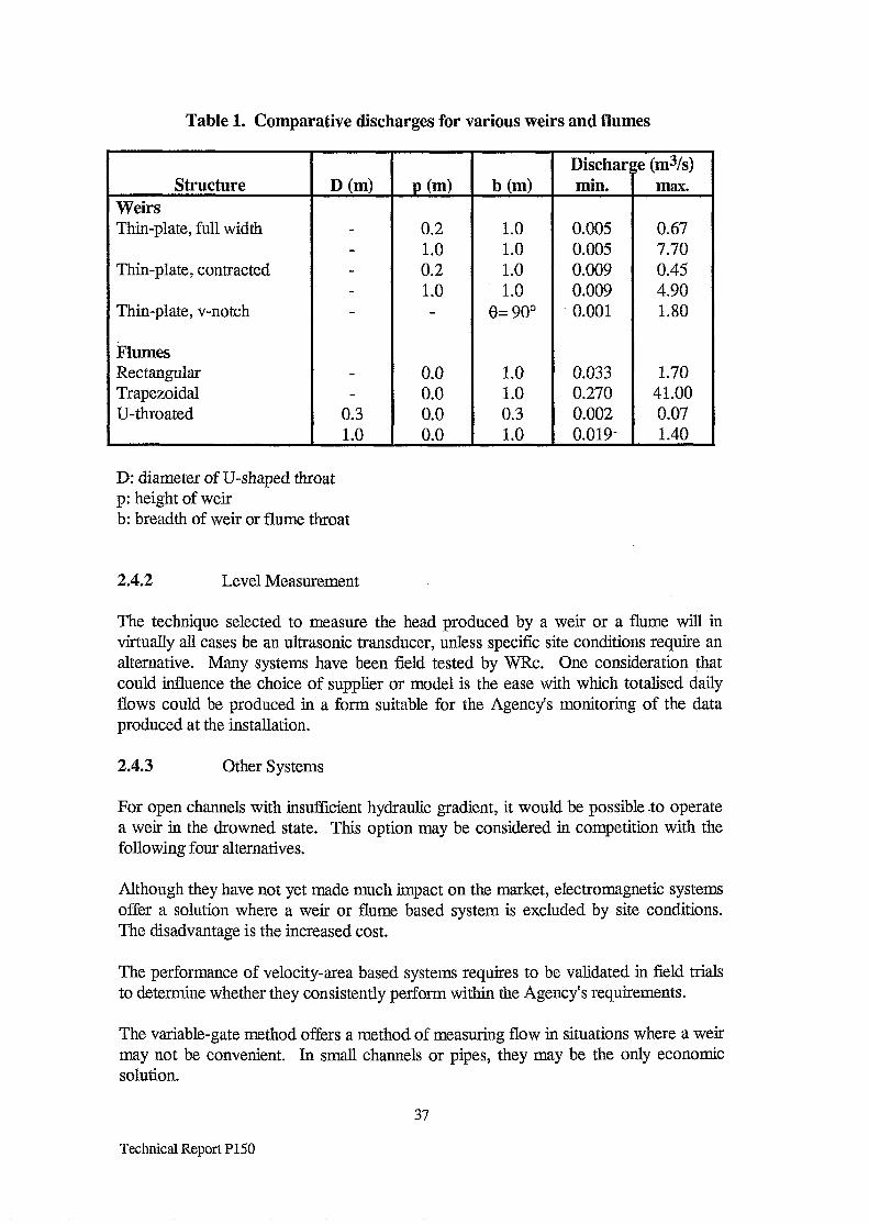
Table 1. Comparative discharges for various weirs and flumes
Structure Weirs Thin-plate, full width
Thin-plate, contracted
Thin-plate, v-notch
Flumes Rectangular Trapezoidal U-throated
D (ml
0.3 1.0
P (4
0.2 1.0 0.2 1.0
0.0 0.0 0.0 0.0
Discharge (m%) b (ml min. max.
1.0 0.005 0.67 1.0 0.005 7.70 1.0 0.009 0.45 1.0 0.009 4.90
e= 90” 0.001 1.80
1.0 0.033 1.70 1.0 0.270 41.00 0.3 0.002 0.07 1.0 0.019- 1.40
D: diameter of U-shaped throat p: height of weir b: breadth of weir or flume throat
2.4.2 Level Measurement
The technique selected to measure the head produced by a weir or a flume will in virtually all cases be an ultrasonic transducer, unless specific site conditions require an alternative. Many systems have been field tested by WRc. One consideration that could influence the choice of supplier or model is the ease with which totalised daily flows could be produced in a form suitable for the Agency’s monitoring of the data produced at the installation.
2.4.3 Other Systems
For open channels with insufficient hydraulic gradient, it would be possible -to operate a weir in the drowned state. This option may be considered in competition with the following four alternatives.
Although they have not yet made much impact on the market, electromagnetic systems offer a solution where a weir or flume based system is excluded by site conditions. The disadvantage is the increased cost.
The performance of velocity-area based systems requires to be validated in field trials to determine whether they consistently perform within the Agency’s requirements.
The variable-gate method offers a method of measuring flow in situations where a weir may not be convenient. In small channels or pipes, they may be the only economic solution.
37
Technical Report P150

For. low. flow rates, a tipping bucket may be the only rsolution offering accurate .. measurement.
At sites where the selection of. an appropriate flowmeter is proving problematical, the option of taking the flow through a closed pipe (whether pumped or not) should be considered.: If an electromagnetic instrument ,is used to measure the flow. rate, an 2 : accurate and reliable measurement can be made with. the advantage of minimal regular 1’ maintenance. The disadvantage, would .be the cost of installation; and also .operating ,. costs if an added pump were required.:
38
Technical Report P150

3.0 : CLOSED PIPE FLOW
Although there. are several Standards relating -to closed pipe: flowmeters, the detailed design of the instrument ,..is the responsibility .of- the manufacturer. : There is no document generally accepted as a detailed specification for the- installation. and operation of, closed pipe flowmeters.. The design of the complete flow measurement system should be such. that .it can achieve the Agency’s specification of uncertainty detailed in section .l. 1. The information -in this section. follows several British Standards, mainly BS 7405..
Historically,. a considerable amount of work on the topic, of streamlined flow (also called laminar flow) was performed by Reynolds. ‘This -is a phenomenon best described by example. Suppose a thin filament of coloured liquid is introduced into a quantity of water flowing through ,a smooth glass tube.. The paths of all fluid- particles will be parallel to the tube ,walls and therefore the coloured. liquid travels in a straight line,. almost as ifit were a tube within a tube. However, this state is velocity- and viscosity- dependent and-as velocity is increased, .a point is reached (critical velocity) when the coloured liquid will appear to disperse and mix with the carrier liquid. At this point the motion of the particles of fluid: are not all parallel to the tube !walls ?,but have a transverse- velocity also: This form of flow ‘. pattern is called turbulent flow. Summarising therefore, for velocities below the critical velocity, flow is said to be streamlined or laminar and for velocities above the critical value flow is said $0 be turbulent - this latter situation is-most common in practice.
Reynolds discovered that these properties were associated with the diameter of the. throat 1 of. the installation, the velocity, the. density of the fluid : and the absolute.: viscosity. He formulated his data in a dimensionless form as the Reynolds number.. Flow of fluid,in pipes ‘is expected to be laminar if the Reynolds number is less than. 2000 and turbulent if it is greater than 4000. Between these values is the critical zone;
Viscosity is the-term used to describe the frictional resistance that exists in ,a flowing : fluid. Briefly, the particles of fluid actually in contact with the wallsof the channel are at rest, while those at the centre of the channel move at maximum velocity. .Thus,, the layers of fluid near the centre that are moving at ,ma.ximum velocity will be. slowed down by the slower moving layers and the slower moving layers will be speeded up by,:. the. faster moving layers. It .is viscosity that is responsib&for the damping out or suppression of flow disturbances caused by bends and valves in a pipe; the energy that 1 existed in the swirling liquid is changed into heat energy.
The velocity across the diameter of a pipe varies and the distribution is termed the velocity-profile of the system For laminar flow the profile. is parabolic in nature, the. velocity at the centre of the pipe- being. twice the mean velocity. For turbulent flow, after a sufficient, straight- pipe .run, the flow profile-- becomes fully developed where velocity.at the centre of the pipe is only: about 1.2 times the mean velocity and is the preferred situation to allow accurate flow measurement.
To achieve the accuracy specilied by the ,manufacturer, the velocity profile -has to be free of~significant distortion. When this condition is satisfied, the’velocity .profile is said to .be fully developed. -*The distortion in velocity profile is removed by allowing
39
Technical Report P150

the fluid to flow along a length of straight pipe and allowing the effect of viscosity to damp out the distortions. The length of pipe is referred to in terms of the pipe diameter. For instance, an upstream requirement of 1OD for the meter installation requires that the straight length of pipe upstream of the meter is without any obstruction for ten times the pipe diameter.
3.1 Measurement Methods
The advantage of the following types of flowmeter (electromagnetic and ultrasonic) is that they have no moving parts and do not restrict the flow. This means that the maintenance requirement is low and there is no extra cost due to increased pumping requirement. The only proviso is that the meter tube should be full at all times.
Al.1 Full Bore Electromagnetic
3.1.1.1 Basic description
When a fluid moves in a magnetic field an electromotive force (e.m.f.) is generated in accordance with Faraday’s law. If the field is perpendicular to an electrically-insulated pipe, which contains the moving fluid, and if the electrical conductivity of the fluid is not too low, a voltage may be measured between two electrodes on the pipe wall. This voltage is proportional to the magnetic field strength, the average velocity of the fluid, and the distance between the electrodes. Thus the velocity and hence the flow rate of the fluid may be measured.
The electromagnetic flowmeter consists of a primary device through which the process fluid flows, and of a secondary device which converts the low level signal generated by the primary device into a suitably standardised signal. The system produces an output signal proportional to volume flow rate (or average pipe velocity).
Its application is generally limited only by the requirement that the metered fluid shall be electrically conductive and non-magnetic and that the primary device will be full at all times.
3.1.1.2 Primary devices
The primary device of an electromagnetic flowmeter consists of the coils used to produce the magnetic field, a yoke of ferromagnetic material, the meter tube through which the fluid flows, and the electrodes. The primary device will also contain, when necessary, circuitry for deriving the reference signal which measures the magnetic field being produced.
The coils and the yoke are arranged to produce a magnetic field through the meter tube. The meter tube is of a non-magnetic material such as plastic, aluminium brass or non-magnetic stainless steel. An insulating lining is used with metallic tubes to prevent the metal tube from short-circuiting the signal. The lining may be of glass, elastomer, plastics, ceramic, etc. The materials used for the lining and the electrodes are chosen to be compatible with the fluid to be metered.
40
Technical Report P150

Flanges are usually provided at each end of the meter tube to connect the primary device to the plant pipework, althoughflangeless meters are available in smaller sizes.
The coils -producing the’magnetic field may be energised from the normal single-phase supply, .or by some other supply.- The coil assembly is mounted either- externally, or encapsulated within the pipe.. In the latter case, the pipe- may be made”of magnetic material.
A pulsed .d.c. meter is one in which the field windings of the primary .device .are energised from a constant voltage or current, source and employs an output signal : sampling. technique .which rapidly differentiates between ,the pure flow signal and any other spurious signalswhich may be present,
Usually the bore of the meter tube will.be the same as that of the adjacent pipework,- If in this case the axial velocity corresponding to the maximum flow rate is less than that recommended by the manufacturers, a primary device with a smaller bore should be used. A primary -device with a bore- smaller than that of the- adjacent-.pipework may also be used for other reasons; e.g.- to reduce cost or in the’interest of rationalisation. Information on the allowable tolerances for matching the pipe and meter. tube ! bores is given-in BS EN 29104.
3.1.1.3 Secondary devices
The secondary device contains the circuitry which extracts the flow signal from the electrode signal and converts it to a standard output signal directly proportional to the.. flow rate. This equipment may be mounted on the primary device..
Early versions of this type of meter used the standard mains supply to energise: the coils. Later versions more commonly use a.pulsed d.c. signal to energise -the coils. The main advantage is that it eliminates zero ,errors automatically at all times and zero adjustment is not usually : required- during commissioning or at any time during.-.-- subsequent operation;.-
The manufacturer’s instructions should be carefully followed for interconnection between the primary,device and the secondary-device.
3.1.1.4 System output
The system output can be one or more of the following :
(a) Analogue direct current ;
(b) a frequency output in the .form of unscaled pulses or scaled pulses (i.e. 1 pulse per .. litre) ;
(c) digital. !
41
Technical Report P150
3.1.1.5 Basic theory
The derivation of the formula to calculate the voltage generated by fluid flowing through a magnetic field is fairly complicated as it involves two non uniform fields. The velocity of fluid within a pipe varies with the distance from the wall. Also, a constant magnetic field strength is difficult to achieve. The special case of two uniform fields is usually quoted in the literature describing the principle of operation of the electromagnetic flowmeter. However, once an electromagnetic flowmeter is designed and constructed, it can be calibrated at a suitably-equipped test house, using clean water as the fluid. When installed in the test pipework, water is forced through the meter at known velocities and the output signal monitored. It is found that the signal is proportional to average velocity and to the magnetic field strength. These data are used to produce the calibration curve of the meter which is the graph of the output versus fluid velocity (magnetic field strength will be constant). The best straight line fit of the data is derived and the slope of the line is called the calibration factor. Thereafter, any flowmeters constructed to the same design should give the same calibration factor. Any variations in calibration factor will -be due to the difXerences -in tolerances during the manufacturing process.
When purchasing a meter, the user can accept the standard calibration factor, or if traceable accuracy is required, the unit can be calibrated in water to produce a calibration certificate specific to the meter purchased. Standard practice is for the meter to be calibrated with clean water. It is assumed that the calibration curve is not affected by the presence of solids in the fluid subsequently being measured.
3.1.1.6 Effect of velocity distribution
Ideally, the magnetic field would be so arranged that the calibration factor is always the same, irrespective of the flow pattern. Though the manufacturers are striving to attain such an ideal, the velocity profile does affect the accuracy of commercially available flowmeters. In practice, when a flow velocity profile which is significantly different from that in the original calibration is presented to the electrode plane, an electromagnetic flowmeter may exhibit a shift in calibration. The arrangement of pipe fittings upstream of the primary device is one of the factors which can contribute to the creation of a particular profile. Bends, junctions, reducers and valves are the most common causes of change in calibration factor,
The disturbance in velocity profiles is usually removed by viscosity effects in a length of straight pipe. The manufacturers can provide recommended clear upstream distances from obstructions so that the effect is minimised. These are generalised in Table 3. Errors induced by pulsating pumps, although not commonly encountered, can cause serious problems.
The effect of Reynolds number is usually so small that for practical purposes it can be ignored.
42
Technical Report P150

3.1.1.7 Effect of liquid conductivity
If the electrical conductivity of- the liquid is uniform in the measuring : section of the meter, the electric .-field distribution is independent of. the liquid-. conductivity ’ and therefore the meter output ..is generally. independent ‘I of. the liquid : conductivity. Minimum operational conductivity requirements. should .be obtained from the manufacturers. Most will quote a minimum conductivity of 5 PLS ..cm-J. Special techniques are required for conductivities down to 0.05 jXS cm-l,
The internal impedance of, the primary device depends upon the liquids conductivity, and very-large changes in this impedance may produce errors in the output signal. If ,:. the conductivity is not uniform throughout the meter, errors may also. occur. A heterogeneous fluid composed of small particles uniformly .distributed in a medium can be considered as a homogeneous liquid..
Deposition of electrically~conductinglayers on the inside surface of the,liner may also lead to errors.
3.1.2 Insertion Electromagnetic
The insertion electromagnetic flowmeter-is based on the same principle of operation as the full bore electromagnetic flowmeter; but is constructed in theilform of a probe mounted on an srm.. The probe is a velocity measuring ;-device -and accurate :. measurements require that the probe axis is.aligned with the direction of the-local flow velocity. It can be used as a means of surveying the velocity profile in a stream.~ It is most advantageous- when the. fluid composition is such that equipment utilising a propeller: or a turbine is inappropriate.
The probe can also be inserted in a pipe if a suitable- tapping,is available.- It could then be used either as a cost effective alternative to installing a full-bore meter or it.could be used on an intermittent basis.
3.1.3 Ultrasonic 2 Transit Time
Ultrasonic waves travel in a medium with a speed of sound relative to, the medium. The frequency and wavelength of the ultrasonic wave are- related .by the ,following equation :
c=fa
where c is the velocity of sound in the medium (in m/s); f is the frequency (in Hz); h is the wavelength (in m).-:
TWO i ultrasonic transducers are attached to the opposite sides of .a pipe, one downstream of the other. An ultrasonic signal.is transmitted through the fluid at an angle to the flow. The transit time of the signal is dependent on the velocity of the fluid-through which it travels. . ..If two transit times are measured,, one with the sound
43
Technical Report P150

going against the fluid flow and one with the flow, the difference will give an estimate of the fluid velocity. These differences are in the region of a few milliseconds.
The equation for the difference in transit times is exact for the average velocity of fluid in the plane of the path between two transducers. However, this value of velocity is different from that of the average velocity of fluid in the pipe.
The frequency of the ultrasound employed is a compromise between beam divergence, which for a given transducer size decreases with increased frequency, and attenuation, which in clean fluids goes up as the square of the frequency. The frequencies used in transit time flowmeters for liquids are in the region 1 MHz to 5 MHz. The minimum Reynolds number of 5000 means that the meters are used in turbulent flow conditions.
Transit time flowmeters are constructed as spool piece devices, wetted sensor kits or clamp-on devices.
In spool piece devices the ultrasonic transducers are.mounted in recesses in the wall:of : the spool piece.
Wetted sensor kits enable users to install transit time flowmeters into existing pipework. Holes are drilled in an existing pipe and the transducers are then welded or clamped into position.
Clamp-on flowmeters employing transducers mounted on the outside of the pipework enable non-invasive flow measurement to be .made.
There are two designs of electronic system commonly used with transit time flowmeters. These are known as the leading edge system and the sing-around-system. The choice of system is for the manufacturers. There are no signilicant advantages’ for the user in either technology in terms of selecting the most appropriate flowmeter.
In fully developed flow profiles, errors can occur as a consequence of pipe surface roughness, unknown Reynolds number, or profile uncertainty in the laminar/turbulent region. In practice, it is difficult to ensure a fully developed flow profile, since even after long lengths of straight pipe thermal effects or minor irregularities can disturb the flow profile.
The sensitivity to velocity profile in fully developed turbulent flow can be reduced in a single beam device by the use of an off diameter chord. Multiple beams can produce significantly reduced sensitivity both to fully developed velocity profiles and also to the disturbed profiles found downstream of disturbances such as bend, valves, and pumps. Devices using two, three and four beams are commonly used and systems with up to eight beams are available in very large pipe sizes. Two beam devices are available for pipe sizes greater than 0.05 m The three and four beam devices are generally used with pipe sizes greater than 0.5 m, and eight beams with sizes greater than 3 m.
44
Technical Report P150
3.1.4 Ultrasonic - Doppler
Doppler flowmeters depend on the -shift in frequency of sound .transmitted from a moving source when detected bya stationary observer. They require air-bubbles-or sol&particles within the fluid flow to scatter the transmitted ultrasound. Attempts I have been made to use Doppler. ultrasonic. flowmeters on clean water relying on ..... turbulence eddies to reflect the acoustic energy. Results are reported as being inconclusive.
The equation derived for. this: type of flowmeter shows that ..the Doppler shift is proportional to the velocity pf the’particles reflecting the.sound.- Typical transmission frequencies in industrial Doppler flowmeters are in the region-O.5 MHz to 2 MHz. The Doppler shift: would be typically in the region .of a few hundred Hz.. The minimum Reynolds number of 5000 means that the meters are used in turbulent flow conditions.
The performance of a Doppler flowmeter is influenced by the following :
(a) The nature of the particles from which the sound is reflected, their size distribution, and their special distribution in the flow;
(b) special broadening of the Doppler -shift caused by the transit time- effects of the : scatterers, -velocity gradients within the.flow, the finite width of the beam’and the non-axial velocity components such as turbulence;
(c) thenon-uniformity of the interrogating~beam.and the non-uniformity of weighting fromdifferent scatterers caused by..attenuation;
(d) uncertainty in the locatiorxof the interrogated volume;
(e) shp between the measured phase and the primary phase.
Doppler flowmeters provide ‘a low cost non-invasive method for measuring low concentration flows. The British .Standard states- that they provide a moderately.:’ repeatable though. often inaccurate -measurement and therefore find.better use as flow switches or flow indicators rather than flowmeters. This conclusion is contradicted by the evaluations. performed by WRc which.- report significant improvements in performance of currently-available instruments.
.Doppler flowmeters .a.re -generally. clamp-on devices although- spool, piece devices are .. available.:: .The most common construction is with two piezo-electric crystals mounted side by side. An alternative is-to have the two sensors mounted diametrically. opposite each .other. This latter design has the advantage of defining the scatter&volume to be in the centre of the pipe.
45
Technical Report P150

3.1.5 Non Preferred Technology
The following types of flowmeter are not employed to measure the flow of sewage or fully treated sewage. This is due to the presence of solids which, apart from causing blockages, may cause erosion. These problems will be exacerbated if the waste is biologically active. These types of flowmeter may be utilised at selected industrial sites,
In terms of the total flowmeter market, the most common type of flowmeter is based on a constriction to flow, such as a plate with a hole in it which is significantly smaller- than the bore of the pipe (called an orifice plate). Because the cross sectional area is reduced, fluid flowing along the pipe has to speed up as it goes through the constriction. Consequently, the kinetic energy increases. This will be matched by a consequent reduction in the pressure energy. The pressure drop, usually referred to as the differential pressure, can be used to calculate the flow rate as the flow is proportional to the square root of this differential pressure. After the constriction, the velocity decreases as the diameter returns to the original value: -However,-there will be an irrecoverable pressure loss associated with the constriction.
Although there is a wide variety of differential pressure. devices, the ones likely to be used in for measuring discharges are orifice plates and venturi tubes.
3.1.5.1 Orifice plates
The flowmeter in most common use throughout the world is the square-edged orifice. They can be applied to measure steady flow provided they are used in the turbulent flow regime. The most important features of the design are as follows.
(a) The sharp, square upstream edge. The accuracy achieved is highly dependent on the edge profile which should be inspected regularly to check that it has not become eroded, corroded or otherwise damaged in use.
(b) A cylindrical throat concentric with the pipe bore. Eccentricity of the orifice can result in significant changes in accuracy.
- (c) A flat upstream face and plate thickness to withstand buckling.
There are three types of pressure tapping, depending on application, covered by the British Standard. Reference should be made to the Standard for details.
Some otice plates may be specified with vent or drain holes. The vent hole permits any gas present in a liquid at the top of the pipe to pass through the plate. Similarly, drain holes permit small solids to be flushed through and not accumulate., The diameter of the vent/drain holes will affect the accuracy but the British Standard covers this topic. Where these holes are specified it is important to remember that they are liable to blocking which can affect performance.
46
Technical Report P150

The advantages of the orifice meter are as follows: :
(a) a robust and simple primary device;. (b) low manufacturing cost; (c) easy to install; (d) well-established type of meter and enjoys universal confidence; (e) no need for calibration for standard installations.
The disadvantages of the orifitie meter are as follows:
(1) only 3:l typical flow range; (2) erosion and- damage to the upstream face or edge change calibration; (3) affected byupstream disturbances. (4) significant pressure loss.
3.1.52 .’ Venturi tubes
The venturi tube.is:a differential pressure flowmeter which is favoured where there is a high solids content or a high pressure recovery is desirable:
The constriction can take the. form of a tube in ‘which there is a gradual change .in section between the pipe diameter and the cylindrical throat. After the throat there-is a gradual-increase in section back to the original pipe diameter.
The advantages of the venturi tube compared with an orifice~meter are as follows:
(a) more robust than the orifice plate and less susceptible. to,particulate flows; (b) lower overall pressure,loss than an orifice; (c) less sensitive to distorted velocity profiles and swirling flow; requiring shorter
upstream:straight,lengths of pipe.
The disadvantages of the venturi tube compared with the orifice plate are as follows:
(1) more expensive to manufacture;. (2) occupies more space in the line, perhaps eight pipe diameters in length;- . . (3) the larger sizes are more.difficult to handle; (4) more.susceptible to errors due to burrs or deposits round the throat tapping.
3.1.5.3. Dal1 tubes
A variation of the Venturi tube iis the-Dali tube: which .has a lower irrecoverable pressure loss. Dali is, a Trade Mark .of.ABB Kent Taylor who no ,longer manufacture the meter..
3.1.5.4 Vortex shedding ‘,
Although trials have shown that, at least in the short term, this type of meter can perform with fluids having a high solids content, it is unlikely that these meters wiLl be used for measurement of flow discharges.
47
Technical Report P150

3.2 Performance
An important installation consideration is to ensure that the meter is always full otherwise errors will result. Hence the ideal arrangement is for the meter to be installed in a vertical pipe. In some applications it is necessary to arrange a bypass so that the flowtube can either be cleaned in situ or removed for cleaning.
3.2.1 Accuracy
The manufacturers quote the accuracy of the instruments either in terms of per cent of reading or as per cent of full scale. This topic is discussed further in Section 5.1. The following Table has been extracted from information contained in the British Standards. The trials conducted by WRc tend to confirm these uncertainty figures for ultrasonic and full bore electromagnetic instruments.
Table 2. Performance Factors
R = of reading FS = of full scale
BS1042: Part 3 gives guidance on the effects of specific departures from the correct installation of orifice plates and venturi tubes as described in Part 1. Such departures should be avoided as far as is possible.
3.2.2 Installation Effects
The performance specification published by the manufacturers applies only to steady flow or to flow which varies only slowly with time.
48
Technical Report P150

Flow pulsation can cause: significant~ errors in orifice plates and venturi tubes .for two main reasons:
(a) the flow rate relationship to differential pressure,is non-linear (square root); (b) the secondary device may not measure the true differentialpressure. :
The effects of upstream .:and downstream disturbances have been. documented in BS7405. The following. table is extracted from that Standard ‘which has used information, supplied by the manufacturers. The diversity of these figures -means that 1 some entries in the Table give a range of. values.
Table 3. Installation-Constraints
Electromagnetic
Quoted range of. upstream lengths
OD/lOD .,
Quoted range of !.. downstream.lengths
OD/5D ‘:
Insertion electromagnetic
Transit time ultrasonic ‘.
25D 5D..
OD/5OD 2D/5D ::.
Doppler ultrasonic I
1OD.. 5D
Orifice I
5D/8OD 2D/8D ...
Venturi. I 0.5Dj29.5D 4D.
3.2.2.1 Full bore electromagnetic.: i
Electromagneticflowmeters can be used with a wide range of liquidsand-slurries since different liner, and electrode materials are available;
In general, installation. requirements for electromagnetic,. flowmeters. are among the. least critical for any type of flowmeter.
If the meter cannot be installed -in a vertical pipe; it is -important to orientate the flowtube so that the axis ofthe electrodes is horizontal This avoids the loss of signal due to ,bubbles of gas passing over -the electrode.. It also avoids’ the problem of deposits coating. the bottom of the-meter tube, and therefore:one of the electrodes.
The ideal-installation for any flowmeter is one in which the velocity flow profile is fully- developed but for electromagnetic flowmeters a straight length of pipe 10 diameters long inserted immediately upstream of the flowtube is sufficient to reduce the velocity error-due to a bend or elbow to’less than 1 %: Although the Standard-states that the configuration of the pipework downstream of the flowtube. has virtually no effect on ,:
. . .
-.
.: ‘.
:.
:‘. 1
pi . .
: ‘: . . . . .
:_i; . ::i. ..I:
:,_
49
Technical Report P150

the performance, tests conducted by WRc have shown that the effect of some downstream disturbances can be greater than generally realised.
As with most meter types, ambient temperature and humidity, particularly where the secondary electronics are mounted on the flow tube, should be considered. Row tubes that are liable to become submerged should be chosen with an adequate level of environmental protection.
3.2.2.2 Insertion electromagnetic
As this type of meter is relatively novel, information on installation is sparse. One important feature is that it measures velocity. Therefore the sensor must be aligned correctly in the pipe. When inserted into a closed pipe through a tapping, care must be taken when turning the head to align the sensor. If too much force is used, the head can move on the probe tube, making it thereafter impossible to know when it is aligned correctly. The unit then has to be returned to the manufacturer.
3.2.2.3 Ultrasonic - transit time
Transit time ultrasonic flowmeters can be used to measure plant effluent flow, as long as it is reasonably clean. The performance can be generally good particularly where the zero setting can be checked. The main application for an ultrasonic flowmeter with clamp-on transducers is a portable instrument for measuring totalised flows or flow rates in pipes with no installed flowmeters.
To achieve the specified performance, the velocity profile through the meter must be reasonable. There may be zero drift problems which will necessitate periodic resetting with the pipe flow reduced to zero.
The clamp-on design has a larger measurement uncertainty than units where the transducer is in contact with the fluid. To achieve acceptable uncertainty, information must be available on pipe material and dimensions, particularly the inside diameter.
In general, ultrasonic flowmeters, both transit time and Doppler, can be mounted in horizontal, inclined or vertical pipe. In horizontal and inclined installations, the transducer should not be positioned in a vertical plane, otherwise the transducer faces can be affected by solids or gases.
The ultrasonic flowmeter is sensitive to the velocity profile of the fluid through the meter. Most manufacturers quote requirements of at least 1OD of straight pipe upstream and 5D downstream, but this minimum upstream length has been shown to be inadequate for single beam systems.
It has been found that deposits on the inside surface can create poor acoustic transmission or deflection from the expected path length. It has also been found that pipes manufactured with a granular structure (e.g. concrete and cast iron) are likely to cause ultrasound dispersion and consequently most of the sound will not be transmitted into the fluid and performance x$U be poor. The existence of such
50
Technical Report P150

problem my not. Xlways be apparent to the user ‘when employing -clamp-on instruments.
3.2.2.4 Ultrasonic - Doppler
Doppler. type.ultrasonic flowmeters work well with raw sewage;- sludge, plant effluent and dirty process liquids.
Because :of their potential as clamp-on anon-intrusive flowmeters; Doppler type instruments tend to be used on unsuitable applications. This is particularly true when- high performance claims. are made. Consequently they have achieved a very poor- ; reputation apart from simple applications such as flow indicators or switches. In some cases, the region of flow-interrogated, and so. the velocity measured,; may change with
’ the concentration of particles.
The previous comments about pipe material and conditions -for transit time flowmeters . . also-apply for Doppler flowmeters.
3.2;2;5 Non preferred technology
All the standard differential pressure pritnary devices can be mounted ,in horizontal,- : : inclined, or vertical pipes as long as the pipe is full at all times. For an orifice plate, the sharp edge-must face upstream; If the plate is installed the wrong *way round, the indicated flow will be,about 20 % below the true flow.
The upstream and downstream straight pipe length requirements .. are specified in ‘: BS1042: Section 1.1 for the most common types of .pipe -fittings. Since- the venturi tube- is less susceptible to disturbed velocity profiles. and to swirling flow than are orifice .plates, it generally requires shorter straight pipe, lengths. For all types of primary device, BS 1042: :Section 1.1 gives alternative shorter straight pipe lengths that can be used, providedan additional 0.5 % uncertainty is added arithmetically. to the , uncertainty in Table 2.
3.2.3 Type of Fluid
A limit .of the application of the electromagnetic flowmeter is that the fluid .must be electrically condutitive. The minimum conductivity required by. the electromagnetic flowmeter. varies between manufacturers, but the conductivity of sewage and fully treated effluent .in the U.K. will always be above the minimum..-: Fluids ranging from potable water to concentrated concrete slurries have proved, to be suitable. The meters are available with the flowtube .and :transmitter assembled as one. unit or as two separate entities. The advantage of the former arrangement is- that. it minimises the stray.impedance due to the connections to the electrodes and hence enables the system to function satisfactorily on a liquid-With a conductivity down, to the lower limit.
Time of flight flowmeters are designed for use with clean liquids where they find their major application... However, the trials performed by WRc have shown that they are reliable .when used with sewage..
51
Technical Report P150 ::

The main application of the ultrasonic Doppler flowmeter is on pipes carrying liquids containing sufficient proportions of either bubbles or solids to give strong reflected signals. They are unsuitable for very clean liquids unless the turbulence level is high enough to obtain a signal. As the facilities capable of performing the wet calibration of a flowmeter use clean fluids, this type of meter tends not to be wet calibrated in practice.
Differential pressure devices should be used with relatively clean fluids although venturi tubes can be used in the presence of solids. Sewage is not an appropriate fluid as it is biologically active and the pressure lines would be liable to become blocked. The use of this type of instrument would therefore be restricted to specialist trade wastes.
3.2.4 Minimum Flow and Operating Range
The rangeability is defined as the ratio of the specified maximum to minimum flow rates. This is sometimes referred to as the- turn-down ratio. Table.-2 shows the rangeability achieved by the various types of flowmeter. Although it may be noticed that the rangeability of differential pressure devices is poor, they may be used in situations where a pump, or several pumps, are either on or off. Then rangeabihty is not an important criterion. The detition does not state whether the uncertainty at the minimum flow is the same as that at the maximum flow. Also, the maximum flow used to detie the rangeability has a velocity that tends to be a factor of about three times higher than that used to pump waste fluid.
Both ultrasonic and differential pressure flowmeters should be used in the turbulent flow regime whereas the performance of electromagnetic flowmeters is not seriously affected by changes in Reynolds Number.
Although some instruments will have a low flow cut off, the high rangeability will mean the consequences are less likely to be critical.
3.2.5 Calibration and Maintenance
The Agency should encourage the discharger to adopt the attitude of planned preventative maintenance. The attitude of “maintenance on failure” will result in long periods of lost data. Current predictive maintenance techniques do not appear promising although for ultrasonic instruments there are some ideas being developed in research organisations.
For closed pipe flowmeters there are no facilities available to the user to adjust the reading. Any adjustment should be performed only by the manufacturer while the meter is installed in a NAMAS accredited flow test facility. In setting up the instrument, there may be some parameters that need to be set to convert the reading to the volumetric flow rate.
When the calibration factor is determined by a wet calibration using water in the test facility, this is performed at reference conditions, i.e. at constant ambient and fluid
52
Technical Report P150

temperatures and constant. humidity with- a mains supply which: experiences. no deviations in voltage or frequency.
For electromagnetic flowmeters, maintenance costs should be minimal. Normally no maintenance other than periodic checking, or re-ranging is required. Where build-up of deposits on the electrode is a recurring problem, electrode- cleaning can also be carried out in-line via ultrasonic or burn off cleaning, methods. In some designs;- removable electrodes are available.
For electromagnetic flowmeters, as is the case with :most flowmeters,. there amno generally accepted recommendations as to when periodic recalibration should occur: .. In aninstallation where-it is possible’to stop the flow, the signal at zero flow can be measured and, if possible; adjusted. This operation should not be necessary for pulsed d.c. meters.- Many manufacturers can provide a calibration unit for “dry calibration!‘. -: purposes.. This can be used to. check the performance of, the secondary device but.. cannot be used -to calibrate the primary device. The calibrator can, at the same time, be used to check the operation of the relays and telemetry- It is recommended .that-this operation should be undertaken at frequent intervals (Table 4).
For differential pressure flowmeters, both primary and secondary devices need regular .. maintenance to ensure reliability. and the lowest possible uncertainty. The secondary part of the system, the differential pressure sensor, can be isolated without the need to shut -down the line. The sensor, can then be. calibrated. It -should .be noted that “calibration” in this instance does not include .the primary device.- When orifice plates are used in fluids with corrosive or abrasive properties, frequent inspection is essential to. check that the square-edge remains sharp. Pressure tappings. also have to be checked frequently. if. there is any possibility of them becoming blocked.
The following Table shows suggested maintenance -intervals (months) when. using sewage or sewage effluent. Practical experience, has been used in the construction of i this Table as there is no specific information in the-Standards.
Table 4. .-Maintenance Schedule (months)
k3tallation type Visual On-site-., Full: Replacement- inspection calibration inspection
X$ : :
’ ‘:a
Electromagnetic 12 12 60 120 -.240 :_ :.;;:
Ultrasonic :: 12 12 : 60 120 -240, i Orifice .:’ fj :. 6 12 120. A!. :.’
Venturi. 6 6 60 120’ ‘Y
BS 1042: Section 1.5‘ points out that for orifice .plates and .venturi tubes, inspection periods will be dependent on the nature of the fluid being metered and the manner of operation,. of the. system -in which the. meter is installed, and can only be determined from experience.
53
Technical Report P150

3.2.6 WRc Field Trials
The Water Research Centre has performed various evaluations of flowmeters at an operational sewage treatment works. The data obtained by WRc are not comparable with the manufacturer’s claimed performance for several reasons.
(1) The manufacturer uses clean water to determine performance. It would appear that if fluid containing sewage is used, the random error is increased.
(2) Both the ambient and fIuid temperatures are controlled at the test facilities used to generate the manufacturer’s performance data as are the mains voltage and frequency. In the WRc trials, these are left unconstrained.
(3) The data used by the manufacturer are gathered over a few hours. The duration of the WRc trial is 12 months.
(4) The manufacturer was not permitted to -adjust > the instrument once. the. trial commenced. If a manufacturer can adjust the instrument when installed at a test facility, the subsequent data do not reflect the systematic error potentially introduced by the calibration procedure adopted by the manufacturer.
In the 1980’s, WRc reported that the electromagnetic instruments showed a total error over the 12 months of between 1.5 % and 3 %. The total error over 12 months for transit time ultrasonic instruments was 8 % and for the Doppler ultrasonic was 11 %.
In the 1990’s, development in flowmetering techniques has shown significant improvements. The total error for electromagnetic instruments has reduced to 1 %; the ultrasonic transit time instruments have between 2 % and 5% error; the Doppler instrument included in the trial recorded better than 5 %.
These figures have been obtained too recently to be incorporated in the British Standards. It must be admitted that the performance reflects the quality of the design rather than the inherent capability of the principle of operation.
3.3 In Situ Calibration
Various techniques can be used to calibrate flowmeters. The approach adopted in the British Standards is to employ a technique whose uncertainty is a factor of three lower than the uncertainty required of the flowmeter. Closed pipe instruments that have been installed correctly and are fault-free, have an expected uncertainty which is likely to be lower than that of the in situ calibration techniques. However, calibration can be used as a method of identifying whether a significant fault exists.
The methods described earlier for tracer techniques and drop testing are also applicable in closed pipes. When the flow is pumped from a well, this is an ideal situation to perform a drop test. Also, the flowmeter does not need to be calibrated over the full range as only those flows achieved by the pumps are the suitable calibration points.
54
Technical Report P150

There are other techniques available, but are unlikely to be employed due totheir high cost;, Either a portable (trailer-mounted) meter prover or a transfer standard meter, could be coupled into the line and fresh water pumped through the pipe to the meter.
In the case of closed pipes running full,~ there are further possibilities for verifying the ! flow rate. The accuracy of the following techniques may not be as good as that expected of the,meter being calibrated. As such;’ the procedure cannot be classed as a calibration, but rather as a confidence check.
3.3.1 -. Clamp on Ultrasonic Meters
Ultrasonic :clamp-on meters have recovered their credibility since. the first; designs became available. Modern : units-. have complex diagnostics to aid setting: .up;- Manufacturers- of clamp. on instruments use both :. time. of .transit :and Doppler techniques.
It. should be remembered from the earlier description:-- of. their operation. that the ; velocity of flow measured may.not be the true average velocity. This also means that : the instruments are prone. to errors: induced -by velocity distributions that are- affected by upstream.and downstream conditions;
An additional problem is that to convert the signal to a volume flow rate requires the .- true diameter of the pipe to be known. If there is an error of x % in the estimation of’. the diameter, the contribution to the .error in flow rate computation is 2x %;- Some-. modern instruments claim to be able .to ‘determine the pipe,.wall thickness. N’ith the outside diameter -,of the-.pipe being easily measured, this l-wall thickness gives an indication of the inside diameter of the pipe. There may be an unresolved question as to their ability to cope with a pipe which has a build up of relatively soft material. reducing the effective diameter.
Instruments -using the time of transit principle are liable to be more e accurate than Doppler based instruments. Modern, equipment will monitor the strength of the i acoustic signal,, which can be used to improve the confidence in the reading .of the flow rate.-
Transit time clamp on equipment, is now often used in surveys of installed~ flowmeter’ performance. Such equipment has. been used by the author to determine. pump efficiency at a sewage pumping station;: The equipment used had been tested at a NAMAS accredited facility and had been demonstrated to have an uncertainty of +/- 3 % of reading. However, -this was using water as the test fluid a&having more than 50 diameters of clear pipe. upstream,of the measurement location. Also the- pipework &as clean and the internal diameter known. In general, an estimated uncertainty for time of : transit clamp on flowmeters would be +/- 5 .% under. the best conditions with. the.: uncertainty increasing if problems due.: to installation effects are anticipated or the ; pipework: is not. in the best condition.. Doppler: based instruments may. have an uncertainty of +-/- 5 % (based on WRc trials).-
55
Technical Report P150

3.3.2 Insertion Electromagnetic
The insertion electromagnetic probe has been designed so that it can be inserted through a valve fitted to a pipe. Techniques exist to attach (by welding) the required valve to an existing pipe.
In a small pipe, the size of the probe may be significant when compared to the cross sectional area of the pipe. This forces the fluid to speed up as it meets the restriction caused by the probe. Consequently, the measurement has to be adjusted by a “blocking factor”. These factors have been determined experimentally and have been tabulated. In large pipes, the blocking effect is minimal.
Various points can be chosen for the location of the probe in the pipe. The probe could be positioned to measure the velocity at the centre line where the velocity should be in the region of 1.2 times the average velocity for turbulent flow. Alternatively, the probe can be positioned at the distance from the wall at which the velocity should be the same as the average. If the highest accuracy--achievable %-required,-the-velocity profile can be measured by traversing the full diameter of the pipe using the probe as a velocity meter. It may be necessary to perform a second traverse at right angles to the first before selecting the optimum location for the probe.
The insertion electromagnetic flowmeter can be use in one of three ways :
(1) a survey tool to investigate flowmeter performance;
(2) a temporary installation to measure flows for a short time;
(3) as a permanent installation when the consequences of installing a full bore instrument make the insertion option attractive.
3.3.3 Insertion Turbine
Insertion turbines have traditionally been used to calibrate flowmeters using water. They have been designed to be inserted through a valve.
Many of the problems identified in the previous section for insertion electromagnetic probes are also experienced by insertion turbine instruments. Blocking factors may need to be considered. The optimum location may require one or more complete traverses to be performed.
The turbine exhibits a low flow cut off at which point the bearing friction will completely stop the turbine from rotating.
The main problem with this type of instrument when installed in a waste line is the fact that any debris in the flow is prone to attach itself to the turbine blades. Thereafter, the results are of dubious value.
56
Technical Report P150

3.3.4 Full Bore Electromagnetic
As noted earlier, many:- manufacturers can provide a calibration unit for “dry calibration” purposes. This can be used to check the performance .of the secondary device but cannot be used to calibrate the primary device. The calibrator can, at the same-time, be used to check the operation of the relays and telemetry.
3.3.5 Differential Pressure
As noted earlier, the secondary part of the system,- the differential pressure sensor,. can be isolated without the need to shut down the line.. The sensor can then be calibrated. It should be noted that .“calibration” in this instance. does not include the .primary device..
The cost of removingan existing orifice plate,for calibration at a NAMAS accredited : facility is likely to be substantially greater. than that of replacing .the plate. It may be more convenient to remove the orifice plate when it has been.decided to inspect it. A replacement, either new or re-furbished, could be immediately fitted, reducing down time. The plate could be inspected later, and a decision taken to discard or refurbish.
3.4 Selection of New Flbvmeter.
When selecting a new flowmeter,. ‘economic considerations are likely to take precedence. The costs will not just- be capital (design, construction,’ installation, commissioning).as operating costs may be significant. It ,is the- responsibility- of the discharger to make the appropriate decisions; It-is theresponsibility of the Agency to ensure that the performance of the meter should satisfy the.rlgency’s specification. If- c:. the discharger selects a type of system that requires fi-equent maintenance, and: this. maintenance is neglected, this would be a cause for concern within the Agency;
The performance and reliability of electromagnetic flowmeters has been demonstrated over the last twenty years. For a discharge- flowing in a closed pipe; there. are- no obvious reasons not to select an electromagnetic,.instrument for a new flowmeter installation. The expected performance would be-the same as that reported by WRc. The size at which the cost advantage of a time. of transit ultrasonic instrument becomes important is unlikely to be encountered in closed pipe discharges.
Economic considerations may also favour.the use of clamp:on or insertion instruments.
If, for whatever reason, the. decision needs .more consideration, BS7405 should be referred to as it is devoted to defining:.the processes to be followed in selecting- a flowmeter.
Site specific. conditions may influence the .size .chosen, .but as this is largely an economic argument, and covered in BS7405, this topic will not be expanded here. The only item of interest would be the maximum and minimum. flows; especially.. the magnitude of the measurement-uncertainty at the minimum flow.
57
Technical Report P150

4.0 .’ FLOWMETER.INSTALLATION
4.1. Location of Flowmeters at Sewage Treatment Works
In considering a proposed flow measurement. system at a site, ,the Agency will have regard for the cost to the discharger in relation to the information needs of, the Agency. This allows room for. compromise.. For instance, at a weir which is occasionally drowned at high river flows, the cost ,of an alternative system might be high- and i produce no significant benefits for the environment. -,.Any decisions taken on this basis. have to be explicitly stated, both in the internal report and in the report sent to the: discharger. If. there is a case where it is subsequently-suspected that a change to the’ discharge,is causing a problem in the receiving watercourse after the standards have been relaxed, this decision must be re-considered.
The Agency will-give priority to flowmeter installation at sewage treatment works if either the flow is believed to be close to or above their flow-consent limits and .those works which sign&army affect the quality of the receiving, water;
Flow rates can be: measured at any. suitable. location before--discharge. The location 1: must be agreed by the Agency. Outlet monitoring will be required for discharges where an instantaneous flow limit for the discharge is necessary.
4.1.1 Final Effluent
The ideal location for the flowmeter would~ be just before the final discharge point to ... the watercourse. This-is.fairly common at small works equipped-with anopen-channel flowmeter whose discharge point is visually obvious. It would be possible to envisage 1. a situation where surface run-off from the site could also discharge to the watercourse without being-measured. .However, such flows, which will .also include wash water : used to clean vehicles, should in all cases be returned to the head. of a the works to receive full treatment.
If the works is accepting substantially more.flow than was planned at the design stage,. there may be a problem with- the. primary device,.
4.1.2 Flow to Treatment
The discharger. may expend more effort ensuring that the meter measuring thetflow to full treatment is in good condition, as this measurement may be used. for operational reasons. The discharger may wish to negotiate with. the Agency- the acceptance of this’ ; measurement instead of the measurement of final effluent..
Technical Report P150

The flow to treatment may differ from the flow at the final effluent point for several reasons.
(1) The flow to treatment will exceed the flow to tinal effluent by the volume of sludge produced. This means that the former will be an over-estimate of the latter. The difference will be in the order of 1 % of daily flow if only primary settled sludge is wasted. If the primary sludge is co-settled, the volume of surplus activated sludge will be in the region of 2.5 %. This latter figure will be reduced if the sludge is de- watered.
(2) If surface run-off is pumped to the works inlet, the discharge point should be upstream of the point at which flow is measured.
(3) Other discharges, such as effluent from the administration buildings, should also be returned to the upstream point.
(4) If there is any other water pumped to the works inlet, such asproduced by a sludge. press, this water has already been measured and need not be returned upstream of the flow measurement point. Such flows are unlikely to have a magnitude of consequence.
(5) If the works accepts input from tankers, such as septic tank contents, these should be measured.
(6) The storm tanks are emptied at a convenient time when the incoming flow is reduced. This flow should be measured, either separately, or returned to the works flow upstream of the meter measuring the flow to treatment.
In conclusion, the flow to treatment is likely to be a reasonable estimate of the discharge flow once the operation of the works has been verified.
4.1.3 Storm Flow
The Water Companies have a duty to treat sewage up to a maximum .flow. This maximum is calculated using “Formula A”. This is contained in a report of the Technical Committee on Stoma Overflows and the Disposal of Sewage whose iinal report was issued in 1970. This formula is now used in preference to the six times dry weather flow figure used previously.
The dry weather flow (DWF) has three components contributing to the total. These are the domestic population connected flow, where P is the domestic population connected and G is the per capita flow, the infiltration, I, and trade discharge, E :
i.e. DWF=PxG+I+E
The minimum flow that must receive full treatment is usually three times dry weather flow. This is calculated as follows :
3DWF=3xPxG+I+3xE 59
Technical Report P150

For combined or partially separate sewerage systems, flows greater than 3 DWF, up to a maximum defined by Formula. A, ‘must- receive. some. level of treatment. This S treatment is agreed by the Agency for each works, the minimum being- screening, with storm settlement being. the most common additional requirement.
Formula A defines the maximum flow. as follows :
A=DWF+1.36xP+2xE (units are m3/day)
Flows greater than Formula A are liable to cause problems -in the sewer system ‘i Therefore the excess may overflow the sewer at selected points.:. It’is assumed that these flows are dilute enough to be discharged without treatment. These discharges are discussed in Section 4.4.
These calculations do not use the concept of population equivalent. ,The Urban Waste Water Treatment. .-Directive defines l- population equivalent- as the j organic.: biodegradable load having a biochemical oxygen demand of 60 g of oxygen per day, and on this definition-is therefore not explicitly flow related.:.;.;
A simple. side weir could,be used to allow flows greater than 3 DWF to overflow from the channel leading to full treatment. If the height of this weir was set at the depth when flow equalled13 DWFit might, be assumed that.this was sufficient. This would be true if the average velocity. of the flow remained constant as the volumetric flow increased. .But if the average velocity-increases, the flow passing to treatment (which is the channel width times the weir .height times the average flow velocity). will also increase. Therefore; a greater flow : than ..3 DWF will then go to treatment. Consequently the side .weir -crest might., be set somewhat below 3 DWF to ,prevent. excess flows ‘under full storm conditions. A penstock controlled by a downstream. flowmeter is commonly used.ato control !the flow to --treatment- under storm flow conditions..
The ideal measurement situation i would occur if there were two. flow measurement locations. The difference between the flow to the works and the flow. to treatment would give. the storm-flow. Also,. thisdifference would be integrated so that once. the storm tanks are full, the rate of overflow could be calculated. An additional advantage of having these two flow measurements is that when no storm flow exists, the two flow rates should be identical provided no other flows were: introduced between the points of.measurement. Any variance would be indicative of measurement error.
If,a flume is used to measure the storm flow, it will; in general terms;, be similar in size to the flow to treatment flume: The minimum flow corresponds to a minimum.depth of 50 mm In storm conditions, this flow may have sufficient duration for a substantial,. flow to pass which.may fallinto the low’flow cut-off region. In such circumstances, a trapezoidal flume will be more appropriate than a rectangular flume. As an example, consider. a 800 mm wide channel fitted with a 300 mm rectangular flume. Peakdepth of 500 mm corresponds to a flow of 178 l/s. The flow at the minimum depth of 50 mm is 5.2 l/s. If a trapezoidal section flume were installed,- the peak flow would be 160 l/s ;’ and the flow at the minimum depth of 50 mm would be 2.0 l/s.
60
Technical Report P150

Overflows from storm tanks are not regularly measured. Currently in the UK, there is no obligation to provide flow measurement data for discharges at sewage treatment works due to storm flow conditions.
The Agency may require dischargers to install event recorders to record the frequency, date and duration of operation of storm discharges. The requirement will normally be a temporary arrangement and the Agency will review the need for each installation from time to time.
In some situations, the requirement to protect the quality of the receiving water will justify the provision of further facilities. If immediate notification of the operation of a discharge is needed to enable the discharger or the Agency to take urgent action to protect water quality, then a telemetry alarm should be installed.
4.1.4 Sewer Discharges
As discussed in the previous section, there are overflowpoints,built into thesewerage: system. These discharges into the environment are under scrutiny in several countries, particularly the southern states of the USA and Germany. The recognised problem that is anticipated is that the public perception will be once the main discharges are well controlled, the largest impacts on the river environment are agricultural run-off and storm overflows.
The cost of changing current policy is likely to be high. It has been estimated that of the 25000 discharges, 35 % are unsatisfactory. The current situation should be reviewed by the Agency.
The policy of the Agency is that intermittent discharges will require as a minimum, spot checks and may require event recording of the frequency and duration as well as the flow information. Several companies can supply equipment to note the f?equency and duration of the discharges and also have the capability of storing this data until unloaded. The measurement of flow rate is liable to be expensive and the Agency will require provision of this information in specific, site dependent, circumstances.
4.2 Industrial Discharges
Industrial discharges are less likely to rely on open channel types of flowmeter. Although it is anticipated that electromagnetic instruments will commonly be installed, there may be situations where other options have been considered appropriate.
Flow measurement of rainfall related discharges such as site drainage will only be required if the Agency considers it necessary for effective control and is concerned that the polluting potential of the discharge could cause a significant water quality impact.
Industrial sites which have installed a computer for process control will probably have linked the discharge flowmeter into the system The incorporation of the calculation of the.total daily flow may not yet have been installed.
61
Technical Report P150

Problems. may be encountered- at smaller sites where the economic viability .of the operation makes the‘provision of additional monitoring equipment- difficult.- ” In such instances, the Agency will stress the importance of Compliance and any associated time scale.
62
Technical Report P150
5.0 DATA HANDLING
5.1 Overview..
This. section describes the requirements .for the .provision of-flow information by .the discharger and also describes how the Agency will handle : this information. . . It is importantto acknowledge that the quantity of-information required for each site will involve staff time and therefore costs which will be borne both by. the dischargers and by the Agency. Dischargers will be required to make returns of the information to the Agency at regular intervals. For most discharges, annualreturns will be appropriate, although.more frequent returns may be requested where there is a specific need;
Where information is being-.provided to confirm the setting of storm overflows or the. frequency of operation of storm overflows,.then- the discharger should provide the data to the Agency. This should be accompanied, .if necessary, by a report explaining what action is proposed if the data shows consent requirements are not being met.. The report should be,provided to a time scale required by theAgency.:- For regular reports, ’ the normal frequency will be .annually. -Only exceptionally, will the discharger be required to install telemetry monitoring and immediate reporting to the Agency.
A substantial effort will also be.required to record site data in a manner that facilitates retrieval -when required.. To <minimise the expenditure. of effort in implementing the scheme; it is important that a systematic approach is adopted. Consequently,- a series of forms will be created to collate site information. Their content and organisation-is covered in section 6.
Although the system. archive will initially be based on written files, the volume of- information, and the need to access the information from various sites, will justify:the : expenditure of effort in creating’ a data base. It may be prudent. to consider the implications of forming a data base when finalising.the design of the.forms.
A large, and growing; quantity of data will be generated by dischargers. To control the..requirement for staff, the. Agency should, ensure. that the .specification for data transfer remains under the control of the Agency.
The techniques associated with data transmission are predicted to change dramatically over the .next few years. The use of Internet techniques is being, actively studied -by business users such as banks, and it is anticipated that these techniques will dominate the market early in the next decade. .The discharger may take the attitude that giving.. the Agency the required password information so that .it can access the .data meets. the requirements of disclosure of data.
As has been stated in Section- 1.1, the defining e performance criterion. is that the flowmeter installed shall achieve a total uncertainty- better than +/- 8 % for a daily totalised flow over the lifetime of the meter while appropriate: maintenance schedules are being operated.- For the purposes of this document, the total uncertainty includes .: all equipment up to the creation of the data file transmitted to the ,Agency.
63
Technical Report P150.

This criterion has some important consequences.
In the WRc trials, the accuracy data was collated over the duration of the trial which was 12 months. The daily totalised values required by the Agency will inevitably reduce the random error to some degree; e.g. due to totalising 96 flow rate measurements.
Secondly, the flowmeters tend to be less accurate at low flows. The effect on the daily total may be reduced. As an example, if the uncertainty of flow is +/- 20 % of reading at 10 % of full scale, this would appear to be greater than the Agency requirement of +/- 8 %. However, this corresponds to an uncertainty of +/- 2 % of full scale. If the average flow is 25 % of full scale, the uncertainty at this flow rate is +/- 8 % of the average flow.
Also, when the accuracy of the instrument is quoted as a percentage of full scale, the relationship between the average flow and the full scale will become important. As an example, if the uncertainty of flow is +/- 2 % of full scale; at first sight it would appear that this complied with the accuracy requirement of the Agency. But if the average flow is 25 % of full scale, the uncertainty of all flow measurements is +/- 8 % of reading, and the uncertainty of the total daily flow is +/- 8 %, only just complying with the requirement.
5.2 Flow Rate
It is assumed that at each point of discharge, a flowmeter exists which has as a minimum, an analogue output signal proportional to the flow being measured. Obsolete systems would have comprised a clockwork driven chart recorder using a pen to record flow rate. It is assumed that such systems are no longer being operated. If any such system is being used, the totalised daily flow information would be extracted from the chart record by a laborious manual method. This would be the responsibility of the discharger. The Agency will not accept chart records.
The analogue signal, usually a 4 - 20 mA current loop may be used for
(1) local control;
(2) connection to telemetry for transmission to a regional centre;
(3) connection to an on-site SCADA system.
Many systems offer the capability of adjusting the zero (4 mA) and full scale (20 mA) signals. Equipment used to adjust the signal should possess a current NAMAS certificate.
In general, daily flows will be required, but the Agency can specify whether instantaneous flow rates are also required.
64
Technical Report P150

5.3 TotaliSed Flow
The Agency requires the- totalised flow over a.24 hour period, which is most likely to be midnight to midnight. Some. flowmeters; mainly sophisticated versions of those used for open channel flow, have a facility to integrate the -flow and store-each daily total. The starting time for the 24 hour period is user selectable. Some instruments can totalise the flow, but the individu&daily totals are not stored in the~instrument (this feature is fairly common in closed .pipe instruments). Instead,. the totalised reading has to be observed and manually. recorded. Such manual.operations are unlikely to be suitable in future due., to.. staff costs. Such systems are. likely to be recorded during the normal working day and are therefore unlikely to be recorded at midnight.- To reduce the staffing. requirement, ..it may be that such systems ‘are currently read once per week and the totals .for the :week divided by 7 to give the mean daily discharge. This last procedureis not acceptable to the Agency.
Many, but not all, flowmeters are designed to produce integrated, or totalised, flow measurements. Those instruments equipped with this facility require> to..be- set up in terms-of units and scale factors;
If the flowmeter doe not have the facility. to,calculate and store 24 hour totalised flows, and is neither connected to SCADA nor telemetry, another option must be found. Either it has to be replaced by a flowmeter possessing this capability or a separate unit, which monitors the analogue signal and produces a daily totalised reading, has to be addedto the system. .The latter option is likely to be cost -efficient.except where the meter is already scheduled for replacement;
As the capability of modern electronic equipment: has increased, there is a temptation’-.- for the’ ‘manufacturer to provide more and more facilities. The capability, of -current data loggers is an instance of this. What is required in the case of flowmeters is a fairly. simple data logger with a single input channel. The requirement is to either record the instantaneous -flow measurement at an interval of, say, 15 minutes, or to average the reading electronically over the same period,before recording: the average value.’ These individual readings could.. be stored. for .24 hours .a and then the total. daily flow computed. It would also.be possible to create a record of the maximum and minimum : flow during that period. During a subsequent site visit, it would be possiblebto transfer these records. The current technology would suggest using either a portable personal computer or a specifically-designed piece of hand held equipment. such as a Psion. Future trends would suggest the data would : be archived -using a removable . card, similar to a credit card. “These records could later be used to create the .data ‘file: required by the Agency.
With most data loggers it would also be possible to have a connection to a regional or site location which could receive- the, daily totals; This is unlikely to be an option because a telemetry system would be.able to transmit the flow rate measurements, and b. the receiving computer could calculate the daily totals, thereby eliminating the need for the data logger-completely. Some outstations connected to telemetry systems have a facility for calculating the .total daily flow.
65
Technical Report P150
A point that may be worth considering is whether the totaliser is capable of being reset so that the total daily flow measurement is an under-estimate of the true figure. Some meters have a totaliser which cannot be reset in addition to recording the individual daily totals. This would be useful in areas of dispute.
Common symptoms of a problem with the flowmeter are a zero flow signal, or a constant value replacing the standard variability. The Agency will produce a system to automatically identify these conditions in the received data so that action can be initiated.
5.4 Connection to Telemetry or SCADA
If there is a SCADA system on site, it is probable that this could be used to totalise the flow rate. The SCADA system will regularly record the flow rate of any flowmeters connected to the system The SCADA computer could be programmed to totalise these signals to produce the total daily flow. In many, but not necessarily all, sites using a SCADA system this totalisation facility may already bein existence:
Also, many Water Companies are installing telemetry systems so that the information is available at a regional centre. For instance, the largest scheme in the UK is that implemented by Anglian Water. This has over 7000 outstations (at treatment works, reservoirs and pumping stations) with a design capacity of 12000. As in the case of the SCADA system, the computer could be programmed to totalise these signals to produce the total daily flow or the integration of daily values can occur within the outstation.
In both these instances, the reason for the flow measurement may be to manage the operation of the works. The measurement of interest may be the flow to treatment in preference to the flow being discharged. Section 4 considers the implications of the siting of the flowmeter.
Both SCADA and telemetry systems may be able to record the concentration of some quality parameter and the associated flow rate, and hence calculate the instantaneous load. The equipment will therefore be able to calculate the total daily load from these individual load values. This may be more appropriate than multiplying the-total flow by the average concentration.
In exceptional circumstances, the discharger will be required to install telemetry monitoring and immediate reporting to the Agency of intermittent discharges such as storm overflows.
5.5 Data Received by the Agency
Dischargers will be required to make returns of the information to the Agency at regular intervals. For most discharges, annual returns will be appropriate, although more f?equent returns may be requested where there is a specific need. The Agency will specify for such sites whether daily flows are required or whether instantaneous records are also required.
66
Technical Report P150

The information will normally be- provided to the Agency in a computer compatible form agreed by the Agency by direct electronic transfer or on a disc, according to local arrangements; The consequences of direct electronic transfer will be studied further by the Agency.
The Agency will satisfy itself that the complete data trail from flowmeter to computer record is identified and is satisfactory. The data trail will include.some of the following
l the analogue signal from the. flowmeter - such as 4 to 20 mA proportional to flow rate including scaling factors adjusted during commissioning;
l the conversion.of the.analogue signal to a digital form in a telemetry or SCADA .. outstation. The accuracy of this. conversion can .be confirmed using calibration equipment, (which should possess a current NAMAS certificate); ::
l the integration of the flow signal in the outstation;
l the integration of the flow signal within the telemetry or SCADA system;-.
l low flow cut-off; does this featureaffect all parts of the data trail identically;
. effect of power failure at various locations;
l any manual recording of integrated total,
0 pulse generation within-flowmeter - each pulse generated after a set volume;
l internal or external summation of pulse signal;
. unloading of the data from.the flowmeter to a portable computer;
. unloading of data from portable computer;
0 creation of data file to be sent to the Agency.
There are a number of topics that must be addressed before the system-is in operation. It may be prudent to,discuss some of these with the discharger, especially in the case of the Water Companies. It is assumed that any computer-compatible information received by the Agency will; without exception, be:.“virus checked”:
Any. system producing the data in computer-compatible :form-. and also the system receiving the data,!must be “2000 compliant”.
Each’ site should.have a specific .identifier, not just a site name, to ensure that the data from one site cannot be. mixed with ‘the data from another. I The..discharger has probably a potential solution to this problem.
The format of the.data should be specified so that the Agency can use the flow data to calculate the-load.
67
Technical Report P150

6.0 OPERATION OF.SELF MONITORING SCHEME..
6.1 Audit Procedure
The Agency will ensure that the transmission of all documents, both sent and received, will be recorded using an appropriate scheme. A systematic approach will ensure c that any updating of information is correctly recorded. For instance, when, the initial response to the request- for information is received, it must be copied. ! This working. copy can be used while the original is filed.
6.1.1 Initial Collection of Information
The Agency has records of each consented discharge which willinclude the person or organisation responsible for the discharge and the limits placed on that discharge.. The Agency will on’ a region, -by. region basis ..identify‘ an appropriate officer to .be responsible ‘for the implementation. and- enforcement of the policy. This may be a different person for the initial introduction. and the ongoing, enforcement:... Provision. will be made by each area for archiving the flow data provided and running compliance programmes;
The Agency will then write to each. discharger enclosing ~the audit forms: Experience in auditing flowmeters. has demonstrated the absolute necessity for formalising~the procedures, wherever possible; by., the ‘use of standard forms. The topics to be addressed in the covering- letter and these forms are documented .in -the Appendices; This-letter stresses the importance of receiving a reply within a specified time scale.
At the commencement of the scheme,.it is envisaged that a manual filing system will be employed.
At some point, it will become-more efficient to record the information on a database.- Such a decision may-alter the structure of theraudit form,. but the information required will not differ appreciably.- One problem that has been encountered in converting from. . a file based system to a data-base has been questions which have beenanswered by the inspection team in longhand. .If care is not exercised in the design of the form.and’the entries to the data base, there may be no method of incorporating this information, and hence the information may-be discarded.,
It is anticipated that data storage and transmission is about to undergo dramatic. changes which may. reduce the:problems. Some techniques discussed in the erchiving and retrieval of information and data. by .the Agency may quickly become obsolete; However, the requirement for -site-~specific details and flow records. will remain the. same, despite.advances in &available technology.
6.1.2 Assessment,of Initial Response
It is anticipated that a committee will be required to assess the responses.
Flow monitoring .,should- be supported by evidence that the uncertainty of the flow metering device is no greater than +/- 8 % (with regard to daily total flow).
68
Technical Report P150

Several Water Companies have already instigated an audit of their flowmeters measuring the discharge from sewage treatment works by independent third parties. Evidence of such an inspection will be considered in deciding how to categorise the installation.
The committee will grade the responses under the following categories :
l installation appears to fully meet the requirements and no first inspection required. The Agency may wish to confirm this conclusion by a subsequent site visit, but this work can be scheduled after the sites with acknowledged problems have been tackled;
l installation is unsatisfactory and further work by the discharger is imperative;
. insufficient information to categorise installation.
In the latter case, a second letter may be required.3 the- committee concludes that. the : discharger has the complete information, but has omitted to return it. Alternatively, a telephone call may be sufficient. If this option is taken, a record of the conversation must be kept and documented later for transmission and confirmation by the discharger. Once a reply is received, the installation can be classed as satisfactory, or not. If at this stage there is insufficient information, a site inspection may be judged as a suitable method of resolving the situation. However, this will require extra staf? time to be provided by the Agency. An alternative solution would be to issue a notice that the system installed is unsatisfactory and request remedial action. If the discharger believes that the target level of accuracy is not achievable at a reasonable cost at a site, then it must satisfy the Agency that this is the case and that it has used the best available technology.
>P ~.
When an installation is classed as being unsatisfactory, the areas of dissatisfaction must be detailed to the discharger and a plan of remedial action will be requested with associated time scales. Once the remedial action has been performed, the Agency must decide whether a site inspection will be required.
6.1.3 Organisation of Site Inspection
It is inevitable that some installations will need to be inspected. Although the site audit form will in general detail the required information, there may be occasions that require additional information on topics deemed appropriate by the committee due to specific site peculiarities. This will be particularly true of installations that do not conform to the British Standard.
Inefficient use of staff time (both for the discharger and for the Agency) is to be avoided wherever possible. If an audit of a site were organised by the discharger, the information should be gathered using forms similar to, but more detailed than, those in the Appendix. Information would need to be gathered on many more details to ensure fiu-ther work could be detailed if required. The requirements of the Agency are more restricted, and only those needs should be addressed.
69
Technical Report P150
If a detailed- inspection of. an open channel primary device is deemed .necessary, the equipment detailed in section b2.3.4 must be provided by the team performing the: inspection. -It would be prudent to ensure that.photographic:records of each site were obtained by the team as an aide memoire. If a digital camera were used; the pictures could be scanned into any database. In case of inclement.: weather, it may. be considered prudent to have a Dictaphone available so that observations could be conveniently recorded. ‘I It would also be prudent to have encased the audit sheets so that they can be consulted in inclement weather..
Problems have arisen at sites being i audited,. particularly sites which are .not manned during normal working hours. Particular attention should be paid to the following :
l time, date a&location of visit to be-agreed by both parties;
l the representative of the discharger to possess all required keys and codes;
l the contact may not be able to answer all questions:<
The contact may be chosen by the discharger to allow access. There may be operational questions’-to be answered, such’ as flow depths,’ process flow routes, maximum historical flows, diurnal flow patterns, pump operation; These should have been. answered at the. audit form stage, but additional problems ,.rnay be identified during the.site visit. Another problemthat might be experienced is when the contact.is in possession of the necessary information concerning the flowmeter installation;- but is uncertain of the operation of the telemetry system.
There may -be specific instrument problems. The flow rate -reading. may not be accessible because :
0 there is no local display;
l the local display is located in an area forwhich access has not been requested and/or granted,
l the instrument is not set to display the flow rate at the time of the visit and would need the.inspection team to. interfere! with the instrument: to obtain a reading. This : responsibility should be left with the discharger.
If .‘the result .of the site inspection is that the installation is classed as being unsatisfactory, the areas,of dissatisfaction must be detailed to. the discharger and a plan of remedial action will be requested.: Once the remedial action has been performed, the Agency must decide whether a second site inspection will.be required.
6.2 Procedure after ,Satisfactor.y Audit
6.2.1.. Internal-Report Generation
The audit forms have been produced to collect information in a structured form. The assessment of the information will follow this structure; The information analysis that : :
70 ‘,
Technical Report P150
demonstrates that the installation complies with all the requirements will be filed with each site.
Two internal reports must be generated, The first will detail the observations that should be made by the person conducting the sample collection. This topic is covered in section 6.2.3.
Secondly, the flow data will need to be scrutinised. Each daily total should be compared to the maximum in the consent. Lost data should be noted as a cause for concern. Whether the flow rate is consistently close to the consented flow rate or consistently close to the full scale of the instrument could also be noted. In this context, “close” is defined as above 90 % of maximum These analyses will be used to assess compliance against the flow limit in a consent. The data will be supplied in a computer compatible form so that the generation of these reports should be relatively simple. The staff costs associated with handling the data and producing these reports will be borne by the Agency. The Agency may wish to consider the implications of allowing internal access (on a read-only basis) to these--data files- using ,an Internet based system.
One topic in section 6.2.2 states that the discharger must update some site details if changes are made. The Agency staff required to make these amendments need to be identified. If use were made of the Internet, it would be possible to give the discharger access to the appropriate file so that the amendments could be made directly.
If such systems are in place, the discharger may wish to send the data using the Internet. In this instance, the Agency must ensure that the data is in a form suitable for mathematical manipulation.
6.2.2 Report sent to Discharger
As discussed earlier, the Agency will write to the discharger. The topics to be covered in this report are :
. site details including method of notifying the Agency of any change in contact details;
l whether the flowmeter is to be a permanent installation or whether the site has the meter installed on a temporary basis;
l daily totals required and what 24 hour period covered;
l interval between reports, i.e. whether annual or more regularly;
l whether flow rates will be required;
l whether the Agency needs to be informed of high flow rates, i.e. by telemetry;
l procedure if problems arise with the installation such as failure or replacement of the meter;
71
Technical Report P150
l proposed maintenance schedule;
l the discharger is to be informed that the staff of the Agency may visit to inspect the operation of the. meter. This may be during a standard. visit concerned with sampling, or may be at a time selected by ,the Agency;
l the consent has been amended to include the statement concerning the.provision of ,.’ data. ‘.
It would be appropriate to devise a report sheet with areas and boxes to be filled in as appropriate for each .site. This would .ensure the information2 was presented in a systematic manner, and. may assist in .any Quality Assurance. schemes to be implemented in the future..
6.2.3 Internal Report to Sampler
On a site-by site basis, a list of tasks to be undertaken by the person-collecting samples will be generated. This person is unlikely to possess expertise’in flow measurement systems. The tasks will probably be :
. note the flow rate at the time of visit;
0 note the integrated flow totals where available;
. inspect the’ documentation Ion site- to confirm that the proposed- maintenance schedule has been performed.
The returned information; and whether any action will be required by.the Agency, must .. then be incorporated in the datafile.for the site..-
Again, if the Agency decides ‘to use the Internet as a means of communication, the sampler could use this as a means of listing the tasks for a site, but also as a means of communicating the observations.
6.3. Subsequent -Inspection
Once a site is perceived as being satisfactory, it is anticipated that further inspection by Agency staff will be performed during a visit. to collect. samples. The information required is detailed in the preceding.. section. These site visits will be-.the primary source of information on the operation of the flowmeter. The flow data produced by the discharger will also be scrutinised for problems by the Agency. The Agency has the authority to adopt a random inspection of the discharge flow.measurement system to ensure continued compliance with the requirements of the Urban Waste Water Treatment Directive.
72
Technical Report P150

References.
British’standards
The latest version-of these references should always be used. The versions quoted were current in the BSI,index available’in March 1998.
1. BS1042Section 1.1. (Renumbered as BS EN IS0 5167-1:1997,‘equivalent to EN IS0 5167-1:1995,’ IS0 5167-1:1991). Measurement .of fluid.flow in closed conduits. Section 1. Pressure~differential devices. Section 1.1 : Specification for square-edged orifice plates, nozzles and‘venturi .tubes inserted in circular cross section conduits running full;
2; BS1042: Part: 1: Section ,,1.4:1992. Measurement of -fluid: flow in closed. ..I’ conduits.. Section 1.4 Guide..to the use of devices specified in Sections’ 1.1 and. 1.2.
3: BS1042: Part 1: Section 1.5:1987. Measurement of fluid:. flow in closed.: ,- conduits.. Section 1.5; Guide to the effect of departure -from the conditions . . specified in Section- 1.1.
4. BS3680:Part 1:1991 (IS0 ‘772:1978). Measurement of liquid. flow in ?open . channels; Part 1. Glossary. of Terms.
5. BS3680:Part 2A:1995 (IS0 9555-1:1994). Measurement of liquid flow. in open ,,.. channels. Part 2A. General.
6. BS3680:Part 2B:1993 (IS0 95552:1992). Measurement of.liquid flow in open .‘- channels. Part 2B. Methods of,measurement.using radioactive tracers.
7. BS3680:Part 2C:1993 (IS0 9555-3:1992):,Measurement of:liquid flow in open channels. Part 2C. Methods of measurement using chemical tracers.
8. BS3680:Par-t 2D:1993 .(ISO 9555:4: 1992). Measurement of liquid flow- in open channels. Part 2D:. Methods of measurement using fluorescent tracers.
9. BS3680:Part 3F:1986 (ISO- 1088:1986). Measurement, of .liquid flow in open channels. Part 3F.. Velocity-area methods,- collection and processing of .data for determination of errors in measurement;.
10. BS3680:Part 3G:1990‘(ISO 8363:1986). Measurement of liquid flow -in open channels. Part 3G. General Guidelines for the selection of methods.-,
11. BS3680:Part 3H:1993 (IS0 9213:1992). Measurement- of liquid flow in open channels;‘.Part.3H. Electromagnetic method using a full-channel-width coil..
73
Technical Report P150
12. BS3680:Part 4A:1992 (IS0 1438/l). Measurement of liquid flow in open channels. Part 4A. Methods using thin-plate weirs.
13. BS3680:Par-t 4B:1992 (IS0 4360:1984). Measurement of liquid flow in open channels. Part 4B. Triangular profile weirs.
14. BS3680:Part 4C:1992 (IS0 4359). Measurement of liquid flow in open channels. Part 4C. Flumes.
15. BS3680:Part 4D:1989. Measurement of liquid flow in open channels. Part 4D. Compound gauging structures.
16. BS3680:Part 4E: 1990 (IS0 3846-1977). . Measurement of liquid flow in open channels. Part 4E. Rectangular broad-crested weirs.
17. BS3680:Pai-t 4F:1990 (IS0 4374). Measurement of liquid flow in open channels. Part 4F. Round nose horizontal broad-crested weirs.
18. BS3680:Part 4G:1990 (IS0 4377). Measurement of liquid flow in open channels. Part 4G. Flat-V weirs.
19. BS3680:Part 4H:1992 (IS0 8368-1985). Measurement of liquid flow in open channels. Part 4H. Guide to the selection of flow gauging structures.
20. BS3680:Par-t 9A:1986. Measurement of liquid flow in open channels. Part 9A. Specification for the installation and performance of pressure actuated liquid level measuring equipment.
21. BS5792:Part 1:1993 (Renumbered as BS EN IS0 6817:1997, equivalent to EN IS0 6817:1995, IS0 6817-1992). Measurement of conductive liquid flow in closed conduits. Method using electromagnetic flowmeters.
22. BS5844:1987 (IS0 5168-1978) (Publication of revision is imruinent). Methods of measurement of fluid flow. Estimation of uncertainty of a flow rate measurement.
23. BS5857:Part 1:Section 1.1:1986 (IS0 2975/l-1974). Methods for measurement of fluid flow in closed conduits, using tracers. Section 1.1 General.
24. BS5857:Part 1:Section 1.2:1986 (IS0 2975/2-1975). Methods for measurement of fluid flow in closed conduits, using tracers. Section 1.2. Constant rate injection method using non-radioactive tracers.
25. BS5857:Part 1:Section 1,3:1986 (IS0 2975/3-1977). Methods for measurement of fluid flow in closed conduits, using tracers. Section 1.3. Constant rate injection method using radioactive tracers.
74
Technical Report P150

26:BS5857:Part l:Section-1.4:1986 (IS0 2975/6-1977).. Methods for measurement :.. of fluid flow in closed conduits, using tracers. Section 1.4 Transit time-method using non-radioactive tracers.
27:BS5857:Part l:Section-1.5:1986 (IS0 2975/7-1977). Methods for measurement .t- of fluid flow in closed conduits, using tracers.- Section.1.5. Transit time method using radioactive tracers.
28. BS5875:1980 (renumbered as BS EN 24006:1993, equivalent,to EN-24006-1993, ISO.4006:1991).- Measurement. of :fluid flow inclosed conduits: vocabulary and symbols;-
29. BS7405: 1991; Guide to. selection and application : of flowmeters forthe measurement of fluid flow in closed conduits.
30. BS EN 29104:1993, (equivalent, to IS0 EN 29104:1993, ISO. :9104:1991). .:- Measurement) of fluid, flow in closed conduits; Methods of, evaluating: the performance of electromagnetic flowmeters for liquids.-
Further Reading
31. : Haywood, A.T.J. :,Flowmeters - A Basic Guide,and Sourcebook.for Users. Macmillan, 1979.
75
Technical Report P150

blocking distance broad-crested weirs combined sewer overflow. conductivity crest (of a weir)
14,15,22,27 10;20
differential pressure
3, 16, 19,61 : 40,43,5 1’ 6-10, 22, 23, -26, 28,
34,35,60 .. 5,46-49,51-53,57
discharge coefficient Doppler ultrasonic
7,25,29 5, 17,26,27,45, 48-55
dry weather flow. or DWF electromagnetic
Index
Environment Act .’ flat-V broad-crested weir Flowstick
2, 13,59,60 5, 17; 19, .37, 40-43,
4%54,56,57,61 1
10 19
flume (general) 2,5,6,11-37,60 foam 12;14;.16,26 Formula A. 59,60
head measurement 7, 12, 21, 22, 25, 27, (location) .* 30 .:
insertion 5, 17, 43, 48-50, 56, electromagnetic 57 insertion turbine 56 : low flow cut-off 15, 19,27;52,56,67
Manning formula. 16 NAMAS 4,52,55,57,64 nappe (of a weir) 6-10,22,25,28
performance criterion population equivalent rectangular broad-
,. 1,63,64 2,60
crested weir 10
rectangular flume. rectangular. weir round-nosed broad- crested weir samples secondary device
sediment / silt
storm flow suppressed weir
telemetry
temperature compensation thin-plate weir time of transit (or transit time)
trade discharges. or industrial discharges trapezoidal flume trapezoidal weir triangular weir (or V-notch weir) Urban Waste Water Treatment Directive
2, 11,24,.29,35,60 6,7,9, 10,27,29,35
5 19,72 13, 26, 29, 40,41, 49,
50,53,57 11-14, 16, 26, 28, 29,
35,36 59-61,63 9
3, 53, 57, 61;‘63-67, 70,71’
14,15. 6,7,20,34 5, 17;. 43, 44, 48-51,
54,55,57
2,5,26 .. 11,24,35,60 6 2,6-9,13,20,23,
25-27,29,34,35,37
2,3,60,72
U-throated flume. ll-13,37
variable gate velocity profile
V-notch weir vortex shedding Water Research Centre (or WRc)
Water Resources Act weir box weir (general)
18, 19,29 39, 42-44, 47;50, 51,
56 see triangular weir 47 4, 6, 20, 22, 29, 37,
45,48,50,51,54, 55,57,64
1 7,26,35 4,6-10, 15,20-30,
34-37
76
TechnicalReport P150 .-

APPENDIX A
Suggested wording for-letter. to discharger (Consultthe Agency’s lawyer re wording?)
You are reminded that the Water. Resources Act 1991 (as amended i-by the Environment Act 1995) specifically provides i for conditions in consents requiring the I installation, maintenance and testing of meters to measure-and recordvolume and rate of discharges. It also allows the Environment Agency to -require the discharger to keep records and make returns. As you are responsible for the following discharges :
c list >
Could you complete .the enclosed forms to assist us in this function;: and return the.: forms to- ‘.
bY
c address >
< deadline >
A-l
Technical Report P150
APPENDIX B
AUDIT FORMS
This appendix contains draft -audit forms for use by an Agency Inspector when inspecting a site ..which has a discharge. The information- required is not as comprehensive as would be required if a site audit were being conducted on behalf of the discharger. Information such as : meter age, suggested replacement date, flange size, route of mains,:route of signal cable,.would be required so that the discharger can plan future:work. The prime concern-of the Agency is to assess whether the existing installation is satisfactory. A secondary concern is that the.,Agency has access to. the information so that when there is a change,of Agency staff involved in this topic;: the time required for site familiarisation is reduced to a minimum.
Further. work on these draft forms will be required. Each region maycreate a different system for recording the returned information which may require .modification of these forms. If a-database is employed, the problem of having a question repeated at various locations .on the forms can be,automatica.lly answered.
B-l
Technical Report P150

‘.. . .
-.INSPECTOR
DISCHARGER
: AUDIT ORGANISATION ..:.
( DISCHARGER’S NAME ) METER AUDIT.. :
DATE METER : .L
LOCATION SITEID: I
Site Summary (required regardless of instrument type)
Site name OS reference
Contact name Contact location Contact telephone number Contact fax number : Contact Internet location.
Site telephone number Works manager Hours that the site is manned
Access procedure - quality of information received :: Access problems Hazards
Consented flow Permanent or temporaryinstallation Location of discharge meter
or other meter
Any other process streams to be audited :
AUDIT PERSONNEL- . . DATE TIME.ON SITE TIME OFF SITE ; . .
INSPECTOR : ._ . . -... CONTACT ,::. ,s.
B-l
Technical Report P150

INSPECTOR DISCHARGER
AUDIT ORGANISATION ( DISCHARGER’S NAME ) METER AUDIT
DATE METER
LOCATION SITE ID
Structure Open channel - gauging structure
Flume/weir/broad-crested weir/other Flume type Throat length / throat width / bottom contraction Weir type / box Dimensions - shape / width / height / nappe aerated Details of method other than weir or flume
Dimensions
Channel width / approach length Distance upstream to bend /junction /weir - tick structure Distance to bend downstream / hydraulic jump existing at time of inspection Comments - such as approach conditions unsatisfactory - turbulence
Site information
Maximum / minimum / average daily flow rates Full scale of meter Depth at maximum flow (both calculated and evidence of scum line) Flow at minimum BS3680 depth
Open channel - flow instrument
Manufacturer / model / year of manufacture / installation date / calibration date Blocking distance / distance to top water level Output - local / analogue / pulse / integrator / totaliser - units - resettable / daily totals Location of readout and observed reading Connected to telemetry Low flow cut-off Controlling penstock
Is location secure for transducer mounting Location of sensor upstream of primary device / width & head at maximum flow Location - height over zero (commissioning) Weir vertical / well secured / corroding / edge sharp & bevel in good condition Cleaning record - date Is there ‘an operational check of zero, or other distance - date performed Estimated uncertainty - of zero / height
Sketch and photos i.d. Calibration required - tracer / drop / velocity-area / survey
If audited by independent third party - report
B-2
Technical Report P150
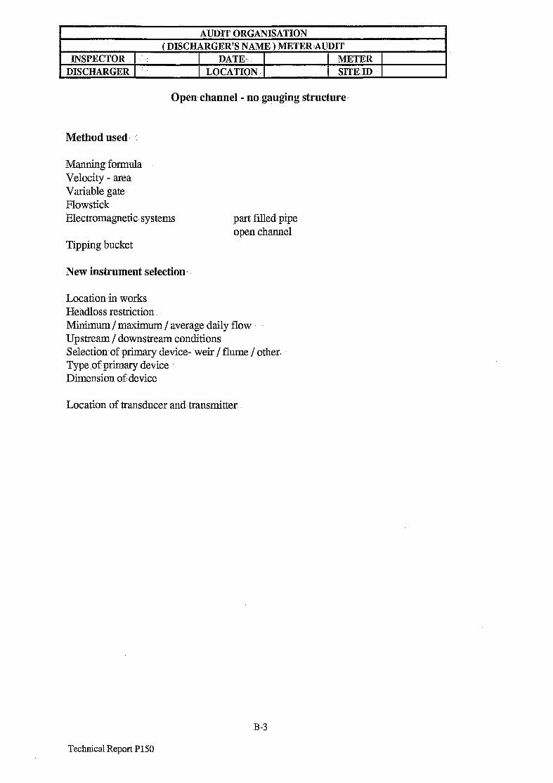
AUDIT ORGANISATION
( DISCHARGER’S NAME ) METER:AUDIT INSPECTOR : DATE,: METER
DISCHARGER :. LOCATION .. SITE.ID
Open channel - no.gauging structure
Method used. :
Manning formula Velocity - area Variable gate- Flowstick Electromagnetic-systems part filled pipe
open channel Tipping bucket
New instrument selection..
Location-in works Headloss restriction. Minimum / maximum / average daily flow Upstream / downstream conditions Selection-of primary device- weir / flume-/ other. Type .of primary device Dimension of,device
Location- of transducer and -transmitter.
B-3
Technical Report P1.50
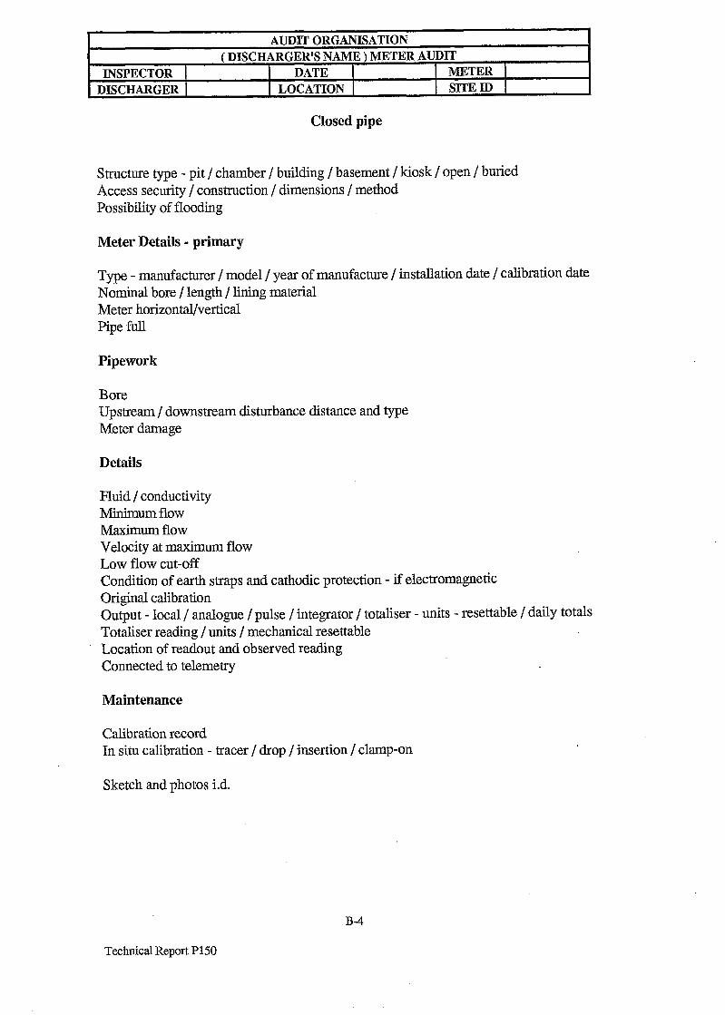
INSPECTOR DISCHARGER
AUDIT ORGANISATION
( DISCHARGER’S NAME ) METER AUDlT
DATE METER
LOCATION SITE ID
Closed pipe
Structure type - pit / chamber / building / basement / kiosk / open / buried Access security / construction / dimensions / method Possibility of flooding
Meter Details - primary
Type - manufacturer / model / year of manufacture / installation date / calibration date Nominal bore / length / lining material Meter horizontal/vertical Pipe full
Pipework
Bore Upstream / downstream disturbance distance and type Meter damage
Details
Fluid / conductivity Minimum flow Maximum flow Velocity at maximum flow Low flow cut-off Condition of earth straps and cathodic protection - if electromagnetic Original calibration Output - local / analogue / pulse / integrator / totaliser - units - resettable / daily totals Totaliser reading / units / mechanical resettable Location of readout and observed reading Connected to telemetry
Maintenance
Calibration record In situ calibration - tracer / drop / insertion / clamp-on
Sketch and photos i.d.
B-4
Technical Report P150
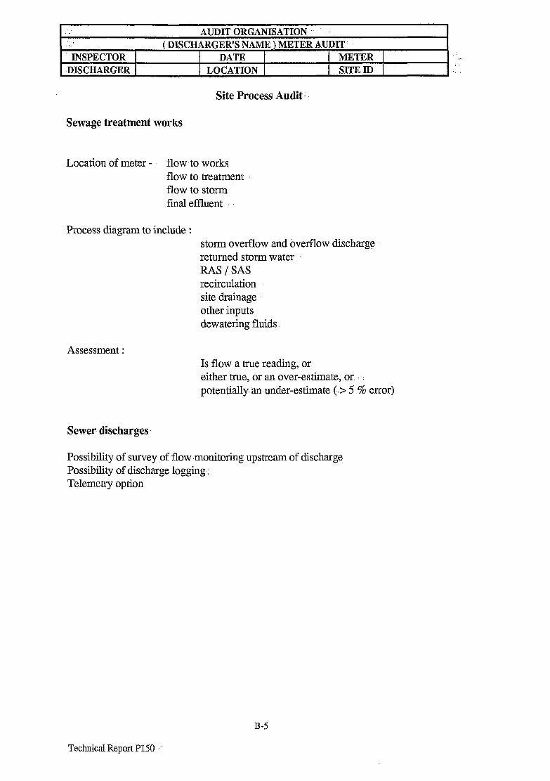
_’
‘I .
INSPECTOR
,DISCHARGER
AUDIT ORGANISATION
( DISCHARGER’S NAME ) METER AUDIT DATE METER I.
LOCATION SITE ID .,
Site Process Audit.
Sewage treatment works
Location of meter - flow to works flow to treatment flow to storm final effluent
Process diagram to include : storm overflow and ovefflow discharge : returned storm water RAS/SAS recirculation site drainage other inputs dewatering fluids
Assessment : Is flow a true reading, or. either true, or an over-estimate, or .: potentially an under-estimate (.> 5 % error)
Sewer discharges
Possibility of survey of flow -monitoring upstream of discharge Possibility of discharge logging: Telemetry option.
B-5
Technical Report P150

INSPECTOR DISCHARGER
AUDIT ORGANISATION
( DISCHARGER’S NAME ) METER AUDJT DATE METER
LOCATION SITE ID
Data trail / data inspection
Who collects data - how regularly Transmission route to the Agency - how regularly
Meter rate integrator daily totals
Analogue output Analogue signal / pulse output Set full scale / set zero /pulse rate Destination - telemetry outstation / SCADA outstation / data logger Calibration check ? Where daily total calculated - meter / data logger / telemetry outstation / telemetry master / process control computer / manual recording How is daily total unloaded to disc / Internet - PC / handheld / credit card system How is Agency file created Effect of power failure
Inspection
Claimed accuracy Evidence Average diurnal flow pattern and average daily flow Full scale flow rate Days per year effectively zero flow Days per year > 90 % consent Days per year > consent Days per year > 90 % full scale Days per year > full scale
B-6
Technical Report P150