flow assurance with ansys cfd - esssesss.com.br/events/ansys2010/pdf/21_7_1750.pdf · flow...
TRANSCRIPT

© 2010 ANSYS, Inc. All rights reserved. 1 ANSYS, Inc. Proprietary© 2010 ANSYS, Inc. All rights reserved. 1 ANSYS, Inc. Proprietary
Flow assurance with ANSYS CFDFlow assurance with ANSYS CFD
Lubeena, RMuralikrishnan, RMohan Srinivasa
Lubeena, RMuralikrishnan, RMohan Srinivasa

© 2010 ANSYS, Inc. All rights reserved. 2 ANSYS, Inc. Proprietary
Agenda
• Introduction
• Flow assurance with ANSYS
– Risk avoidance
– Hydrates
– Sand transport
• Horizontal gas-liquid flows
• Gas liquid flow in vertical pipes

© 2010 ANSYS, Inc. All rights reserved. 3 ANSYS, Inc. Proprietary
Risk avoidance
• Need to ensure
– Operating conditions within envelope of safe operation
• Modeling for risk avoidance
– Fluid flow and heat transfer
– Non-Newtonian rheology
– Temperature dependant properties
– Can perform these simulations with a high degree of confidence
© 2010 ANSYS, Inc. All rights reserved. 4 ANSYS, Inc. Proprietary
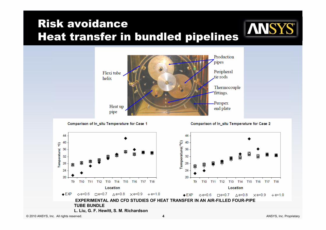
Risk avoidance
Heat transfer in bundled pipelines
EXPERIMENTAL AND CFD STUDIES OF HEAT TRANSFER IN AN AIR-FILLED FOUR-PIPE TUBE BUNDLE L. Liu, G. F. Hewitt, S. M. Richardson

© 2010 ANSYS, Inc. All rights reserved. 5 ANSYS, Inc. Proprietary
Wax and hydrate formation
• Wax formation ≠ clogging
– Flow can alter structure
• Most promising strategy
– Thixotropic visco-plastic
fluid
• Simulations used for
– Stability of wax layers
– Transient start-up
• Coupling with 1D codes

© 2010 ANSYS, Inc. All rights reserved. 6 ANSYS, Inc. Proprietary
HydratesComputational modeling of methane hydrate dissociation in a sandstone coreKambiz Nazridoust, Goodarz Ahmadi, Chem Engng Sci 62 (2007) 6155 – 6177

© 2010 ANSYS, Inc. All rights reserved. 7 ANSYS, Inc. Proprietary
Joule Thompson effect
PUBLISHED RESULTS SIMULATION
Pressure distribution along
shock-tube
Temperature distribution
along shock-tube

© 2010 ANSYS, Inc. All rights reserved. 8 ANSYS, Inc. Proprietary
Ideal vs Real
IDEAL GAS REAL GAS
SUBSONIC
REGION
SHOCK
HEATING
J-T HEATING
SHOCK
NO J-T
HEATING
Mach Number Mach Number
Static Temperature Static Temperature

© 2010 ANSYS, Inc. All rights reserved. 9 ANSYS, Inc. Proprietary
Sand/Particulate Transport
• Sand is often produced out of the reservoir in both onshore and offshore production systems, particularly in reservoirs that have a low formation strength
• Sand production may be continuous, or sudden - as when a gravel pack fails
• The sediment consists of finely divided solids that may be drilling mud or sand or scale picked up during the transport of the oil
• Sand deposition could lead to corrosion of the pipeline
• Problem of sand deposition and re-entrainment– Inclined pipelines, pigging sand plug
pipeline
• Particulate modeling in ANSYS Fluent 13.
0
500
1000
1500
2000
2500
3000
3500
4000
4500
0.5 1.0 1.5 2.0 2.5 3.0
Mean Slurry Velocity, m/s
Me
an
Slu
rry
Pre
ss
ure
Gra
die
nt,
Pa/m
Skudarnov et al, 2001
Newitt et al, 1955
FLUENT CFD - Schiller Drag
FLUENT CFD - Wen & Yu Drag
0
0.2
0.4
0.6
0.8
1
0 0.1 0.2 0.3 0.4 0.5 0.6
Solids Volume Fraction
Y / D
Fluent CFD: dp = 120 um
Matousek, 2002 (dp = 120 um)
Fluent CFD: dp = 370 um
Matousek, 2002 (dp = 370 um)

© 2010 ANSYS, Inc. All rights reserved. 10 ANSYS, Inc. Proprietary
Operating envelope: Gravel packs
• Design criteria for gravel packs
– Minimum pump rate to avoid rat holing
screen out
– Maximum pump rate to avoid
formation fracture
– Need to determine safe envelope of
operation
• Critical velocity/shear stress for settling
Horizontal open hole gravel pack placement requirements in selective completion projects, Anais do ENAHPE 2009
The relevant parameters calculations were only possible via a robust 3D Computational Fluid Dynamics Simulation
(CFD). The application of the critical shear stress methodology for open hole gravel packs design in multizone
completion projects indicates less conservative results which can make possible operations in critical operational
windows scenarios.

© 2010 ANSYS, Inc. All rights reserved. 11 ANSYS, Inc. Proprietary
Terrain slugging
0
10000
20000
30000
40000
50000
60000
4 5 6 7 8 9
Pressure Drop
0
0,5
1
1,5
2
2,5
3
3,5
4
4,5
5
4 5 6 7 8 9
Mass Flow Rate

© 2010 ANSYS, Inc. All rights reserved. 12 ANSYS, Inc. Proprietary
Hydrodynamic slugging
• Hydrodynamic Slugging– Waves grow on the liquid
surface to bridge the pipe
– Kelvin-Helmholtz instability the cause for wave formation and slugging
– Modeling of interfacial instabilities will be crucial
• Problems due to slugging– Fatigue
– High frictional pressure drop
– End of production when low flow rates
– Production slop due to high static pressure changes due to long slugs.

© 2010 ANSYS, Inc. All rights reserved. 13 ANSYS, Inc. Proprietary
Problem Description
• The entrance to the pipeline is arranged to give a stratified flow, in which the
gas flows above the liquid in parallel streams, and slugs originate from
waves at the gas–liquid interface that grow to fill the pipe cross-section.
Gas Inlet
Liquid Inlet
Splitter plate
Diameter: 0.078m
Length: 37m
International Journal of Multiphase Flow 32 (2006) 527–552

© 2010 ANSYS, Inc. All rights reserved. 14 ANSYS, Inc. Proprietary
Results:
Slug Origin and Growth
• Slugs are developed from long waves that grow to bridge the pipe– Kelvin–Helmholtz Instability
• Slugs and Large Waves
– Slug: Liquid layer ahead of it is relatively deep, while the liquid height drops sharply behind its tail.
– Large waves: More gradual decrease of liquid height in their tail profile
• Some slugs grow as they travel the pipeline and others are dampened and disappear before reaching the outlet of the pipeline.

© 2010 ANSYS, Inc. All rights reserved. 15 ANSYS, Inc. Proprietary
Animation:
Slug Evolution
26.62m & 27.22m

© 2010 ANSYS, Inc. All rights reserved. 16 ANSYS, Inc. Proprietary
Animation:
Slug Evolution
34.55m & 35.11m

© 2010 ANSYS, Inc. All rights reserved. 17 ANSYS, Inc. Proprietary
Experiment
ANSYS FLUENT
Comparison of Simulation Results
with Experimental Results

© 2010 ANSYS, Inc. All rights reserved. 18 ANSYS, Inc. Proprietary
Hannibal slug catcher simulationCourtesy Genesis Oil and Gas consultants
• Gas pipeline from off-shore field to land-based Hannibal terminal
• Slug catcher separates residual liquid from gas at end of pipeline
• Plan to increase pipeline capacity to supply new power station
• Does capacity of slug catcher
also have to be increased?
• Inlet conditions for liquid-gas from Olga 1D pipeline model
Inlet
from
pipeline
Gas
outlet
Liquid
outlets
Estimated cost of modifying slug catcher $25M

© 2010 ANSYS, Inc. All rights reserved. 19 ANSYS, Inc. Proprietary
Slug Catcher High Flow Operation
• Can slug catcher cope with increase in capacity of pipeline? – Yes!
• Liquid carry-over only in form of fine aerosol
Liquid carry-overFlow rates
Peak
Level

© 2010 ANSYS, Inc. All rights reserved. 20 ANSYS, Inc. Proprietary© 2010 ANSYS, Inc. All rights reserved. 20 ANSYS, Inc. Proprietary
Gas-liquid flow in vertical risersGas-liquid flow in vertical risers

© 2010 ANSYS, Inc. All rights reserved. 21 ANSYS, Inc. Proprietary
Flow regime map in vertical flows

© 2010 ANSYS, Inc. All rights reserved. 22 ANSYS, Inc. Proprietary
Gas lift
Dispersed bubbly flow regime
Bubble Size effect on the gas-lift technique PhD
thesis of S´ebastien Christophe Laurent GUET

© 2010 ANSYS, Inc. All rights reserved. 23 ANSYS, Inc. Proprietary
Annular & Churn flow in a vertical pipeDa Riva and Del Col, CES (2009)

© 2010 ANSYS, Inc. All rights reserved. 24 ANSYS, Inc. Proprietary
3D churn flow simulations

© 2010 ANSYS, Inc. All rights reserved. 25 ANSYS, Inc. Proprietary
Modeling vertical flowsDesign challenges
• A priori identification of flow
regime/transition
– Flow maps available for simple
riser configurations
• Frequency and severity of
slugging
• Pressure surges, fatigue,
erosion etc.

© 2010 ANSYS, Inc. All rights reserved. 26 ANSYS, Inc. Proprietary
Possible modeling options in CFD
1. Resolved bubbles simulation with VOF model
– Computationally expensive
2. Combination of models
– Eulerian model for dispersed flow regime (implicit)
– VOF model for slug flow regime (explicit)
– Switch models appropriately
– Multi-fluid VOF
3. Eulerian model with appropriate sub-models
– Account for bubble coalescence and breakup
– Use appropriate drag laws for various bubbles

© 2010 ANSYS, Inc. All rights reserved. 27 ANSYS, Inc. Proprietary
Simulations conducted
• Euler-Euler model with population balance
• VOF model
• Multi-fluid VOF model in ANSYS 13

© 2010 ANSYS, Inc. All rights reserved. 28 ANSYS, Inc. Proprietary
Experimental conditions
• Experimental conditions to demonstrate fidelity/robustness of models
– Bubbly regime
– A few flow conditions
where an initially bubbly
flow transitions to a slug
flow regime
• Two different fluid combinations
– Air-Water
– Air-Oil
s
lU
s
gU
5 m
6 m67 mm
Cross-sectional
data collected.
Well mixed inlet
Bubble diameter = 5 mm
= 0.25 m/s
Chemical Engineering Science 65 (2010) 3836–3848

© 2010 ANSYS, Inc. All rights reserved. 29 ANSYS, Inc. Proprietary
Transition to a slug regime
Air-water Air-oil
0.067 m

© 2010 ANSYS, Inc. All rights reserved. 30 ANSYS, Inc. Proprietary
Bubbly flow results
Usg = 0.05 m/s and Usl = 0.25 m/s

© 2010 ANSYS, Inc. All rights reserved. 31 ANSYS, Inc. Proprietary
Predicted flow-map

© 2010 ANSYS, Inc. All rights reserved. 32 ANSYS, Inc. Proprietary
Holdup predictions

© 2010 ANSYS, Inc. All rights reserved. 33 ANSYS, Inc. Proprietary
VOF model
• Air-water system in churn turbulent regime
• Pipe length truncated to 3m to interest of computational time
• 7 inlets for air
– Initial air bubble of
size around 10 mm
• Bubbles coalesce to form big bubbles

© 2010 ANSYS, Inc. All rights reserved. 34 ANSYS, Inc. Proprietary
Model for bubbly � slug transition
economically…

© 2010 ANSYS, Inc. All rights reserved. 35 ANSYS, Inc. Proprietary

© 2010 ANSYS, Inc. All rights reserved. 36 ANSYS, Inc. Proprietary
Conclusion
• Increasing use of detailed simulations for understanding issues in flow assurance
• Improvements in ANSYS CFD 13 suited for modeling flow assurance.
• High confidence in modeling gas-liquid flows in vertical and horizontal flows.
• Interesting time ahead!