florino - national shower spares | uk's #1 shower parts
TRANSCRIPT
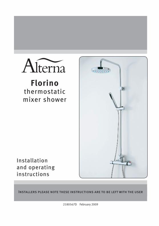
Installation and operating instructions
2180567D February 2009
Installers please note these instructions are to be left with the user
Florino thermostatic mixer shower
Bar mixer
CONTENTS Page
Introduction ......................................................................................... 1
Safety warnings ................................................................................... 1
Main components ................................................................................ 2
Site requirements ................................................................................ 3
Typical suitable installations ............................................................. 4 − 5
Instantaneous water heater appliance capabilities .............................. 6
Preparing the mixer valve .................................................................... 6
Siting of the shower ............................................................................. 6
Installation ....................................................................................... 7 − 8
Fitting the riser/fixed head rail ............................................................ 8
Leak testing ......................................................................................... 9
Commissioning .................................................................................... 9
Operating the shower ........................................................................ 10
Cleaning ............................................................................................. 11
Cleaning the filters.............................................................................. 11
Spare parts ......................................................................................... 12
Fault finding ................................................................................... 13 − 14
Guarantee, service policy, etc. ....................................................... rear cover
To check the product suitability for commercial and multiple installations, please contact specification advisory service before installation. Telephone: 0844 980 0748
Facsimile: 0844 980 0744
Bar mixer
�
INTRODUCTIONThis book contains all the necessary fitting and operating instructions for your Alterna Florino thermostatic mixer shower.
Please read these instructions carefully. Read through the whole of this book beFORe beginning your installation.
The shower installation MuST be carried out by a suitably competent person and in sequence of this instruction book.
Care taken during the installation will provide a long and trouble free life from your shower.
For the best performance within the specified running pressure range a minimum flow of eight litres per minute should be available to both inlets.
This mixer is designed to operate on higher pressure systems found in the uK up to a maximum of 5 bar running pressure. The valve MuST nOT be subjected to water temperatures above 80°C.
This mixer is suitable for fully modulating type combination boilers and multi-point hot water heaters. It is also suitable for thermal storage, unvented systems and pumped gravity systems.
Important: Before installing with a gas instantaneous water heater, make sure it is capable of delivering hot water at a minimum switch-on flow rate of 3 litres per minute. At flow rates between 3 and 8 litres per minute, the appliance must be capable of raising the water temperature to a minimum of 52°C. The water temperature at the inlet to the mixer must remain relatively constant when flow rate adjustments are made (refer to the water heater operating manual to confirm compatibility with this mixer shower).
Inlet connections are to 15 mm compression or ½” bSP female fittings (not supplied).
SAFETY WARNINGSa. Layout and sizing of pipework MuST be such
that when other services are used, pressures at the shower control inlets do not fall below the recommended minimum.
b. DO nOT choose a position where the shower could become frozen.
c. DO nOT connect this mixer shower to any form of tap or fitting not recommended by the manufacturer.
d. The showerhead MuST be regularly cleaned to remove scale and debris.
e. Conveniently situated service valves in each inlet supply MuST be fitted as an independent method of isolating the shower should maintenance or servicing be necessary.
f. If it is intended to operate the shower in areas of hard water (above 200 ppm temporary hardness), a scale inhibitor may have to be fitted. For advice on the scale inhibitor, please contact Customer Service.
g. DO nOT operate the shower outside the guidelines as laid out in ‘site requirements’.
Replacement parts can be ordered from Customer Service. See ‘spare parts’ for details and part numbers.
Bar mixer
�
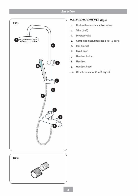
mAIN COmPONENTS (fig.1)
1. Florino thermostatic mixer valve
2. Trim (2 off)
3. Diverter valve
4. Combined riser/fixed head rail (2 parts)
5. Rail bracket
6. Fixed head
7. Handset holder
8. Handset
9. Handset hose
10. Offset connector (2 off) (fig.�)
Fig.�
Fig.�
�
�
3
4
9
8
7
5
4
6
�0
Bar mixer
3
Water temperature requirements
Maximum hot water temperature = 80°C
Recommended maximum = 65°C
Minimum hot water temperature = 52°C
Maximum cold water temperature = 20°C
bS 6700 recommends that the temperature of stored water should never exceed 65°C.
A stored water temperature of 60°C is considered high enough to meet all normal requirements and will minimise the effects of scale in hard water areas.
Temperature adjustment rangeThe mixed water temperature can be adjusted from cold through to a top limit which can be preset during installation with full anti-scald protection throughout the range (35°C to 40°C), providing the hot water temperature at the inlet remains 10°C above the outlet temperature.
Should there be a loss of flow to either incoming supply then water from the shower will stop or be reduced to a trickle until both supplies are restored.
SITE REqUIREmENTSThe installation MuST be in accordance with Water Regulations and bylaws.
Minimum running water pressure: 0.5 bar.
Maximum running water pressure: 5 bar.
Maximum static water pressure: 10 bar.
For the best performance within the specified running pressure range a minimum flow of eight litres per minute should be available to both inlets.
While the mixer shower is operational (open outlet), inlet pressures MuST nOT be capable of exceeding 7 bar. For effective operation of the internal seals, the maximum static pressure must not be exceeded.
note: On sites where the running pressure is above 5 bar, the use of a suitably sized pressure reducing valve fitted in the cold mains supply pipework can provide nominally equal pressures at the mixer shower.
For best performance both the hot and cold water supplies to the mixer should be fed at nominally equal pressures.
The pipework should be installed such that the flow is not significantly affected by other taps and appliances being operated elsewhere on the premises.
note: Where thermal store systems and instantaneous gas water heaters are used, if excessive draw-offs take place the boiler may not be able to maintain an adequate output temperature. This could result in the shower temperature becoming noticeably cooler.

Bar mixer
4
Fig.4 (diagrammatic view – not to scale)
Fig.3 (diagrammatic view – not to scale)TYPICAl SUITABlE INSTAllATIONS
a) Instantaneous gas-heated systems, e.g. combination boilers (fig.3)
The shower control MuST be installed with a multipoint gas water heater or combination boiler of a fully modulating design (i.e. to maintain relatively stable hot water temperatures).
A drop tight pressure reducing valve MuST be fitted if the supply pressures exceed 5 bar running.
An expansion vessel (shown in fig.3) MuST be fitted, and regularly maintained, to make sure the shower mixer is not damaged by excess pressures. This may already be installed within the boiler (check with manufacturer) and is in addition to the normally larger central heating expansion vessel.
The layout and sizing of pipework MuST be such that nominally equal inlet supply pressures are achieved and the effects of other draw-offs are minimised.
The hot supply temperature MuST remain a minimum of 10°C hotter than the required blend temperature for optimum performance.
b) Unvented mains pressure systems (fig.4)
The shower control can be installed with an unvented, stored hot water cylinder.
For systems with no cold water take off after the appliance reducing valve, it will be necessary to fit an additional drop tight pressure reducing valve when the mains pressure is over 5 bar. The drop tight pressure reducing valve must be set at the same value as the unvented package pressure reducing valve.
note: An additional expansion vessel (fig.4) may be required if a second pressure reducing valve is installed. This does not apply to packages with a cold take off after the pressure reducing valve to the cylinder.
The layout and sizing of pipework MuST be such that nominally equal inlet supply pressures are achieved and the effects of other draw-offs are minimised.
CH flow
Coldmainssupply
Hot water
CH return
Servicevalves
Mixer
Stoptap
Expansionvessel
Pressurereducing valve
Combinationboiler
Servicevalves
Balanced cold mains supply
Cold mains supply
Mixer
Expansionvessel
Pressurereducing
valves Stop tap
Unventedhot water
storage unit
Safety devicesnot shown
Bar mixer
5
Fig.5 (diagrammatic view – not to scale)
Fig.6 (diagrammatic view – not to scale)
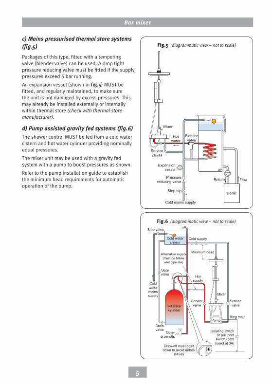
c) mains pressurised thermal store systems (fig.5)
Packages of this type, fitted with a tempering valve (blender valve) can be used. A drop tight pressure reducing valve must be fitted if the supply pressures exceed 5 bar running.
An expansion vessel (shown in fig.5) MuST be fitted, and regularly maintained, to make sure the unit is not damaged by excess pressures. This may already be installed externally or internally within thermal store (check with thermal store manufacturer).
d) Pump assisted gravity fed systems (fig.6)The shower control MuST be fed from a cold water cistern and hot water cylinder providing nominally equal pressures.
The mixer unit may be used with a gravity fed system with a pump to boost pressures as shown.
Refer to the pump installation guide to establish the minimum head requirements for automatic operation of the pump.
FlowReturn
Boiler
Blendervalve
Cold mains supply
Hotwater
Stop tap
Expansionvessel
Pressurereducing valve
Servicevalves
Mixer
Hot watercylinder
Mixer
Cold supply
Hotsupply
Alternative supply(must be belowvent pipe tee)
Coldwatermainssupply
Drainvalve
Gatevalve
Stop valve
Cold watercistern
Minimum head
Otherdraw-offs
Draw-off must pointdown to avoid airlock
issues
Ring main
Isolating switchor pull cord
switch (bothfused at 3A)
Servicevalve
Servicevalve
Pump
Bar mixer
6
Height ofshowerheadand shower
to suit user’srequirement.
Handset canbe positioned
either side of the rail.
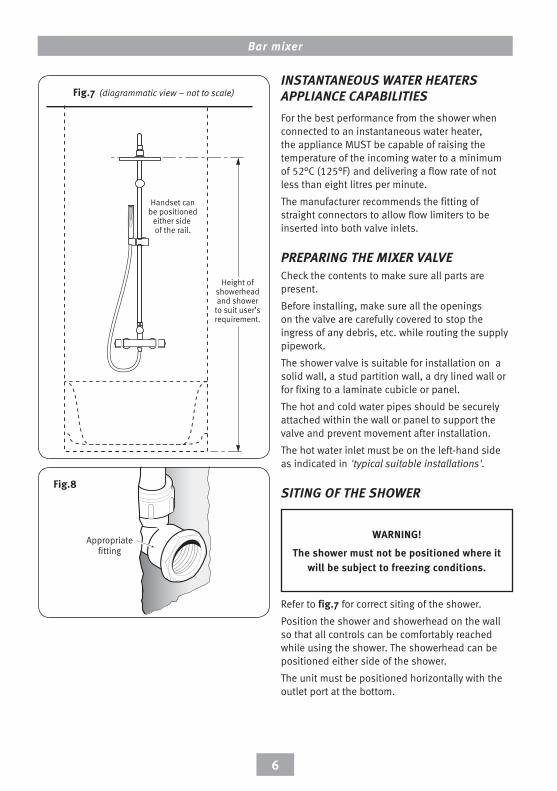
INSTANTANEOUS WATER HEATERS APPlIANCE CAPABIlITIESFor the best performance from the shower when connected to an instantaneous water heater, the appliance MuST be capable of raising the temperature of the incoming water to a minimum of 52°C (125°F) and delivering a flow rate of not less than eight litres per minute.
The manufacturer recommends the fitting of straight connectors to allow flow limiters to be inserted into both valve inlets.
PREPARING THE mIXER VAlVECheck the contents to make sure all parts are present.
before installing, make sure all the openings on the valve are carefully covered to stop the ingress of any debris, etc. while routing the supply pipework.
The shower valve is suitable for installation on a solid wall, a stud partition wall, a dry lined wall or for fixing to a laminate cubicle or panel.
The hot and cold water pipes should be securely attached within the wall or panel to support the valve and prevent movement after installation.
The hot water inlet must be on the left-hand side as indicated in 'typical suitable installations'.
SITING OF THE SHOWER
Refer to fig.7 for correct siting of the shower.
Position the shower and showerhead on the wall so that all controls can be comfortably reached while using the shower. The showerhead can be positioned either side of the shower.
The unit must be positioned horizontally with the outlet port at the bottom.
Fig.7 (diagrammatic view – not to scale)
WarnInG!
the shower must not be positioned where it will be subject to freezing conditions.
Appropriatefitting
Fig.8
Bar mixer
7
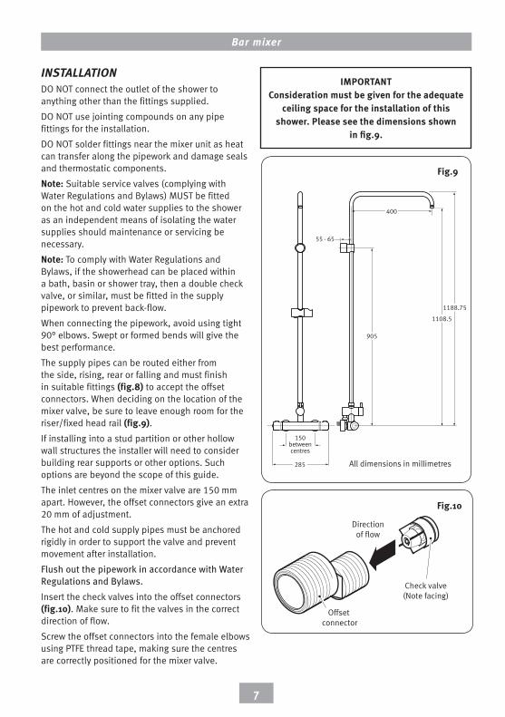
ImportantConsideration must be given for the adequate
ceiling space for the installation of this shower. please see the dimensions shown
in fig.9.
INSTAllATIONDO nOT connect the outlet of the shower to anything other than the fittings supplied.
DO nOT use jointing compounds on any pipe fittings for the installation.
DO nOT solder fittings near the mixer unit as heat can transfer along the pipework and damage seals and thermostatic components.
note: Suitable service valves (complying with Water Regulations and bylaws) MuST be fitted on the hot and cold water supplies to the shower as an independent means of isolating the water supplies should maintenance or servicing be necessary.
note: To comply with Water Regulations and bylaws, if the showerhead can be placed within a bath, basin or shower tray, then a double check valve, or similar, must be fitted in the supply pipework to prevent back-flow.
When connecting the pipework, avoid using tight 90° elbows. Swept or formed bends will give the best performance.
The supply pipes can be routed either from the side, rising, rear or falling and must finish in suitable fittings (fig.8) to accept the offset connectors. When deciding on the location of the mixer valve, be sure to leave enough room for the riser/fixed head rail (fig.9).If installing into a stud partition or other hollow wall structures the installer will need to consider building rear supports or other options. Such options are beyond the scope of this guide.
The inlet centres on the mixer valve are 150 mm apart. However, the offset connectors give an extra 20 mm of adjustment.
The hot and cold supply pipes must be anchored rigidly in order to support the valve and prevent movement after installation.
Flush out the pipework in accordance with Water Regulations and Bylaws.Insert the check valves into the offset connectors (fig.�0). Make sure to fit the valves in the correct direction of flow.
Screw the offset connectors into the female elbows using PTFe thread tape, making sure the centres are correctly positioned for the mixer valve.
150betweencentres
285
400
1188.75
1108.5
905
55 - 65
All dimensions in millimetres
Fig.9
Offset connector
Check valve(Note facing)
Directionof flow
Fig.�0
Bar mixer
8
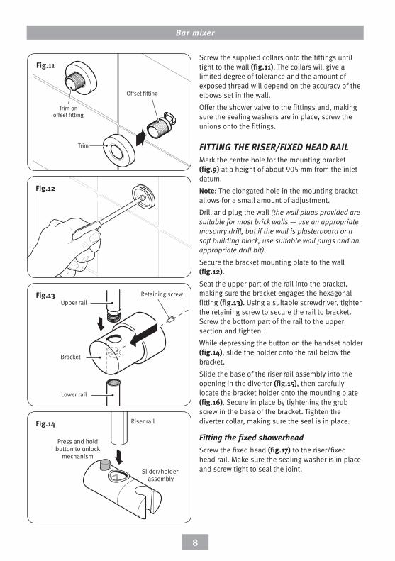
Screw the supplied collars onto the fittings until tight to the wall (fig.��). The collars will give a limited degree of tolerance and the amount of exposed thread will depend on the accuracy of the elbows set in the wall.
Offer the shower valve to the fittings and, making sure the sealing washers are in place, screw the unions onto the fittings.
FITTING THE RISER/FIXED HEAD RAIlMark the centre hole for the mounting bracket (fig.9) at a height of about 905 mm from the inlet datum.
note: The elongated hole in the mounting bracket allows for a small amount of adjustment.
Drill and plug the wall (the wall plugs provided are suitable for most brick walls — use an appropriate masonry drill, but if the wall is plasterboard or a soft building block, use suitable wall plugs and an appropriate drill bit).
Secure the bracket mounting plate to the wall (fig.��). Seat the upper part of the rail into the bracket, making sure the bracket engages the hexagonal fitting (fig.�3). using a suitable screwdriver, tighten the retaining screw to secure the rail to bracket. Screw the bottom part of the rail to the upper section and tighten.
While depressing the button on the handset holder (fig.�4), slide the holder onto the rail below the bracket.
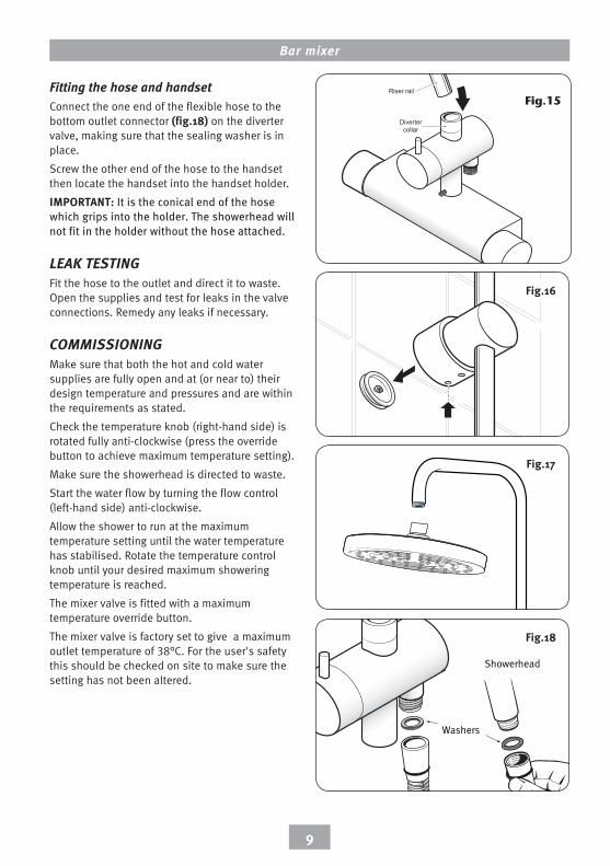
Slide the base of the riser rail assembly into the opening in the diverter (fig.�5), then carefully locate the bracket holder onto the mounting plate (fig.�6). Secure in place by tightening the grub screw in the base of the bracket. Tighten the diverter collar, making sure the seal is in place.
Fitting the fixed showerheadScrew the fixed head (fig.�7) to the riser/fixed head rail. Make sure the sealing washer is in place and screw tight to seal the joint.Slider/holder
assembly
Press and holdbutton to unlock
mechanism
Riser rail
Lower rail
Upper rail
Bracket
Retaining screwFig.�3
Fig.�4
Fig.��
Trim onoffset fitting
Trim
Offset fitting
Fig.��
Bar mixer
9
Fitting the hose and handsetConnect the one end of the flexible hose to the bottom outlet connector (fig.�8) on the diverter valve, making sure that the sealing washer is in place.
Screw the other end of the hose to the handset then locate the handset into the handset holder.
Important: It is the conical end of the hose which grips into the holder. The showerhead will not fit in the holder without the hose attached.
lEAk TESTINGFit the hose to the outlet and direct it to waste. Open the supplies and test for leaks in the valve connections. Remedy any leaks if necessary.
COmmISSIONINGMake sure that both the hot and cold water supplies are fully open and at (or near to) their design temperature and pressures and are within the requirements as stated.
Check the temperature knob (right-hand side) is rotated fully anti-clockwise (press the override button to achieve maximum temperature setting).
Make sure the showerhead is directed to waste.
Start the water flow by turning the flow control (left-hand side) anti-clockwise.
Allow the shower to run at the maximum temperature setting until the water temperature has stabilised. Rotate the temperature control knob until your desired maximum showering temperature is reached.
The mixer valve is fitted with a maximum temperature override button.
The mixer valve is factory set to give a maximum outlet temperature of 38°C. For the user's safety this should be checked on site to make sure the setting has not been altered.
Fig.�6
Washers
Showerhead
Fig.�7
Fig.�8
Divertercollar
Riser rail
Fig.15
Bar mixer
�0
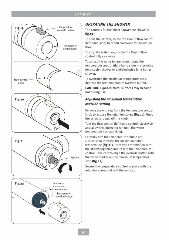
OPERATING THE SHOWERThe controls for the mixer shower are shown in fig.�9.
To start the shower, rotate the On/Off flow control (left-hand side) fully anti-clockwise for maximum flow.
To stop the water flow, rotate the On/Off flow control fully clockwise.
To adjust the water temperature, rotate the temperature control (right-hand side) — clockwise for a cooler shower or anti-clockwise for a hotter shower.
To overcome the maximum temperature stop, depress the red temperature override button.
CautIon: Exposed metal surfaces may become hot during use.
Adjusting the maximum temperature override setting
Remove the end cap from the temperature control knob to expose the retaining screw (fig.�0). undo the screw and pull off the knob.
Turn the flow control (left-hand control) clockwise and allow the shower to run until the water temperature has stabilised.
Carefully turn the temperature spindle anti-clockwise to increase the maximum outlet temperature (fig.��). Once you are satisfied with the showering temperature refit the temperature control. Take care to align the override button with the white marker on the maximum temperature stop (fig.��).Secure the temperature control in place with the retaining screw and refit the end cap.
Fig.�0
Fig.��
Temperature override button
Marker onmaximum
temperature stop
Fig.��
Temperatureoverride button
Flow controlknob
Temperaturecontrol knob
Temperatureoverride button
Flow controlknob
Temperaturecontrol knob
Fig.�9
Bar mixer
��
ClEANINGThe manufacturer recommends that all products are cleaned using warm, soapy water.
Do not use abrasive or aggressive chemical cleaning products as this may affect the product surface finish and invalidate your guarantee.
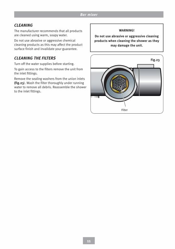
ClEANING THE FIlTERSTurn off the water supplies before starting.
To gain access to the filters remove the unit from the inlet fittings.
Remove the sealing washers from the union inlets (fig.�3). Wash the filter thoroughly under running water to remove all debris. Reassemble the shower to the inlet fittings.
Filter
Fig.�3
WarnInG!
Do not use abrasive or aggressive cleaning products when cleaning the shower as they
may damage the unit.
Bar mixer
��
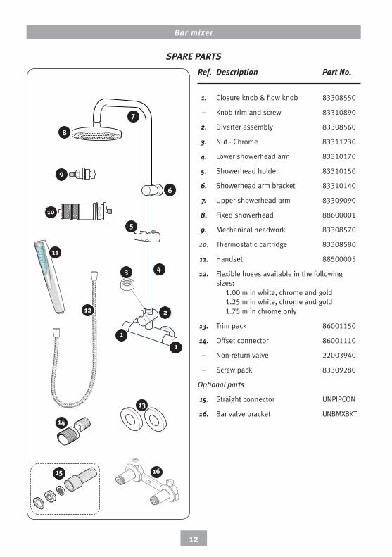
SPARE PARTS Ref. Description Part No.
1. Closure knob & flow knob 83308550
– Knob trim and screw 83310890
2. Diverter assembly 83308560
3. nut - Chrome 83311230
4. Lower showerhead arm 83310170
5. Showerhead holder 83310150
6. Showerhead arm bracket 83310140
7. upper showerhead arm 83309090
8. Fixed showerhead 88600001
9. Mechanical headwork 83308570
10. Thermostatic cartridge 83308580
11. Handset 88500005
12. Flexible hoses available in the following sizes: 1.00 m in white, chrome and gold 1.25 m in white, chrome and gold 1.75 m in chrome only
13. Trim pack 86001150
14. Offset connector 86001110
– non-return valve 22003940
– Screw pack 83309280
Optional parts
15. Straight connector unPIPCOn
16. bar valve bracket unbMXbKT
7
6
5
4
8
9
3
�
��
��
��
�3
�4
�5 �6
�0
Bar mixer
�3
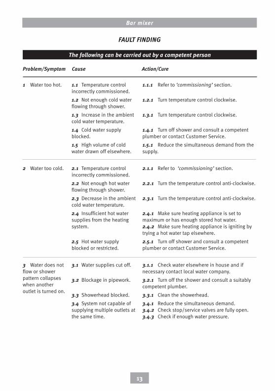
Problem/Symptom Cause Action/Cure
The following can be carried out by a competent person
1.1 Temperature control incorrectly commissioned.
1.2 not enough cold water flowing through shower.
1.3 Increase in the ambient cold water temperature.
1.4 Cold water supply blocked.
1.5 High volume of cold water drawn off elsewhere.
2.1 Temperature control incorrectly commissioned.
2.2 not enough hot water flowing through shower.
2.3 Decrease in the ambient cold water temperature.
2.4 Insufficient hot water supplies from the heating system.
2.5 Hot water supply blocked or restricted.
3.1 Water supplies cut off.
3.2 blockage in pipework.
3.3 Showerhead blocked.
3.4 System not capable of supplying multiple outlets at the same time.
1.1.1 Refer to ‘commissioning’ section.
1.2.1 Turn temperature control clockwise.
1.3.1 Turn temperature control clockwise.
1.4.1 Turn off shower and consult a competent plumber or contact Customer Service.
1.5.1 Reduce the simultaneous demand from the supply.
2.1.1 Refer to ‘commissioning’ section.
2.2.1 Turn the temperature control anti-clockwise.
2.3.1 Turn the temperature control anti-clockwise.
2.4.1 Make sure heating appliance is set to maximum or has enough stored hot water. 2.4.2 Make sure heating appliance is igniting by trying a hot water tap elsewhere.
2.5.1 Turn off shower and consult a competent plumber or contact Customer Service.
3.1.1 Check water elsewhere in house and if necessary contact local water company.
3.2.1 Turn off the shower and consult a suitably competent plumber.
3.3.1 Clean the showerhead.
3.4.1 Reduce the simultaneous demand. 3.4.2 Check stop/service valves are fully open. 3.4.3 Check if enough water pressure.
1 Water too hot.
2 Water too cold.
3 Water does not flow or shower pattern collapses when another outlet is turned on.
FAUlT FINDING

Bar mixer
�4
Problem/Symptom Cause Action/Cure
The following is recommended for a professional qualified installer only
4.1 Running pressure in excess of maximum recommended.
5.1 Running pressure in excess of maximum recommended.
6.1 Flow control washer worn.
4.1.1 Fit a pressure reducing valve.
5.1.1 Fit a pressure reducing valve.
6.1.1 Renew flow control washer.
4 Water too cold.
5 Shower controls noisy while in use.
6 Shower will not shut off.
FAUlT FINDING

Bar mixer
�5
Bar mixer
�6
Bar mixer
�7
Distributed in the UK for Jewson LimitedAldwych House81 AldwychLondonWC2B 4HQ.Registered in England & Wales No. 348047
The Manufacturers reserve the right to change product specification without prior notice. E&OA.
Standard GuaranteeThis product against all mechanical defects arising from faulty workmanship or materials for a period of five years for domestic use only, from the date of purchase, provided that it has been installed by a competent person in full accordance with the fitting instructions.Any part found to be defective during this guarantee period we undertake to repair or replace at our option without charge so long as it has been properly maintained and operated in accordance with the operating instructions, and has not been subject to misuse or damage.This product must not be taken apart, modified or repaired except by an authorised. This guarantee applies only to products installed within the United Kingdom and does not apply to products used commercially. This guarantee does not affect your statutory rights.
What is not covered:1 Breakdown due to: a) use other than domestic
use by you or your resident family; b) wilful act or neglect; c) any malfunction resulting from the incorrect use or quality of water or incorrect setting of controls; d) faulty installation.
2 Repair costs for damage caused by foreign objects or substances.
3 Total loss of the product due to non-availability of parts.
4 Compensation for loss of use of the product or consequential loss of any kind.
5 Call out charges where no fault has been found with the appliance.
6 The cost of repair or replacement of showerheads, hoses, riser rails and/or wall brackets or any other accessories installed at the same time.
7 The cost of routine maintenance, adjustments, overhaul modifications or loss or damage arising therefrom, including the cost of repairing damage, breakdown, malfunction caused by corrosion, furring, pipe scaling, limescale, system debris or frost.
Customer Service: % 0844 980 0749
trade Installer Hotline: % 0844 980 0748
Fax: 0844 980 0744
Service PolicyIn the event of a product fault or complaint occurring, the following procedure should be followed:1 Telephone Customer Service on 0844 980 0749 having available,
your details including post code, the model number and power rating of the product, together with the date of purchase.
2 Based on information given over the telephone, a Customer Service Advisor will attempt to diagnose the fault and confirm whether a site visit from a qualified service engineer is required.
3 All products attended to by a service engineer must be installed in full accordance with the installation guide applicable to the product. (Every product pack contains an installation guide, however, they can also be bought via our Customer Service Spares Department).
4 Our engineer will require local parking and if a permit is required this must be available to the engineer on arrival at the call.
5 It is essential that you or an appointed representative (who must be over 18 years of age) is present for the duration of the service engineer's visit. If the product is in guarantee you must produce proof of purchase.
6 Where a call under the terms of guarantee has been booked and the failure is not product related (i.e. scaling and furring, incorrect water pressure, pressure relief device operation or electrical/plumbing installation fault) a charge will be made. A charge will also be issued if nobody is at home when the service engineer calls or adequate parking/permit is not available.
7 If the product is no longer covered by the guarantee an up front fixed fee will be charged before the site visit.
8 Should proof of purchase not be available on an “in-guarantee” call, or should the service engineer find that the product is no longer under guarantee, the engineer will charge the same fixed price and the customer will be expected to pay the engineer before he leaves. If payment is not made on the day an administration charge will be added to the fixed charge.
9 If a debt is outstanding from a previous visit, or from any other purchase, we reserve the right to withhold service until the debt has been settled.
10 We take the health, safety and wellbeing of our employees very seriously and expects customers to treat all staff members with respect. Should any employee feel threatened or receive abuse, either verbally or physically, we reserve the right to withhold service and will support our employee with a legal prosecution.
replacement Parts PolicyAvailability: It is the policy of the manufacturer to maintain parts availability for the duration of production and a period of five years thereafter, in accordance with industry standards.Payment should be made by credit/debit card (excluding American Express or Diners Card).Payment can also be made by pre-payment of a pro forma invoice by cheque or money order.