floor system vibration control · suggests that a floor system’s vibration characteristics are...
TRANSCRIPT

Floor System Vibration Control
E.M. Hines, Ph.D., P.E., Res. Asst. Professor, Tufts University, Dept. Civ. & Env. Eng.; Associate, LeMessurier Consultants
M. Ravindra, P.E., President, LeMessurier ConsultantsC.D. Blanchet, P.E., Associate, LeMessurier Consultants
M. Sanayei, Ph.D., Professor, Tufts University, Dept. Civ. & Env. Eng.M.D. Dodge, Graduate Res. Asst., Tufts University, Dept. Civ. & Env. Eng.
R. Viesca, Undergraduate Res. Asst., Tufts University, Dept. Civ. & Env. Eng.
Abstract
Experience in the design of steel and concrete floor systems to control vibrations suggests that a floor system’s vibration characteristics are often fundamental to its acceptable performance. In such cases, serviceability drives the design instead of strength. This is particularly true for laboratory floors that support sensitive equipment and floor girders that fall within certain spans. This paper discusses the initiation of a long-term collaborative research program between Tufts University and LeMessurier Consultants to investigate the vibration characteristics of a variety of floor systems. Examples include new concrete-steel composite floor systems, concrete floor systems, and irregular floor systems, and floor systems that have required remediation. The paper introduces well-known basic floor vibration equations and parameters, and discusses the possibility for developing further the concepts inherent in these equations for the purposes of improved conceptual design of floor systems to control vibrations.
Introduction
Recent structural designs for high-tech laboratories by LeMessurier Consultants have prompted the research team to begin developing conceptual design criteria for laboratory floor systems subject to stringent vibration tolerances. Fundamental choices regarding structural materials and the structural system layout made during conceptual design can significantly influence the final design and resulting construction process. Many of these new laboratories are being built specifically to house highly sensitive equipment necessary for research in fields such as nanotechnology and biotechnology that are coincident with major NSF directives. Increased construction of such facilities across the United States has created the need for improved structural design and assessment approaches that ensure: (1) reliable resistance to vibration demands, (2) flexibility in building layouts, and (3) economy in design and construction. The issue of floor vibration mitigation through structural design has created a significant relationship between the well-established discipline of structural engineering and the emerging fields
of nanotechnology and biotechnology. Reliable floor vibration design to satisfy stringent tolerances is essential to state of the art research in these rapidly developing fields.
Studies on human perceptibility of floor vibrations date back more than 70 years (Reiher and Meister 1931), and critical experimental and analytical work on floor vibrations due to human activity was conducted throughout the past 30 years (Murray 1975, Murray 1991, Bachmann 1992). However, widely accepted design criteria for floor vibrations have arisen chiefly during the past decade in the form of an official AISC design guide (Murray, Allen and Ungar 1997). The current design guideline constitutes a large improvement over the previous state of the practice, because it focuses more on the mechanisms that drive floor vibration. But this improvement is often not enough to satisfy the rigorous requirements of high-tech facilities and laboratories. The accuracy and generality of vibration design guidelines can, be further enhanced in several areas, the most important of which include irregular floor systems and concrete floor systems.
Research Program
The goal of this research is to develop experimental data and an approach to enhance the analysis and design for floor vibration. This improvement is greatly needed for design of today’s high-tech laboratory facilities, which depend on increasingly tight tolerances for vibration control. While existing design criteria for vibration are effective and conservative for regular floor systems, irregular systems are difficult to assess accurately. Furthermore, far fewer precedents exist for vibration analysis and control ofall- concrete floor systems than for steel-concrete composite systems. Typically this is not a concern, because, concrete designs result in stiff, massive systems that are naturally suited to control vibrations. However, the effectiveness of concrete designs remains difficult to assess numerically when making initial choices about the type of floor system to use in a design. This lack of knowledge leaves designers, owners and vibration consultants to make critical decisions regarding structural materials and system layout based primarily on anecdotal experience. Finally, while damping is less important for laboratory floor systems concerned with peak velocity response, it is a key parameter for mitigating floor vibrations in all floor systems designed to ensure human comfort. Damping remains, however, the most difficult vibration parameter to predict and assess analytically. Since decisions on the nature of a floor system are made during the earliest stages of the design process, it is critical to develop reliable conceptual design approaches that address the choice of material, improved understanding of structural boundary conditions for irregular floor plans, and more precise determination of damping.
In the current process, most floor systems are designed to satisfy strength and stiffness requirements and then checked analytically for vibration. Using this process, floor vibration control is typically not evaluated until after the earliest and most critical stages of design when most of the key structural decisions are made. Further development of

conceptual design criteria to evaluate floor vibrations will allow structural engineers to communicate more effectively with architects and owners about vibration serviceability issues during conceptual design. This development depends on systematic and comprehensive experimental assessments of actual floor systems, rigorous comparison between predictions, experimental results and improved analytical models, and effective communication of results through both innovative and well- established channels.
Current analytical models that are practical to be used in a design office for the assessment of floor vibrations are based on a large number of full-scale vibration tests on existing buildings. This data is largely unavailable, however, at the level of detail required for its effective application for further, more specific evaluation. Furthermore, use and interpretation of data from large-scale structural tests is dependent upon the test setup and instrumentation scheme. For both these reasons, and due to the case-by-case approach required for the accurate assessment of irregular floor systems, concrete floor systems and damping, researchers wishing to improve design approaches for controlling floor vibrations must develop their own database of floor vibration tests.
Background in Laboratory Design
LeMessurier Consultants has designed numerous scientific laboratories, many of which require the satisfaction of stringent floor system vibration tolerances in order to house sensitive equipment. Six recent laboratories are featured in Table 1.
Table 1. Laboratories designed by LeMessurier Consultants according stringent vibration limits.
Owner Building Material Criteria OpeningCornell Nanotechnology Laboratory RC 1000 µ"/s Fall 2003Harvard Institute of Medicine SS 2000 µ"/s Summer 2005MIT Brain and Cognitive Science Center SS 2000 µ"/s Spring 2005Duke Science Center RC 2000 µ"/s Fall 2006U. Chicago Interdivisional Research Center SS 0750 µ"/s Summer 2005U. Mass Worcester Research Institute SS 2000 µ"/s Fall 2000
Table 1 lists the owner, laboratory name, structural system, design criteria and completion dates for each of these laboratories. In the “material” column, “RC” (reinforced concrete) refers to an all-concrete floor system with concrete slab, beams and girders. The material “SS” (structural steel) refers to a composite steel-concrete floor system with concrete slab on steel deck, steel beams, and steel girders. The peak velocity design criteria for these laboratories were evaluated according to Equation (1).
While most of these laboratories were designed to satisfy the relatively standard peak velocity criterion of 2000 µ"/s (50.8 µm/s), laboratories at Cornell (Figure 1) and the University of Chicago were designed, at the request of the owner and chief scientists, for more stringent criteria. Furthermore, the Cornell, University of Chicago and Harvard

Figure 1. Duffield Hall Nanofabrication Facility at Cornell.(Courtesy of Zimmer Gunsul Frasca Partnership)
laboratories were designed to have clean rooms at the foundation level that satisfied a criterion of 250 µ"/s (6.35 µm/s).
The design of these clean rooms has raised the question of how designers can appropriately assess foundations for vibration behavior. The values of 1000 µ"/s (25.4 µm/s) for Cornell, and 750 µ"/s (19 µm/s) for the University of Chicago represent criteria for framed systems. In order to meet these criteria, it was necessary to decrease the column spacing from 32' to 27' (9.75 m to 8.23 m) on center for the Cornell laboratories, and to increase the concrete composite slab thickness to 5 ½" (140 mm) above the 3" (76 mm) metal deck in the University of Chicago Laboratories. The selection of vibration criteria for a given facility usually involves a compromise between flexibility in planning and cost. The tradeoff is to design the overall facility for a less stringent level of vibrations, but then identify special locations for less vibration. Particularly sensitive equipment is placed in selected locations such as basement areas, near columns, away for corridors. Additional vibration mitigation is sometimes achieved by placing equipment on vibration isolation pads.
The following guidelines were set for the University of Chicago Interdivisional Research Center at the very early stages of design. The design of this type of facility requires collaboration between the vibration consultant, structural engineer, mechanical engineer, architect and the owner. In the case of the University of Chicago, this collaboration was carefully coordinated from the beginning of the project and maintained through completion of the building.
1. Identify and evaluate environmental vibration.2. Assign vibration criteria for equipment.3. Educate the owner and select vibration criteria for the facility.4. Layout the equipment and design the structure accordingly.5. Conduct meetings between the owner, structural engineers, mechanical
engineers, and vibration consultants to allocate premium costs.6. Develop mechanical equipment isolation guidelines and specifications for the
mechanical contractor.
Evaluation of environmental vibration requires assessments of a wide range of vibration sources. These include:

1. Site conditions such as highways, subways, rail lines, and loading docks.2. Building equipment such as pumps, pipes and ducts.3. Human traffic, where vibration demand increases with increased walking speeds.4. Movement of carts, forklifts, and dollies.5. Mechanical rooms that house chillers, boilers and other equipment.
Mounting the equipment on vibration isolation systems can mitigate vibrations due to mechanical equipment, piping and ducts. This requires sufficient space and firm structural supports. Vibrations due to human traffic are typically mitigated directly in the design of the structural system. Close attention must be paid to walking speeds that are generally assessed as relatively slow in laboratories, moderate in other areas and short corridors, and fast in long corridors. Full vibration mitigation under fast walking speeds is nearly impossible to achieve. It is therefore important to understand and plan the relationships between corridors and laboratories such that they are structurally isolated from one another. In cases where such isolation cannot be achieved, the effects of fast walking on vibrations in an adjacent bay remain to be established.
All of the laboratories listed in Table 1 were designed according to the AISC Design Guidelines in order to satisfy vibration criteria. For both the Cornell and Duke laboratories, the AISC Design Guidelines for structural steel were simply applied to reinforced concrete according to standard assumptions of material mass and stiffness. In such cases, stiffnesses of the concrete beams were assessed according to uncracked section properties based on the assumption that the extremely small amplitudes in question would not result in significant reduction in beam stiffness. This assumption was drawn from experience in steel-concrete composite floors where it has been shown that the full transformed composite moment of inertia may be used for assessing member stiffness. Since concrete members often crack under dead loads, there is some question as to whether the application of this logic to all-concrete floor systems is appropriate. If concrete beams are already cracked, is it correct to model their stiffness to resist vibrations using uncracked section properties?
Standard Floor Vibration Testing Protocol
Experimental methods consist of a basic procedure that will be applied to a wide range of floor systems identified and organized by LeMessurier Consultants in the New England area. This procedure consists of three basic steps:
1. Estimate the excited natural frequencies under simulated vibration demands.2. Assess floor system natural frequencies in detail under resonance testing.3. Estimate damping according to the decay of oscillations after each resonance
test.
Primary experimental data includes frequency, peak velocity and acceleration amplitudes, and damping for each floor system in question. Tufts University Researchersgather this data according to a systematic experimental protocol that allows for the complexities of irregular floor systems, extremely stiff floor systems, effects of floor

Figure 2. APS dynamics shaker in vertical orientation with 4 reaction masses.
system vibrations on adjacent bays, and spatial variation of vibrations within a given bay.
A range of excitations are used in the experimental evaluation of floor vibration characteristics. These excitations include heel drop tests, heavier weight drop tests, and resonance testing. Measured time history responses to these excitations will be transferred to the frequency domain using the Fast Fourier Transform (FFT). FFT results are then used to determine the excited natural frequencies and the level of participation in the total response. Damping ratios can quickly be approximated using the Sharpness of Resonance method (Thomson and Dahleh, 1998).
Once the excited frequencies have been estimated, floor systems are subjected to sine dwell and resonance testing in order to establish their natural frequency and damping characteristics accurately. Independent velocity and acceleration measurements arerecorded for all excitations. These independent measurements are cross-correlated to check the reliability of their relationship according to system natural frequency. The rate of decay of oscillations measured by logarithmic decrement (Thomson and Dahleh, 1998) allows a more accurate evaluation of the damping ratios. Since various nonlinearties such as micro-cracks in concrete floors can alter the damping ratio, it is important to perform these tests at the magnitude allowed by the serviceability limits based of the usage of these floors.
General characteristics of structural damping are complex and are related to hysteretic damping and presence of various types of nonlinearties including presence of micro-cracks in reinforced concrete (Ewins, 1986). For ease of analysis of low damped systems and ease of development of mathematical models that can mimic the behavior of a low-damped physical system, equivalent viscous damping ratios per mode of vibration will be used. These models account for similar levels of energy dissipation in lightly damped systems and create a good mathematical match with nondestructive test data.
Resonance testing is completed with a computer-controlled shaker-controller-amplifier for floor vibration testing that will be interfaced with the new DAQ system to provide the type of excitation required for floor vibration testing (Figure 2).
Experimental Data vs. Existing AISC Criteria
Existing floor vibration design criteria differentiate between two types of excitation: excitation from walking, and excitation from rhythmic activity (Murray, Allen and Ungar 1997).

Acceptance criteria for both types of excitation were calibrated experimentally and depend heavily on parameters such as damping and overall system frequency. For non-repetitive or irregularly shaped floor spans these dynamic characteristics can be very difficult to evaluate. The design of laboratories and other buildings supporting sensitive equipment, the basic velocity criterion is
vn
p
U
V
f≤∆
(1)
where ∆p = displacement of the floor due to a concentrated load, fn = natural frequency of the floor system, V = peak velocity limit (commonly 2000 µ"/s (50.8 µm/s) for laboratories, but outlined in detail in (Ungar, Sturtz and Amick, 1990; and Ungar, 1992)), and Uv = footfall impulse parameter that varies from 1,500 lb.Hz2 (6675 NHz2) for slow walking speeds to 25,000 lb.Hz2 (111,250 NHz2) for fast walking speeds. Note that this criterion focuses on peak velocity and does not depend on damping. For floor systems designed to meet human comfort criteria, the acceptance criterion for acceleration excitation from walking is given as,
g
a
W
eP
g
a nfp 0
35.00 ≤=
−
β (2)
where P0 = constant force equal to 65 lb (289 N) for floors and 92 lb (409 N) for foot bridges, ap/g = estimated peak acceleration (in units of g), a0/g = design criteria acceleration limit, fn = natural frequency of the floor system, β = damping ratio, and W = effective weight of the floor. The acceptance natural frequency criterion for rhythmic excitation (from dancing or aerobic exercise for example) is given as,
t
pin w
w
ga
kff
α/
10
+≥ (3)
where f = forcing frequency, k = constant (1.3 for dancing, 1.7 for a lively concert or sports event, 2.0 for aerobics), αi = a dynamic coefficient specified by the design criteria, wp = effective weight of participants per unit area, wt = effective total weight per unit area (participants + floor).
Both acceptance criteria, given in Equations 2 and 3, depend on values that were calibrated experimentally. The acceptance criterion in Equation 2 for excitation due to walking depends not only on the system damping, β, but also on a constant forcing function, P0, an experimentally calibrated exponential dependence on system frequency, and experimentally determined acceptance criteria. The acceptance criterion in Equation 2 for rhythmic excitation depends on the constant, k, and the dynamic coefficient, ai, and experimentally determined acceptance criteria. Furthermore, both Equations 2 and 3 depend on the natural frequency of the system. For regular floor systems, the natural frequency can be evaluated simply with satisfactory accuracy. For irregular floor

systems, however, the natural frequency depends heavily on the boundary conditions of the system, and the effective weight, W, becomes more difficult to assess.
Equations 1, 2 and 3 represent relationships that are critical to evaluating whether the vibration characteristics of a given floor system are acceptable for normal use. These equations depend heavily on values that have been calibrated experimentally for regular floor systems based on a wide spread of experimental damping values. For instance, experimental evaluation of the pedestrian bridge shown in Figure 3 recently revealed a damping value of β = 4% as opposed to the 1% value typically assumed for such structures. It is typically thought that glass railings offer substantial damping to such
systems. According to Equation 2, this increase from 1% to 4% impliesthat the vibration accelerations are reduced by a factor of 4. Experimental validation of these equations and characterization of the range in which they are valid constitutes a necessary foundation for advancing the state of the art in floor system vibration mitigation.
Figure 3. Boston Convention Center main lobby pedestrian bridge.
Irregular Floor Systems Frequency Characteristics
It is often necessary to evaluate irregular floor systems for vibration. Irregular conditions include special boundary conditions that are highly fixed or free to deform as cantilevers, openings in the floor slab with its resulting framing, and other irregular geometry introduced by the architecture, site and facility requirements. In assessing floor system boundary conditions, it is essential to develop a clear understanding of the relative effects of fixity on floor vibration characteristics. For instance, Ungar has recommended to avoid relying on the fixity provided by steel girder moment connections because the fixity does not appear to affect system behavior at the extremely low levels of amplitude under consideration in the design of floor systems to support sensitive equipment (Murray, Allen and Ungar, 1997). Vibration analysis of irregular floor systems also leads to questions on how vibrations in one bay of framing may affect the response of another bay of framing. Knowledge of this coupling between bays is

extremely important for determining placement of sensitive equipment and the designation of walking zones inside of a laboratory. These questions can be addressed using finite element analysis or other analytical methods. The methods require modeling of boundary conditions regardless of whether the whole system or only a subsection is analyzed. The investigators have worked with several scientists who have noticed vibration problems in one part of their laboratory and satisfactory performance in other areas of the same laboratory. Such behavior is clearly related to the placement equipment in proximity to columns or to midspans. Therefore, understanding the boundary conditions is essential to effective analysis, particularly for irregularities in the floor systems.
In many cases, LeMessurier Consultants has developed detailed elastic finite element models to assess the natural frequencies of irregular floor systems. Typically, once the frequencies have been assessed, this information applied in the vibration assessment equations and further vibration assessment is conducted in a manner similar to a more regular floor system. This practice has resulted in two fundamental questions: 1) what amount of irregularity requires the creation of a detailed finite element model? and 2) once the model has been created, would it not make more sense to apply footfall and other excitation loads directly to the model as dynamic time history functions? The following example from a balcony of the Life Sciences Building at the University of Pennsylvania (Figure 4), which is currently under construction, demonstrates the issues associated with assessing an irregular floor system. The parameters in Equation 1 that can vary are fn = floor system natural frequency, W = floor system effective weight, and β = floor system damping. Each of these parameters may vary widely. Hence, differentcombinations of these parameters for the same system will significantly affect the results. Of these three parameters, only the natural frequency can be evaluated by a relatively straightforward analysis via finite element models. The effective weight maybe accounted for by applying heel-drop loading to a finite element model as a dynamic time-history. Damping must be evaluated experimentally. As part of a typical design process, all of these parameters would be determined according to the AISC Design Guide.
In the following example, the cantilever displacement was determined to be ∆c = 0.0808 in. (2.05 mm) and the girder displacement was assessed as ∆g = 0.0246 in. (0.624 mm). Then the system frequency is
90.10in.0246.0in.0808.0
in./s38618.0
2
=+
=nf Hz
Assuming that the balcony behaves as an interior footbridge gives P0 = 92 lbs (409 N), and assuming very little damping gives β = 0.01. Finally, assuming an effective weight of W = 30.83 kips (137.2 kN), the peak acceleration can be calculated according to Equation (2) as

Frequency = 9.411 Hz
W18
x35
W18x76
W10x68
W10x77
W10x88
W18x60
RIGID LINKS
4 NODEPLATE STRETCHING &
BENDING ELEMENTS
Figure 4. FEM of the balcony designed for the Life Sciences Building at the University of Pennsylvania.
)(015.0)(00658.0)kips83.30)(01.0(
)kips092.0( )90.10)(35.0(
gge
g
a p ≤==−
which implies that the floor system accelerations are well below the acceptable limits. During the design process, members of the research team created a finite element model of this structural system in order to check the approximate natural frequency (Figure 4).
Applying the more accurate natural frequency of 9.411 Hz, Equation (2) produces a peak acceleration of 0.0119(g), which is 81% higher than the Design Guide estimate and 63% closer to the allowable limit. A designer evaluating the vibration characteristics of this floor system based on the Design Guide alone might elect to reduce the stiffness of the system based on the result of 0.00658(g) < 0.015(g). Based on the finite element model, however, such a decision might result in vibration problems. This example demonstrates that small variations in the system natural frequency (14%) can cause large variations in peak acceleration (81%).
While the other parameters, W and β, do not have such a drastic effect on Equation (2), they are more prone to wide variation. The example above assessed Waccording to the dead weight of the entire floor system (46 psf (slab) + 15.66 psf (steel))(500 ft2)/1000 = 30.83 kips (137.2 kN).
This decision is based on experience and engineering judgment. An alternative evaluation of the weight based only on the cantilevered portion of the floor system would result in a value of 8.17 kips (36.4 kN), 3.77 times less than the appropriate weight. Furthermore, Murray has reported values for the damping ratio, β, that range from 0% to 14% of critical damping (Murray, 1981). Both W and β are related linearly to the peak acceleration value. In certain design cases, for irregular floor systems, where the numbers suggest that the floor system has peak accelerations just above or below the allowable limit, parameters with such potential for variation give little insight into appropriate design solutions. For this reason, while Equation (2) itself may be appropriate, the parameters in this equation must be more clearly and accurately understood. This will only be possible through the detailed evaluation of multiple irregular floor systems.
Concrete Floor Systems
Analysis and experimental study of the concrete floor system supporting the structures laboratory at Tufts University has shown that not only is the frequency of such a floor system difficult to determine even with sophisticated finite element analysis, but also that the damping in such floor systems is typically very high.
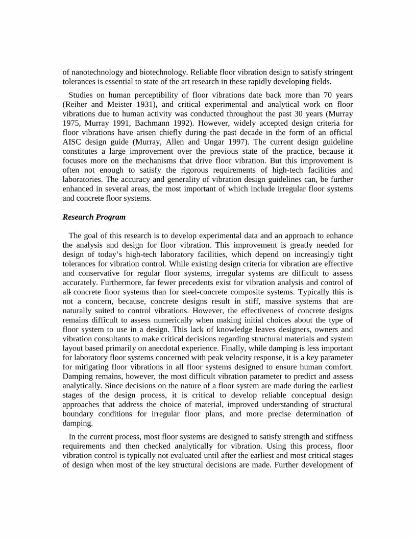
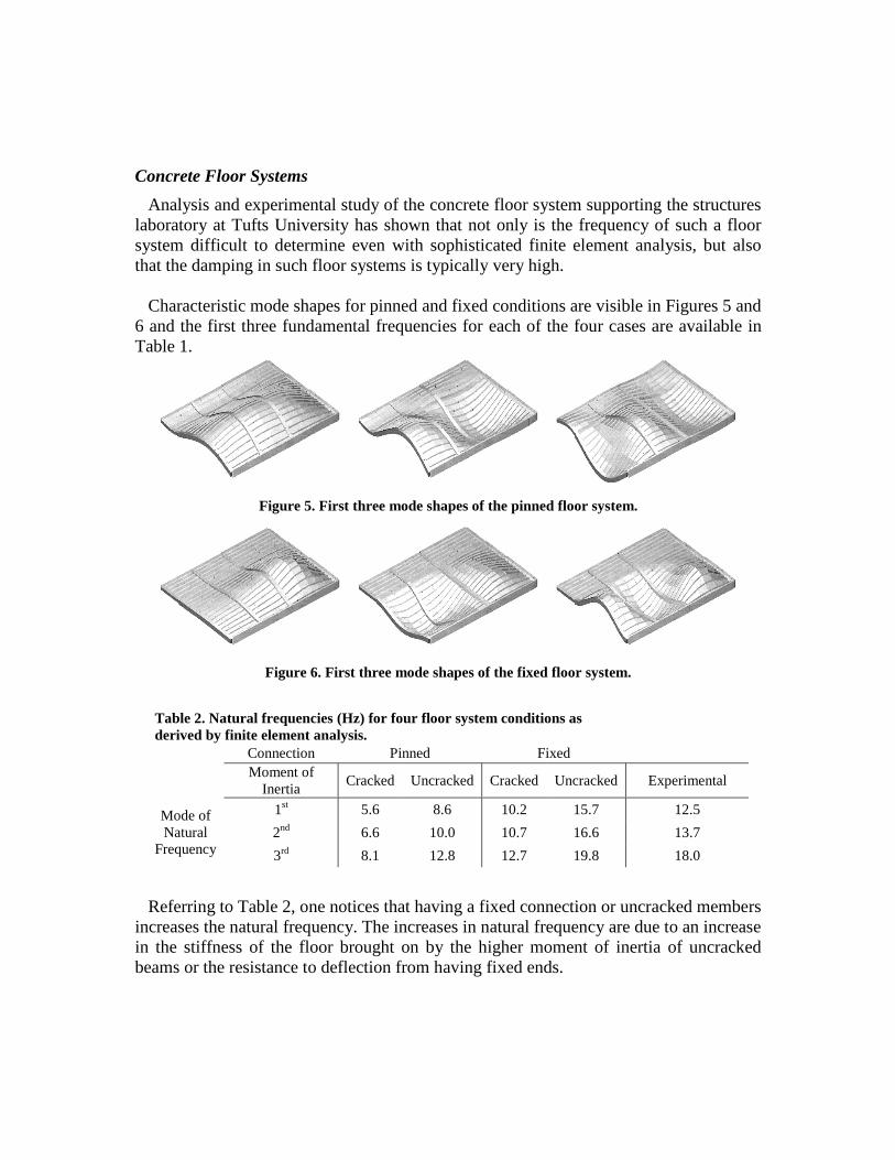
Characteristic mode shapes for pinned and fixed conditions are visible in Figures 5 and 6 and the first three fundamental frequencies for each of the four cases are available in Table 1.
Figure 5. First three mode shapes of the pinned floor system.
Figure 6. First three mode shapes of the fixed floor system.
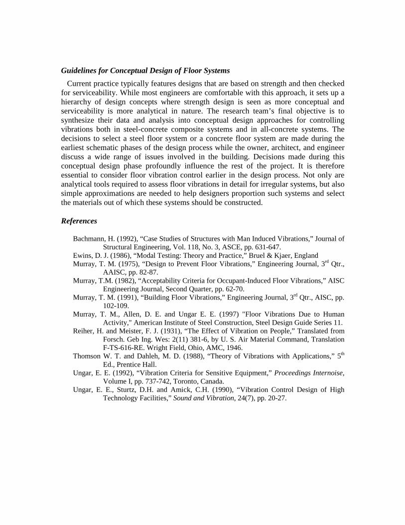
Table 2. Natural frequencies (Hz) for four floor system conditions as derived by finite element analysis.
Connection Pinned FixedMoment of
InertiaCracked Uncracked Cracked Uncracked Experimental
1st 5.6 8.6 10.2 15.7 12.5
2nd 6.6 10.0 10.7 16.6 13.7Mode of Natural
Frequency 3rd 8.1 12.8 12.7 19.8 18.0
Referring to Table 2, one notices that having a fixed connection or uncracked members increases the natural frequency. The increases in natural frequency are due to an increase in the stiffness of the floor brought on by the higher moment of inertia of uncracked beams or the resistance to deflection from having fixed ends.
Guidelines for Conceptual Design of Floor Systems
Current practice typically features designs that are based on strength and then checked for serviceability. While most engineers are comfortable with this approach, it sets up a hierarchy of design concepts where strength design is seen as more conceptual and serviceability is more analytical in nature. The research team’s final objective is to synthesize their data and analysis into conceptual design approaches for controlling vibrations both in steel-concrete composite systems and in all-concrete systems. The decisions to select a steel floor system or a concrete floor system are made during the earliest schematic phases of the design process while the owner, architect, and engineer discuss a wide range of issues involved in the building. Decisions made during this conceptual design phase profoundly influence the rest of the project. It is therefore essential to consider floor vibration control earlier in the design process. Not only are analytical tools required to assess floor vibrations in detail for irregular systems, but also simple approximations are needed to help designers proportion such systems and select the materials out of which these systems should be constructed.
References
Bachmann, H. (1992), “Case Studies of Structures with Man Induced Vibrations,” Journal of Structural Engineering, Vol. 118, No. 3, ASCE, pp. 631-647.
Ewins, D. J. (1986), “Modal Testing: Theory and Practice,” Bruel & Kjaer, EnglandMurray, T. M. (1975), “Design to Prevent Floor Vibrations,” Engineering Journal, 3rd Qtr.,
AAISC, pp. 82-87.Murray, T.M. (1982), “Acceptability Criteria for Occupant-Induced Floor Vibrations,” AISC
Engineering Journal, Second Quarter, pp. 62-70.Murray, T. M. (1991), “Building Floor Vibrations,” Engineering Journal, 3rd Qtr., AISC, pp.
102-109.Murray, T. M., Allen, D. E. and Ungar E. E. (1997) "Floor Vibrations Due to Human
Activity," American Institute of Steel Construction, Steel Design Guide Series 11.Reiher, H. and Meister, F. J. (1931), “The Effect of Vibration on People,” Translated from
Forsch. Geb Ing. Wes: 2(11) 381-6, by U. S. Air Material Command, Translation F-TS-616-RE. Wright Field, Ohio, AMC, 1946.
Thomson W. T. and Dahleh, M. D. (1988), “Theory of Vibrations with Applications,” 5th
Ed., Prentice Hall.Ungar, E. E. (1992), “Vibration Criteria for Sensitive Equipment,” Proceedings Internoise,
Volume I, pp. 737-742, Toronto, Canada.Ungar, E. E., Sturtz, D.H. and Amick, C.H. (1990), “Vibration Control Design of High
Technology Facilities,” Sound and Vibration, 24(7), pp. 20-27.