control of variable frequency vibration in large span … · regarding footfall thinduced floor...
TRANSCRIPT
Proceedings of Acoustics 2012 - Fremantle 21-23 November 2012, Fremantle, Australia
Australian Acoustical Society 1
Control of variable frequency vibration in large span composite construction floor in a high rise building
Tim Marks (1), Dr Len Koss (2) and Michael Plumb (3)
(1) Associate Director, Marshall Day Acoustics, Melbourne, Australia
(2)Associate, Marshall Day Acoustics, Melbourne, Australia
(3)Executive Engineer, Embelton, Melbourne, Australia
ABSTRACT
A new 31 storey commercial building was the subject of complaints regarding excessive floor vibration. There were some concerns
regarding footfall induced floor vibration, but the majority of complaints came from the 19th floor, above the 18th floor plant room
where a number of large, slow speed, vibration isolated, centrifugal fans were operated by variable speed drives (VSDs).
It was a simple matter to identify that the fans, when operating at 360rpm, generated significant energy that excited the floor directly
above the plant room, whose first natural frequency was also identified at being around 6Hz.
Controlling and reducing the vibration was less straightforward. Due to their size, the fans could not be replaced. The greatest
vibration occurred at the floor mid span and tuned mass vibration dampers (TMD’s) were specified to reduce the floor response at
6Hz. Following the TMD design and installation, occupant complaints continued and it was established that the variable speed
operation and the extreme occupant sensitivity at 6Hz resulted in annoyance even when the AS2670 threshold for offices was met by
a factor of 10dB or more. The problem was eventually solved with a unique design of variable frequency tuned dampers
conceptualized and specified by Marshall Day Acoustics (MDA) and designed and supplied by G.P. Embelton & Co. A total of 4
such dampers were successfully installed at strategic locations under the L-19 floor with very significant vibration reduction results.
INTRODUCTION
The Southern Cross Building (SX1) Melbourne is a conventional
commercial office tower with a central core, and steel reinforced
concrete floor slabs. The composite floor consists of 610UB101
primary beams or girders, with 9m spans between columns; and
15m long secondary beams or joists (from core to curtain wall)
also 610UB101 members, with a separation of 3m.
The floor slab is 120mm thick 32MPa concrete poured on
Condek formwork with a 40mm pre camber.
The Victorian Government Purchasing Guidelines (VGPG) used
by the client for the SX1 project provided no vibration criteria.
Accordingly three commonly used standards were considered for
establishing a criterion for assessment purposes.
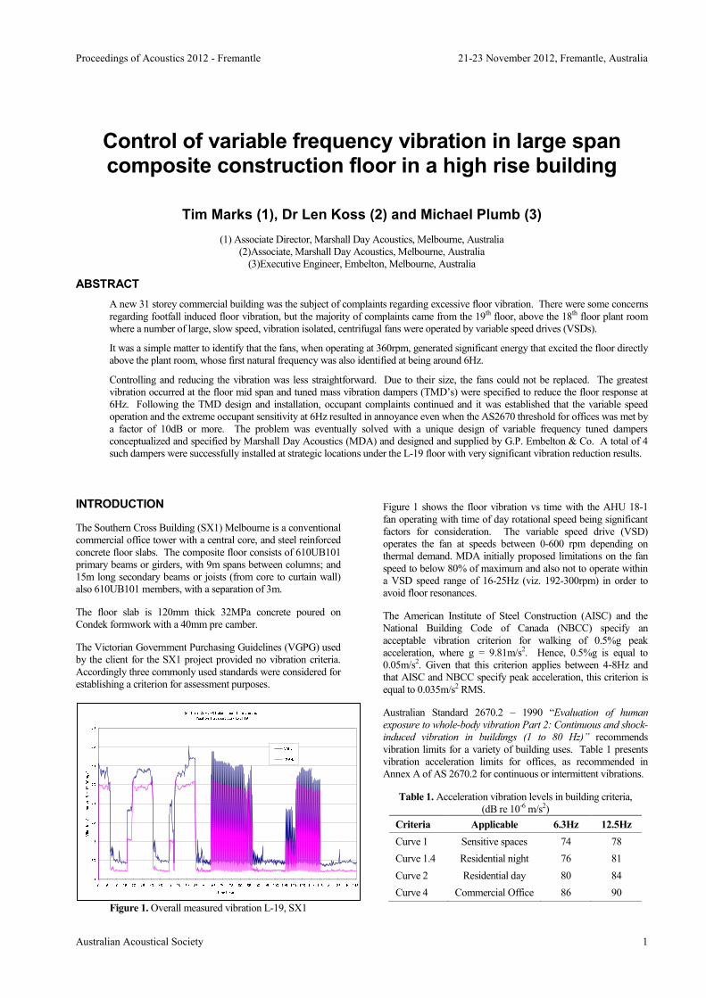
Figure 1. Overall measured vibration L-19, SX1
Figure 1 shows the floor vibration vs time with the AHU 18-1
fan operating with time of day rotational speed being significant
factors for consideration. The variable speed drive (VSD)
operates the fan at speeds between 0-600 rpm depending on
thermal demand. MDA initially proposed limitations on the fan
speed to below 80% of maximum and also not to operate within
a VSD speed range of 16-25Hz (viz. 192-300rpm) in order to
avoid floor resonances.
The American Institute of Steel Construction (AISC) and the
National Building Code of Canada (NBCC) specify an
acceptable vibration criterion for walking of 0.5%g peak
acceleration, where g = 9.81m/s2. Hence, 0.5%g is equal to
0.05m/s2. Given that this criterion applies between 4-8Hz and
that AISC and NBCC specify peak acceleration, this criterion is
equal to 0.035m/s2 RMS.
Australian Standard 2670.2 – 1990 “Evaluation of human
exposure to whole-body vibration Part 2: Continuous and shock-
induced vibration in buildings (1 to 80 Hz)” recommends
vibration limits for a variety of building uses. Table 1 presents
vibration acceleration limits for offices, as recommended in
Annex A of AS 2670.2 for continuous or intermittent vibrations.
Table 1. Acceleration vibration levels in building criteria,
(dB re 10-6 m/s2)
Criteria Applicable 6.3Hz 12.5Hz
Curve 1 Sensitive spaces 74 78
Curve 1.4 Residential night 76 81
Curve 2 Residential day 80 84
Curve 4 Commercial Office 86 90

Proceedings of Acoustics 2012 - Fremantle 21-23 November 2012, Fremantle, Australia
Australian Acoustical Society 2
INVESTIGATION OF VIBRATION SOURCES
The dominant source of the observed vibration at L-19 of SX1 is
AHU 18-1; when this unit was switched off, little vibration was
perceptible even when standing directly above AHU 18-3. At
the other end of the building on the same floor, the vibration
from AHU 18-2 and 18-4 was also perceptible, but of lower
magnitude and less likely to lead to such extreme complaints.
One test determined that a (horizontal) system resonance
occurred at 230rpm. This is equivalent to 3.8Hz which indicated
that the spring isolators under the fans were not correctly loaded.
The project specification nominated 50mm deflection coil steel
springs with a natural frequency of 2Hz. The 3.8Hz resonance
may be a lateral (viz horizontal) mode, although since coil
springs are normally less stiff horizontally than vertically, we
suspected this was a measure of vertical resonance, and was too
high.
Several attempts were made to dynamically balance the fans and
adjust the drive belt drive tension; however there was no
resulting appreciable change in vibration.
As the source of vibration was directly related to AHU’s 18-1
and 8-3, the investigations were directed at identifying potential
vibration transmission paths to the building structure and in
particular to the L-19 floor slab above.
Following one inspection the following fundamental actions
were recommended:
Frequency banding to restrict fan operation outside the
critical range of interest.
All AHU 18-1 supply air ductwork should be suspended by
combined spring and neoprene rubber hangers with a
deflection of at least 50mm. Any identified bridging of
isolators by incorrectly aligned hanger rods or hangers were
corrected.
The roof of the AHU enclosure had to be installed so that
there was no direct connection between the AHU roof panels
and the L-19 floor slab above. If connected by rigid hangers
including wire or chain, then vibration isolators were
required
The walls of the AHU enclosure could not run full height
from the floor of L-18 to the underside of L-19 above. Any
structural elements that breached between the two that were
attached to the AHU enclosure had to be decoupled using
flexible isolated connections
Where the supply air duct passed through the AHU
enclosure penetration a clearance of 50mm was required on
all sides to prevent transmission of duct borne vibration to
the AHU walls.
Figure 2. AHU 18 -1 SA fans being lifted into position during
construction
Other surveys also confirmed that the axial type return air fans
(RAF), TEF and GEF fans were not major contributors to the
floor vibration even though all were mounted from the L-19 slab.
UPWARDS OR DOWNWARDS PROPAGATION
Vibration level measurements were also performed on L-17 to
provide a comparison with the L-19 levels. A comparison of the
measured vibration on AHU 18-3, at 75% duty, showed the
vibration on L-17 was significantly less than on L-19. The
difference in measured levels was possibly due to the following:
Differences in structure between L-17 and L-19
A unique airborne or structure borne transmission path via
the L-18 plantroom ceiling directly into the L-19 slab, but
not into the L-17 slab
Figure 3. Relative Floor Vibration Levels 17 and 19 (with AHU
18-3 operating)
REVIEW OF OPTIONS
The rectification works and the frequency banding (fan speed
range limiting) on AHU’s 18-1 and 18-2 were expected to reduce
the vibration levels on L-19. However, at rotational speeds
outside the banding range (16-25Hz) and under certain load
conditions, e.g. 100% duty, the vibration was still unacceptable
to the occupants.
Figure 4 shows the progressive reduction in vibration since the
rectification work was commenced. These figures show

Proceedings of Acoustics 2012 - Fremantle 21-23 November 2012, Fremantle, Australia
Australian Acoustical Society 3
reductions of about 15dB at 6.3Hz and reductions of about 11dB
at 12.5Hz. The result was an improvement in vibration to a level
below that required for residential premises during the daytime
period (AS2670 Curve 2).
Figure 4. Vibration changes after initial rectifications
Figure 4 shows that, over a period of time, the vibration
progressively decreased; however the 6Hz vibration level was
below 80dB although this still represented perceptible vibration.
In discussing what was an acceptable vibration level, MDA
decided that levels of between 60-75dB were acceptable, levels
between 75-80dB were marginal, and levels above 80dB were in
excess of what is probably fit for purpose. This target is more
stringent than the AS2670.2 Curve 4 criteria for commercial
buildings and is comparable to that acceptable for residential
buildings (Curve 2).
A second peak at 13Hz was consistent with the fan second
harmonic, which excited one of the many higher floor modes.
Shown in Figure 5 are plots of L-18 floor acceleration levels
versus frequency for the four operating fans on L-17.
AIRBAG ISOLATION
The preferred option for vibration mitigation was to increase the
floor slab stiffness so the vibration isolators could achieve higher
performance, as a result of the increased structural rigidity. This
option was evaluated extensively by Bonacci Consulting
Engineers. Increasing the plant room floor stiffness, and hence
raising the floor natural frequency substantially, was not practical
or feasible as an increase of at least 25% was required. One
alternative solution was to replace the fans with smaller, high-
speed units that would operate at speeds in excess of 500rpm.
Again this solution was not practical or achievable.
STRUCTURAL DAMPING OPTIONS
As neither of the above options was viable then the installation of
vibration dampers was considered. There are two alternative
vibration damper systems, namely: passive vibration dampers
(Tuned Mass Dampers (TMD)), and active vibration control
dampers which use electronic control systems to counteract the
vibratory forces.
A 10dB reduction in vibration was considered to be a suitable
design target for the performance of the selected vibration
damping system.
INITIAL MITIGATION MEASURES
After much work MDA formed the view that the vibration on L-
19 was being transmitted from the plantroom by one of two
phenomena; airborne excitation or structure-borne flanking.
Surveys had indicated that vibration was not transmitting up the
core or structural columns, or via the ring beam and window
mullions into the L-19 floor.
Figure 5. Acceleration levels for the four operating fans across
the building
Table 2. Measured vibration acceleration levels at 6.3Hz third
octave
Operating Condition Vibration
Level 19
AHU 18-3 alone at 75% duty 86-87 dB
AHU 18-1 alone at 75% duty 79-80 dB
Both 18-3 and 18-1 at 75% 86-87 dB
Both 18-2 and 18-4 at 75% 56-57 dB
Background 55dB
HYBRID TUNED MASS DAMPER (TMD) SOLUTION
With vibration levels at 6Hz, considered excessive; even after
many modifications, a tuned mass damper was trialled to
determine the reduction possible at 6Hz. The design of the TMD
is based upon theory given by Rao and the prototype is shown in
Figure 6 with no damping and Figure 7 with damping. The
estimated effective floor mass was 20,000 kg and using a 430 kg
TMD mass this gave a mass ratio of 2.15 %.

Proceedings of Acoustics 2012 - Fremantle 21-23 November 2012, Fremantle, Australia
Australian Acoustical Society 4
Figure 6. Prototype TMD without viscous damping
Figure 7. Prototype TMD with viscous dampers
This simple prototype TMD, was tuned to a resonant frequency
of 6 Hz. Tests were then undertaken with the TMD on L-19 with
the AHU 18-1 fan operating at 360 rpm. Floor acceleration
spectra were obtained for the case of no TMD and the two TMD
configurations (un-damped and damped). These spectra are
shown in Figure 8 which shows large vibration reductions
obtained at 5.9 Hz; the acceleration level results are shown in
Table 3.
Table 3. Vibration reduction at 5.9Hz obtained by the prototype
TMD, dB re 10-6 m/s2
Scenario Spectrum
Level, dB
Vibration
Reduction,
dB
No TMD 70.5 -
TMD and no damping 49 21.5
TMD with damping 60 10.5
Theoretical 600 kg TMD*
design
n/a 16
*With optional damping
A higher level of vibration reduction can be achieved using the
un-damped TMD, but to prevent a possible secondary resonance
being excited damping is required. A 3 % mass ratio TMD with
optimal damping was selected with an expected vibration
reduction of 16dB.
Figure 8. L-19 floor vibration spectra showing original spectrum
(solid line with dot) un-damped spectrum (broken line) and the
damped TMD (solid line).
Four TMD devices were installed on L-19 to control vibration
generated by each AHU in the L-18 plant room. It was decided
to use one TMD design for all four positions. The specifications
of the TMD are as follows:
Spring stiffness of 1,320kN/m
Mass of 700 kg ± 200kg
Damper variable range from 6200-7700Ns/m
Design floor frequency of 6.1Hz for excitation
frequency at 75% of fan duty
TMD variable frequency range (dampers) between
4.9Hz and 9.1Hz.
The variation of the mass lever arm allows for tuning as it is
easier to vary mass than to vary stiffness.
The resulting floor vibration above AHU 18-1 with the damped
conventional TMD attached to the structure is shown in Figure 9.
Figure 9. Measured vibration compliance. Vibration with no
TMD is black line and floor vibration with TMD is red line.
The results showed a significant reduction and the achievement
of Curve 1 to AS2670 (74dB at 6Hz).
3 4 5 6 7 8 9 1040
45
50
55
60
65
70
75
Frequency (Hz)
Accele
ration (
dB
re 1
e-6
m/s
2)
SX1 Level 19 Floor vibration spectra comparisons 30/07/08 (tests 000, 008 and 010)
430 kg TMD with oil
430 kg TMD no oil
Original spectrum and No TMD
Southern Cross 1 Level 19 Predicted Vibration Reduction Using a TMD: AHU 18.1 at 75% Duty & AHU
18.3 Off
40
50
60
70
80
90
100
0.4 0.6 1.0 1.6 2.5 4.0 6.3 10.0 16.0 25.0 40.0 63.1 100.0 160.0 250.0 400.0
Frequency (Hz)
Accele
rati
on
(d
B r
e 1
0^
-6 m
/s^
2)
Position 1 No TMD
Position 1 with TMD
AS 2670.2 Laboratory Curve 1
AS 2670.2 Residentail Curve 2
AS 2670.2 Office Curve 4

Proceedings of Acoustics 2012 - Fremantle 21-23 November 2012, Fremantle, Australia
Australian Acoustical Society 5
VARIABLE EXCITATION DUE TO CHANGE OF AHU SPEED
The AHU fan speed is based upon load demand which is not
constant and thus the excitation frequency, continuously changes.
The measured acceleration above AHU 18-1 for varying fan
speed is shown in Figure 10. The results in Figure 10’s light
indicate a non compliance at a fan operating frequency of 6.7 Hz.
Thus, the fixed frequency TMD was not capable of reducing
floor acceleration at all fan operating speeds.
A variable frequency TMD was designed to address this
problem. The TMD mass sits on an arm at the free end; the other
end is held by a pivot joint. At the free end the TMD spring and
damper are located. The entire unit is rigidly attached to the L-19
floor to provide efficient force transfer with minimal
displacement. On-site tuning was required to match the exact
floor frequency to the TMD resonant frequency. The TMD was
designed to achieve a 20 year design life with regular
maintenance and servicing. Variable tuning is obtained by
moving the TMD mass back and forth along the arm using a
worm drive. Details of the variable frequency TMD are given in
Figures 11 and 12, and schematic is shown in Figure 13.
Figure 10. Measured acceleration at 6.3 Hz on L-19 with
varying fan operational frequency
Figure 11. Side view of variable frequency TMD, during factory
testing.
Figure 12. End view of variable frequency TMD showing
dashpot and spring during commissioning.
Figure 13. Details of the auto-tracking TMD attached to the
L-19 floor.
The position of the mass is varied by a worm drive and motor
controlled by the VSD driven rotational speed of the AHU.
The installation and commissioning was conducted jointly by
MDA, Embelton and the builder, Brookfield Multiplex.
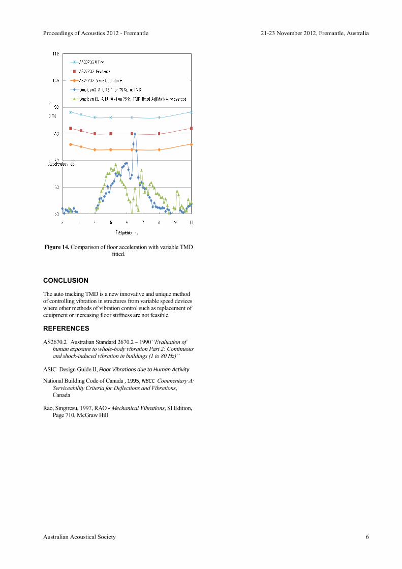
Measurements of vibration above AHU 18-1 with and without
the auto-tracking TMD are given in Figure 14. The floor
vibration with the auto – tracking TMD is about 20 dB less in the
6 Hz to 6.8 Hz frequency range. This figure demonstrates the
usefulness of the auto- tracking TMD in achieving significant
reductions in floor vibration by the use of the variable speed
AHU’s.
Proceedings of Acoustics 2012 - Fremantle 21-23 November 2012, Fremantle, Australia
Australian Acoustical Society 6
Figure 14. Comparison of floor acceleration with variable TMD
fitted.
CONCLUSION
The auto tracking TMD is a new innovative and unique method
of controlling vibration in structures from variable speed devices
where other methods of vibration control such as replacement of
equipment or increasing floor stiffness are not feasible.
REFERENCES
AS2670.2 Australian Standard 2670.2 – 1990 “Evaluation of
human exposure to whole-body vibration Part 2: Continuous
and shock-induced vibration in buildings (1 to 80 Hz)”
ASIC Design Guide II, Floor Vibrations due to Human Activity
National Building Code of Canada , 1995, NBCC Commentary A:
Serviceability Criteria for Deflections and Vibrations,
Canada
Rao, Singiresu, 1997, RAO - Mechanical Vibrations, SI Edition,
Page 710, McGraw Hill